EP1674405B1 - Non-metallic twist tie - Google Patents
Non-metallic twist tie Download PDFInfo
- Publication number
- EP1674405B1 EP1674405B1 EP03754110A EP03754110A EP1674405B1 EP 1674405 B1 EP1674405 B1 EP 1674405B1 EP 03754110 A EP03754110 A EP 03754110A EP 03754110 A EP03754110 A EP 03754110A EP 1674405 B1 EP1674405 B1 EP 1674405B1
- Authority
- EP
- European Patent Office
- Prior art keywords
- tie
- property
- twist tie
- binding
- shape
- Prior art date
- Legal status (The legal status is an assumption and is not a legal conclusion. Google has not performed a legal analysis and makes no representation as to the accuracy of the status listed.)
- Expired - Lifetime
Links
Images


Classifications
-
- B—PERFORMING OPERATIONS; TRANSPORTING
- B65—CONVEYING; PACKING; STORING; HANDLING THIN OR FILAMENTARY MATERIAL
- B65D—CONTAINERS FOR STORAGE OR TRANSPORT OF ARTICLES OR MATERIALS, e.g. BAGS, BARRELS, BOTTLES, BOXES, CANS, CARTONS, CRATES, DRUMS, JARS, TANKS, HOPPERS, FORWARDING CONTAINERS; ACCESSORIES, CLOSURES, OR FITTINGS THEREFOR; PACKAGING ELEMENTS; PACKAGES
- B65D63/00—Flexible elongated elements, e.g. straps, for bundling or supporting articles
- B65D63/10—Non-metallic straps, tapes, or bands; Filamentary elements, e.g. strings, threads or wires; Joints between ends thereof
-
- B—PERFORMING OPERATIONS; TRANSPORTING
- B65—CONVEYING; PACKING; STORING; HANDLING THIN OR FILAMENTARY MATERIAL
- B65D—CONTAINERS FOR STORAGE OR TRANSPORT OF ARTICLES OR MATERIALS, e.g. BAGS, BARRELS, BOTTLES, BOXES, CANS, CARTONS, CRATES, DRUMS, JARS, TANKS, HOPPERS, FORWARDING CONTAINERS; ACCESSORIES, CLOSURES, OR FITTINGS THEREFOR; PACKAGING ELEMENTS; PACKAGES
- B65D63/00—Flexible elongated elements, e.g. straps, for bundling or supporting articles
- B65D63/10—Non-metallic straps, tapes, or bands; Filamentary elements, e.g. strings, threads or wires; Joints between ends thereof
- B65D63/12—Joints produced by deformation or tying of ends of elements
-
- Y—GENERAL TAGGING OF NEW TECHNOLOGICAL DEVELOPMENTS; GENERAL TAGGING OF CROSS-SECTIONAL TECHNOLOGIES SPANNING OVER SEVERAL SECTIONS OF THE IPC; TECHNICAL SUBJECTS COVERED BY FORMER USPC CROSS-REFERENCE ART COLLECTIONS [XRACs] AND DIGESTS
- Y10—TECHNICAL SUBJECTS COVERED BY FORMER USPC
- Y10T—TECHNICAL SUBJECTS COVERED BY FORMER US CLASSIFICATION
- Y10T24/00—Buckles, buttons, clasps, etc.
- Y10T24/15—Bag fasteners
-
- Y—GENERAL TAGGING OF NEW TECHNOLOGICAL DEVELOPMENTS; GENERAL TAGGING OF CROSS-SECTIONAL TECHNOLOGIES SPANNING OVER SEVERAL SECTIONS OF THE IPC; TECHNICAL SUBJECTS COVERED BY FORMER USPC CROSS-REFERENCE ART COLLECTIONS [XRACs] AND DIGESTS
- Y10—TECHNICAL SUBJECTS COVERED BY FORMER USPC
- Y10T—TECHNICAL SUBJECTS COVERED BY FORMER US CLASSIFICATION
- Y10T24/00—Buckles, buttons, clasps, etc.
- Y10T24/15—Bag fasteners
- Y10T24/153—Plastic band bag tie
-
- Y—GENERAL TAGGING OF NEW TECHNOLOGICAL DEVELOPMENTS; GENERAL TAGGING OF CROSS-SECTIONAL TECHNOLOGIES SPANNING OVER SEVERAL SECTIONS OF THE IPC; TECHNICAL SUBJECTS COVERED BY FORMER USPC CROSS-REFERENCE ART COLLECTIONS [XRACs] AND DIGESTS
- Y10—TECHNICAL SUBJECTS COVERED BY FORMER USPC
- Y10T—TECHNICAL SUBJECTS COVERED BY FORMER US CLASSIFICATION
- Y10T24/00—Buckles, buttons, clasps, etc.
- Y10T24/15—Bag fasteners
- Y10T24/157—Twist-to-close bag tie
Definitions
- the present invention relates to a nonmetallic twist tie having no core line in the core part or having no wire for a core line in the core part and being able to form into a good wound shape in a bundle.
- the tie is used for binding a material to be bound using a binding machine mostly in food companies where bread, confectionery, etc. are manufactured or sold, in agricultural garden companies where cut flower, etc. are produced or sold, in electric and electronic instrument companies where electric and electronic products with wiring devices are manufactured or sold, etc.
- twist tie which is hardly corroded, is able to prevent injury of fingertip, does not cause electric leakage and is able to be used for a metal detector where a synthetic resin line such as polyester is used as a core line and a synthetic resin material such as polyethylene, polypropylene or polyester is used as a coating material.
- a coreless twist tie using no core line in the core part which is composed of a crystalline thermoplastic synthetic resin such as polyethylene resin, polypropylene resin, polyamide resin, polybutylene terephthalate resin and polyethylene terephthalate resin and glass beads having a particle size of not larger than 60 ⁇ and prepared by elongation where the elongation rate is 2.5-fold or more whereby it is easily twisted and is able to retain its twisted binding state.
- a crystalline thermoplastic synthetic resin such as polyethylene resin, polypropylene resin, polyamide resin, polybutylene terephthalate resin and polyethylene terephthalate resin and glass beads having a particle size of not larger than 60 ⁇ and prepared by elongation where the elongation rate is 2.5-fold or more whereby it is easily twisted and is able to retain its twisted binding state.
- U. S. Patent No. 5,154,964 there is a disclosure for a ribbon-shaped wireless twist tie having no core line in the core part which is easily twisted and easily loosened.
- the tie is prepared by elongation, to an extent of 2.5-fold or more, of a polymer resin having a degree of crystallization of 10 to 60% at the crystallization temperature of about 100 to 250°C.
- twist ties in which the core part has no core line or wire is not used for the core line of the core part and the material used for the coating material is constituted from a non-halogenous material such as olefin resin, improvement in their properties is significant and, in the shape being cut in a short size, they fully achieve their function and have been able to be used without problem.
- ability of the core part for forming a fixed shape is essentially weaker than wire and, moreover, the coating material has higher hardness than soft PVC as compared with the conventional twist ties where wire is used as a core line and PVC is used as a coating material. Therefore, they are not convenient for a shape of being wound in a bundle like in the case of winding on a reel.
- the present invention has been achieved for solving the problems in the prior art as such and its object is to provide a nonmetallic twist tie in which the function inherent to the twist tie is of course available and the twist tie is easily made into a shape of being wound in a bundle whereby its drawing-out from the wound shape is able to be carried out smoothly.
- an object of the present invention is to provide a nonmetallic twist tie in a shape of a ribbon in which both core part and wing part are constituted from a non-halogenous material and necessary function inherent to the twist tie such as torsion property and binding property are fully achieved wherein, during forming and retaining its state of being wound in a bundle, there is little occurrence of slipping down of the tie into gap of a reel, torsion and curl of the tie itself, twining and tangling of ties, loosening or disjoining in a wound state and, during the operation of forming and retaining its state of being wound in a bundle and mechanical binding of a material to be bound, there is materlialized a smooth drawing-out from the wound state.
- a ribbon-shaped nonmetallic twist tie having a core part and a wing part constituted from a non-halogenous material, the core part and wing part each extend the length of the tie, the tie having a total width of 1.5 to 20.0 mm, a maximum thickness of the wing part of 0.02 to 0.20 mm and a maximum thickness of the core part of 0.04 to 0.30-fold of the total width, characterized in that it is obtained by lamination molding with the use of a plastic core material which is highly elongated to an extent of 10-fold or more, or by extrusion molding of a compounded substance to which a filler is added followed by subjecting to an elongation of 2.5-fold or more, and in that it has a property of forming a fixed shape of 90% or more and a property of retaining a fixed shape of 70 to 95%.
- the non-metallic twist tie of the present invention has a binding property where the torsion strength is 5.0 to 15 N, a rigidity where the tensile elasticity is 5,000 to 30,000 Mpa, a drawing-out property where a degree of curving to the drawing-out direction is 10° or less and a winding property where curl radius to the winding direction retains the range of 50 to 200 mm.
- the nonmetallic twist tie 1 of the present invention takes a form of nonmetallic twist tie 1a in an extrusion molding type as shown in Fig. 2 or takes a form of nonmetallic twist tie 1b in a lamination type as shown in Fig. 3 .
- the former tie 1a is able to be prepared, for example, by extrusion of a compounded composition where a non-halogenous resin is a main component into a shape having core part 3 and wing part 4 to conduct an extrusion integral molding while the latter tie 1b is able to be prepared, for example, by making a non-halogenous plastic core line 5 intrinsic in core part 3 and by layering, on upside and downside thereof, a coating material 6 of a plastic film constituted from a non-halogenous resin or a coating material 6 such as paper or nonwoven fabric where said film is laminated in the inner surface thereof to conduct a lamination molding.
- Those nonmetallic twist ties 1a/1b are supplied in a state as shown in Fig. 1 where they are wound in a long size in a bundle form on a winding jig (reel).
- the nonmetallic twist tie 1 of the present invention is applied, for example, to a binding machine 11 as shown in Fig. 4 whereby the use in a wound state 2 of as long as, for example, about 500 m to 5,000 m is made possible although there is no particular limitation for the length.
- a binding machine 11 such as a torsion strength (expressed by a binding force measured by a method as shown in Fig. 6 ) in a torsion state as shown, for example, in Fig.
- a nonmetallic twist tie 1 When a nonmetallic twist tie 1 is wound in a bundle form such a wound around a reel or the like, the phenomena such as slipping down of the bound tie 1 into gap of a reel 2a, torsion and curl of the tie itself, twining and tangling of ties 1 or loosening or disjoining of tie 1 from the reel 2a are apt to happen upon winding, transportation and use.
- curl of the twist tie 1 results in a curl in the winding direction of the reel 2a causing a binding mistake.
- disjoining and loosening of the twist tie 1 in a wound shape 2 due to poor property of forming a fixed shape and poor property of retaining a fixed shape of the twist tie 1 are the causes for difficulty in twist in the binding using a binding machine or for breakage of the wing.
- the present inventors have intensively carried out studies for solving those problems and, as a result, they have found that, when curving degree ⁇ upon drawing-out of the twist tie 1 and curl radius r to a winding direction are controlled within a predetermined range, a good state of drawing out causing no induction of binding mistake is able to be achieved.
- a curving degree a to left and to right against the drawing-out direction is kept within 10°.
- the reason is that, when the curving degree is more than 10°, it often happens that the tie is not well held by a binding machine 11 resulting in a binding mistake.
- a curl radius r to the winding direction is to be within a range of 50 to 200 mm. The reasons is that there are many cases that, when it is more than 200 mm, an upward curvature occurs and a continuous binding by a binding machine 11 is difficult while, when it is less than 50 mm, a downward curvature occurs resulting in troubles for a continuous binding by a binding machine 11.
- the present inventors have further investigated the shape of a bound tie 1 where falling down of a twist tie 1 in a wound form 2 into a gap of a reel 2a, torsion thereof and twining and tangling of ties 1 hardly take place.
- the maximum thickness of the wing part 4 was appropriate to be 0.02 to 0.2 mm and, more preferably, 0.03 to 0.2 mm.
- the core part 3 was investigated and the maximum thickness h of the core part 3 was found to be taken into consideration with regard to the total width w.
- the maximum thickness h (height) of the core part 3 was to be made thick when the width w became big while, when the width w became narrow, it was to be made thin.
- the present inventors investigated a phenomenon where disjoining and loosening are apt to occur in a bound tie 1 in a wound shape 2. As a result, it was found that, in order not to cause disjoining and loosening, it is necessary to give 90% or more property of forming a fixed shape and 7.0 to. 95% of property of retaining a fixed shape to the bound tie 1.
- twist tie 1 having a binding property (torsion strength) of 5 to 15 N showed the least binding mistake.
- the tensile elasticity is able to be obtained by any of the followings. They are (1) the use of a plastic core material 5 ( Fig. 3 ) which is highly elongated to an extent of 10-fold or more and (b) an extrusion molding of a compounded substance to which a filler is added followed by subjecting to an elongation of 2.5-fold or more ( Fig. 2 ).
- the preferred one in a mechanical binding was 5 to 15 N.
- the torsion strength (binding force) was less than 5 N, there was a binding mistake such as a loosening immediately after binding in a mechanical binding.
- load was applied to a machine whereby an undesired binding state was noted such as that the bound part was in a shape of being bunched up together.
- twist tie 1 where the property of forming a fixed shape was less than 90%, it was hardly aligned with the reel 2a or the like in winding and, in addition, repulsive property of the tie 1 itself was big whereby falling into the reel 2a or tangling or twining is resulted.
- twist tie 1a of an extrusion molding type as shown in Fig. 2 hereinafter, referred to as an extrusion tie
- a nonmetallic twist tie 1b of a lamination molding type as shown in Fig. 3 hereinafter, referred to as a lamination tie
- An extrusion tie 1a comprises a compounded composition where a non-halogenous thermoplastic resin is a main component and, with regard to the thermoplastic resin, there is used one member selected from the group consisting of a polyester resin such as polyethylene terephthalate and polybutylene terephthalate, a polyamide resin such as Nylon 6 and Nylon 66, a polyacetal resin such as polyvinyl formal and polyvinyl butyral, a polyolefin resin such as polyethylene and polypropylene, an acetate resin such as acetylcellulose, a polyvinyl resin such as Vinylon, starch, a biodegradable resin such as polylactic acid, a regenerated cellulose resin such as rayon, an acrylate resin such as polyacrylonitrile and a copolymer of polyacrylonitrile with acrylate monomer, a polycarbonate resin, a polyphenylene sulfide resin, etc. or a mixture of two or more members thereof.
- the extrusion tie 1a is composed of a compounded substance in which silicic acid represented by white carbon, aluminum silicate represented by clay, magnesium silicate represented by talc, a silicate represented by silicic acid compound such as mica powder, a carbonate represented by calcium carbonate and magnesium carbonate, a metal oxide represented by calcium oxide, magnesium oxide, zinc oxide and titanium oxide, a metal hydroxide represented by magnesium hydroxide and aluminum hydroxide, a filler such as barium sulfate and carbon black, a lubricant such as stearic acid and zinc stearate, a plasticizers of a trimellitate type, a phthalate type, a fumarate type, an adipate type, an azelate type, a sebacate type, a polyester type and a stearate type, pigment, etc. are appropriately selected and added thereto upon necessity.
- the shape of the core part 3 is shown in a convex on one side but it goes without saying that the shape of the core part 3 is not limited thereto but it may be in convexes on both sides and what is important is that there is a predetermined difference between the thickness of the core part 3 and that of the wing part 4.
- the core part 3 is located nearly at the central part but the position is not always limited to the central part but may be at the end. The number thereof is not also limited to one but each one may be formed on both ends or plural ones may be formed at desired places.
- the extrusion tie 1a it is also possible for further enhancing the rigidity of the core part 3 that the core part 3 and the wing part 4 are made in different compoundings and an extrusion molding is conducted using a biaxial extruder.
- the lamination tie 1b has a constitution where a plastic core material 5 comprising a non-halogenous resin being easily subjected to a plastic deformation is inserted between two sheets of coating materials 6 acting as a wing part and comprising paper, nonwoven fabric or the like where a thermoplastic resin such as plastic film or PE comprising a non-halogenous resin is laminated in the inner surface thereof.
- an olefin film such as PE and PP, a polyolefin terephthalate film such as PET and PBT, an acetate film or a film comprising layered product thereof or a film using the above as a base on which metal is vapor-deposited having a thickness of 10 to 100 ⁇ is mostly used although they are non-limitative but anything which is able to retain a property as a wing part may be used.
- Two coating materials which are laminated may be same or they may be different such as paper and PET film.
- a preferably used one is fine plastic lines comprising non-halogenous resin which is easily able to be subjected to a plastic deformation having a diameter of 0.3 to 1.8 mm, being highly elongated to an extent of 10-fold or more and mainly comprising a polyolefin resin such as polyethylene and polypropylene, a polyolefin terephthalate resin such as polybutylene terephthalate and polyethylene terephthalate, a polyamide resin or the like.
- the twist tie 1 of the present invention which is prepared as such is able to be bound using a binding machine 11 as shown in Fig. 4 for example.
- a binding machine 11 of Fig. 4 an open part of a bag-shaped thing to be bound as shown in Fig. 5 for example is inserted into a binding groove 13 of the main body of the binding machine 11 whereupon a continuous binding is conducted.
- the twist tie 1 of the present invention it has a property necessary for the binding and its drawing out from the wound shape 2 is stabilized and, therefore, even in an operation with a speed of as high as 50 to 100 times per minute, a binding mistake is able to be suppressed to a minimum extent.
- the twist tie 1 of the present invention is used in a wound form as mentioned above and, besides that, it is also possible to use for a hand twisting for the use in gardening in such a form that the tie is drawn out from the wound form and cut in a predetermined length.
- a slitting operation or a cutting operation from big winding, medium winding or small winding is able to be smoothly carried during the step thereof because of the aforementioned good winding property and drawing-out property whereby it is possible to afford a cut product having a beautiful finish and a low production cost.
- a loop part 8 of the twist tie 1 after pulling out from the thing to be bound 7 is cut at the position opposite to the bound part 9 and used as a sample.
- the loop ends formed by cutting are set on the upper and lower fasteners of the tensile tester and pulled at the rate of 300 mm/minute to measure a binding force.
- a twist tie 1 collected from a wound form in a bundle is cut in a length of 80 mm precisely to prepare a sample and marked lines M having a predetermined distance 1 between the lines are formed at the central position of the sample ( Fig.
- Fig. 8 degree of curving to the drawing-out direction of the twist tie 1 when the twist tie 1 in a wound state in a bundle is measured.
- the tie 1 is drawn out from a the wound state in a bundle to an extent of about 20 cm length and a thick paper 15 for the measurement of degree of curving is attached as shown in the drawing and aligned to any of lines shown on the thick paper 15 to measure the degree of curving of the tie drawing out from the wound state in a bundle.
- a curl radius r to the wound direction is measured as shown in Fig. 9 .
- a length corresponding to one round is mildly rewind from a wound state in a bundle and then cut.
- a previously prepared thick paper 16 having arcs for the measurement of curl radius is used, the surrounding of the sample is aligned to the corresponding arc of the thick paper 16 and the radius r to the arc is defined as the radius 5 of the curl.
- Extrusion was carried out using the composition mentioned in the compounding example for the extrusion tie as shown in Table 1 followed by subjecting to an elongation for 3-fold to prepare a twist tie having the shape as shown in Fig. 2 . This was wound in about 1,000 m in a form of a bundle to prepare extrusion tie samples A-1 to A-6. Results of measurement for size, shape and property of the samples are as shown in Table 3. Each sample was subj ected to a binding machine and subj ected to a practical test and the results thereof are as shown in Table 4.
- the nonmetallic twist tie of the present invention has shape and property by which the necessary function inherent to a twist tie was able to be fully achieved.
- drawing out upon binding a material to be bound and the binding property at that time were also well satisfactory.
- the nonmetallic twist tie of the present invention has the aforementioned constitution and, accordingly, it is able to achieve the following advantages.
Landscapes
- Engineering & Computer Science (AREA)
- Mechanical Engineering (AREA)
- Package Frames And Binding Bands (AREA)
- Adhesives Or Adhesive Processes (AREA)
- Fixed Capacitors And Capacitor Manufacturing Machines (AREA)
- Storage Of Web-Like Or Filamentary Materials (AREA)
- Laminated Bodies (AREA)
Abstract
Description
- The present invention relates to a nonmetallic twist tie having no core line in the core part or having no wire for a core line in the core part and being able to form into a good wound shape in a bundle. The tie is used for binding a material to be bound using a binding machine mostly in food companies where bread, confectionery, etc. are manufactured or sold, in agricultural garden companies where cut flower, etc. are produced or sold, in electric and electronic instrument companies where electric and electronic products with wiring devices are manufactured or sold, etc.
- In the long-size wound twist tie of such a type, it is necessary that, in its repeatedly wound state onto a reel or the like, there is no slipping down of the tie into reel gap, no torsion and curl, no twining and tangling of ties, no loosening or disjoining from a reel and smooth drawing-out. Accordingly, soft PVC is used as a resin material for a material to be coated, a twist tie using a wire which has a big ability of forming a fixed shape as a core material is wound around a plastic reel or the like and the resulting one is often used in the case of binding a thing to be bound by means of a high-binding number of 50 to 100 bindings per minute.
- On the other hand, due to considerations to environment in recent years, there has been a strong demand particularly in food companies, electric/electronic companies, etc. for a product where no wire is used in core material (or core part) and, further, substance of the material used therefor such as coating agent is a non-halogenous material such as an olefin resin.
- In order to meet the demand as such, various ties have been proposed by the present applicant already. They are, for example, Japanese Utility Model Laid-Open No.
60/190,654 11/293,577 2000/118 U. S. Patent No. 4,797,313 , Japanese Patent Nos.2, 520, 403 2, 813, 994 U. S. Patent No. 5, 154, 964 and Japanese Patent Laid-Open No.2000/095,267 - Thus, in Japanese Utility Model Laid-Open No.
60/190,654 - In Japanese Patent Laid-Open No.
11/293,577 - In Japanese Patent Laid-Open No.
2000/118,555 - In
U. S. Patent No. 4,797,313 and Japanese Patent No.2,520,403 - In Japanese Patent No.
2,813,994 - In
U. S. Patent No. 5,154,964 , there is a disclosure for a ribbon-shaped wireless twist tie having no core line in the core part which is easily twisted and easily loosened. The tie is prepared by elongation, to an extent of 2.5-fold or more, of a polymer resin having a degree of crystallization of 10 to 60% at the crystallization temperature of about 100 to 250°C. - In Japanese Patent Laid-Open No.
2000/095,267 - In those twist ties in which the core part has no core line or wire is not used for the core line of the core part and the material used for the coating material is constituted from a non-halogenous material such as olefin resin, improvement in their properties is significant and, in the shape being cut in a short size, they fully achieve their function and have been able to be used without problem. On the other hand however, ability of the core part for forming a fixed shape is essentially weaker than wire and, moreover, the coating material has higher hardness than soft PVC as compared with the conventional twist ties where wire is used as a core line and PVC is used as a coating material. Therefore, they are not convenient for a shape of being wound in a bundle like in the case of winding on a reel. Thus, during winding, transportation and actual use, there are resulted slipping down of the tie into gap of a reel, torsion of the tie itself, curl, twining and tangling of the tie and loosening or disjoining from a wound state and, as a result, there are generated many problems such as that a smooth drawing-out is not possible whereby the actual situation is that no completely satisfactory tie has been available yet.
- The present invention has been achieved for solving the problems in the prior art as such and its object is to provide a nonmetallic twist tie in which the function inherent to the twist tie is of course available and the twist tie is easily made into a shape of being wound in a bundle whereby its drawing-out from the wound shape is able to be carried out smoothly.
- To be more specific, an object of the present invention is to provide a nonmetallic twist tie in a shape of a ribbon in which both core part and wing part are constituted from a non-halogenous material and necessary function inherent to the twist tie such as torsion property and binding property are fully achieved wherein, during forming and retaining its state of being wound in a bundle, there is little occurrence of slipping down of the tie into gap of a reel, torsion and curl of the tie itself, twining and tangling of ties, loosening or disjoining in a wound state and, during the operation of forming and retaining its state of being wound in a bundle and mechanical binding of a material to be bound, there is materlialized a smooth drawing-out from the wound state.
- A ribbon-shaped nonmetallic twist tie having a core part and a wing part constituted from a non-halogenous material, the core part and wing part each extend the length of the tie, the tie having a total width of 1.5 to 20.0 mm, a maximum thickness of the wing part of 0.02 to 0.20 mm and a maximum thickness of the core part of 0.04 to 0.30-fold of the total width, characterized in that it is obtained by lamination molding with the use of a plastic core material which is highly elongated to an extent of 10-fold or more, or by extrusion molding of a compounded substance to which a filler is added followed by subjecting to an elongation of 2.5-fold or more, and in that it has a property of forming a fixed shape of 90% or more and a property of retaining a fixed shape of 70 to 95%.
- In a preferred embodiment of the non-metallic twist tie of the present invention, it has a binding property where the torsion strength is 5.0 to 15 N, a rigidity where the tensile elasticity is 5,000 to 30,000 Mpa, a drawing-out property where a degree of curving to the drawing-out direction is 10° or less and a winding property where curl radius to the winding direction retains the range of 50 to 200 mm.
- The present invention will now be illustrated on the basis of the following drawings although those drawings are used for the illustration only and do not limit the present invention at all.
-
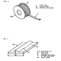
Fig. 1 is an oblique view showing an example of a nonmetallic twist tie of the present invention which is wound in a long size in a bundle form. -
Fig. 2 is an oblique view showing an example of a nonmetallic twist tie of the present invention which is prepared by an extrusion molding. -
Fig. 3 is an oblique view showing an example of a nonmetallic twist tie of the present invention which is prepared by a lamination molding. -
Fig. 4 is an oblique view showing an example of a binding machine in which the nonmetallic twist tie of the present invention is used. -
Fig. 5 is a drawing for an example of use of the nonmetallic twist tie of the present invention where a torsion property is shown. -
Fig. 6 is a rough drawing of a method for the measurement when a torsion strength (binding force) of the nonmetallic twist tie of the present invention is measured. -
Fig. 7 is a rough drawing of a method for the measurement when a property of forming a fixed shape and a property of retaining a fixed shape of the nonmetallic twist tie of the present invention are measured. -
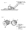
Fig. 8 is a rough drawing of a method for the measurement of a degree of curving to the drawing-out direction when the nonmetallic twist tie of the present invention is drawn out from a wound shape. -
Fig. 9 is a rough drawing of a method for the measurement of curling radius to the wound direction when the nonmetallic twist tie of the present invention is drawn out from a wound shape. - Generally, the
nonmetallic twist tie 1 of the present invention takes a form ofnonmetallic twist tie 1a in an extrusion molding type as shown inFig. 2 or takes a form ofnonmetallic twist tie 1b in a lamination type as shown inFig. 3 . Theformer tie 1a is able to be prepared, for example, by extrusion of a compounded composition where a non-halogenous resin is a main component into a shape havingcore part 3 and wing part 4 to conduct an extrusion integral molding while thelatter tie 1b is able to be prepared, for example, by making a non-halogenousplastic core line 5 intrinsic incore part 3 and by layering, on upside and downside thereof, acoating material 6 of a plastic film constituted from a non-halogenous resin or acoating material 6 such as paper or nonwoven fabric where said film is laminated in the inner surface thereof to conduct a lamination molding. Thosenonmetallic twist ties 1a/1b are supplied in a state as shown inFig. 1 where they are wound in a long size in a bundle form on a winding jig (reel). - The
nonmetallic twist tie 1 of the present invention is applied, for example, to abinding machine 11 as shown inFig. 4 whereby the use in awound state 2 of as long as, for example, about 500 m to 5,000 m is made possible although there is no particular limitation for the length. For such a purpose, it goes without saying that the binding ability upon binding by abinding machine 11 such as a torsion strength (expressed by a binding force measured by a method as shown inFig. 6 ) in a torsion state as shown, for example, inFig. 5 is to be excellent and, moreover, in awound shape 2 such as winding on a reel, occurrences of slipping down of thetie 1 into gap of areel 2a, torsion and curl of thetie 1, twining and tangling ofties 1 or loosening or disjoining oftie 1 from thereel 2a is not preferred and they should have been solved. - When a
nonmetallic twist tie 1 is wound in a bundle form such a wound around a reel or the like, the phenomena such as slipping down of thebound tie 1 into gap of areel 2a, torsion and curl of the tie itself, twining and tangling ofties 1 or loosening or disjoining oftie 1 from thereel 2a are apt to happen upon winding, transportation and use. - As a result, when slipping down of the twist tie 1 into gap of a reel, torsion thereof, or twining and tangling of the
twist ties 1 happens for example, an unequal resistance is resulted in thetwist tie 1 upon drawing out from awound state 2 whereby there is resulted an inconvenience such as curving of the twist tie to left or to right. - Further, curl of the
twist tie 1 results in a curl in the winding direction of thereel 2a causing a binding mistake. - On the other hand, disjoining and loosening of the
twist tie 1 in awound shape 2 due to poor property of forming a fixed shape and poor property of retaining a fixed shape of thetwist tie 1 are the causes for difficulty in twist in the binding using a binding machine or for breakage of the wing. - The present inventors have intensively carried out studies for solving those problems and, as a result, they have found that, when curving degree α upon drawing-out of the
twist tie 1 and curl radius r to a winding direction are controlled within a predetermined range, a good state of drawing out causing no induction of binding mistake is able to be achieved. - Thus, as shown in
Fig. 8 , it is necessary that a curving degree a to left and to right against the drawing-out direction is kept within 10°. The reason is that, when the curving degree is more than 10°, it often happens that the tie is not well held by abinding machine 11 resulting in a binding mistake. - It is also necessary that a curl radius r to the winding direction is to be within a range of 50 to 200 mm. The reasons is that there are many cases that, when it is more than 200 mm, an upward curvature occurs and a continuous binding by a
binding machine 11 is difficult while, when it is less than 50 mm, a downward curvature occurs resulting in troubles for a continuous binding by abinding machine 11. - On the other hand, when difficulty in twist in the binding using a
binding machine 11 and breakage of the wing were investigated, frequency for finding such inconveniences was very low in thetwist tie 1 where a torsion strength (i.e. a binding force) was within a range of 5 to 15 N. - On the basis of the findings of the studies as such, the present inventors have further investigated the shape of a
bound tie 1 where falling down of atwist tie 1 in awound form 2 into a gap of areel 2a, torsion thereof and twining and tangling ofties 1 hardly take place. - The result was that, in a
twist tie 1 where falling down, torsion, twining and tangling hardly occur, its total width (w inFig. 2 andFig. 3 ) is within a range of 1.50 to 20.0 mm and, more preferably, 2.5 to 20.0 mm. - When the total width w is narrower than 1.50 mm, function of the wing part 4 of the
twist tie 1 was hardly achieved and frequency of dropping, torsion, twining and tangling increased. When it is wider than 20 mm, width of the wing part 4 also expanded and there were many cases of causing troubles for torsion binding of thetwist tie 1. - When the thickness of the wing part 4 was investigated, the maximum thickness of the wing part 4 was appropriate to be 0.02 to 0.2 mm and, more preferably, 0.03 to 0.2 mm.
- When thickness of the wing part 4 was thinner than 0.02 mm, the effect as the wing part 4 was hardly achieved and, for example, falling into a gap of the
reel 2a by oscillation took place. When it was thicker than 0.2 mm, there was a problem such a breakage of the wing upon binding. - Then the
core part 3 was investigated and the maximum thickness h of thecore part 3 was found to be taken into consideration with regard to the total width w. - Thus, in view of stability and of easy binding of the twist tie 1 upon making into a
wound shape 2, it was found to be necessary that the maximum thickness h (height) of thecore part 3 was to be made thick when the width w became big while, when the width w became narrow, it was to be made thin. - As a result of further investigation about that, it was found that both winding property and binding property were satisfied to the best extent when the maximum thickness h of the
core part 3 was 0.04- to 0.30-fold or, more preferably, 0.05-to 0.25-fold of the total width w of thetwist tie 1. - When the maximum thickness h of the
core part 3 was less than 0.04-fold to the total width w, the shape was nearly in plate and a stable state was available in winding while, in view of binding, fulcrum for the torsion became wide whereby it was hardly twisted and poor binding was apt to be resulted. - On the other hand, when the maximum thickness h was more than 0.3-fold to the total width w, although that was good in terms of a good binding, state of the
wound shape 2 became unstable because thecore part 3 was projected in winding and, as a result, thetwist tie 1 was apt to slip during winding whereby there was a possibility of resulting in falling into the gap and twining and tangling ofties 1. - Although it is possible to make the shape of the
core part 3 into convex on one side as shown inFig. 2 particularly in view of consideration in thewound shape 2, there is no necessity to insist on that shape but the conclusion is that it is acceptable to have a thickness h in 0.04- to 0.3-fold to the total width w. - Then the present inventors investigated a phenomenon where disjoining and loosening are apt to occur in a
bound tie 1 in awound shape 2. As a result, it was found that, in order not to cause disjoining and loosening, it is necessary to give 90% or more property of forming a fixed shape and 7.0 to. 95% of property of retaining a fixed shape to thebound tie 1. - Further, when an investigation was conducted for a torsion strength in order not to cause a binding mistake in binding, the
twist tie 1 having a binding property (torsion strength) of 5 to 15 N showed the least binding mistake. - The property of forming a fixed shape, property of retaining a fixed shape and binding property within the aforementioned numeral range were achieved in a
twist tie 1 where a tensile elasticity was 5,000 to 30,000 Mpa. - The tensile elasticity is able to be obtained by any of the followings. They are (1) the use of a plastic core material 5 (
Fig. 3 ) which is highly elongated to an extent of 10-fold or more and (b) an extrusion molding of a compounded substance to which a filler is added followed by subjecting to an elongation of 2.5-fold or more (Fig. 2 ). - With regard to a torsion strength (binding force), the preferred one in a mechanical binding was 5 to 15 N. In other words, when the torsion strength (binding force) was less than 5 N, there was a binding mistake such as a loosening immediately after binding in a mechanical binding. In the case of more than 15 N where a strong load was applied upon the torsion, load was applied to a machine whereby an undesired binding state was noted such as that the bound part was in a shape of being bunched up together.
- In addition, when the torsion strength (biding force) was less than 5 N, there was a problem in a function as a
twist tie 1 such as a slipping off from a thing to be bound 7 or a disjointing by a mere weak force. In the case of more than 15 N, although there as no problem in a binding force, disjointing was poor as a result of too tight binding whereby there was a disadvantage of difficulty in recycling. - Now, property of retaining a fixed shape will be illustrated. When the property of retaining a fixed shape was less than 70%, there were many cases where disjoining of the
tie 1 from thereel 2a was induced while, when it was more than 95%, the recovering force is poor whereby frequency of slipping down into the gap and tangling and twining of the lines was much. - In a
twist tie 1 where the property of forming a fixed shape was less than 90%, it was hardly aligned with thereel 2a or the like in winding and, in addition, repulsive property of thetie 1 itself was big whereby falling into thereel 2a or tangling or twining is resulted. - Now, materials of the twist tie of the present invention will be illustrated by dividing into a
nonmetallic twist tie 1a of an extrusion molding type as shown inFig. 2 (hereinafter, referred to as an extrusion tie) and anonmetallic twist tie 1b of a lamination molding type as shown inFig. 3 (hereinafter, referred to as a lamination tie). - An
extrusion tie 1a comprises a compounded composition where a non-halogenous thermoplastic resin is a main component and, with regard to the thermoplastic resin, there is used one member selected from the group consisting of a polyester resin such as polyethylene terephthalate and polybutylene terephthalate, a polyamide resin such asNylon 6 and Nylon 66, a polyacetal resin such as polyvinyl formal and polyvinyl butyral, a polyolefin resin such as polyethylene and polypropylene, an acetate resin such as acetylcellulose, a polyvinyl resin such as Vinylon, starch, a biodegradable resin such as polylactic acid, a regenerated cellulose resin such as rayon, an acrylate resin such as polyacrylonitrile and a copolymer of polyacrylonitrile with acrylate monomer, a polycarbonate resin, a polyphenylene sulfide resin, etc. or a mixture of two or more members thereof. - In addition to the aforementioned thermoplastic resin, the
extrusion tie 1a is composed of a compounded substance in which silicic acid represented by white carbon, aluminum silicate represented by clay, magnesium silicate represented by talc, a silicate represented by silicic acid compound such as mica powder, a carbonate represented by calcium carbonate and magnesium carbonate, a metal oxide represented by calcium oxide, magnesium oxide, zinc oxide and titanium oxide, a metal hydroxide represented by magnesium hydroxide and aluminum hydroxide, a filler such as barium sulfate and carbon black, a lubricant such as stearic acid and zinc stearate, a plasticizers of a trimellitate type, a phthalate type, a fumarate type, an adipate type, an azelate type, a sebacate type, a polyester type and a stearate type, pigment, etc. are appropriately selected and added thereto upon necessity. - In view of a shape, there is a difference in the thickness between the
core part 3 and the wing part 4 and the reason therefor is that, due to the difference in the thickness, rigidity is given to thecore part 3 while flexibility is given to the wing part 4. InFig. 2 , the shape of thecore part 3 is shown in a convex on one side but it goes without saying that the shape of thecore part 3 is not limited thereto but it may be in convexes on both sides and what is important is that there is a predetermined difference between the thickness of thecore part 3 and that of the wing part 4. In the attached drawings, thecore part 3 is located nearly at the central part but the position is not always limited to the central part but may be at the end. The number thereof is not also limited to one but each one may be formed on both ends or plural ones may be formed at desired places. - Further, in the
extrusion tie 1a, it is also possible for further enhancing the rigidity of thecore part 3 that thecore part 3 and the wing part 4 are made in different compoundings and an extrusion molding is conducted using a biaxial extruder. - On the other hand; the
lamination tie 1b has a constitution where aplastic core material 5 comprising a non-halogenous resin being easily subjected to a plastic deformation is inserted between two sheets ofcoating materials 6 acting as a wing part and comprising paper, nonwoven fabric or the like where a thermoplastic resin such as plastic film or PE comprising a non-halogenous resin is laminated in the inner surface thereof. With regard to the plastic film comprising non-halogenous resin, an olefin film such as PE and PP, a polyolefin terephthalate film such as PET and PBT, an acetate film or a film comprising layered product thereof or a film using the above as a base on which metal is vapor-deposited having a thickness of 10 to 100 µ is mostly used although they are non-limitative but anything which is able to retain a property as a wing part may be used. Two coating materials which are laminated may be same or they may be different such as paper and PET film. - With regard to the
core material 5, a preferably used one is fine plastic lines comprising non-halogenous resin which is easily able to be subjected to a plastic deformation having a diameter of 0.3 to 1.8 mm, being highly elongated to an extent of 10-fold or more and mainly comprising a polyolefin resin such as polyethylene and polypropylene, a polyolefin terephthalate resin such as polybutylene terephthalate and polyethylene terephthalate, a polyamide resin or the like. - The
twist tie 1 of the present invention which is prepared as such is able to be bound using a bindingmachine 11 as shown inFig. 4 for example. In the bindingmachine 11 ofFig. 4 , an open part of a bag-shaped thing to be bound as shown inFig. 5 for example is inserted into a bindinggroove 13 of the main body of the bindingmachine 11 whereupon a continuous binding is conducted. In thetwist tie 1 of the present invention, it has a property necessary for the binding and its drawing out from thewound shape 2 is stabilized and, therefore, even in an operation with a speed of as high as 50 to 100 times per minute, a binding mistake is able to be suppressed to a minimum extent. - The
twist tie 1 of the present invention is used in a wound form as mentioned above and, besides that, it is also possible to use for a hand twisting for the use in gardening in such a form that the tie is drawn out from the wound form and cut in a predetermined length. In the case of a previously cut product which is produced for the use of hand twisting, a slitting operation or a cutting operation from big winding, medium winding or small winding is able to be smoothly carried during the step thereof because of the aforementioned good winding property and drawing-out property whereby it is possible to afford a cut product having a beautiful finish and a low production cost. - As shown in
Fig. 6 , aloop part 8 of thetwist tie 1 after pulling out from the thing to be bound 7 is cut at the position opposite to thebound part 9 and used as a sample. - In the measurement, the loop ends formed by cutting are set on the upper and lower fasteners of the tensile tester and pulled at the rate of 300 mm/minute to measure a binding force. Method for the Calculation of Property of Forming a Fixed Shape and Property of Retaining a Fixed Shape
- Property of forming a fixed shape and property of retaining a fixed shape (retaining state to a wound form) are calculated by the following formulae.
- Property of forming a fixed shape (easiness in bending)

- Property of retaining a fixed shape (easiness in rounding)

- l :
- Distance between the Marked Lines
- l0 :
- Straight-Line Distance between the Marked Lines upon Non-Loading
(Measured Thickness of the Dial Gauge upon Non-Loading - Thickness of Sample x 2) - l1 :
- Straight-Line Distance between the Marked Lines upon Loading
(Measured Thickness of the Dial Gauge upon Loading - Thickness of Sample x 2) - l2 :
- Straight-Line Distance between the Marked Lines Immediately after Being Allowed
- l3 :
- Straight-Line Distance between the Marked Lines after Being Allowed for 2 Minutes
- Method for the Measurement of Property of Forming a Fixed Shape and Property of Retaining a Fixed Shape
- As shown in
Fig. 7 , (1) atwist tie 1 collected from a wound form in a bundle is cut in a length of 80 mm precisely to prepare a sample and marked lines M having apredetermined distance 1 between the lines are formed at the central position of the sample (Fig. 7a ), (2) the sample is mildly bent so as to align the ends, the site of the marked lines M is sandwiched with adial gauge 14 having a measuring load of 80 g as stipulated by JIS Z 0237 (JIS B 7503), a straight-line distance between the marked lines upon non-loading (l0) and a straight-line distance between the marked lines upon loading (l1) are read from the graduation of thedial gauge 14 and a property of forming a fixed shape is determined from the aforementioned formula (Fig. 7b ) and then (3) thedial gauge 14 is removed, the straight-line distance between the marked lines immediately after being allowed (l2) is measured by a carpenter's square followed by measuring the straight-line distance between the marked lines after 2 minutes (l3) and a property of retaining the fixed shape is measured by the aforementioned formula (Fig. 7c ). - As shown in
Fig. 8 , degree of curving to the drawing-out direction of thetwist tie 1 when thetwist tie 1 in a wound state in a bundle is measured. Thus, thetie 1 is drawn out from a the wound state in a bundle to an extent of about 20 cm length and athick paper 15 for the measurement of degree of curving is attached as shown in the drawing and aligned to any of lines shown on thethick paper 15 to measure the degree of curving of the tie drawing out from the wound state in a bundle. - With regard to the measurement of the curl radius, a curl radius r to the wound direction is measured as shown in
Fig. 9 . Thus, a length corresponding to one round is mildly rewind from a wound state in a bundle and then cut. A previously preparedthick paper 16 having arcs for the measurement of curl radius is used, the surrounding of the sample is aligned to the corresponding arc of thethick paper 16 and the radius r to the arc is defined as theradius 5 of the curl. - Extrusion was carried out using the composition mentioned in the compounding example for the extrusion tie as shown in Table 1 followed by subjecting to an elongation for 3-fold to prepare a twist tie having the shape as shown in
Fig. 2 . This was wound in about 1,000 m in a form of a bundle to prepare extrusion tie samples A-1 to A-6. Results of measurement for size, shape and property of the samples are as shown in Table 3. Each sample was subj ected to a binding machine and subj ected to a practical test and the results thereof are as shown in Table 4. - For each of the PE core lines (a to e) mentioned in Table 2, plural core lines were laminated using the coating material mentioned in the same Table 2 in such a manner that they were made to reside in the coating material in parallel and, after that, the product was slit in each width to prepare a lamination tie having a shape as shown in
Fig. 3 . This was then wound in about 1,000 m in a form of a bundle to prepare lamination tie samples B-1 to B-5. Results of measurement for size, shape and property of the samples are as shown in Table 3. Each sample was subjected to a binding machine and then to a practical test and the results thereof are as shown in Table 4.Table 1 Compounding Example of Extrusion Tie Compounded Composition Compounded Amount (part(s) by weight) Name of Manufacturing Company Polyethylene terephthalate (spa-1206) 90 Unitika Polyethylene resin (NUC, grade G) 10 Nippon Unicar Zinc stearate 0.1 Sakai Chemical Industry Barium sulfate 10 Sakai Chemical Industry Softener (Adekapol CLE-1000) 0.05 Asahi Denka Pigment (BMF-270, PBF-650-S) 0.1 Resino Color Industry 


- As noted from Table 3 and Table 4, the nonmetallic twist tie of the present invention has shape and property by which the necessary function inherent to a twist tie was able to be fully achieved. In addition, in its wound state in a bundle, it was noted to be able to give and retain a shape by which slipping down into a gap of a winding reel, torsion and curl of the tie itself, twining and tangling of ties and loosening or disjoining in a wound state were very rare. Moreover, drawing out upon binding a material to be bound and the binding property at that time were also well satisfactory.
- The nonmetallic twist tie of the present invention has the aforementioned constitution and, accordingly, it is able to achieve the following advantages.
- (1) When the tie is wound in a bundle form, slipping down into a gap of a reel, torsion and curl of the tie itself, twining and tangling of ties and loosening or disjoining from a wound state were rare and a smooth drawing out is able to be carried out.
- (2) The tie has all of properties which are necessary for a mechanical binding and mistake in a mechanical binding is very rare.
- (3) Safety in actual use is very high in such a respect that, for example, no metal wire is used.
- (4) The tie is constituted from a non-halogenous material and it is a product taking a due considering in "environment".
- (5) The tie is able to be developed to broad areas from a long-size winding for a mechanical winding to a cut product for a hand binding.
Claims (4)
- A ribbon-shaped nonmetallic twist tie having a core part and a wing part constituted from a non-halogenous material, the core part and wing part each extend the length of the tie, the tie having a total width of 1.5 to 20.0 mm, a maximum thickness of the wing part of 0.02 to 0.20 mm and a maximum thickness of the core part of 0.04 to 0.30-fold of the total width, characterized in that it is obtained by lamination molding with the use of a plastic core material which is highly elongated to an extent of 10-fold or more, or by extrusion molding of a compounded substance to which a filler is added followed by subjecting to an elongation of 2.5-fold or more, and in that it has a property of forming a fixed shape of 90% or more and a property of retaining a fixed shape of 70 to 95%.
- The nonmetallic twist tie according to claim 1, characterized in having a torsion strength of 5 to 15 N.
- The nonmetallic twist tie according to claim 1 or claim 2, characterized in having a tensile elasticity of 5,000 to 30,000 Mpa.
- The nonmetallic twist tie according to any one of claims 1 to 3, characterized in having a drawing-out property where a degree of curving to the drawing-out direction is 10° or less and a curl radius to the winding direction retains the range of 50 to 200 mm.
Applications Claiming Priority (1)
| Application Number | Priority Date | Filing Date | Title |
|---|---|---|---|
| PCT/JP2003/013144 WO2005035381A1 (en) | 2003-10-14 | 2003-10-14 | Non-metallic twist tie |
Publications (3)
| Publication Number | Publication Date |
|---|---|
| EP1674405A1 EP1674405A1 (en) | 2006-06-28 |
| EP1674405A4 EP1674405A4 (en) | 2007-11-28 |
| EP1674405B1 true EP1674405B1 (en) | 2010-09-01 |
Family
ID=34430874
Family Applications (1)
| Application Number | Title | Priority Date | Filing Date |
|---|---|---|---|
| EP03754110A Expired - Lifetime EP1674405B1 (en) | 2003-10-14 | 2003-10-14 | Non-metallic twist tie |
Country Status (10)
| Country | Link |
|---|---|
| US (1) | US7363686B2 (en) |
| EP (1) | EP1674405B1 (en) |
| JP (1) | JP4564448B2 (en) |
| CN (1) | CN1860070A (en) |
| AT (1) | ATE479604T1 (en) |
| AU (1) | AU2003272997A1 (en) |
| DE (1) | DE60334035D1 (en) |
| DK (1) | DK1674405T3 (en) |
| ES (1) | ES2348137T3 (en) |
| WO (1) | WO2005035381A1 (en) |
Families Citing this family (37)
| Publication number | Priority date | Publication date | Assignee | Title |
|---|---|---|---|---|
| US7887082B2 (en) | 2006-09-01 | 2011-02-15 | Wire Core Strap, Inc. | Reformable closure device strap |
| ES2486565T3 (en) * | 2008-04-21 | 2014-08-18 | Nv Bekaert Sa | Binding wire and clip clip with biodegradable coatings and method for decomposition |
| US20110038565A1 (en) * | 2008-04-21 | 2011-02-17 | Nv Bekaert Sa | Means for closing a bag having a degradable, biodegradable and/or compostable coating |
| US8439665B2 (en) * | 2009-09-30 | 2013-05-14 | Stratasys, Inc. | Ribbon liquefier for use in extrusion-based digital manufacturing systems |
| US8236227B2 (en) * | 2009-09-30 | 2012-08-07 | Stratasys, Inc. | Method for building three-dimensional models in extrusion-based digital manufacturing systems using tracked filaments |
| US8221669B2 (en) | 2009-09-30 | 2012-07-17 | Stratasys, Inc. | Method for building three-dimensional models in extrusion-based digital manufacturing systems using ribbon filaments |
| EP2501535B1 (en) * | 2009-11-19 | 2017-11-15 | Stratasys, Inc. | Encoded consumable filaments for use in additive manufacturing systems |
| US20110117268A1 (en) * | 2009-11-19 | 2011-05-19 | Stratasys, Inc. | Consumable materials having encoded markings for use with direct digital manufacturing systems |
| US9022769B2 (en) | 2010-07-22 | 2015-05-05 | Stratasys, Inc. | Multiple-zone liquefier assembly for extrusion-based additive manufacturing systems |
| US8647098B2 (en) | 2010-09-22 | 2014-02-11 | Stratasys, Inc. | Liquefier assembly for use in extrusion-based additive manufacturing systems |
| US8815141B2 (en) | 2010-09-22 | 2014-08-26 | Stratasys, Inc. | Method for building three-dimensional models with extrusion-based additive manufacturing systems |
| NL2005715C2 (en) * | 2010-11-18 | 2012-05-22 | Schutte Bagclosures B V | CLOSING METHOD AND CLOSURE. |
| US8399769B2 (en) | 2011-03-25 | 2013-03-19 | Jay Thomas Doll | Cable management system and method of use |
| WO2013035749A1 (en) * | 2011-09-09 | 2013-03-14 | 古河電気工業株式会社 | Dicing die bonding film packing structure and packing method |
| US9050753B2 (en) | 2012-03-16 | 2015-06-09 | Stratasys, Inc. | Liquefier assembly having inlet liner for use in additive manufacturing system |
| US9321609B2 (en) | 2012-12-07 | 2016-04-26 | Stratasys, Inc. | Filament drive mechanism for use in additive manufacturing system |
| US9233506B2 (en) | 2012-12-07 | 2016-01-12 | Stratasys, Inc. | Liquefier assembly for use in additive manufacturing system |
| US9403610B2 (en) * | 2013-02-05 | 2016-08-02 | Bedford Industries, Inc. | In-line tie articles and methods of manufacture and use |
| JP6104655B2 (en) * | 2013-03-14 | 2017-03-29 | ライオン・スペシャリティ・ケミカルズ株式会社 | Conductive cable ties |
| US9527240B2 (en) | 2013-03-15 | 2016-12-27 | Stratasys, Inc. | Additive manufacturing system and method for printing three-dimensional parts using velocimetry |
| US9950474B2 (en) | 2013-09-13 | 2018-04-24 | Statasys, Inc. | Additive manufacturing system and process with precision substractive technique |
| US9327447B2 (en) | 2013-10-04 | 2016-05-03 | Stratasys, Inc. | Liquefier assembly for additive manufacturing systems, and methods of use thereof |
| US10086564B2 (en) | 2013-10-04 | 2018-10-02 | Stratsys, Inc. | Additive manufacturing process with dynamic heat flow control |
| US10201931B2 (en) | 2013-10-04 | 2019-02-12 | Stratasys, Inc. | Additive manufacturing system and process with material flow feedback control |
| US10131131B2 (en) | 2013-10-04 | 2018-11-20 | Stratasys, Inc. | Liquefier assembly with multiple-zone plate heater assembly |
| US8914915B1 (en) | 2013-11-26 | 2014-12-23 | Lisa Alari | Decorative footwear system |
| US10244862B2 (en) | 2014-03-31 | 2019-04-02 | Eric Gallup | Bendable strap with detachable accessory |
| CA3017783C (en) * | 2016-03-14 | 2023-10-03 | Twist-Ease, Inc. | Twist-tie product |
| US11261323B2 (en) | 2017-08-24 | 2022-03-01 | Banemer, LLC | Conformable thermoplastic compositions and articles |
| US10906699B2 (en) | 2017-08-24 | 2021-02-02 | Banemer, LLC | Non-metallic tie |
| US10984682B2 (en) | 2019-02-26 | 2021-04-20 | Bedford Industries, Inc. | Product piercing tag |
| WO2021022007A1 (en) * | 2019-07-31 | 2021-02-04 | Twist-Ease, Inc. | Biodegradable fastener |
| US11549782B2 (en) | 2019-11-08 | 2023-01-10 | Tech Dek Products Llc | Holster with bendable strap |
| USD1012687S1 (en) * | 2020-05-19 | 2024-01-30 | Schutte Bagclosures B.V. | Twist-tie for closing packages |
| CN112875430A (en) * | 2020-12-31 | 2021-06-01 | 协讯电子(吉安)有限公司 | Degradable paper bayonet cable bearing structure |
| CN113753289B (en) * | 2021-09-30 | 2022-12-13 | 广东包庄科技有限公司 | Automatic unreeling method and unreeling seat based on packaging belt for coreless machine |
| FR3146783A1 (en) * | 2023-03-22 | 2024-09-27 | Capifil | Hand-cut tying wire profile, associated spool and staking tie. |
Family Cites Families (17)
| Publication number | Priority date | Publication date | Assignee | Title |
|---|---|---|---|---|
| JPS5734143Y2 (en) * | 1979-02-03 | 1982-07-28 | ||
| JPS5734143A (en) | 1980-08-08 | 1982-02-24 | Nippon Chem Ind Co Ltd:The | Rubber composition |
| US4525898A (en) * | 1983-08-11 | 1985-07-02 | Tipper Tie, Inc. | Inverted tee cross section clip |
| JPS60190654A (en) | 1984-03-09 | 1985-09-28 | Nippon Carbureter Co Ltd | Air-fuel ratio control device for engine |
| JPS60190654U (en) * | 1984-05-29 | 1985-12-17 | 株式会社 共和 | wrapping string |
| US4797313A (en) * | 1985-11-08 | 1989-01-10 | Monsanto Company | Non-metallic polymeric twist tie |
| US5238631A (en) * | 1985-11-08 | 1993-08-24 | Kyowa Limited | Process of making non-metallic polymeric twist ties |
| JP2813994B2 (en) | 1989-10-06 | 1998-10-22 | 株式会社 共和 | Coreless twist tie and manufacturing method thereof |
| US5607748A (en) * | 1994-08-15 | 1997-03-04 | Bedford Industries, Inc. | Wireless polymeric twist tie |
| US5989683A (en) * | 1997-09-19 | 1999-11-23 | Bedford Industries, Inc. | Wireless polymeric twist tie |
| JP4009360B2 (en) | 1998-04-14 | 2007-11-14 | 株式会社共和 | Twist tie using plastic wire as core material |
| JP4338241B2 (en) | 1998-09-25 | 2009-10-07 | 株式会社共和 | Plastic bundling tie and manufacturing method thereof |
| JP4129327B2 (en) | 1998-10-16 | 2008-08-06 | 株式会社共和 | Packaging sheet and twist tie |
| JP2000203624A (en) | 1999-01-13 | 2000-07-25 | Akira Koto | Twist type binding tape |
| US6372068B1 (en) * | 1999-09-21 | 2002-04-16 | Roger S. Kincel | Composite polymeric twist tie |
| US7011879B1 (en) * | 1999-09-21 | 2006-03-14 | Johnston International Corp. | Composite polymeric twist tie |
| JP4049301B2 (en) | 2002-01-16 | 2008-02-20 | 信越ポリマー株式会社 | Twisted tie |
-
2003
- 2003-10-14 AU AU2003272997A patent/AU2003272997A1/en not_active Abandoned
- 2003-10-14 DK DK03754110.9T patent/DK1674405T3/en active
- 2003-10-14 ES ES03754110T patent/ES2348137T3/en not_active Expired - Lifetime
- 2003-10-14 DE DE60334035T patent/DE60334035D1/en not_active Expired - Lifetime
- 2003-10-14 AT AT03754110T patent/ATE479604T1/en not_active IP Right Cessation
- 2003-10-14 JP JP2005509478A patent/JP4564448B2/en not_active Expired - Fee Related
- 2003-10-14 CN CN200380110531.6A patent/CN1860070A/en active Pending
- 2003-10-14 US US10/574,428 patent/US7363686B2/en not_active Expired - Lifetime
- 2003-10-14 EP EP03754110A patent/EP1674405B1/en not_active Expired - Lifetime
- 2003-10-14 WO PCT/JP2003/013144 patent/WO2005035381A1/en not_active Ceased
Also Published As
| Publication number | Publication date |
|---|---|
| AU2003272997A1 (en) | 2005-04-27 |
| DK1674405T3 (en) | 2010-10-18 |
| US20070006426A1 (en) | 2007-01-11 |
| WO2005035381A1 (en) | 2005-04-21 |
| CN1860070A (en) | 2006-11-08 |
| JP4564448B2 (en) | 2010-10-20 |
| EP1674405A4 (en) | 2007-11-28 |
| ES2348137T3 (en) | 2010-11-30 |
| ATE479604T1 (en) | 2010-09-15 |
| JPWO2005035381A1 (en) | 2006-12-21 |
| US7363686B2 (en) | 2008-04-29 |
| EP1674405A1 (en) | 2006-06-28 |
| DE60334035D1 (en) | 2010-10-14 |
Similar Documents
| Publication | Publication Date | Title |
|---|---|---|
| EP1674405A1 (en) | Non-metallic twist tie | |
| JP2813994B2 (en) | Coreless twist tie and manufacturing method thereof | |
| US4451533A (en) | Dispensable polypropylene adhesive-coated tape | |
| EP1284907B1 (en) | Non-blocking drawtape bag | |
| EP0858419B1 (en) | Fixed circumference binding device with non-protruding free end | |
| US4150184A (en) | Tear-off band | |
| WO2018017213A1 (en) | Wire tie with adhesive | |
| US20160355365A1 (en) | Tape dispenser, cutting blade and method | |
| JP2016084140A (en) | Storage body of wrapping film roll | |
| JP3048540B2 (en) | Tying strap | |
| JP4338241B2 (en) | Plastic bundling tie and manufacturing method thereof | |
| EP2455298B1 (en) | Closure for closing a flexible packaging | |
| KR101045489B1 (en) | Nonmetal twist string | |
| US5634498A (en) | Lubricous flexible synthetic hose and method for producing same | |
| TWI300399B (en) | Non-metallic tie | |
| US11076995B2 (en) | Cold-drawn polyolefin copolymers cord for earplug | |
| JP2007011020A (en) | Fiber optic cable | |
| CA1044661A (en) | Binding material | |
| JP2019077456A (en) | Binding material | |
| JP5242801B2 (en) | Molding component | |
| HK1096360A (en) | Non-metallic twist tie | |
| JPH09207197A (en) | Method for forming thermoplastic resin pipe containing reinforcing strip and apparatus used therefor | |
| JPH111263A (en) | Twist tie | |
| JPH1053917A (en) | Polyethylene monofilament and its use | |
| JP2001341195A (en) | Shapeable plastic ribbon and molded product with the ribbon attached |
Legal Events
| Date | Code | Title | Description |
|---|---|---|---|
| PUAI | Public reference made under article 153(3) epc to a published international application that has entered the european phase |
Free format text: ORIGINAL CODE: 0009012 |
|
| 17P | Request for examination filed |
Effective date: 20060406 |
|
| AK | Designated contracting states |
Kind code of ref document: A1 Designated state(s): AT BE BG CH CY CZ DE DK EE ES FI FR GB GR HU IE IT LI LU MC NL PT RO SE SI SK TR |
|
| DAX | Request for extension of the european patent (deleted) | ||
| A4 | Supplementary search report drawn up and despatched |
Effective date: 20071025 |
|
| RIC1 | Information provided on ipc code assigned before grant |
Ipc: B65D 63/12 20060101ALI20071019BHEP Ipc: B65D 63/10 20060101AFI20050425BHEP |
|
| 17Q | First examination report despatched |
Effective date: 20080214 |
|
| GRAP | Despatch of communication of intention to grant a patent |
Free format text: ORIGINAL CODE: EPIDOSNIGR1 |
|
| GRAS | Grant fee paid |
Free format text: ORIGINAL CODE: EPIDOSNIGR3 |
|
| GRAA | (expected) grant |
Free format text: ORIGINAL CODE: 0009210 |
|
| AK | Designated contracting states |
Kind code of ref document: B1 Designated state(s): AT BE BG CH CY CZ DE DK EE ES FI FR GB GR HU IE IT LI LU MC NL PT RO SE SI SK TR |
|
| REG | Reference to a national code |
Ref country code: GB Ref legal event code: FG4D |
|
| REG | Reference to a national code |
Ref country code: CH Ref legal event code: EP |
|
| REG | Reference to a national code |
Ref country code: IE Ref legal event code: FG4D |
|
| REF | Corresponds to: |
Ref document number: 60334035 Country of ref document: DE Date of ref document: 20101014 Kind code of ref document: P |
|
| REG | Reference to a national code |
Ref country code: DK Ref legal event code: T3 |
|
| REG | Reference to a national code |
Ref country code: NL Ref legal event code: T3 |
|
| PG25 | Lapsed in a contracting state [announced via postgrant information from national office to epo] |
Ref country code: AT Free format text: LAPSE BECAUSE OF FAILURE TO SUBMIT A TRANSLATION OF THE DESCRIPTION OR TO PAY THE FEE WITHIN THE PRESCRIBED TIME-LIMIT Effective date: 20100901 Ref country code: FI Free format text: LAPSE BECAUSE OF FAILURE TO SUBMIT A TRANSLATION OF THE DESCRIPTION OR TO PAY THE FEE WITHIN THE PRESCRIBED TIME-LIMIT Effective date: 20100901 |
|
| PG25 | Lapsed in a contracting state [announced via postgrant information from national office to epo] |
Ref country code: SI Free format text: LAPSE BECAUSE OF FAILURE TO SUBMIT A TRANSLATION OF THE DESCRIPTION OR TO PAY THE FEE WITHIN THE PRESCRIBED TIME-LIMIT Effective date: 20100901 Ref country code: CY Free format text: LAPSE BECAUSE OF FAILURE TO SUBMIT A TRANSLATION OF THE DESCRIPTION OR TO PAY THE FEE WITHIN THE PRESCRIBED TIME-LIMIT Effective date: 20100901 |
|
| PG25 | Lapsed in a contracting state [announced via postgrant information from national office to epo] |
Ref country code: GR Free format text: LAPSE BECAUSE OF FAILURE TO SUBMIT A TRANSLATION OF THE DESCRIPTION OR TO PAY THE FEE WITHIN THE PRESCRIBED TIME-LIMIT Effective date: 20101202 Ref country code: SE Free format text: LAPSE BECAUSE OF FAILURE TO SUBMIT A TRANSLATION OF THE DESCRIPTION OR TO PAY THE FEE WITHIN THE PRESCRIBED TIME-LIMIT Effective date: 20100901 |
|
| PG25 | Lapsed in a contracting state [announced via postgrant information from national office to epo] |
Ref country code: RO Free format text: LAPSE BECAUSE OF FAILURE TO SUBMIT A TRANSLATION OF THE DESCRIPTION OR TO PAY THE FEE WITHIN THE PRESCRIBED TIME-LIMIT Effective date: 20100901 Ref country code: SK Free format text: LAPSE BECAUSE OF FAILURE TO SUBMIT A TRANSLATION OF THE DESCRIPTION OR TO PAY THE FEE WITHIN THE PRESCRIBED TIME-LIMIT Effective date: 20100901 Ref country code: EE Free format text: LAPSE BECAUSE OF FAILURE TO SUBMIT A TRANSLATION OF THE DESCRIPTION OR TO PAY THE FEE WITHIN THE PRESCRIBED TIME-LIMIT Effective date: 20100901 Ref country code: PT Free format text: LAPSE BECAUSE OF FAILURE TO SUBMIT A TRANSLATION OF THE DESCRIPTION OR TO PAY THE FEE WITHIN THE PRESCRIBED TIME-LIMIT Effective date: 20110103 Ref country code: CZ Free format text: LAPSE BECAUSE OF FAILURE TO SUBMIT A TRANSLATION OF THE DESCRIPTION OR TO PAY THE FEE WITHIN THE PRESCRIBED TIME-LIMIT Effective date: 20100901 Ref country code: MC Free format text: LAPSE BECAUSE OF NON-PAYMENT OF DUE FEES Effective date: 20101031 |
|
| REG | Reference to a national code |
Ref country code: CH Ref legal event code: PL |
|
| PG25 | Lapsed in a contracting state [announced via postgrant information from national office to epo] |
Ref country code: BE Free format text: LAPSE BECAUSE OF FAILURE TO SUBMIT A TRANSLATION OF THE DESCRIPTION OR TO PAY THE FEE WITHIN THE PRESCRIBED TIME-LIMIT Effective date: 20100901 |
|
| PLBE | No opposition filed within time limit |
Free format text: ORIGINAL CODE: 0009261 |
|
| STAA | Information on the status of an ep patent application or granted ep patent |
Free format text: STATUS: NO OPPOSITION FILED WITHIN TIME LIMIT |
|
| PG25 | Lapsed in a contracting state [announced via postgrant information from national office to epo] |
Ref country code: LI Free format text: LAPSE BECAUSE OF NON-PAYMENT OF DUE FEES Effective date: 20101031 Ref country code: CH Free format text: LAPSE BECAUSE OF NON-PAYMENT OF DUE FEES Effective date: 20101031 |
|
| 26N | No opposition filed |
Effective date: 20110606 |
|
| REG | Reference to a national code |
Ref country code: DE Ref legal event code: R097 Ref document number: 60334035 Country of ref document: DE Effective date: 20110606 |
|
| PG25 | Lapsed in a contracting state [announced via postgrant information from national office to epo] |
Ref country code: IE Free format text: LAPSE BECAUSE OF NON-PAYMENT OF DUE FEES Effective date: 20101014 |
|
| PG25 | Lapsed in a contracting state [announced via postgrant information from national office to epo] |
Ref country code: HU Free format text: LAPSE BECAUSE OF FAILURE TO SUBMIT A TRANSLATION OF THE DESCRIPTION OR TO PAY THE FEE WITHIN THE PRESCRIBED TIME-LIMIT Effective date: 20110302 Ref country code: LU Free format text: LAPSE BECAUSE OF NON-PAYMENT OF DUE FEES Effective date: 20101014 Ref country code: BG Free format text: LAPSE BECAUSE OF FAILURE TO SUBMIT A TRANSLATION OF THE DESCRIPTION OR TO PAY THE FEE WITHIN THE PRESCRIBED TIME-LIMIT Effective date: 20100901 |
|
| PG25 | Lapsed in a contracting state [announced via postgrant information from national office to epo] |
Ref country code: TR Free format text: LAPSE BECAUSE OF FAILURE TO SUBMIT A TRANSLATION OF THE DESCRIPTION OR TO PAY THE FEE WITHIN THE PRESCRIBED TIME-LIMIT Effective date: 20100901 |
|
| PG25 | Lapsed in a contracting state [announced via postgrant information from national office to epo] |
Ref country code: BG Free format text: LAPSE BECAUSE OF FAILURE TO SUBMIT A TRANSLATION OF THE DESCRIPTION OR TO PAY THE FEE WITHIN THE PRESCRIBED TIME-LIMIT Effective date: 20101201 |
|
| REG | Reference to a national code |
Ref country code: FR Ref legal event code: PLFP Year of fee payment: 13 |
|
| REG | Reference to a national code |
Ref country code: FR Ref legal event code: PLFP Year of fee payment: 14 |
|
| REG | Reference to a national code |
Ref country code: FR Ref legal event code: PLFP Year of fee payment: 15 |
|
| REG | Reference to a national code |
Ref country code: FR Ref legal event code: PLFP Year of fee payment: 16 |
|
| PGFP | Annual fee paid to national office [announced via postgrant information from national office to epo] |
Ref country code: FR Payment date: 20210820 Year of fee payment: 19 |
|
| PGFP | Annual fee paid to national office [announced via postgrant information from national office to epo] |
Ref country code: GB Payment date: 20210816 Year of fee payment: 19 |
|
| PGFP | Annual fee paid to national office [announced via postgrant information from national office to epo] |
Ref country code: DK Payment date: 20211025 Year of fee payment: 19 |
|
| PGFP | Annual fee paid to national office [announced via postgrant information from national office to epo] |
Ref country code: NL Payment date: 20220930 Year of fee payment: 20 |
|
| PGFP | Annual fee paid to national office [announced via postgrant information from national office to epo] |
Ref country code: DE Payment date: 20221027 Year of fee payment: 20 Ref country code: IT Payment date: 20220908 Year of fee payment: 20 Ref country code: ES Payment date: 20221102 Year of fee payment: 20 |
|
| REG | Reference to a national code |
Ref country code: DK Ref legal event code: EBP Effective date: 20221031 |
|
| GBPC | Gb: european patent ceased through non-payment of renewal fee |
Effective date: 20221014 |
|
| PG25 | Lapsed in a contracting state [announced via postgrant information from national office to epo] |
Ref country code: FR Free format text: LAPSE BECAUSE OF NON-PAYMENT OF DUE FEES Effective date: 20221031 |
|
| REG | Reference to a national code |
Ref country code: DE Ref legal event code: R071 Ref document number: 60334035 Country of ref document: DE |
|
| REG | Reference to a national code |
Ref country code: NL Ref legal event code: MK Effective date: 20231013 |
|
| REG | Reference to a national code |
Ref country code: ES Ref legal event code: FD2A Effective date: 20231027 |
|
| PG25 | Lapsed in a contracting state [announced via postgrant information from national office to epo] |
Ref country code: GB Free format text: LAPSE BECAUSE OF NON-PAYMENT OF DUE FEES Effective date: 20221014 Ref country code: DK Free format text: LAPSE BECAUSE OF NON-PAYMENT OF DUE FEES Effective date: 20221031 |
|
| PG25 | Lapsed in a contracting state [announced via postgrant information from national office to epo] |
Ref country code: ES Free format text: LAPSE BECAUSE OF EXPIRATION OF PROTECTION Effective date: 20231015 |
|
| PG25 | Lapsed in a contracting state [announced via postgrant information from national office to epo] |
Ref country code: ES Free format text: LAPSE BECAUSE OF EXPIRATION OF PROTECTION Effective date: 20231015 |