EP2501535B1 - Encoded consumable filaments for use in additive manufacturing systems - Google Patents
Encoded consumable filaments for use in additive manufacturing systems Download PDFInfo
- Publication number
- EP2501535B1 EP2501535B1 EP10784631.3A EP10784631A EP2501535B1 EP 2501535 B1 EP2501535 B1 EP 2501535B1 EP 10784631 A EP10784631 A EP 10784631A EP 2501535 B1 EP2501535 B1 EP 2501535B1
- Authority
- EP
- European Patent Office
- Prior art keywords
- filament
- encoded
- markings
- information
- consumable
- Prior art date
- Legal status (The legal status is an assumption and is not a legal conclusion. Google has not performed a legal analysis and makes no representation as to the accuracy of the status listed.)
- Active
Links
- 238000004519 manufacturing process Methods 0.000 title claims description 48
- 239000000654 additive Substances 0.000 title claims description 42
- 230000000996 additive effect Effects 0.000 title claims description 39
- 239000000463 material Substances 0.000 claims description 166
- 238000001125 extrusion Methods 0.000 claims description 68
- 239000002243 precursor Substances 0.000 claims description 46
- 238000000034 method Methods 0.000 claims description 43
- 230000003287 optical effect Effects 0.000 claims description 29
- 230000000717 retained effect Effects 0.000 claims description 29
- 239000000203 mixture Substances 0.000 claims description 20
- 238000000576 coating method Methods 0.000 claims description 15
- 238000000151 deposition Methods 0.000 claims description 8
- 239000012815 thermoplastic material Substances 0.000 claims description 5
- 239000003086 colorant Substances 0.000 claims description 3
- 238000005259 measurement Methods 0.000 claims description 3
- 238000002844 melting Methods 0.000 claims 1
- 230000008018 melting Effects 0.000 claims 1
- 230000037361 pathway Effects 0.000 description 25
- 238000000429 assembly Methods 0.000 description 21
- 230000000712 assembly Effects 0.000 description 21
- 238000004891 communication Methods 0.000 description 17
- 230000004323 axial length Effects 0.000 description 13
- 238000000608 laser ablation Methods 0.000 description 10
- 238000005286 illumination Methods 0.000 description 9
- 239000008188 pellet Substances 0.000 description 9
- 230000008569 process Effects 0.000 description 9
- 230000004888 barrier function Effects 0.000 description 8
- 230000009477 glass transition Effects 0.000 description 8
- 238000004132 cross linking Methods 0.000 description 5
- 230000009286 beneficial effect Effects 0.000 description 4
- -1 cycloalkyl phthalates Chemical class 0.000 description 4
- 238000003384 imaging method Methods 0.000 description 4
- 230000007246 mechanism Effects 0.000 description 4
- 230000000704 physical effect Effects 0.000 description 4
- VYPSYNLAJGMNEJ-UHFFFAOYSA-N Silicium dioxide Chemical compound O=[Si]=O VYPSYNLAJGMNEJ-UHFFFAOYSA-N 0.000 description 3
- 230000006835 compression Effects 0.000 description 3
- 238000007906 compression Methods 0.000 description 3
- 238000005336 cracking Methods 0.000 description 3
- 230000008021 deposition Effects 0.000 description 3
- 239000011521 glass Substances 0.000 description 3
- 238000007373 indentation Methods 0.000 description 3
- 239000007769 metal material Substances 0.000 description 3
- 239000000758 substrate Substances 0.000 description 3
- VTYYLEPIZMXCLO-UHFFFAOYSA-L Calcium carbonate Chemical compound [Ca+2].[O-]C([O-])=O VTYYLEPIZMXCLO-UHFFFAOYSA-L 0.000 description 2
- 241000237858 Gastropoda Species 0.000 description 2
- PEDCQBHIVMGVHV-UHFFFAOYSA-N Glycerine Chemical compound OCC(O)CO PEDCQBHIVMGVHV-UHFFFAOYSA-N 0.000 description 2
- 239000004676 acrylonitrile butadiene styrene Substances 0.000 description 2
- 239000002131 composite material Substances 0.000 description 2
- 229920001577 copolymer Polymers 0.000 description 2
- 238000010586 diagram Methods 0.000 description 2
- 238000001704 evaporation Methods 0.000 description 2
- 230000008020 evaporation Effects 0.000 description 2
- 239000000945 filler Substances 0.000 description 2
- 238000010330 laser marking Methods 0.000 description 2
- 239000000155 melt Substances 0.000 description 2
- 238000009304 pastoral farming Methods 0.000 description 2
- 239000004033 plastic Substances 0.000 description 2
- 229920003023 plastic Polymers 0.000 description 2
- 239000004014 plasticizer Substances 0.000 description 2
- 239000005995 Aluminium silicate Substances 0.000 description 1
- 101100478290 Arabidopsis thaliana SR30 gene Proteins 0.000 description 1
- OKTJSMMVPCPJKN-UHFFFAOYSA-N Carbon Chemical compound [C] OKTJSMMVPCPJKN-UHFFFAOYSA-N 0.000 description 1
- 229920000049 Carbon (fiber) Polymers 0.000 description 1
- 229910019142 PO4 Inorganic materials 0.000 description 1
- 229920000491 Polyphenylsulfone Polymers 0.000 description 1
- 239000004793 Polystyrene Substances 0.000 description 1
- 238000010521 absorption reaction Methods 0.000 description 1
- XECAHXYUAAWDEL-UHFFFAOYSA-N acrylonitrile butadiene styrene Chemical compound C=CC=C.C=CC#N.C=CC1=CC=CC=C1 XECAHXYUAAWDEL-UHFFFAOYSA-N 0.000 description 1
- 229920000122 acrylonitrile butadiene styrene Polymers 0.000 description 1
- 230000009471 action Effects 0.000 description 1
- WNLRTRBMVRJNCN-UHFFFAOYSA-N adipic acid Chemical class OC(=O)CCCCC(O)=O WNLRTRBMVRJNCN-UHFFFAOYSA-N 0.000 description 1
- PNEYBMLMFCGWSK-UHFFFAOYSA-N aluminium oxide Inorganic materials [O-2].[O-2].[O-2].[Al+3].[Al+3] PNEYBMLMFCGWSK-UHFFFAOYSA-N 0.000 description 1
- 235000012211 aluminium silicate Nutrition 0.000 description 1
- 229920006020 amorphous polyamide Polymers 0.000 description 1
- QVZZPLDJERFENQ-NKTUOASPSA-N bassianolide Chemical compound CC(C)C[C@@H]1N(C)C(=O)[C@@H](C(C)C)OC(=O)[C@H](CC(C)C)N(C)C(=O)[C@@H](C(C)C)OC(=O)[C@H](CC(C)C)N(C)C(=O)[C@@H](C(C)C)OC(=O)[C@H](CC(C)C)N(C)C(=O)[C@@H](C(C)C)OC1=O QVZZPLDJERFENQ-NKTUOASPSA-N 0.000 description 1
- 125000001797 benzyl group Chemical group [H]C1=C([H])C([H])=C(C([H])=C1[H])C([H])([H])* 0.000 description 1
- 230000015572 biosynthetic process Effects 0.000 description 1
- 229910000019 calcium carbonate Inorganic materials 0.000 description 1
- QXJJQWWVWRCVQT-UHFFFAOYSA-K calcium;sodium;phosphate Chemical compound [Na+].[Ca+2].[O-]P([O-])([O-])=O QXJJQWWVWRCVQT-UHFFFAOYSA-K 0.000 description 1
- 239000006229 carbon black Substances 0.000 description 1
- 239000004917 carbon fiber Substances 0.000 description 1
- 238000003486 chemical etching Methods 0.000 description 1
- 150000001860 citric acid derivatives Chemical class 0.000 description 1
- 239000011248 coating agent Substances 0.000 description 1
- 230000000295 complement effect Effects 0.000 description 1
- 238000010276 construction Methods 0.000 description 1
- 238000010924 continuous production Methods 0.000 description 1
- 239000002274 desiccant Substances 0.000 description 1
- 150000002148 esters Chemical class 0.000 description 1
- 230000009969 flowable effect Effects 0.000 description 1
- 239000003365 glass fiber Substances 0.000 description 1
- 235000011187 glycerol Nutrition 0.000 description 1
- 239000010439 graphite Substances 0.000 description 1
- 229910002804 graphite Inorganic materials 0.000 description 1
- 238000005468 ion implantation Methods 0.000 description 1
- 230000001788 irregular Effects 0.000 description 1
- NLYAJNPCOHFWQQ-UHFFFAOYSA-N kaolin Chemical compound O.O.O=[Al]O[Si](=O)O[Si](=O)O[Al]=O NLYAJNPCOHFWQQ-UHFFFAOYSA-N 0.000 description 1
- ZLNQQNXFFQJAID-UHFFFAOYSA-L magnesium carbonate Chemical compound [Mg+2].[O-]C([O-])=O ZLNQQNXFFQJAID-UHFFFAOYSA-L 0.000 description 1
- 239000001095 magnesium carbonate Substances 0.000 description 1
- 229910000021 magnesium carbonate Inorganic materials 0.000 description 1
- 230000000873 masking effect Effects 0.000 description 1
- VNWKTOKETHGBQD-UHFFFAOYSA-N methane Chemical compound C VNWKTOKETHGBQD-UHFFFAOYSA-N 0.000 description 1
- 239000010445 mica Substances 0.000 description 1
- 229910052618 mica group Inorganic materials 0.000 description 1
- 230000004048 modification Effects 0.000 description 1
- 238000012986 modification Methods 0.000 description 1
- 239000012768 molten material Substances 0.000 description 1
- 235000021317 phosphate Nutrition 0.000 description 1
- 125000005498 phthalate group Chemical class 0.000 description 1
- 229920002492 poly(sulfone) Polymers 0.000 description 1
- 239000004417 polycarbonate Substances 0.000 description 1
- 229920000515 polycarbonate Polymers 0.000 description 1
- 229920006393 polyether sulfone Polymers 0.000 description 1
- 229920001601 polyetherimide Polymers 0.000 description 1
- 229920001522 polyglycol ester Polymers 0.000 description 1
- 229920000642 polymer Polymers 0.000 description 1
- 229920002223 polystyrene Polymers 0.000 description 1
- 238000012805 post-processing Methods 0.000 description 1
- 239000010453 quartz Substances 0.000 description 1
- 238000004064 recycling Methods 0.000 description 1
- 239000006254 rheological additive Substances 0.000 description 1
- 239000004065 semiconductor Substances 0.000 description 1
- HBMJWWWQQXIZIP-UHFFFAOYSA-N silicon carbide Chemical compound [Si+]#[C-] HBMJWWWQQXIZIP-UHFFFAOYSA-N 0.000 description 1
- 229910010271 silicon carbide Inorganic materials 0.000 description 1
- 239000000377 silicon dioxide Substances 0.000 description 1
- 239000007787 solid Substances 0.000 description 1
- 239000003381 stabilizer Substances 0.000 description 1
- 238000003860 storage Methods 0.000 description 1
- 239000000454 talc Substances 0.000 description 1
- 229910052623 talc Inorganic materials 0.000 description 1
- 238000011144 upstream manufacturing Methods 0.000 description 1
- XLYOFNOQVPJJNP-UHFFFAOYSA-N water Substances O XLYOFNOQVPJJNP-UHFFFAOYSA-N 0.000 description 1
- 239000010456 wollastonite Substances 0.000 description 1
- 229910052882 wollastonite Inorganic materials 0.000 description 1
Images


Classifications
-
- B—PERFORMING OPERATIONS; TRANSPORTING
- B29—WORKING OF PLASTICS; WORKING OF SUBSTANCES IN A PLASTIC STATE IN GENERAL
- B29C—SHAPING OR JOINING OF PLASTICS; SHAPING OF MATERIAL IN A PLASTIC STATE, NOT OTHERWISE PROVIDED FOR; AFTER-TREATMENT OF THE SHAPED PRODUCTS, e.g. REPAIRING
- B29C64/00—Additive manufacturing, i.e. manufacturing of three-dimensional [3D] objects by additive deposition, additive agglomeration or additive layering, e.g. by 3D printing, stereolithography or selective laser sintering
- B29C64/10—Processes of additive manufacturing
- B29C64/106—Processes of additive manufacturing using only liquids or viscous materials, e.g. depositing a continuous bead of viscous material
-
- B—PERFORMING OPERATIONS; TRANSPORTING
- B29—WORKING OF PLASTICS; WORKING OF SUBSTANCES IN A PLASTIC STATE IN GENERAL
- B29B—PREPARATION OR PRETREATMENT OF THE MATERIAL TO BE SHAPED; MAKING GRANULES OR PREFORMS; RECOVERY OF PLASTICS OR OTHER CONSTITUENTS OF WASTE MATERIAL CONTAINING PLASTICS
- B29B11/00—Making preforms
- B29B11/14—Making preforms characterised by structure or composition
-
- B—PERFORMING OPERATIONS; TRANSPORTING
- B29—WORKING OF PLASTICS; WORKING OF SUBSTANCES IN A PLASTIC STATE IN GENERAL
- B29C—SHAPING OR JOINING OF PLASTICS; SHAPING OF MATERIAL IN A PLASTIC STATE, NOT OTHERWISE PROVIDED FOR; AFTER-TREATMENT OF THE SHAPED PRODUCTS, e.g. REPAIRING
- B29C49/00—Blow-moulding, i.e. blowing a preform or parison to a desired shape within a mould; Apparatus therefor
- B29C49/071—Preforms or parisons characterised by their configuration, e.g. geometry, dimensions or physical properties
-
- B—PERFORMING OPERATIONS; TRANSPORTING
- B29—WORKING OF PLASTICS; WORKING OF SUBSTANCES IN A PLASTIC STATE IN GENERAL
- B29C—SHAPING OR JOINING OF PLASTICS; SHAPING OF MATERIAL IN A PLASTIC STATE, NOT OTHERWISE PROVIDED FOR; AFTER-TREATMENT OF THE SHAPED PRODUCTS, e.g. REPAIRING
- B29C64/00—Additive manufacturing, i.e. manufacturing of three-dimensional [3D] objects by additive deposition, additive agglomeration or additive layering, e.g. by 3D printing, stereolithography or selective laser sintering
- B29C64/10—Processes of additive manufacturing
- B29C64/106—Processes of additive manufacturing using only liquids or viscous materials, e.g. depositing a continuous bead of viscous material
- B29C64/118—Processes of additive manufacturing using only liquids or viscous materials, e.g. depositing a continuous bead of viscous material using filamentary material being melted, e.g. fused deposition modelling [FDM]
-
- B—PERFORMING OPERATIONS; TRANSPORTING
- B29—WORKING OF PLASTICS; WORKING OF SUBSTANCES IN A PLASTIC STATE IN GENERAL
- B29C—SHAPING OR JOINING OF PLASTICS; SHAPING OF MATERIAL IN A PLASTIC STATE, NOT OTHERWISE PROVIDED FOR; AFTER-TREATMENT OF THE SHAPED PRODUCTS, e.g. REPAIRING
- B29C64/00—Additive manufacturing, i.e. manufacturing of three-dimensional [3D] objects by additive deposition, additive agglomeration or additive layering, e.g. by 3D printing, stereolithography or selective laser sintering
- B29C64/20—Apparatus for additive manufacturing; Details thereof or accessories therefor
-
- B—PERFORMING OPERATIONS; TRANSPORTING
- B29—WORKING OF PLASTICS; WORKING OF SUBSTANCES IN A PLASTIC STATE IN GENERAL
- B29C—SHAPING OR JOINING OF PLASTICS; SHAPING OF MATERIAL IN A PLASTIC STATE, NOT OTHERWISE PROVIDED FOR; AFTER-TREATMENT OF THE SHAPED PRODUCTS, e.g. REPAIRING
- B29C64/00—Additive manufacturing, i.e. manufacturing of three-dimensional [3D] objects by additive deposition, additive agglomeration or additive layering, e.g. by 3D printing, stereolithography or selective laser sintering
- B29C64/30—Auxiliary operations or equipment
- B29C64/386—Data acquisition or data processing for additive manufacturing
- B29C64/393—Data acquisition or data processing for additive manufacturing for controlling or regulating additive manufacturing processes
-
- B—PERFORMING OPERATIONS; TRANSPORTING
- B33—ADDITIVE MANUFACTURING TECHNOLOGY
- B33Y—ADDITIVE MANUFACTURING, i.e. MANUFACTURING OF THREE-DIMENSIONAL [3-D] OBJECTS BY ADDITIVE DEPOSITION, ADDITIVE AGGLOMERATION OR ADDITIVE LAYERING, e.g. BY 3-D PRINTING, STEREOLITHOGRAPHY OR SELECTIVE LASER SINTERING
- B33Y10/00—Processes of additive manufacturing
-
- B—PERFORMING OPERATIONS; TRANSPORTING
- B33—ADDITIVE MANUFACTURING TECHNOLOGY
- B33Y—ADDITIVE MANUFACTURING, i.e. MANUFACTURING OF THREE-DIMENSIONAL [3-D] OBJECTS BY ADDITIVE DEPOSITION, ADDITIVE AGGLOMERATION OR ADDITIVE LAYERING, e.g. BY 3-D PRINTING, STEREOLITHOGRAPHY OR SELECTIVE LASER SINTERING
- B33Y40/00—Auxiliary operations or equipment, e.g. for material handling
-
- B—PERFORMING OPERATIONS; TRANSPORTING
- B33—ADDITIVE MANUFACTURING TECHNOLOGY
- B33Y—ADDITIVE MANUFACTURING, i.e. MANUFACTURING OF THREE-DIMENSIONAL [3-D] OBJECTS BY ADDITIVE DEPOSITION, ADDITIVE AGGLOMERATION OR ADDITIVE LAYERING, e.g. BY 3-D PRINTING, STEREOLITHOGRAPHY OR SELECTIVE LASER SINTERING
- B33Y70/00—Materials specially adapted for additive manufacturing
-
- B—PERFORMING OPERATIONS; TRANSPORTING
- B65—CONVEYING; PACKING; STORING; HANDLING THIN OR FILAMENTARY MATERIAL
- B65H—HANDLING THIN OR FILAMENTARY MATERIAL, e.g. SHEETS, WEBS, CABLES
- B65H49/00—Unwinding or paying-out filamentary material; Supporting, storing or transporting packages from which filamentary material is to be withdrawn or paid-out
- B65H49/18—Methods or apparatus in which packages rotate
- B65H49/20—Package-supporting devices
- B65H49/32—Stands or frameworks
- B65H49/322—Enclosing boxes with supporting means for the package or reel during unwinding
-
- B—PERFORMING OPERATIONS; TRANSPORTING
- B65—CONVEYING; PACKING; STORING; HANDLING THIN OR FILAMENTARY MATERIAL
- B65H—HANDLING THIN OR FILAMENTARY MATERIAL, e.g. SHEETS, WEBS, CABLES
- B65H61/00—Applications of devices for metering predetermined lengths of running material
- B65H61/005—Applications of devices for metering predetermined lengths of running material for measuring speed of running yarns
-
- B—PERFORMING OPERATIONS; TRANSPORTING
- B65—CONVEYING; PACKING; STORING; HANDLING THIN OR FILAMENTARY MATERIAL
- B65H—HANDLING THIN OR FILAMENTARY MATERIAL, e.g. SHEETS, WEBS, CABLES
- B65H63/00—Warning or safety devices, e.g. automatic fault detectors, stop-motions ; Quality control of the package
- B65H63/06—Warning or safety devices, e.g. automatic fault detectors, stop-motions ; Quality control of the package responsive to presence of irregularities in running material, e.g. for severing the material at irregularities ; Control of the correct working of the yarn cleaner
-
- B—PERFORMING OPERATIONS; TRANSPORTING
- B65—CONVEYING; PACKING; STORING; HANDLING THIN OR FILAMENTARY MATERIAL
- B65H—HANDLING THIN OR FILAMENTARY MATERIAL, e.g. SHEETS, WEBS, CABLES
- B65H75/00—Storing webs, tapes, or filamentary material, e.g. on reels
- B65H75/02—Cores, formers, supports, or holders for coiled, wound, or folded material, e.g. reels, spindles, bobbins, cop tubes, cans, mandrels or chucks
- B65H75/18—Constructional details
- B65H75/182—Identification means
-
- B—PERFORMING OPERATIONS; TRANSPORTING
- B29—WORKING OF PLASTICS; WORKING OF SUBSTANCES IN A PLASTIC STATE IN GENERAL
- B29C—SHAPING OR JOINING OF PLASTICS; SHAPING OF MATERIAL IN A PLASTIC STATE, NOT OTHERWISE PROVIDED FOR; AFTER-TREATMENT OF THE SHAPED PRODUCTS, e.g. REPAIRING
- B29C2949/00—Indexing scheme relating to blow-moulding
- B29C2949/07—Preforms or parisons characterised by their configuration
- B29C2949/0715—Preforms or parisons characterised by their configuration the preform having one end closed
-
- B—PERFORMING OPERATIONS; TRANSPORTING
- B33—ADDITIVE MANUFACTURING TECHNOLOGY
- B33Y—ADDITIVE MANUFACTURING, i.e. MANUFACTURING OF THREE-DIMENSIONAL [3-D] OBJECTS BY ADDITIVE DEPOSITION, ADDITIVE AGGLOMERATION OR ADDITIVE LAYERING, e.g. BY 3-D PRINTING, STEREOLITHOGRAPHY OR SELECTIVE LASER SINTERING
- B33Y50/00—Data acquisition or data processing for additive manufacturing
- B33Y50/02—Data acquisition or data processing for additive manufacturing for controlling or regulating additive manufacturing processes
-
- B—PERFORMING OPERATIONS; TRANSPORTING
- B65—CONVEYING; PACKING; STORING; HANDLING THIN OR FILAMENTARY MATERIAL
- B65H—HANDLING THIN OR FILAMENTARY MATERIAL, e.g. SHEETS, WEBS, CABLES
- B65H2515/00—Physical entities not provided for in groups B65H2511/00 or B65H2513/00
- B65H2515/20—Volume; Volume flow
-
- G—PHYSICS
- G01—MEASURING; TESTING
- G01N—INVESTIGATING OR ANALYSING MATERIALS BY DETERMINING THEIR CHEMICAL OR PHYSICAL PROPERTIES
- G01N21/00—Investigating or analysing materials by the use of optical means, i.e. using sub-millimetre waves, infrared, visible or ultraviolet light
- G01N21/17—Systems in which incident light is modified in accordance with the properties of the material investigated
- G01N21/47—Scattering, i.e. diffuse reflection
- G01N21/4788—Diffraction
-
- Y—GENERAL TAGGING OF NEW TECHNOLOGICAL DEVELOPMENTS; GENERAL TAGGING OF CROSS-SECTIONAL TECHNOLOGIES SPANNING OVER SEVERAL SECTIONS OF THE IPC; TECHNICAL SUBJECTS COVERED BY FORMER USPC CROSS-REFERENCE ART COLLECTIONS [XRACs] AND DIGESTS
- Y10—TECHNICAL SUBJECTS COVERED BY FORMER USPC
- Y10T—TECHNICAL SUBJECTS COVERED BY FORMER US CLASSIFICATION
- Y10T428/00—Stock material or miscellaneous articles
- Y10T428/24—Structurally defined web or sheet [e.g., overall dimension, etc.]
- Y10T428/24802—Discontinuous or differential coating, impregnation or bond [e.g., artwork, printing, retouched photograph, etc.]
Definitions
- the present disclosure relates to direct digital or additive manufacturing systems for building three-dimensional (3D) models.
- the present disclosure relates to consumable materials, such as modeling and support materials, for use in additive manufacturing systems, such as extrusion-based additive manufacturing systems, and to sensors for use with the consumable materials.
- An extrusion-based, direct digital or additive manufacturing system (e.g., fused deposition modeling systems developed by Stratasys, Inc., Eden Prairie, MN) is used to build a 3D model from a digital representation of the 3D model in a layer-by-layer manner by extruding a flowable consumable modeling material.
- the modeling material is extruded through an extrusion tip carried by an extrusion head, and is deposited as a sequence of roads on a substrate in an x-y plane.
- the extruded modeling material fuses to previously deposited modeling material, and solidifies upon a drop in temperature.
- the position of the extrusion head relative to the substrate is then incremented along a z-axis (perpendicular to the x-y plane), and the process is then repeated to form a 3D model resembling the digital representation.
- Movement of the extrusion head with respect to the substrate is performed under computer control, in accordance with build data that represents the 3D model.
- the build data is obtained by initially slicing the digital representation of the 3D model into multiple horizontally sliced layers. Then, for each sliced layer, the host computer generates a build path for depositing roads of modeling material to form the 3D model.
- a support structure may be built utilizing the same deposition techniques by which the modeling material is deposited.
- the host computer generates additional geometry acting as a support structure for the overhanging or free-space segments of the 3D model being formed.
- Consumable support material is then deposited from a second nozzle pursuant to the generated geometry during the build process. The support material adheres to the modeling material during fabrication, and is removable from the completed 3D model when the build process is complete.
- GB 2 282 345 A discloses filaments which are treated to give them a recognisable "signature” (encoding).
- the present invention is directed to an encoded consumable filament according to claim 1 and a method for building a three-dimensional model according to claim 8.
- a marked consumable filament and an encoded consumable filament refer to the same feature.
- the present disclosure is directed to marked consumable materials for use in additive manufacturing systems (also referred to as direct digital manufacturing systems), such as extrusion-based digital manufacturing systems.
- the marked consumable materials include encoded markings that may contain a variety of information, such as information relating to properties of the marked consumable materials (e.g., physical and compositional properties) and information relating to parameters for operating the additive manufacturing systems (e.g., extrusion parameters).
- the present disclosure is also directed sensor assemblies configured to read the encoded markings from successive portions of the marked consumable materials as the marked consumable materials are fed to the additive manufacturing systems.
- the sensor assemblies may transmit the information read from the encoded markings to one or more control components of the additive manufacturing systems. This allows the additive manufacturing systems to use the information in the encoded markings for a variety of different purposes, such as for building 3D models and/or support structures.
- FIG. 1 is a front view of system 10, which is an additive or direct digital manufacturing system, such as an extrusion-based additive manufacturing system.
- Suitable extrusion-based additive manufacturing systems for system 10 include fused deposition modeling systems developed by Stratasys, Inc., Eden Prairie, MN.
- system 10 includes build chamber 12, platen 14, gantry 16, extrusion head 18, supply sources 20 and 22, and sensor assemblies 24 and 26, where sensor assemblies 24 and 26 are configured to read information from marked consumable materials (not shown in FIG. 1 ) provided in supply sources 20 and 22.
- Build chamber 12 is an enclosed environment that contains platen 14, gantry 16, and extrusion head 18 for building a 3D model (referred to as 3D model 28) and a corresponding support structure (referred to as support structure 30).
- Build chamber 12 is desirably heated to reduce the rate at which the modeling and support materials solidify after being extruded and deposited.
- Platen 14 is a platform on which 3D model 28 and support structure 30 are built, and moves along a vertical z-axis based on signals provided from a computer-operated controller (referred to as controller 32). As shown, controller 32 may communicate with build chamber 12, platen 14, gantry 16, and extrusion head 18 over communication line 34. While illustrated as a single signal line, communication line 34 may include one or more signal lines for allowing controller 32 to communicate with various components of system 10, such as build chamber 12, platen 14, gantry 16, and extrusion head 18.
- Gantry 16 is a guide rail system configured to move extrusion head 18 in a horizontal x-y plane within build chamber 12 based on signals provided from controller 32 (via communication line 34).
- the horizontal x-y plane is a plane defined by an x-axis and a y-axis (not shown in FIG. 1 ), where the x-axis, the y-axis, and the z-axis are orthogonal to each other.
- platen 14 may be configured to move in the horizontal x-y plane within build chamber 12
- extrusion head 18 may be configured to move along the z-axis.
- Other similar arrangements may also be used such that one or both of platen 14 and extrusion head 18 are moveable relative to each other.
- Extrusion head 18 is supported by gantry 16 for building 3D model 28 and support structure 30 on platen 14 in a layer-by-layer manner, based on signals provided from controller 32.
- Extrusion head 18 includes a pair of liquefiers (not shown in FIG. 1 ) configured to receive and melt successive portions of the marked consumable materials.
- suitable extrusion heads for extrusion head 18 include those disclosed in LaBossiere, et al., U.S. Patent Application Publication Nos. 2007/0003656 and 2007/00228590 ; Leavitt, U.S. Patent Application Publication No. 2009/0035405 ; and Batchelder et al., U.S. Patent Application Nos.
- system 10 may include one or more two-stage pump assemblies, such as those disclosed in Batchelder et al., U.S. Patent No. 5,764,521 ; and Skubic et al., U.S. Patent Application Publication No. 2008/0213419 .
- system 10 may include a plurality of extrusion heads 18 for depositing modeling and/or support materials.
- Supply sources 20 and 22 are devices configured to retain supplies of the marked consumable materials, and may be respectively loaded into bays 20a and 22a of system 10.
- supply source 20 retains a supply of a marked modeling material
- supply source 22 retains a supply of a marked support material.
- System 10 may also include additional drive mechanisms (not shown) configured to assist in feeding the marked consumable materials from supply sources 20 and 22 to extrusion head 18.
- the marked consumable materials are provided to system 10 as filaments having marked exterior surfaces (not shown in FIG. 1 ), such as marked cylindrical filaments and/or marked non-cylindrical filaments, as discussed below.
- suitable assemblies for supply sources 20 and 22 include those disclosed in Swanson et al., U.S. Patent No. 6,923,634 ; Comb et al., U.S. Patent No. 7,122,246 ; Taatjes et al, U.S. Patent Application Publication Nos. 2010/0096485 and 2010/0096489 ; and Swanson, U.S. Patent Application No. 12/811,411 and International Publication No. WO2009/088995 .
- Sensor assemblies 24 and 26 are configured to read the encoded markings of the marked consumable materials as the marked consumable materials are fed to extrusion head 18.
- Sensor assembly 24 may be retained at any suitable location between (or within) supply source 20 and extrusion head 18.
- sensor assembly 26 may be retained at any suitable location between (or within) supply source 22 and extrusion head 18. In the shown example, sensor assemblies 24 and 26 are retained partially or fully within supply sources 20 and 22, respectively.
- sensor assemblies 24 and 26 may be retained along filament pathways within system 10 adjacent to supply sources 20 and 22, respectively.
- one or both of sensor assemblies 24 and 26 may be retained by gantry 16 with extrusion head 18, thereby moving sensor assemblies 24 and 26 with extrusion head 18.
- the marked modeling material may be provided to extrusion head 18 from supply source 20 through pathway 36, where pathway 36 may include a guide tube (not shown) for guiding the marked modeling material to extrusion head 18.
- pathway 36 is downstream from sensor assembly 24, thereby allowing sensor assembly 24 to read the encoded information from the marked modeling material prior to passing through pathway 36.
- sensor assembly 24 may communicate with controller 32 and/or any other control component of system 10 (e.g., a host computer system for system 10, not shown) over communication line 38. While illustrated as a single signal line, communication line 38 may include one or more signal lines for allowing sensor assembly 24 to communicate with one or more control components of system 10 (e.g., controller 32).
- the marked support material may be provided to extrusion head 18 from supply source 22 through pathway 40, where pathway 40 may also include a guide tube (not shown) for guiding the marked support material to extrusion head 18.
- pathway 40 is downstream from sensor assembly 26, thereby allowing sensor assembly 26 to read the encoded information from the marked support material prior to passing through pathway 40.
- sensor assembly 26 may communicate with controller 32 and/or any other control component of system 10 (e.g., the host computer system for system 10) over communication line 42. While illustrated as a single signal line, communication line 42 may include one or more signal lines for allowing sensor assembly 26 to communicate with one or more control components of system 10 (e.g., controller 32).
- the marked consumable materials are fed to extrusion head 18 through pathways 36 and 40.
- Sensor assemblies 24 and 26 read the encoded markings of the marked consumable materials as successive portions of the marked consumable materials exit supply sources 20 and 22, and enter pathways 36 and 40.
- Information retained in the encoded markings is then transmitted to controller 32 over communication lines 38 and 42, thereby allowing controller 32 to use the received information to assist in building 3D model 28 and/or support structure 30.
- the controller 32 modifies the extrusion parameters transmitted to extrusion head 18, allowing the thermal properties of extrusion head 18 to be adjusted based on the received information.
- the thermal properties of extrusion head 18 are adjusted based on received information relating to the cross sectional areas of successive portions of the consumable materials.
- the received information may relate to the amount of the marked consumable materials remaining in supply source 20 or 22. This is beneficial for informing a user of system 10 how long the current supply of the marked consumable material will last before the user needs to load a new supply source to system 10. This information is particularly suitable for allowing the user to know if the build operation will end during a time period when the user may not necessarily be present to load a new supply source to system 10 (e.g., during overnight and/or weekend periods).
- the received information may relate to the marked consumable material itself, such as the material type (e.g., modeling and support materials), material composition, and/or the material color.
- Sensor assemblies 24 and 26 may read these types of information from the marked consumable materials to confirm that the proper material was loaded to system 10, thereby reducing the risk of accidentally running system 10 with an incorrect material.
- sensor assembly 24 may read information from the marked consumable material being fed from supply source 20, and controller 32 may confirm that the material being fed through pathway 36 is an intended modeling material, rather than a support material.
- Combinations of the read information may also be used to assist in building 3D model 28 and/or support structure 30.
- the user may load supply source 20 of the marked modeling material into either bay 20a or bay 22a, and after the corresponding sensor assembly 24 or 26 reads the information from the marked consumable material, controller 32 may identify that the material is a modeling material for building 3D model 28 and adjust the extrusion parameters and feed rates accordingly.
- controller 32 may identify that the material is a modeling material for building 3D model 28 and adjust the extrusion parameters and feed rates accordingly.
- a similar arrangement may be accomplished with the marked support material in supply source 22. This prevents the user from having to load a particular supply source into a particular bay of system 10.
- extrusion head 18 may move extrusion head 18 around in the horizontal x-y plane within build chamber 12. Extrusion head 18 thermally melts the successive portions of the received marked modeling material, thereby allowing the molten modeling material to be extruded to build 3D model 28. Similarly, extrusion head 18 thermally melts the successive portions of the marked support material, thereby allowing the molten support material to be extruded to build support structure 30.
- the upstream, unmelted portions of the marked consumable materials may each function as a piston with a viscosity-pump action to extrude the molten material out of the respective liquefiers of extrusion head 18.
- the extruded modeling and support materials are deposited onto platen 14 to build 3D model 28 and support structure 30 using a layer-based additive technique.
- Support structure 30 is desirably deposited to provide vertical support along the z-axis for overhanging regions of the layers of 3D model 28.
- the resulting 3D model 28/support structure 30 may be removed from build chamber 12, and support structure 30 may be removed from 3D model 28.
- the term "three-dimensional model" is intended to encompass any object built with an additive manufacturing system, and includes 3D models built from modeling materials (e.g., 3D model 28) as well a support structures built from support materials (e.g., support structure 30).
- FIG. 2 illustrates a segment of filament 44, which is an example of marked consumable material, not part of the claimed invention, for use as a marked modeling material and/or a marked support material with system 10 (shown in FIG. 1 ).
- filament 44 is a marked cylindrical filament having length 46, where length 46 is a continuous length that may vary depending on the amount of filament 44 remaining in supply source 20 or 22. While only a segment of filament 44 is illustrated in FIG. 2 , it is understood that length 46 of filament 44 may extend for a substantial distance (e.g., greater than 25 meters).
- Filament 44 also includes exterior surface 48 extending along length 46 and encoded markings 50, where encoded markings 50 are located at exterior surface 48 along at least a portion of length 46. In one embodiment, encoded markings 50 extend substantially along the entire length 46. Filament 44 also has a surface diameter (referred to as surface diameter 52) at a non-marked location that is desirably configured to allow filament 44 to mate with a liquefier of extrusion head 18 without undue friction.
- surface diameter 52 surface diameter
- suitable average diameters for surface diameter 52 range from about 0.8 millimeters (about 0.03 inches) to about 2.5 millimeters (about 0.10 inches), with particularly suitable average diameters ranging from about 1.0 millimeter (about 0.04 inches) to about 2.3 millimeters (about 0.09 inches), and with even more particularly suitable average diameters ranging from about 1.3 millimeters (about 0.05 inches) to about 2.0 millimeters (about 0.08 inches).
- encoded markings 50 are trench-based markings in exterior surface 48 (e.g., via laser ablation). However, as discussed below, encoded markings 50 may alternatively be form on filament 44 using a variety of different marking techniques. For example, encoded markings 50 may be formed as coatings over exterior surface 48 via one or more coating processes (e.g., jetting and evaporation processes). Alternatively, encoded markings 50 may be formed by cross-linking the surface material of filament 44, such as with ultraviolet light, to vary the index of refraction of the material at encoded markings 50. This is particularly suitable in embodiments in which encoded markings 50 function as diffraction gratings.
- Encoded markings 50 include encoded information, which may be read by sensor assembly 24 or 26 as successive portions of filament 44 pass through pathway 36 or 40 of system 10. As discussed above, the read information may then be transmitted to controller 32 over communication line 38 or 42, thereby allowing controller 32 to use the received information to assist in building 3D model 28 and/or support structure 30.
- Encoded markings 50 may extend in multiple linear paths along length 46 (referred to as paths 50a and 50b), as shown.
- encoded markings 50 may also include a third linear path (referred to as path 50c, not shown) such that paths 50a, 50b, and 50c are each separated by angles of about 120 degrees.
- path 50c a third linear path
- filament 44 may include fewer or additional paths of encoded markings 50 such that filament 44 includes at least one path of encoded markings 50 (e.g., paths 50a, 50b, and 50c).
- one or more of the paths may extend along length 46 in a non-linear manner (e.g., S-curves and spiral arrangements).
- Encoded markings 50 may include a variety of different information, such as information relating to filament 44 and/or system 10.
- suitable types of information that may be included in encoded markings 50 include local filament cross-sections (e.g., diameters and root-mean-square variations), local and global filament extrusion parameters, length of filament 44 remaining in supply source 20 or 22, measurements of local filament fingerprint characteristics, material type (e.g., modeling and support materials), material composition, material color, manufacturing information for filament 44 (e.g., manufacturing dates, manufacturing locations, and lot numbers), product codes, material origin information, software and firmware updates for system 10, and combinations thereof.
- encoded markings 50 may also include media-based information, such as operating and use instructions, artistic works (e.g., textual, video, and audio information), and the like.
- system 10 may include capabilities for playing the encoded media, such as textual and/or graphical information that may be displayed for a user of system 10 to read, and/or audio information that may be played for a user of system 10 to hear.
- the amount of data per unit length along length 46 of filament 44 may vary depending on the particular marking technique used, the encoding scheme used, the dimensions of encoded markings 50, the number of encoded markings per unit length along length 46, and the like.
- each mark of encoded markings 50 may vary depending on the encoding scheme and the marking technique used.
- encoded markings 50 desirably have small dimensions relative to the overall dimensions of filament 44 to minimize or otherwise reduce their impact on the diameter of filament 44.
- the trenches of encoded markings 50 have axial lengths (e.g., axial length 54) that vary to provide patterns based on the encoding scheme used.
- widths 56 one or more of the radial widths of the marks and/or the depths of the marks may additionally or alternatively be varied to provide patterns based on the encoding scheme used.
- Suitable average dimensions for width 56 range from about 51 micrometers (about 2 mils) to about 510 micrometers (about 20 mils), with particularly suitable average dimensions ranging from about 130 micrometers (about 5 mils) to about 250 micrometers (about 10 mils).
- Suitable dimensions for the axial lengths along length 46 e.g., axial length 54
- Suitable dimensions for the axial lengths along length 46 range from about 130 micrometers (about 5 mils) to about 5,100 micrometers (about 200 mils), with particularly suitable axial lengths ranging from about 1,300 micrometers (about 50 mils) to about 3,800 micrometers (about 150 mils).
- suitable average depths of each mark of encoded markings 50 from exterior surface 48 range from about 1.3 micrometers (about 0.05 mils) to about 51 micrometers (about 2 mils), with particularly suitable average depths ranging from about 13 micrometers (about 0.5 mil) to about 38 micrometers (about 1.5 mils).
- the edges of the trench marks are suitable regions for scattering light in a darkfield illumination, which may allow an optical sensor assembly to read encoded markings 50 based on the patterns of the scattered light.
- the encoded markings of filament 44 may be two-dimensional markings (e.g., coatings) rather than the three-dimensional geometry of encoded markings 50.
- the axial lengths (e.g., axial length 54) and the radial widths (e.g., widths 56) of encoded markings 50 may be the same or substantially the same.
- the patterns of encoded markings 50 along length 46 of filament 44 may vary to provide the encoding properties.
- encoded markings 50 may be formed as patterns of parallel lines having different indices of refraction from that of exterior surface 48.
- the parallel lines of encoded markings 50 may be the same or similar in geometry.
- the patterns of the parallel lines and the interstitial areas of exterior surface 48 may define the encoded pattern in filament 44.
- Filament 44 may be manufactured from a variety of extrudable modeling and support materials for respectively building 3D model 28 and support structure 30.
- Suitable modeling materials for filament 44 include polymeric and metallic materials.
- suitable modeling materials include materials having amorphous properties, such as thermoplastic materials, amorphous metallic materials, and combinations thereof.
- suitable thermoplastic materials for filament 44 include acrylonitrile-butadiene-styrene (ABS) copolymers, polycarbonates, polysulfones, polyethersulfones, polyphenylsulfones, polyetherimides, amorphous polyamides, modified variations thereof (e.g., ABS-M30 copolymers), polystyrene, and blends thereof.
- suitable amorphous metallic materials include those disclosed in Batchelder, U.S. Patent Application Publication No. 2009/0263582 .
- Suitable support materials for filament 44 include polymeric materials.
- suitable support materials include materials having amorphous properties (e.g., thermoplastic materials) and that are desirably removable from the corresponding modeling materials after 3D model 28 and support structure 30 are built.
- suitable support materials for filament 44 include water-soluble support materials commercially available under the trade designations "SR10", “SR20”, and “SR30” Soluble Supports from Stratasys, Inc., Eden Prairie, MN; break-away support materials commercially available under the trade designation "BASS” from Stratasys, Inc., Eden Prairie, MN, and those disclosed in Crump et al., U.S. Patent No.
- the composition of filament 44 may also include additional additives, such as plasticizers, rheology modifiers, inert fillers, colorants, stabilizers, and combinations thereof.
- additional plasticizers for use in the support material include dialkyl phthalates, cycloalkyl phthalates, benzyl and aryl phthalates, alkoxy phthalates, alkyl/aryl phosphates, polyglycol esters, adipate esters, citrate esters, esters of glycerin, and combinations thereof.
- suitable inert fillers include calcium carbonate, magnesium carbonate, glass spheres, graphite, carbon black, carbon fiber, glass fiber, talc, wollastonite, mica, alumina, silica, kaolin, silicon carbide, composite materials (e.g., spherical and filamentary composite materials), and combinations thereof.
- suitable combined concentrations of the additional additives in the composition range from about 1% by weight to about 10% by weight, with particularly suitable concentrations ranging from about 1% by weight to about 5% by weight, based on the entire weight of the composition.
- Filament 44 also desirably exhibits physical properties that allow filament 44 to be used as a consumable material in system 10.
- filament 44 is desirably flexible along length 46 to allow filament 44 to be retained in supply sources 20 and 22 (e.g., wound on spools) and to be fed through system 10 (e.g., through pathways 36 and 40) without plastically deforming or fracturing.
- filament 44 is capable of withstanding elastic strains greater than t/r, where "t" is a cross-sectional thickness of filament 44 in the plane of curvature, and "r" is a bend radius (e.g., a bend radius in supply source 20 or 22 and/or a bend radius through pathway 36 or 40).
- the composition of filament 44 is substantially homogenous along length 46. Additionally, the composition of filament 44 desirably exhibits a glass transition temperature that is suitable for use in build chamber 12. Examples of suitable glass transition temperatures at atmospheric pressure for the composition of filament 44 include temperatures of about 80°C or greater. In some embodiments, suitable glass transition temperatures include about 100°C or greater. In additional embodiments, suitable glass transition temperatures include about 120°C or greater.
- Filament 44 also desirably exhibits low compressibility such that its axial compression doesn't cause filament 44 to be seized within a liquefier.
- suitable Young's modulus values for the polymeric compositions of filament 44 include modulus values of about 0.2 gigapascals (GPa) (about 30,000 pounds-per-square inch (psi)) or greater, where the Young's modulus values are measured pursuant to ASTM D638-08. In some embodiments, suitable Young's modulus range from about 1.0 GPa (about 145,000 psi) to about 5.0 GPa (about 725,000 psi). In additional embodiments, suitable Young's modulus values range from about 1.5 GPa (about 200,000 psi) to about 3.0 GPa (about 440,000 psi).
- FIG. 3 illustrates a segment of filament 58 of the present invention for use as a modeling material and/or a support material with system 10 (shown in FIG. 1 ).
- filament 58 is a marked non-cylindrical filament having length 60, where length 60 is a continuous length that may vary depending on the amount of filament 58 remaining in supply source 20 or 22. While only a segment of filament 58 is illustrated in FIG. 3 , it is understood that length 60 of filament 58 may extend for a substantial distance (e.g., greater than 25 meters).
- Filament 58 also includes exterior surface 62 extending along length 60 and having major surfaces 64 and 66, which are the opposing major surfaces of filament 58.
- Filament 58 further includes encoded markings 68 located at major surface 64 of exterior surface 62, along at least a portion of length 60. In one embodiment, encoded markings 68 extend substantially along the entire length 60.
- encoded markings 68 are trench-based markings in exterior surface 62 (e.g., via laser ablation), as discussed above for encoded markings 50 of filament 44 (shown in FIG. 2 ).
- encoded markings 68 may alternatively be formed on filament 58 using a variety of different marking techniques (e.g., via one or more coating processes).
- encoded markings 68 may be formed by cross-linking the surface material of filament 58, such as with ultraviolet light, to vary the index of refraction of the material at encoded markings 68. This is particularly suitable in embodiments in which encoded markings 68 function as diffraction gratings.
- Encoded markings 68 may extend in a single linear path along length 60 at major surface 64, as shown. In comparison to filament 44, which has a cylindrical cross section, filament 58 is less susceptible to axial rotation due to its rectangular cross section. As such, so long as filament 58 is provided to system 10 in the proper orientation, sensor assembly 24 or 26 may read encoded markings 68 as successive portions of filament 58 pass through the given sensor assembly 24 or 26. In an alternative embodiment, encoded markings 50 may also include an additional linear path along length 60 at major surface 66, and/or along the edges of filament 58. This embodiment allows sensor assembly 24 or 26 to read encoded markings 68 regardless of the orientation of filament 58.
- filament 58 may include additional paths of encoded markings 68 at one or both of major surfaces 64 and 66. Furthermore, one or more of the paths of encoded markings 68 may extend along length 60 in a non-linear manner (e.g., S-curves and spiral arrangements).
- Encoded markings 68 may include a variety of different information, such as information relating to filament 58 and/or system 10, which may be read by sensor assembly 24 or 26 in the same manner as discussed above for encoded markings 50 of filament 44. Accordingly, suitable types of information that may be retained in encoded markings 68 include those discussed above for encoded markings 50.
- Filament 58 has a cross section defined by width 70 and thickness 72, thereby defining a non-cylindrical cross section.
- suitable non-cylindrical filaments for filament 58 include those disclosed in Batchelder et al., U.S. Patent Application Nos. 12/612,329 ; 12/612,333 ; and 12/612,342 .
- Filament 58 is also desirably flexible along length 60 to allow filament 58 to be retained in supply sources 20 and 22 (e.g., wound on spools) and to be fed through system 10 (e.g., through pathways 36 and 40) without plastically deforming or fracturing.
- filament 58 is capable of withstanding elastic strains greater than t/r, where "t” is a cross-sectional thickness of filament 58 in the plane of curvature, and "r” is a bend radius (e.g., a bend radius in supply source 20 or 22 and/or a bend radius through pathway 36 or 40).
- t is a cross-sectional thickness of filament 58 in the plane of curvature
- r is a bend radius (e.g., a bend radius in supply source 20 or 22 and/or a bend radius through pathway 36 or 40).
- width 70 examples range from about 1.0 millimeter (about 0.04 inches) to about 10.2 millimeters (about 0.40 inches), with particularly suitable average widths ranging from about 2.5 millimeters (about 0.10 inches) to about 7.6 millimeters (about 0.30 inches), and with even more particularly suitable average widths ranging from about 3.0 millimeters (about 0.12 inches) to about 5.1 millimeters (about 0.20 inches).
- Examples of suitable average dimensions for thickness 72 range from about 0.08 millimeters (about 0.003 inches) to about 1.5 millimeters (about 0.06 inches), with particularly suitable average thicknesses ranging from about 0.38 millimeters (about 0.015 inches) to about 1.3 millimeters (about 0.05 inches), and with even more particularly suitable average thicknesses ranging from about 0.51 millimeters (about 0.02 inches) to about 1.0 millimeter (about 0.04 inches).
- suitable aspect ratios of width 70 to thickness 72 include aspect ratios greater than about 2:1, with particularly suitable aspect ratios ranging from about 2.5:1 to about 20:1, and with even more particularly suitable aspect ratios ranging from about 3:1 to about 10:1.
- each mark of encoded markings 68 may also vary depending on the encoding scheme and the marking technique used.
- encoded markings 68 desirably have small dimensions relative to the overall dimensions of filament 58 to minimize or otherwise reduce their impact on the cross sectional area of filament 58.
- the trenches of encoded markings 68 have axial lengths (along length 60) that vary to provide patterns based on the encoding scheme used.
- one or more of the widths of the marks (along width 70) and/or the depths of the marks (along thickness 72) may additionally or alternatively be varied to provide patterns based on the encoding scheme used.
- suitable axial lengths, widths, and depths for each mark of encoded markings 68 include those discussed above for encoded markings 50 of filament 44.
- the axial lengths along length 60 and the widths along widths 70 of encoded markings 68 may be the same or substantially the same.
- the patterns of encoded markings 68 along length 60 of filament 58 may vary to provide the encoding properties.
- encoded markings 68 may be formed as patterns of parallel lines having different indices of refraction from that of major surface 64 and/or major surface 66.
- the parallel lines of encoded markings 68 may be the same or similar in geometry.
- the patterns of the parallel lines and the interstitial areas of major surface 64 and/or major surface 66 may define the encoded pattern in filament 58.
- Filament 58 may also be manufactured from a variety of extrudable modeling and support materials for respectively building 3D model 28 and support structure 30. Examples of suitable modeling and support materials include those discussed above for filament 44. Filament 58 also desirably exhibits physical properties that allow filament 58 to be used as a consumable material in system 10. In one embodiment, the composition of filament 58 is substantially homogenous along length 60. Additionally, the composition of filament 58 desirably exhibits a glass transition temperature that is suitable for use in build chamber 12. Examples of suitable glass transition temperatures at atmospheric pressure for the composition of filament 58 include those discussed above for filament 44. Filament 58 also desirably exhibits low compressibility such that its axial compression doesn't cause filament 58 to be seized within a liquefier. Examples of suitable Young's modulus values for the polymeric compositions of filament 58 include those discussed above for filament 44.
- FIG. 4 illustrates slug or wafer 74, which is not part of the claimed invention, for use as a modeling material and/or a support material with system 10 (shown in FIG. 1 ).
- slug 74 dimensionally includes length 76, width 78, and thickness 80.
- suitable designs for slug 74 include those disclosed in Batchelder et al., U.S. Patent No. 5,764,521 . Accordingly, a series of slugs 74 may be fed through pathway 36 or 40 in an end-to-end arrangement to provide slugs 74 to extrusion head 18.
- Slug 74 also includes exterior surface 82 extending along length 76, and encoded markings 84 located at exterior surface 82, along at least a portion of length 76.
- encoded markings 84 extend substantially along the entire length 86.
- encoded markings 84 are trench-based markings in exterior surface 82 (e.g., via laser ablation), as discussed above for encoded markings 50 of filament 44 (shown in FIG. 2 ).
- encoded markings 84 may alternatively be written to slug 74 using a variety of different marking techniques (e.g., via one or more coating processes).
- encoded markings 84 may be formed by cross-linking the surface material of slug 74, such as with ultraviolet light, to vary the index of refraction of the material at encoded markings 84. This is particularly suitable in embodiments in which encoded markings 84 function as diffraction gratings.
- Encoded markings 84 may extend in a single linear path along length 76 at one or both major surfaces of exterior surface 82, as shown.
- slug 74 may include additional paths of encoded markings 84 at one or both of major surfaces of exterior surface 82.
- one or more of the paths of encoded markings 84 may extend along length 76 in a non-linear manner (e.g., S-curves and spiral arrangements).
- Encoded markings 84 may also include a variety of different information, such as information relating to slug 74 and/or system 10, which may be read by sensor assembly 24 or 26 in the same manner as discussed above for encoded markings 50 of filament 44. Accordingly, suitable types of information that may be retained in encoded markings 84 include those discussed above for encoded markings 50.
- Examples of suitable average dimensions for length 76 range from about 25 millimeters (about 1.0 inch) to about 150 millimeters (about 6.0 inches), with particularly suitable average lengths ranging from about 38 millimeters (about 1.5 inches) to about 76 millimeters (about 3.0 inches), and with even more particularly suitable average lengths ranging from about 43 millimeters (about 1.7 inches) to about 64 millimeters (about 2.5 inches).
- width 78 examples range from about 10 millimeters (about 0.4 inches) to about 38 millimeters (about 1.5 inches), with particularly suitable average widths ranging from about 13 millimeters (about 0.5 inches) to about 33 millimeters (about 1.3 inches), and with even more particularly suitable average widths ranging from about 15 millimeters (about 0.6 inches) to about 25 millimeters (about 1.0 inch).
- Examples of suitable average dimensions for thickness 80 range from about 1.3 millimeters (about 0.05 inches) to about 13 millimeters (about 0.5 inches), with particularly suitable average thicknesses ranging from about 2.5 millimeters (about 0.1 inches) to about 7.6 millimeters (about 0.3 inches), and with even more particularly suitable average thicknesses ranging from about 3.8 millimeters (about 0.15 inches) to about 6.4 millimeters (about 0.25 inches).
- each mark of encoded markings 84 may also vary depending on the encoding scheme and the marking technique used.
- encoded markings 84 desirably have small dimensions relative to the overall dimensions of slug 74 to minimize or otherwise reduce their impact on the cross sectional area of slug 74.
- the trenches of encoded markings 84 have axial lengths (along length 76) that vary to provide patterns based on the encoding scheme used.
- one or more of the widths of the marks (along width 78) and/or the depths of the marks (along thickness 80) may additionally or alternatively be varied to provide patterns based on the encoding scheme used.
- suitable axial lengths, widths, and depths for each mark of encoded markings 84 include those discussed above for encoded markings 50 of filament 44.
- encoded markings 84 may be the same or substantially the same.
- the patterns of encoded markings 84 along the length of slug 74 may vary to provide the encoding properties.
- encoded markings 84 may be formed as patterns of parallel lines having different indices of refraction from that of exterior surface 82.
- the parallel lines of encoded markings 84 may be the same or similar in geometry.
- the patterns of the parallel lines and the interstitial areas of exterior surface 82 may define the encoded pattern in slug 74.
- Slug 74 may also be manufactured from a variety of extrudable modeling and support materials for respectively building 3D model 28 and support structure 30. Examples of suitable modeling and support materials include those discussed above for filament 44. Slug 74 also desirably exhibits physical properties that allow slug 74 to be used as a consumable material in system 10. In one embodiment, the composition of slug 74 is substantially homogenous along length 76. Additionally, the composition of slug 74 desirably exhibits a glass transition temperature that is suitable for use in build chamber 12. Examples of suitable glass transition temperatures at atmospheric pressure for the composition of slug 74 include those discussed above for filament 44.
- Slug 74 also desirably exhibits low compressibility such that its axial compression doesn't cause slug 74 to be seized within a liquefier.
- suitable Young's modulus values for the polymeric compositions of slug 74 include those discussed above for filament 44.
- the marked consumable materials of the present disclosure include a variety of geometries, such as pellet geometries, irregular geometries, and the like.
- the marked consumable materials may be provided as pellets with one or more linear encodings formed on the exterior surfaces of the pellets as discussed above for filament 44, filament 58, and slug 74.
- suitable pellet geometries include pellets having length-to-cross section (e.g., length-to-diameter) ratios ranging from about 1:1 to about 10:1. In some embodiments, suitable length-to-cross section ratios range from about 2:1 to about 5:1.
- the pellets may also include random fractured portions, such as random fractured ends.
- suitable average cross sectional areas for the pellets range from about 0.2 square-millimeters to about 15 square-millimeters, with particular suitable average cross sectional areas ranging from about 0.75 square-millimeters to about 5 square millimeters.
- examples of suitable average diameters range from about 0.5 millimeters to about 4 millimeters, with particularly suitable average diameters ranging from about 1 millimeter to about 2 millimeters.
- suitable average lengths for the pellets range from about 1 millimeter to about 20 millimeters, with particularly suitable average lengths ranging from about 2 millimeters to about 10 millimeters.
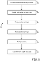
- FIG. 5 is a flow diagram of method 86 for manufacturing the marked consumable materials of the present invention.
- Method 58 includes steps 88-98, and initially involves providing a consumable material precursor, which is the consumable material in an unmarked state (step 88).
- the precursor may be provided as a prefabricated filament in a solid state (e.g., retained on a supply source).
- the precursor may be provided by extruding the modeling or support material to form the precursor.
- suitable techniques for forming the precursor for filament 44 include those disclosed in Comb. et al., U.S. Patent Nos. 6,866,807 and 7,122,246 .
- suitable techniques for forming the precursor for filament 58 include those disclosed in Batchelder et al., U.S. Patent Application Nos. 12/612,333 .
- suitable techniques for forming the precursor for slug 74 include those disclosed in Batchelder et al., U.S. Patent No. 5,764,521 .
- Additional examples of suitable techniques for forming the precursor with topographical surface patterns configured to engage with a filament drive mechanism of system 10 include those disclosed in Batchelder et al., U.S. Patent Application No. 12/612,342 .
- the information to be written to the precursor as encoded markings may also be provided (step 90).
- the information may be retained in one or more computer systems prior to being written to the precursor.
- this information may be obtained by measuring the precursor and storing the measurements in one or more computer systems prior to being written to the precursor as encoded markings. For example, after the precursor of filament 44 is extruded and solidified, the diameters of successive portions of filament 44 may be measured and stored for subsequent writing as at least a portion of encoded markings 50.
- the encoded markings may then be formed at the exterior surface while the precursor is at least partially solidified (step 92). In one embodiment, the encoded markings are formed at the exterior surface while the precursor is fully solidified.
- the pattern of the encoded markings may be based on the information being written, the encoding scheme used, and the device used to mark the precursor. A variety of encoding schemes may be used, where the encoding scheme desirably allows the encoded markings to be written to the precursor without substantially reducing line speeds.
- suitable average line speeds for manufacturing the marked consumable materials include line speeds up to about 20 meters/second (about 750 inches/second), with particularly suitable average line speeds ranging from about 1.3 meters/second (about 50 inches/second) to about 5 meters/second (about 200 inches/second). Additionally, the encoding scheme also desirably allows the encoded markings to be read by sensor assembly 24 or 26 in system 10 without substantially affecting the drive rate of the marked consumable material to extrusion head 18.
- encoded markings 50, 68, and 84 may be formed as trench-based markings in the precursor.
- the trenches may be formed within the exterior surface of the precursor using a variety of techniques, such as laser ablation, physical imprinting, chemical etching (e.g., with masking), and combinations thereof. Due to the small dimensions and materials of the precursor, the particular technique used to form the trenches of the encoded markings is desirably selected to reduce the risk of significantly damaging or cracking the precursor while forming the trenches.
- the edges of the trench marks are suitable regions for scattering light in a darkfield illumination, which may allow an optical sensor assembly to read the encoded markings based on the patterns of the scattered light.
- a suitable laser ablation technique for forming the encoded markings as trenches in the exterior surface of the precursor may be performed with an ultraviolet laser, such as an excimer laser.
- An excimer laser may remove material from the exterior surface of the precursor without significant damage or cracking to the underlying material of the precursor.
- excimer light may be strongly absorbed such that the surface material may be converted to vapor, leaving a trench without micro-cracks or residual ash.
- This embodiment is also beneficial for forming the encoded markings in a continuous manner, in which successive portions of the precursor may be exposed to the excimer laser.
- the encoded markings may be formed with a variety of different processes.
- the encoded markings may be formed with one or more coating processes, which may form the encoded markings on the exterior surface of the precursor as coatings that may be optically detected.
- the coatings may be formed with a jetting, deposition, or evaporation process, where the coating is desirably formed with a material that is not readily visible to the naked eye but may be detected using a non-visible wavelength (e.g., ultraviolet-activated materials).
- the sensor assembly e.g., sensor assemblies 24 and 26
- the encoded markings may be formed by one or more mechanical impression processes, such as by mechanically impressing the pattern into the surface, such as with an agile stylus, rotating die, a recycling belt, and the like.
- the exterior surface may also be machined, skived, ground, polished, and the like.
- the encoded markings may be produced by one or more surface property modification processes, such as by modifying the surface properties of the precursor material.
- the degree of cross linking of the precursor material may be locally modified by ultraviolet light to varying the index of refraction.
- the encoded markings may be generated as lines (e.g., parallel lines) of cross-linked precursor material having different indices of refraction from the remaining surface of the consumable material.
- this embodiment is particularly suitable for use as diffraction gratings with a sensor assembly configured to read information based on far-field diffraction patterns generated from the diffraction gratings. Ion implantation can similarly modify the local complex index.
- the recently formed encoded markings may optionally be read with a sensor assembly to ensure that the information in the encoded markings is accurate (step 94). If the information is determined to be accurate, the marked consumable material may optionally undergo one or more post-processing operations (step 96), and then may be loaded into or onto a supply source (e.g., supply sources 20 and 22) for subsequent use in an additive manufacturing system (e.g., system 10) (step 98). In alternative embodiments, steps 94, 96, and 98 may be performed in different orders and/or one or both of steps 94 and 96 may be omitted.
- a supply source e.g., supply sources 20 and 22
- an additive manufacturing system e.g., system 10
- FIG. 6 is a schematic illustration of marking system 100, which is an example of a suitable laser marking system for forming encoded markings in a consumable material precursor, pursuant to step 92 of method 86 (shown in FIG. 5 ).
- marking system 100 is made with reference to filament 44 (shown in FIG. 2 ) with the understanding that marking system 100 may also be modified for forming encoded markings for a variety of marked consumable materials of the present disclosure (e.g., filament 58 shown in FIG. 3 , and slug 74 shown in FIG. 4 ).
- marking system 100 is a laser ablation system (e.g., an excimer laser ablation system) that includes laser source 102, encoder mask 104, beam splitter 106, reflectors 108, and slot apertures 110.
- Laser source 102 is a laser emission source (e.g., an excimer laser source) for emitting laser beam 112 toward dielectric mask 104.
- laser source 102 is configured to emit laser beam 112 having an ultraviolet-radiation wavelength.
- the wavelength for laser beam 112 ranges from about 100 nanometers to about 400 nanometers.
- the wavelength for laser beam 112 ranges from about 150 nanometers to about 300 nanometers.
- Laser source 102 also desirably emits laser beam 112 with an energy level that is sufficient to form the trenches of encoded markings 50 in the material of the precursor for filament 44, while also desirably being low enough to reduce the risk of significantly damaging or cracking the precursor while forming the trenches.
- suitable energy levels per pulse of laser beam 112 based on a pulse length of about 8 nanoseconds, range from about 4 millijoules to about 20 millijoules, with particularly suitable energy levels ranging from about 8 millijoules to about 15 millijoules.
- Laser source 102 also desirably emits pulses of laser beam 112 with sufficient frequencies to form trenches of encoded markings 50 along successive portions of the precursor of filament 44 while maintaining a suitable line speed for filament 44.
- suitable pulse frequencies for laser beam 112 range from about 500 hertz to about 1,500 hertz.
- Encoder mask 104 is a mask configured to selectively form encoded marks 50 in filament 44 with laser beam 112 based on an encoding scheme.
- suitable encoder masks for encoder mask 104 include fixed and rotary-disk dielectric masks, such as chrome-on-fluoride masks (e.g., glass and quartz-based masks), which may contain coded patterns.
- a rotary disk mask may contain radially coded patterns, where the timing of the pulse of laser beam 112 may select which encoded pattern is illuminated for imprinting onto filament 44.
- Beam splitter 106 is configured to split laser beam 112 into separate laser beams (referred to as laser beams 112a, 112b, and 112c) for forming encoded patterns 50a, 50b, and 50c in filament 44.
- Reflectors 108 are reflective surfaces (e.g., dielectric mirrors) configured to reflect laser beams 112a and 112c back toward filament 44.
- Slot apertures 110 are spaced around filament 44 and are configured to limit the radial dimensions of encoded patterns 50a, 50b, and 50c.
- the precursor of filament 44 may be fed through slot apertures 110, as shown.
- the information to be written to the precursor may then be encoded by a computer system (not shown) in signal communication with system 100.
- the computer system may direct laser source 102 pulse laser beam 112 toward encoder mask 104.
- the encoded pattern in encoder mask 104 may vary the patterns of laser beam 112 that pass through encoder mask 104 to beam splitter 106.
- Beam splitter 106 splits the portion of laser beam 112 that passed through encoder mask 104 into laser beams 112a, 112b, and 112c.
- Laser beams 112a, 112b, and 112c may then be directed to exterior surface 48 of the precursor of filament 44 to desirably form trenches in the precursor based on the laser beam pattern.
- an energy pulse of about 12 millijoules may form a trench by removing about 1.2 square millimeters (about 1,900 square mils) of a polymer (e.g., ABS) to depth of about 2.5 micrometers (about 0.1 mils).
- a polymer e.g., ABS
- laser beam 112 is used to form trenches that are about 0.2 millimeters (about 8 mils) wide (e.g., width 56) and about 2.5 millimeters (about 100 mils) long (e.g., length 54) with a pulse frequency of about 1,000 hertz
- encoded markings 50 may be formed in the precursor at a line speed greater than about 2.5 meters/second (about 100 inches/second).
- system 100 may be used in a continuous process with the extrusion and formation of the precursor of filament 44.
- the marking process may continue as successive portions of the precursor pass through system 100, thereby forming successive trenches of encoded markings 50 along length 46.
- the resulting filament 44 may then subjected to one or more additional steps of method 86 (e.g., steps 94, 96, and 98), as discussed above.
- marking system 100 may be configured to form cross-linked markings in the surface of filament 44.
- the beams of ultraviolet light may cross-link the precursor material of filament 44 to vary the index of refraction at the locations of the encoded markings. This is particularly suitable in which the encoded markings function as diffraction gratings.
- the marked consumable materials of the present disclosure allow information to be recorded in the consumable materials themselves.
- the encoded markings may contain a variety of information relating to the marked consumable materials and/or to the operations of the additive manufacturing systems (e.g., system 10).
- the sensor assemblies e.g., sensor assemblies 24 and 26
- the additive manufacturing systems are configured to read the encoded markings from successive portions of the marked consumable materials as the marked consumable materials are fed to the additive manufacturing systems. This allows the additive manufacturing systems to use the information in the encoded markings for a variety of different purposes, such as for building 3D models and/or support structures.
- sensor assemblies 24 and 26 may be retained partially or fully within supply sources 20 and 22 (shown in FIG. 1 ), respectively.
- sensor assembly 24 may include a first subassembly retained within system 10 at bay 20a, and a second subassembly retained within supply source 20.
- the first and second subassemblies may engage with each other when supply source 20 is loaded to bay 20a of system 10.
- Sensor assembly 26 may also include the same arrangement for bay 22a and supply source 22.
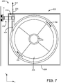
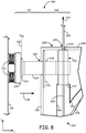
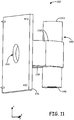
- FIGS. 7-12 illustrate sensor assembly 200 in use with spooled container 202, where sensor assembly 200 is an example of a suitable optical sensor assembly for use in system 10 (e.g., as sensor assembly 24 and/or sensor assembly 26, shown in FIG. 1 ).
- spooled container 202 is a supply source containing filament 204, where filament 204 is a marked filament.
- suitable marked filaments for filament 204 include those discussed above (e.g., filaments 44 and 58).
- suitable sources for spooled container 202 include those discussed above for supply sources 20 and 22 (shown in FIG. 1 ), such as those disclosed in Swanson et al., U.S. Patent No. 6,923,634 ; Comb et al., U.S. Patent No. 7,122,246 ; Taatjes et al, U.S. Patent Application Publication Nos. 2010/0096485 and 2010/0096489 ; and Swanson, U.S. Patent Application No. 12/811,411 and International Publication No. WO2009/088995 .
- filament 204 may be wound around spool 206, which correspondingly may be retained in container housing 208.
- This arrangement allows filament 204 to be unwound from spool 206 while spool 206 rotates around hub 210 within container housing 208, as represented by arrows 212. Filament 204 may then pass through sensor assembly 200 and exit spooled container 202 to a pathway of system 10 (e.g., pathways 36 and 40), as represented by arrow 214.
- a pathway of system 10 e.g., pathways 36 and 40
- Sensor assembly 200 includes subassemblies 216 and 218, which, in the shown embodiment, are separate components that may engage with each other during a build operation.
- Subassembly 216 is retained within system 10, outside of spooled container 202, and contains the sensor electronics (not shown in FIG. 7 ) for reading the encoded markings of filament 204.
- Subassembly 218 is retained at least partially within container housing 208 of spooled container 202, and is the portion that filament 204 passes through prior to exiting spooled container 202. In the shown embodiment, subassembly 218 is fully retained within container housing 208.
- subassembly 216 may engage with subassembly 218 to read encoded markings of filament 204 as successive portions of filament 204 pass through subassembly 218.
- subassembly 216 includes base block 220, circuit board 222, and waveguides 224.
- Base block 220 is a structural mount for retaining circuit board 222. In alterative embodiments, base block 220 may be omitted and circuit board 222 may be directly mounted within system 10.
- Circuit board 222 is a control circuit for subassembly 216 and is configured to optically read the encoded markings of filament 204 as filament 204 passes through subassembly 218 within spooled container 202.
- Circuit board 222 also desirably communicates with controller 32 over a communication line (e.g., communication line 226), as discussed above for communication lines 38 and 42 (shown in FIG. 1 ).
- Waveguides 224 are a pair of waveguides (a single waveguide 224 is shown in FIG. 8 ), which may be fabricated as an integral unit from a transparent or translucent plastic or glass material. Waveguides 224 are configured to route light from one or more light sources (not shown in FIG. 8 ) mounted on circuit board 222 to subassembly 218, as discussed below. Waveguides 224 are also configured to extend into an opening within container housing 208 (referred to as opening 228) to engage subassembly 218.
- subassembly 216 is biased in the direction of arrow 230 toward subassembly 218 by biasing members 232.
- Biasing members 232 are one or more devices configured to bias subassembly 216 toward subassembly 218 when spooled container 202 is loaded to system 10.
- biasing members 232 are loaded springs located between base block 220 and the sidewall of the bay in which supply source 202 is loaded (referred to as sidewall 234).
- subassembly 216 may be mounted and biased from any suitable location within system 10.
- System 10 may also include one or more latching mechanisms (not shown) for retaining subassembly 216 in a retracted state against sidewall 234.
- subassembly 216 may remain in the retracted state while spooled container 202 is being loaded or unloaded from the bay of system 10.
- the latching mechanism may be released, thereby allowing subassembly 216 to engage subassembly 218.
- Subassembly 218 includes window 236, waveguides 238, and filament guide 240, which may be fabricated as an integral unit from a transparent or translucent plastic or glass material.
- Window 236 may be secured to container housing 208 at opening 228, which allows waveguides 224 of subassembly 216 to rest against window 236 at opening 228 due to the bias in the direction of arrow 230.
- Waveguides 238 are a pair of waveguides (a single waveguide 238 is shown in FIG. 8 ) configured to route light from waveguide 224 to filament guide 240.
- filament guide 240 includes a channel for filament 204 to pass through while being fed from spooled container 202 to system 10.
- the biasing of waveguides 224 against window 236 also allows the focal length of sensor assembly 200 to be repeatably fixed. This arrangement allows the light routed through waveguides 224 to also be routed through waveguides 238 to filament guide 240, thereby providing a darkfield illumination for filament 204.
- the trench edges of the encoded markings of filament 204 scatter the light of the darkfield illumination in patterns based on the encoded markings.
- the scattered light may be optically detected at subassembly 216, thereby allowing the information retained in the encoded markings to be read based on the patterns of the scattered light.
- Subassembly 216 may then transmit signals relating to the information to controller 32 over communication line 226.
- subassembly 218 may form a moisture barrier with container housing 208, allowing the interior of container housing 208 to retain a low moisture content.
- filament guide 240 includes inlet end 242 and outlet end 244.
- Inlet end 242 desirably forms a first moisture barrier with the interior walls of container housing 208, which define an interior region in which spool 206 may be retained (referred to as interior walls 246).
- spooled container 202 may include one or more liners in addition to, or as an alternative to interior walls 246.
- suitable liners include those disclosed in Swanson, U.S. Patent Application No. 12/811,411 and International Publication No. WO2009/088995 .
- the liner may partially or fully encase spool 206 and may be secured around inlet end 242 of filament guide 240 to maintain a moisture barrier within container housing 208.
- outlet end 244 desirably forms a second moisture barrier with the exterior walls of container housing 208 (referred to as exterior walls 248) at the exit orifice of container housing 208 (referred to as exit orifice 250).
- the pathway of system 10 to extrusion head 18 e.g., pathways 36 and 40, not shown in FIG. 8 ) may also form a moisture barrier at exit orifice 250 to maintain the low moisture environment between spooled container 202 and extrusion head 18.
- the moisture barriers formed between container housing 208 and filament guide 240 of subassembly 218 allow the interior region of spooled container 202 to be maintained at a low humidity level to reduce the absorption of water into filament 204.
- Spooled container 202 may also include desiccant packs (not shown) within the interior region to maintain a dry environment. These implementations may allow filament 204 to maintain a low moisture content (e.g., less than about 700 parts-per-million by weight) during storage and use.
- FIG. 9 is a bottom perspective view of sensor assembly 200, where spooled container 202 and base block 220 are omitted for ease of discussion.
- waveguides 224 are a first pair of waveguides that are integrally connected at bridge 252.
- subassembly 216 also includes optical sensor 254, which may be secured to circuit board 222, as shown.
- Optical sensor 254 is a sensor configured to detect light scattered from the encoded markings of filament 204. Examples of suitable units for optical sensor 254 include one or more imaging devices, such as a complementary metal-oxide-semiconductor (CMOS) camera.
- CMOS complementary metal-oxide-semiconductor
- Optical sensor 254 desirably exhibits imaging capabilities to detect the scattered light patterns from the encoded markings of filament 204. Suitable imaging capabilities may vary depending on the light intensity of the darkfield illumination, the encoding scheme used, and the dimensions of the encoded markings. For example, an marking pattern of multiple marks having a length of about 2.5 millimeters may be imaged with a 2:1 magnification onto a 640x480 pixel array. Examples of suitable commercially available CMOS cameras and corresponding image processors for circuit board 222 and optical sensor 254 include those from Aptina Imaging Corporation, Grand Cayman, KY; and those from Toshiba Corporation, Minato, Tokyo, Japan.
- subassembly 216 also includes a plurality of light sources (not shown in FIG. 9 ) mounted on circuit board 222 at indentations in waveguides 224 adjacent to circuit board 222 (referred to as indentations 256).
- the light sources may be mounted at any suitable location within system 10.
- Waveguides 238 are a second pair of waveguides that are integrally connected at bridge 258, where bridge 258 includes opening 260. Opening 260 provides an access location for the light reflected from filament 204 (including the light scattered from the encoded markings of filament 204) to transmit through to reach optical sensor 254. As discussed below, one or more lenses may also be located between optical sensor 254 and opening 260 for increasing or otherwise modifying the focus and magnification of the transmitted light.
- waveguides 224 substantially align with waveguides 238 along the x-axis. This allows the light routed through waveguides 224 to pass through window 236 to waveguides 238. Waveguides 238 also route the received light, and the opposing end of waveguides 238 converge toward each other around filament guide 240. This causes the routed light to reflect at least once prior reaching filament 204 to provide a darkfield illumination, as discussed below.
- FIG. 10 is an exploded perspective view of subassembly 216.
- bridge 252 of waveguides 224 includes opening 262, which desirably aligns with opening 260 (shown in FIG. 9 ) when subassembly 216 engages subassembly 218.
- openings 260 and 262 may retain one or more lenses for increasing or otherwise modifying the focus and magnification of the transmitted light.
- light sources 264 are mounted to circuit board 222 and desirably align with indentations 256 of waveguides 224.
- Light sources 264 may be any suitable type of light source to provide a darkfield illumination for filament 204, such as light emitting diodes (LEDs). Additionally, while shown as two pairs of LEDs, subassembly 216 may include a variety of different numbers of light sources for providing a darkfield illumination for filament 204. In one embodiment, light sources 264 may include multiple color LEDs, such as red, green, and blue LEDs, which may be selectively used to illuminate filament 204.
- FIG. 11 is a perspective view of subassembly 218.
- window 236 of subassembly 218 also includes opening 266, which is aligned with opening 260 (shown in FIG. 9 ), and desirably aligns with opening 262 (shown in FIG. 10 ) when subassembly 216 engages subassembly 218.
- Openings 266 may also retain one or more lenses for increasing or otherwise modifying the focus and magnification of the transmitted light.
- FIG. 12 is a bottom view of sensor assembly 200, where subassembly 216 is engaged with subassembly 218.
- filament 204 may be fed through the channel of filament guide 240 (referred to as channel 268).
- Channel 268 desirably has dimensions that allow filament 204 to pass through filament guide 240 without undue friction while also desirably confining filament 204 to the object plane of optical sensor 254 such that the grazing angle input light scatters from the encoded markings of filament 204.
- suitable average inner diameters for channel 268 range from about 1.0 millimeter (about 0.04 inches) to about 3.8 millimeters (about 0.15 inches), and with particularly suitable average diameters ranging from about 1.3 millimeters (about 0.05 inches) to about 2.5 millimeters (about 0.1 inches).
- channel 268 may include a cross section that substantially matches the geometry of the marked non-cylindrical filament.
- the marked non-cylindrical filament has a rectangular cross section (e.g., filament 58)
- channel 268 desirably has a rectangular cross section with a width-to-thickness aspect ratio that substantially matches the aspect ratio of the filament.
- suitable average widths for channel 268 range from about 1.3 millimeters (about 0.05 inches) to about 12.7 millimeters (about 0.50 inches), with particularly suitable average widths ranging from about 3.8 millimeters (about 0.15 inches) to about 10.2 millimeters (about 0.40 inches).
- Suitable average thicknesses for channel 268 range from about 0.25 millimeters (about 0.01 inches) to about 2.5 millimeters (about 0.1 inches), with particularly suitable average thicknesses ranging from about 0.51 millimeters (about 0.02 inches) to about 1.8 millimeters (about 0.07 inches).
- the encoding scheme used desirably allows the encoded markings to be read by sensor assembly 200 without substantially affecting the drive rate of filament 204 to extrusion head 18.
- the drive rate of filament 204 to extrusion head 18 may vary depending the extrusion parameters in extrusion head 18 and the dimensions of filament 204. Examples of suitable drive rates range from about 2.5 millimeters/second (about 100 mils/second) to about 7.6 millimeters/second (about 300 mils/second).
- the converging orientations of waveguides 238 desirably cause the routed light to reflect at least once prior reaching filament 204 to provide a darkfield illumination.
- the light desirably reflects at least once before grazing the exterior surface of filament 204 within filament guide 240.
- a portion of the reflected and scattered light may then transmit through openings 266, 260, and 262 (and through any lenses retained therein) toward optical sensor 254.
- Optical sensor 254 may image the received light, which, which may then be processed by circuit board 222 and/or controller 32 (via communication line 226) to decode the information from the image patterns based on the encoding scheme used. Controller 32 may then use the received information to assist in the operation to build 3D model 28 and/or support structure 30, as discussed above.
- FIG. 13 illustrates sensor assembly 300 in use with spooled container 302, where sensor assembly 300 is an example of a suitable sensor assembly for use in system 10 (e.g., as sensor assembly 24 and/or sensor assembly 26, shown in FIG. 1 ).
- spooled container 302 is a supply source containing filament 304, where filament 304 is a marked filament. Examples of suitable marked filaments for filament 304 include those discussed above (e.g., filaments 44 and 58).
- spooled container is mounted in a bay of system 10 (e.g., bay 20a), which includes front wall 305.
- suitable sources for spooled container 302 include those discussed above for supply sources 20 and 22 (shown in FIG. 1 ), such as those disclosed in Swanson et al., U.S. Patent No. 6,923,634 ; Comb et al., U.S. Patent No. 7,122,246 ; Taatjes et al, U.S. Patent Application Publication Nos. 2010/0096485 and 2010/0096489 ; and Swanson, U.S. Patent Application No. 12/811,411 and International Publication No. WO2009/088995 .
- filament 304 may be wound around spool 306, which correspondingly may be retained in container housing 308.
- This arrangement allows filament 304 to be unwound from spool 306 while spool 306 rotates around hub 310 within container housing 308, as represented by arrows 312. Filament 304 may then pass through sensor assembly 300 and exit spooled container 302 to a pathway of system 10 (e.g., pathways 36 and 40), as represented by arrow 314.
- a pathway of system 10 e.g., pathways 36 and 40
- spooled container 302 also includes liner 316, which includes one or more films configured to provide a moisture barrier within container housing 308.
- suitable liners for liner 316 include those disclosed in Swanson, U.S. Patent Application No. 12/811,411 and International Publication No. WO2009/088995 .
- sensor assembly 300 is fully retained within housing 308, and within liner 316. While sensor assembly 300 is illustrated in FIG. 13 as being located in a particular location within housing 308 and liner 316 (i.e., in an upper-left corner in the view shown in FIG. 13 ), sensor assembly 300 may alternatively be disposed in other locations within housing 308 and liner 316 such that filament 304 may pass through (or adjacent to) sensor assembly 300 prior to exiting liner 316 and/or housing 308.
- Sensor assembly 300 may receive electrical power from and/or communicate with system 10 via signal lines 318 or other suitable power and/or signal communication techniques.
- signal lines 318 may be arranged in an engagement manner as disclosed in one or more of Swanson et al., U.S. Patent No. 6,923,634 ; Comb et al., U.S. Patent No. 7,122,246 ; Taatjes et al, U.S. Patent Application Publication Nos. 2010/0096485 and 2010/0096489 ; and Swanson, U.S. Patent Application No. 12/811,411 and International Publication No. WO2009/088995 .
- a portion of signal lines 318 desirably extends through liner 316 in a sealable manner that maintains the moisture barrier.
- filament 304 passes through sensor assembly 300 prior to exiting liner 316 and housing 308.
- sensor assembly 300 may read the encoded markings of filament 304 and transmit signals relating to the read markings to system 10.
- Sensor assembly 300 may read the encoded markings of filament 304 using a variety of different techniques, which may vary depending on the particular marking techniques used to form the encoded markings along filament 304.
- FIG. 14 is a schematic illustration of a suitable embodiment of sensor assembly 300, which is configured to read the encoded markings based on far-field diffraction patterns.
- filament 304 includes encoded markings 320 formed on surface 322, where the pattern of encoded markings 320 function as diffraction gratings having different indices of refractions from the remaining portions of surface 322.
- Encoded markings 320 may be formed on or in surface 322 using one or more of the techniques discussed above.
- the degree of cross linking of the precursor material may be locally modified by ultraviolet light to varying the index of refraction at the locations of encoded markings 320.
- sensor assembly 300 includes light emitter 324 and optical detectors 326.
- sensor assembly 300 may include multiple light emitters and/or a different number of optical detectors 326.
- optical detectors 326 are desirably positioned such that diffracted beams of light from encoded markings 320 are directed to optical detectors 326. The directions of the diffracted beams of light from encoded markings 320 may correspondingly be predetermined by the encoding pattern(s) of encoded markings 320.
- Encoded markings 320 are configured to diffract all or a portion of the incident light beam 328 into separate diffracted beams 330. Diffracted beams 330 may be separately detected by optical detectors 326, thereby generating electrical signals indicative of the information encoded in encoded markings 320.
- the information may then be transmitted to controller 32 of system 10 (shown in FIG. 1 ) over electrical connection lines 318 (shown in FIG. 13 ) and communication line 36 or 40 (shown in FIG. 1 ). Controller 32 may then use the received information to assist in the operation to build 3D model 28 and/or support structure 30, as discussed above.
- the marked consumable materials of the present disclosure allow information to be recorded in the consumable materials themselves.
- the encoded markings contain a variety of information relating to the marked consumable materials and/or to the operations of the direct digital or additive manufacturing systems (e.g., system 10).
- the sensor assemblies e.g., sensor assemblies 24, 26, 200, and 300
- the additive manufacturing systems are configured to use the information in the encoded markings for a variety of different purposes, such as for building 3D models and/or support structures.
Description
- The present disclosure relates to direct digital or additive manufacturing systems for building three-dimensional (3D) models. In particular, the present disclosure relates to consumable materials, such as modeling and support materials, for use in additive manufacturing systems, such as extrusion-based additive manufacturing systems, and to sensors for use with the consumable materials.
- An extrusion-based, direct digital or additive manufacturing system (e.g., fused deposition modeling systems developed by Stratasys, Inc., Eden Prairie, MN) is used to build a 3D model from a digital representation of the 3D model in a layer-by-layer manner by extruding a flowable consumable modeling material. The modeling material is extruded through an extrusion tip carried by an extrusion head, and is deposited as a sequence of roads on a substrate in an x-y plane. The extruded modeling material fuses to previously deposited modeling material, and solidifies upon a drop in temperature. The position of the extrusion head relative to the substrate is then incremented along a z-axis (perpendicular to the x-y plane), and the process is then repeated to form a 3D model resembling the digital representation.
- Movement of the extrusion head with respect to the substrate is performed under computer control, in accordance with build data that represents the 3D model. The build data is obtained by initially slicing the digital representation of the 3D model into multiple horizontally sliced layers. Then, for each sliced layer, the host computer generates a build path for depositing roads of modeling material to form the 3D model.
- In fabricating 3D models by depositing layers of a modeling material, supporting layers or structures are typically built underneath overhanging portions or in cavities of objects under construction, which are not supported by the modeling material itself. A support structure may be built utilizing the same deposition techniques by which the modeling material is deposited. The host computer generates additional geometry acting as a support structure for the overhanging or free-space segments of the 3D model being formed. Consumable support material is then deposited from a second nozzle pursuant to the generated geometry during the build process. The support material adheres to the modeling material during fabrication, and is removable from the completed 3D model when the build process is complete.
-
GB 2 282 345 A - The present invention is directed to an encoded consumable filament according to
claim 1 and a method for building a three-dimensional model according to claim 8. - A marked consumable filament and an encoded consumable filament refer to the same feature.
-
-
FIG. 1 is a front view of an extrusion-based additive manufacturing system for building 3D models and support structures from marked consumable materials having encoded markings. -
FIG. 1A is a front view of an alternative extrusion-based additive manufacturing system for building 3D models and support structures from marked consumable materials having encoded markings, which includes sensor assemblies retained along consumable material pathways of the system. -
FIG. 2 is a perspective view of a segment of a marked cylindrical filament, which is an example of a marked consumable material for use in the extrusion-based additive manufacturing systems. -
FIG. 3 is a perspective view of a segment of a marked non-cylindrical filament, which is an additional example of a marked consumable material for use in the extrusion-based additive manufacturing systems. -
FIG. 4 is a perspective view of a marked slug or wafer, which is an additional example of a marked consumable material for use in the extrusion-based additive manufacturing systems. -
FIG. 5 is a flow diagram of a method for manufacturing marked consumable materials. -
FIG. 6 is a schematic illustration of a laser marking system configured to form encoded markings in consumable materials. -
FIG. 7 is a schematic illustration of a sensor assembly of one embodiment of the present disclosure in use with a spooled container, where the sensor assembly contains a first subassembly located within an extrusion-based additive manufacturing system and a second subassembly located within a spooled container. -
FIG. 8 is an expanded view of the sensor assembly shown inFIG. 7 . -
FIG. 9 is a bottom perspective view of the sensor assembly. -
FIG. 10 is an exploded perspective view of the first subassembly of the sensor assembly. -
FIG. 11 is a perspective view of the second subassembly of the sensor assembly. -
FIG. 12 is a bottom view of the sensor assembly, illustrating an engagement and operation of the first and second subassemblies. -
FIG. 13 is a schematic illustration of a sensor assembly of a second embodiment of the present disclosure in use with a spooled container. -
FIG. 14 is an expanded schematic illustration of an example of the second embodied sensor assembly in use with a marked consumable material, where the shown sensor assembly is configured to detect far-field diffraction patterns. - The present disclosure is directed to marked consumable materials for use in additive manufacturing systems (also referred to as direct digital manufacturing systems), such as extrusion-based digital manufacturing systems. The marked consumable materials include encoded markings that may contain a variety of information, such as information relating to properties of the marked consumable materials (e.g., physical and compositional properties) and information relating to parameters for operating the additive manufacturing systems (e.g., extrusion parameters).
- The present disclosure is also directed sensor assemblies configured to read the encoded markings from successive portions of the marked consumable materials as the marked consumable materials are fed to the additive manufacturing systems. As discussed below, the sensor assemblies may transmit the information read from the encoded markings to one or more control components of the additive manufacturing systems. This allows the additive manufacturing systems to use the information in the encoded markings for a variety of different purposes, such as for building 3D models and/or support structures.
-
FIG. 1 is a front view ofsystem 10, which is an additive or direct digital manufacturing system, such as an extrusion-based additive manufacturing system. Suitable extrusion-based additive manufacturing systems forsystem 10 include fused deposition modeling systems developed by Stratasys, Inc., Eden Prairie, MN. As shown,system 10 includesbuild chamber 12,platen 14,gantry 16,extrusion head 18,supply sources sensor assemblies FIG. 1 ) provided insupply sources -
Build chamber 12 is an enclosed environment that containsplaten 14,gantry 16, andextrusion head 18 for building a 3D model (referred to as 3D model 28) and a corresponding support structure (referred to as support structure 30).Build chamber 12 is desirably heated to reduce the rate at which the modeling and support materials solidify after being extruded and deposited. -
Platen 14 is a platform on which3D model 28 andsupport structure 30 are built, and moves along a vertical z-axis based on signals provided from a computer-operated controller (referred to as controller 32). As shown,controller 32 may communicate withbuild chamber 12,platen 14,gantry 16, andextrusion head 18 overcommunication line 34. While illustrated as a single signal line,communication line 34 may include one or more signal lines for allowingcontroller 32 to communicate with various components ofsystem 10, such asbuild chamber 12,platen 14,gantry 16, andextrusion head 18. - Gantry 16 is a guide rail system configured to move
extrusion head 18 in a horizontal x-y plane withinbuild chamber 12 based on signals provided from controller 32 (via communication line 34). The horizontal x-y plane is a plane defined by an x-axis and a y-axis (not shown inFIG. 1 ), where the x-axis, the y-axis, and the z-axis are orthogonal to each other. In an alternative embodiment,platen 14 may be configured to move in the horizontal x-y plane withinbuild chamber 12, andextrusion head 18 may be configured to move along the z-axis. Other similar arrangements may also be used such that one or both ofplaten 14 andextrusion head 18 are moveable relative to each other. -
Extrusion head 18 is supported bygantry 16 for building3D model 28 andsupport structure 30 onplaten 14 in a layer-by-layer manner, based on signals provided fromcontroller 32.Extrusion head 18 includes a pair of liquefiers (not shown inFIG. 1 ) configured to receive and melt successive portions of the marked consumable materials. Examples of suitable extrusion heads forextrusion head 18 include those disclosed inLaBossiere, et al., U.S. Patent Application Publication Nos. 2007/0003656 and2007/00228590 Leavitt, U.S. Patent Application Publication No. 2009/0035405 ; andBatchelder et al., U.S. Patent Application Nos. 12/612,329 ;12/612,333 12/612,342 system 10 may include one or more two-stage pump assemblies, such as those disclosed inBatchelder et al., U.S. Patent No. 5,764,521 ; andSkubic et al., U.S. Patent Application Publication No. 2008/0213419 . Furthermore,system 10 may include a plurality ofextrusion heads 18 for depositing modeling and/or support materials. -
Supply sources bays system 10. In the shown embodiment,supply source 20 retains a supply of a marked modeling material andsupply source 22 retains a supply of a marked support material.System 10 may also include additional drive mechanisms (not shown) configured to assist in feeding the marked consumable materials fromsupply sources extrusion head 18. The marked consumable materials are provided tosystem 10 as filaments having marked exterior surfaces (not shown inFIG. 1 ), such as marked cylindrical filaments and/or marked non-cylindrical filaments, as discussed below. In these embodiments, suitable assemblies (e.g., spooled containers) forsupply sources Swanson et al., U.S. Patent No. 6,923,634 ;Comb et al., U.S. Patent No. 7,122,246 ;Taatjes et al, U.S. Patent Application Publication Nos. 2010/0096485 and2010/0096489 ; andSwanson, U.S. Patent Application No. 12/811,411 and International Publication No.WO2009/088995 . -
Sensor assemblies extrusion head 18.Sensor assembly 24 may be retained at any suitable location between (or within)supply source 20 andextrusion head 18. Similarly,sensor assembly 26 may be retained at any suitable location between (or within)supply source 22 andextrusion head 18. In the shown example,sensor assemblies supply sources - In alternative embodiments, as disclosed in
U.S. Patent Application No. 12/622,042 and shown inFIG. 1A ,sensor assemblies system 10 adjacent to supplysources sensor assemblies gantry 16 withextrusion head 18, thereby movingsensor assemblies extrusion head 18. - As shown in
FIG. 1 , the marked modeling material may be provided toextrusion head 18 fromsupply source 20 throughpathway 36, wherepathway 36 may include a guide tube (not shown) for guiding the marked modeling material toextrusion head 18. In the shown embodiment,pathway 36 is downstream fromsensor assembly 24, thereby allowingsensor assembly 24 to read the encoded information from the marked modeling material prior to passing throughpathway 36. As further shown,sensor assembly 24 may communicate withcontroller 32 and/or any other control component of system 10 (e.g., a host computer system forsystem 10, not shown) overcommunication line 38. While illustrated as a single signal line,communication line 38 may include one or more signal lines for allowingsensor assembly 24 to communicate with one or more control components of system 10 (e.g., controller 32). - Similarly, the marked support material may be provided to
extrusion head 18 fromsupply source 22 throughpathway 40, wherepathway 40 may also include a guide tube (not shown) for guiding the marked support material toextrusion head 18. In the shown embodiment,pathway 40 is downstream fromsensor assembly 26, thereby allowingsensor assembly 26 to read the encoded information from the marked support material prior to passing throughpathway 40. As further shown,sensor assembly 26 may communicate withcontroller 32 and/or any other control component of system 10 (e.g., the host computer system for system 10) overcommunication line 42. While illustrated as a single signal line,communication line 42 may include one or more signal lines for allowingsensor assembly 26 to communicate with one or more control components of system 10 (e.g., controller 32). - During a build operation, the marked consumable materials are fed to
extrusion head 18 throughpathways Sensor assemblies supply sources pathways controller 32 overcommunication lines controller 32 to use the received information to assist in building3D model 28 and/orsupport structure 30. Thecontroller 32 modifies the extrusion parameters transmitted toextrusion head 18, allowing the thermal properties ofextrusion head 18 to be adjusted based on the received information. The thermal properties ofextrusion head 18 are adjusted based on received information relating to the cross sectional areas of successive portions of the consumable materials. - Additionally, the received information may relate to the amount of the marked consumable materials remaining in
supply source system 10 how long the current supply of the marked consumable material will last before the user needs to load a new supply source tosystem 10. This information is particularly suitable for allowing the user to know if the build operation will end during a time period when the user may not necessarily be present to load a new supply source to system 10 (e.g., during overnight and/or weekend periods). - Furthermore, the received information may relate to the marked consumable material itself, such as the material type (e.g., modeling and support materials), material composition, and/or the material color.
Sensor assemblies system 10, thereby reducing the risk of accidentally runningsystem 10 with an incorrect material. For example,sensor assembly 24 may read information from the marked consumable material being fed fromsupply source 20, andcontroller 32 may confirm that the material being fed throughpathway 36 is an intended modeling material, rather than a support material. - Combinations of the read information may also be used to assist in building
3D model 28 and/orsupport structure 30. For example, in embodiments in whichbays supply source 20 of the marked modeling material into eitherbay 20a orbay 22a, and after thecorresponding sensor assembly controller 32 may identify that the material is a modeling material for building3D model 28 and adjust the extrusion parameters and feed rates accordingly. A similar arrangement may be accomplished with the marked support material insupply source 22. This prevents the user from having to load a particular supply source into a particular bay ofsystem 10. - As the marked consumable materials are fed to
extrusion head 18,gantry 16 may moveextrusion head 18 around in the horizontal x-y plane withinbuild chamber 12.Extrusion head 18 thermally melts the successive portions of the received marked modeling material, thereby allowing the molten modeling material to be extruded to build3D model 28. Similarly,extrusion head 18 thermally melts the successive portions of the marked support material, thereby allowing the molten support material to be extruded to buildsupport structure 30. The upstream, unmelted portions of the marked consumable materials may each function as a piston with a viscosity-pump action to extrude the molten material out of the respective liquefiers ofextrusion head 18. - The extruded modeling and support materials are deposited onto
platen 14 to build3D model 28 andsupport structure 30 using a layer-based additive technique.Support structure 30 is desirably deposited to provide vertical support along the z-axis for overhanging regions of the layers of3D model 28. After the build operation is complete, the resulting3D model 28/support structure 30 may be removed frombuild chamber 12, andsupport structure 30 may be removed from3D model 28. As used herein, the term "three-dimensional model" is intended to encompass any object built with an additive manufacturing system, and includes 3D models built from modeling materials (e.g., 3D model 28) as well a support structures built from support materials (e.g., support structure 30). -
FIG. 2 illustrates a segment offilament 44, which is an example of marked consumable material, not part of the claimed invention, for use as a marked modeling material and/or a marked support material with system 10 (shown inFIG. 1 ). As shown inFIG. 2 ,filament 44 is a marked cylindricalfilament having length 46, wherelength 46 is a continuous length that may vary depending on the amount offilament 44 remaining insupply source filament 44 is illustrated inFIG. 2 , it is understood thatlength 46 offilament 44 may extend for a substantial distance (e.g., greater than 25 meters). -
Filament 44 also includesexterior surface 48 extending alonglength 46 and encodedmarkings 50, where encodedmarkings 50 are located atexterior surface 48 along at least a portion oflength 46. In one embodiment, encodedmarkings 50 extend substantially along theentire length 46.Filament 44 also has a surface diameter (referred to as surface diameter 52) at a non-marked location that is desirably configured to allowfilament 44 to mate with a liquefier ofextrusion head 18 without undue friction. Examples of suitable average diameters forsurface diameter 52 range from about 0.8 millimeters (about 0.03 inches) to about 2.5 millimeters (about 0.10 inches), with particularly suitable average diameters ranging from about 1.0 millimeter (about 0.04 inches) to about 2.3 millimeters (about 0.09 inches), and with even more particularly suitable average diameters ranging from about 1.3 millimeters (about 0.05 inches) to about 2.0 millimeters (about 0.08 inches). - In the shown embodiment, encoded
markings 50 are trench-based markings in exterior surface 48 (e.g., via laser ablation). However, as discussed below, encodedmarkings 50 may alternatively be form onfilament 44 using a variety of different marking techniques. For example, encodedmarkings 50 may be formed as coatings overexterior surface 48 via one or more coating processes (e.g., jetting and evaporation processes). Alternatively, encodedmarkings 50 may be formed by cross-linking the surface material offilament 44, such as with ultraviolet light, to vary the index of refraction of the material at encodedmarkings 50. This is particularly suitable in embodiments in which encodedmarkings 50 function as diffraction gratings. - Encoded
markings 50 include encoded information, which may be read bysensor assembly filament 44 pass throughpathway system 10. As discussed above, the read information may then be transmitted tocontroller 32 overcommunication line controller 32 to use the received information to assist in building3D model 28 and/orsupport structure 30. - Encoded
markings 50 may extend in multiple linear paths along length 46 (referred to aspaths markings 50 may also include a third linear path (referred to as path 50c, not shown) such thatpaths sensor assembly paths filament 44 as successive portions offilament 44 pass through the givensensor assembly filament 44 may include fewer or additional paths of encodedmarkings 50 such thatfilament 44 includes at least one path of encoded markings 50 (e.g.,paths paths length 46 in a non-linear manner (e.g., S-curves and spiral arrangements). - Encoded
markings 50 may include a variety of different information, such as information relating tofilament 44 and/orsystem 10. Examples of suitable types of information that may be included in encodedmarkings 50 include local filament cross-sections (e.g., diameters and root-mean-square variations), local and global filament extrusion parameters, length offilament 44 remaining insupply source system 10, and combinations thereof. - In addition, encoded
markings 50 may also include media-based information, such as operating and use instructions, artistic works (e.g., textual, video, and audio information), and the like. In these embodiments,system 10 may include capabilities for playing the encoded media, such as textual and/or graphical information that may be displayed for a user ofsystem 10 to read, and/or audio information that may be played for a user ofsystem 10 to hear. The amount of data per unit length alonglength 46 offilament 44 may vary depending on the particular marking technique used, the encoding scheme used, the dimensions of encodedmarkings 50, the number of encoded markings per unit length alonglength 46, and the like. - The dimensions and geometries of each mark of encoded
markings 50 may vary depending on the encoding scheme and the marking technique used. In the current example in which encodedmarkings 50 are formed as trenches in exterior surface 48 (e.g., via laser ablation), encodedmarkings 50 desirably have small dimensions relative to the overall dimensions offilament 44 to minimize or otherwise reduce their impact on the diameter offilament 44. Additionally, as shown in the current embodiment, the trenches of encodedmarkings 50 have axial lengths (e.g., axial length 54) that vary to provide patterns based on the encoding scheme used. In alternative embodiments one or more of the radial widths of the marks (referred to as widths 56) and/or the depths of the marks may additionally or alternatively be varied to provide patterns based on the encoding scheme used. - Suitable average dimensions for
width 56 range from about 51 micrometers (about 2 mils) to about 510 micrometers (about 20 mils), with particularly suitable average dimensions ranging from about 130 micrometers (about 5 mils) to about 250 micrometers (about 10 mils). Suitable dimensions for the axial lengths along length 46 (e.g., axial length 54) range from about 130 micrometers (about 5 mils) to about 5,100 micrometers (about 200 mils), with particularly suitable axial lengths ranging from about 1,300 micrometers (about 50 mils) to about 3,800 micrometers (about 150 mils). - Furthermore, suitable average depths of each mark of encoded
markings 50 fromexterior surface 48 range from about 1.3 micrometers (about 0.05 mils) to about 51 micrometers (about 2 mils), with particularly suitable average depths ranging from about 13 micrometers (about 0.5 mil) to about 38 micrometers (about 1.5 mils). As discussed below, the edges of the trench marks are suitable regions for scattering light in a darkfield illumination, which may allow an optical sensor assembly to read encodedmarkings 50 based on the patterns of the scattered light. In alternative embodiments, the encoded markings offilament 44 may be two-dimensional markings (e.g., coatings) rather than the three-dimensional geometry of encodedmarkings 50. - In further alternative embodiments, the axial lengths (e.g., axial length 54) and the radial widths (e.g., widths 56) of encoded
markings 50 may be the same or substantially the same. In these embodiments, the patterns of encodedmarkings 50 alonglength 46 offilament 44 may vary to provide the encoding properties. For example, in embodiments in which encodedmarkings 50 function as diffraction gratings, encodedmarkings 50 may be formed as patterns of parallel lines having different indices of refraction from that ofexterior surface 48. The parallel lines of encodedmarkings 50 may be the same or similar in geometry. However, the patterns of the parallel lines and the interstitial areas ofexterior surface 48 may define the encoded pattern infilament 44. -
Filament 44 may be manufactured from a variety of extrudable modeling and support materials for respectively building3D model 28 andsupport structure 30. Suitable modeling materials forfilament 44 include polymeric and metallic materials. In some embodiments, suitable modeling materials include materials having amorphous properties, such as thermoplastic materials, amorphous metallic materials, and combinations thereof. Examples of suitable thermoplastic materials forfilament 44 include acrylonitrile-butadiene-styrene (ABS) copolymers, polycarbonates, polysulfones, polyethersulfones, polyphenylsulfones, polyetherimides, amorphous polyamides, modified variations thereof (e.g., ABS-M30 copolymers), polystyrene, and blends thereof. Examples of suitable amorphous metallic materials include those disclosed inBatchelder, U.S. Patent Application Publication No. 2009/0263582 . - Suitable support materials for
filament 44 include polymeric materials. In some embodiments, suitable support materials include materials having amorphous properties (e.g., thermoplastic materials) and that are desirably removable from the corresponding modeling materials after3D model 28 andsupport structure 30 are built. Examples of suitable support materials forfilament 44 include water-soluble support materials commercially available under the trade designations "SR10", "SR20", and "SR30" Soluble Supports from Stratasys, Inc., Eden Prairie, MN; break-away support materials commercially available under the trade designation "BASS" from Stratasys, Inc., Eden Prairie, MN, and those disclosed inCrump et al., U.S. Patent No. 5,503,785 ;Lombardi et al., U.S. Patent Nos. 6,070,107 and6,228,923 ;Priedeman et al., U.S. Patent No. 6,790,403 ; andHopkins et al., U.S. Patent Application Publication No. 2010/0096072 . - The composition of
filament 44 may also include additional additives, such as plasticizers, rheology modifiers, inert fillers, colorants, stabilizers, and combinations thereof. Examples of suitable additional plasticizers for use in the support material include dialkyl phthalates, cycloalkyl phthalates, benzyl and aryl phthalates, alkoxy phthalates, alkyl/aryl phosphates, polyglycol esters, adipate esters, citrate esters, esters of glycerin, and combinations thereof. Examples of suitable inert fillers include calcium carbonate, magnesium carbonate, glass spheres, graphite, carbon black, carbon fiber, glass fiber, talc, wollastonite, mica, alumina, silica, kaolin, silicon carbide, composite materials (e.g., spherical and filamentary composite materials), and combinations thereof. In embodiments in which the composition includes additional additives, examples of suitable combined concentrations of the additional additives in the composition range from about 1% by weight to about 10% by weight, with particularly suitable concentrations ranging from about 1% by weight to about 5% by weight, based on the entire weight of the composition. -
Filament 44 also desirably exhibits physical properties that allowfilament 44 to be used as a consumable material insystem 10. For example,filament 44 is desirably flexible alonglength 46 to allowfilament 44 to be retained insupply sources 20 and 22 (e.g., wound on spools) and to be fed through system 10 (e.g., throughpathways 36 and 40) without plastically deforming or fracturing. For example, in one embodiment,filament 44 is capable of withstanding elastic strains greater than t/r, where "t" is a cross-sectional thickness offilament 44 in the plane of curvature, and "r" is a bend radius (e.g., a bend radius insupply source pathway 36 or 40). - In one embodiment, the composition of
filament 44 is substantially homogenous alonglength 46. Additionally, the composition offilament 44 desirably exhibits a glass transition temperature that is suitable for use inbuild chamber 12. Examples of suitable glass transition temperatures at atmospheric pressure for the composition offilament 44 include temperatures of about 80°C or greater. In some embodiments, suitable glass transition temperatures include about 100°C or greater. In additional embodiments, suitable glass transition temperatures include about 120°C or greater. -
Filament 44 also desirably exhibits low compressibility such that its axial compression doesn't causefilament 44 to be seized within a liquefier. Examples of suitable Young's modulus values for the polymeric compositions offilament 44 include modulus values of about 0.2 gigapascals (GPa) (about 30,000 pounds-per-square inch (psi)) or greater, where the Young's modulus values are measured pursuant to ASTM D638-08. In some embodiments, suitable Young's modulus range from about 1.0 GPa (about 145,000 psi) to about 5.0 GPa (about 725,000 psi). In additional embodiments, suitable Young's modulus values range from about 1.5 GPa (about 200,000 psi) to about 3.0 GPa (about 440,000 psi). -
FIG. 3 illustrates a segment offilament 58 of the present invention for use as a modeling material and/or a support material with system 10 (shown inFIG. 1 ). As shown inFIG. 3 ,filament 58 is a marked non-cylindricalfilament having length 60, wherelength 60 is a continuous length that may vary depending on the amount offilament 58 remaining insupply source filament 58 is illustrated inFIG. 3 , it is understood thatlength 60 offilament 58 may extend for a substantial distance (e.g., greater than 25 meters). -
Filament 58 also includesexterior surface 62 extending alonglength 60 and havingmajor surfaces 64 and 66, which are the opposing major surfaces offilament 58.Filament 58 further includes encodedmarkings 68 located atmajor surface 64 ofexterior surface 62, along at least a portion oflength 60. In one embodiment, encodedmarkings 68 extend substantially along theentire length 60. - In the shown embodiment, encoded
markings 68 are trench-based markings in exterior surface 62 (e.g., via laser ablation), as discussed above for encodedmarkings 50 of filament 44 (shown inFIG. 2 ). However, as discussed below, encodedmarkings 68 may alternatively be formed onfilament 58 using a variety of different marking techniques (e.g., via one or more coating processes). For example, encodedmarkings 68 may be formed by cross-linking the surface material offilament 58, such as with ultraviolet light, to vary the index of refraction of the material at encodedmarkings 68. This is particularly suitable in embodiments in which encodedmarkings 68 function as diffraction gratings. - Encoded
markings 68 may extend in a single linear path alonglength 60 atmajor surface 64, as shown. In comparison tofilament 44, which has a cylindrical cross section,filament 58 is less susceptible to axial rotation due to its rectangular cross section. As such, so long asfilament 58 is provided tosystem 10 in the proper orientation,sensor assembly markings 68 as successive portions offilament 58 pass through the givensensor assembly markings 50 may also include an additional linear path alonglength 60 at major surface 66, and/or along the edges offilament 58. This embodiment allowssensor assembly markings 68 regardless of the orientation offilament 58. In additional alternative embodiments,filament 58 may include additional paths of encodedmarkings 68 at one or both ofmajor surfaces 64 and 66. Furthermore, one or more of the paths of encodedmarkings 68 may extend alonglength 60 in a non-linear manner (e.g., S-curves and spiral arrangements). - Encoded
markings 68 may include a variety of different information, such as information relating tofilament 58 and/orsystem 10, which may be read bysensor assembly markings 50 offilament 44. Accordingly, suitable types of information that may be retained in encodedmarkings 68 include those discussed above for encodedmarkings 50. -
Filament 58 has a cross section defined bywidth 70 andthickness 72, thereby defining a non-cylindrical cross section. Examples of suitable non-cylindrical filaments forfilament 58 include those disclosed inBatchelder et al., U.S. Patent Application Nos. 12/612,329 ;12/612,333 12/612,342 Filament 58 is also desirably flexible alonglength 60 to allowfilament 58 to be retained insupply sources 20 and 22 (e.g., wound on spools) and to be fed through system 10 (e.g., throughpathways 36 and 40) without plastically deforming or fracturing. For example, in one embodiment,filament 58 is capable of withstanding elastic strains greater than t/r, where "t" is a cross-sectional thickness offilament 58 in the plane of curvature, and "r" is a bend radius (e.g., a bend radius insupply source pathway 36 or 40). - Examples of suitable average dimensions for
width 70 range from about 1.0 millimeter (about 0.04 inches) to about 10.2 millimeters (about 0.40 inches), with particularly suitable average widths ranging from about 2.5 millimeters (about 0.10 inches) to about 7.6 millimeters (about 0.30 inches), and with even more particularly suitable average widths ranging from about 3.0 millimeters (about 0.12 inches) to about 5.1 millimeters (about 0.20 inches). - Examples of suitable average dimensions for
thickness 72 range from about 0.08 millimeters (about 0.003 inches) to about 1.5 millimeters (about 0.06 inches), with particularly suitable average thicknesses ranging from about 0.38 millimeters (about 0.015 inches) to about 1.3 millimeters (about 0.05 inches), and with even more particularly suitable average thicknesses ranging from about 0.51 millimeters (about 0.02 inches) to about 1.0 millimeter (about 0.04 inches). - Examples of suitable aspect ratios of
width 70 tothickness 72 include aspect ratios greater than about 2:1, with particularly suitable aspect ratios ranging from about 2.5:1 to about 20:1, and with even more particularly suitable aspect ratios ranging from about 3:1 to about 10:1. - The dimensions and geometries of each mark of encoded
markings 68 may also vary depending on the encoding scheme and the marking technique used. In the current example in which encodedmarkings 68 are formed as trenches in exterior surface 62 (e.g., via laser ablation), encodedmarkings 68 desirably have small dimensions relative to the overall dimensions offilament 58 to minimize or otherwise reduce their impact on the cross sectional area offilament 58. Additionally, as shown in the current embodiment, the trenches of encodedmarkings 68 have axial lengths (along length 60) that vary to provide patterns based on the encoding scheme used. In alternative embodiments one or more of the widths of the marks (along width 70) and/or the depths of the marks (along thickness 72) may additionally or alternatively be varied to provide patterns based on the encoding scheme used. Examples of suitable axial lengths, widths, and depths for each mark of encodedmarkings 68 include those discussed above for encodedmarkings 50 offilament 44. - Furthermore, the axial lengths along
length 60 and the widths alongwidths 70 of encodedmarkings 68 may be the same or substantially the same. In these embodiments, the patterns of encodedmarkings 68 alonglength 60 offilament 58 may vary to provide the encoding properties. For example, in embodiments in which encodedmarkings 68 function as diffraction gratings, encodedmarkings 68 may be formed as patterns of parallel lines having different indices of refraction from that ofmajor surface 64 and/or major surface 66. The parallel lines of encodedmarkings 68 may be the same or similar in geometry. However, the patterns of the parallel lines and the interstitial areas ofmajor surface 64 and/or major surface 66 may define the encoded pattern infilament 58. -
Filament 58 may also be manufactured from a variety of extrudable modeling and support materials for respectively building3D model 28 andsupport structure 30. Examples of suitable modeling and support materials include those discussed above forfilament 44.Filament 58 also desirably exhibits physical properties that allowfilament 58 to be used as a consumable material insystem 10. In one embodiment, the composition offilament 58 is substantially homogenous alonglength 60. Additionally, the composition offilament 58 desirably exhibits a glass transition temperature that is suitable for use inbuild chamber 12. Examples of suitable glass transition temperatures at atmospheric pressure for the composition offilament 58 include those discussed above forfilament 44.Filament 58 also desirably exhibits low compressibility such that its axial compression doesn't causefilament 58 to be seized within a liquefier. Examples of suitable Young's modulus values for the polymeric compositions offilament 58 include those discussed above forfilament 44. -
FIG. 4 illustrates slug orwafer 74, which is not part of the claimed invention, for use as a modeling material and/or a support material with system 10 (shown inFIG. 1 ). As shown inFIG. 4 , slug 74 dimensionally includeslength 76,width 78, andthickness 80. Examples of suitable designs forslug 74 include those disclosed inBatchelder et al., U.S. Patent No. 5,764,521 . Accordingly, a series ofslugs 74 may be fed throughpathway slugs 74 toextrusion head 18. -
Slug 74 also includesexterior surface 82 extending alonglength 76, and encodedmarkings 84 located atexterior surface 82, along at least a portion oflength 76. In one embodiment, encodedmarkings 84 extend substantially along theentire length 86. In the shown embodiment, encodedmarkings 84 are trench-based markings in exterior surface 82 (e.g., via laser ablation), as discussed above for encodedmarkings 50 of filament 44 (shown inFIG. 2 ). However, as discussed below, encodedmarkings 84 may alternatively be written to slug 74 using a variety of different marking techniques (e.g., via one or more coating processes). For example, encodedmarkings 84 may be formed by cross-linking the surface material ofslug 74, such as with ultraviolet light, to vary the index of refraction of the material at encodedmarkings 84. This is particularly suitable in embodiments in which encodedmarkings 84 function as diffraction gratings. - Encoded
markings 84 may extend in a single linear path alonglength 76 at one or both major surfaces ofexterior surface 82, as shown. In additional alternative embodiments, slug 74 may include additional paths of encodedmarkings 84 at one or both of major surfaces ofexterior surface 82. Furthermore, one or more of the paths of encodedmarkings 84 may extend alonglength 76 in a non-linear manner (e.g., S-curves and spiral arrangements). - Encoded
markings 84 may also include a variety of different information, such as information relating to slug 74 and/orsystem 10, which may be read bysensor assembly markings 50 offilament 44. Accordingly, suitable types of information that may be retained in encodedmarkings 84 include those discussed above for encodedmarkings 50. - Examples of suitable average dimensions for
length 76 range from about 25 millimeters (about 1.0 inch) to about 150 millimeters (about 6.0 inches), with particularly suitable average lengths ranging from about 38 millimeters (about 1.5 inches) to about 76 millimeters (about 3.0 inches), and with even more particularly suitable average lengths ranging from about 43 millimeters (about 1.7 inches) to about 64 millimeters (about 2.5 inches). - Examples of suitable average dimensions for
width 78 range from about 10 millimeters (about 0.4 inches) to about 38 millimeters (about 1.5 inches), with particularly suitable average widths ranging from about 13 millimeters (about 0.5 inches) to about 33 millimeters (about 1.3 inches), and with even more particularly suitable average widths ranging from about 15 millimeters (about 0.6 inches) to about 25 millimeters (about 1.0 inch). - Examples of suitable average dimensions for
thickness 80 range from about 1.3 millimeters (about 0.05 inches) to about 13 millimeters (about 0.5 inches), with particularly suitable average thicknesses ranging from about 2.5 millimeters (about 0.1 inches) to about 7.6 millimeters (about 0.3 inches), and with even more particularly suitable average thicknesses ranging from about 3.8 millimeters (about 0.15 inches) to about 6.4 millimeters (about 0.25 inches). - The dimensions and geometries of each mark of encoded
markings 84 may also vary depending on the encoding scheme and the marking technique used. In the current example in which encodedmarkings 84 are formed as trenches in exterior surface 82 (e.g., via laser ablation), encodedmarkings 84 desirably have small dimensions relative to the overall dimensions ofslug 74 to minimize or otherwise reduce their impact on the cross sectional area ofslug 74. Additionally, as shown in the current embodiment, the trenches of encodedmarkings 84 have axial lengths (along length 76) that vary to provide patterns based on the encoding scheme used. In alternative embodiments one or more of the widths of the marks (along width 78) and/or the depths of the marks (along thickness 80) may additionally or alternatively be varied to provide patterns based on the encoding scheme used. Examples of suitable axial lengths, widths, and depths for each mark of encodedmarkings 84 include those discussed above for encodedmarkings 50 offilament 44. - Furthermore, the axial lengths and the widths of encoded
markings 84 may be the same or substantially the same. In these embodiments, the patterns of encodedmarkings 84 along the length ofslug 74 may vary to provide the encoding properties. For example, in embodiments in which encodedmarkings 84 function as diffraction gratings, encodedmarkings 84 may be formed as patterns of parallel lines having different indices of refraction from that ofexterior surface 82. The parallel lines of encodedmarkings 84 may be the same or similar in geometry. However, the patterns of the parallel lines and the interstitial areas ofexterior surface 82 may define the encoded pattern inslug 74. -
Slug 74 may also be manufactured from a variety of extrudable modeling and support materials for respectively building3D model 28 andsupport structure 30. Examples of suitable modeling and support materials include those discussed above forfilament 44.Slug 74 also desirably exhibits physical properties that allowslug 74 to be used as a consumable material insystem 10. In one embodiment, the composition ofslug 74 is substantially homogenous alonglength 76. Additionally, the composition ofslug 74 desirably exhibits a glass transition temperature that is suitable for use inbuild chamber 12. Examples of suitable glass transition temperatures at atmospheric pressure for the composition ofslug 74 include those discussed above forfilament 44.Slug 74 also desirably exhibits low compressibility such that its axial compression doesn't causeslug 74 to be seized within a liquefier. Examples of suitable Young's modulus values for the polymeric compositions ofslug 74 include those discussed above forfilament 44. - In addition to the above-discussed marked consumable material geometries, the marked consumable materials of the present disclosure include a variety of geometries, such as pellet geometries, irregular geometries, and the like. For example, the marked consumable materials may be provided as pellets with one or more linear encodings formed on the exterior surfaces of the pellets as discussed above for
filament 44,filament 58, andslug 74. Examples of suitable pellet geometries include pellets having length-to-cross section (e.g., length-to-diameter) ratios ranging from about 1:1 to about 10:1. In some embodiments, suitable length-to-cross section ratios range from about 2:1 to about 5:1. The pellets may also include random fractured portions, such as random fractured ends. - Examples of suitable average cross sectional areas for the pellets range from about 0.2 square-millimeters to about 15 square-millimeters, with particular suitable average cross sectional areas ranging from about 0.75 square-millimeters to about 5 square millimeters. In embodiments in which the pellets have somewhat cylindrical cross sections, examples of suitable average diameters range from about 0.5 millimeters to about 4 millimeters, with particularly suitable average diameters ranging from about 1 millimeter to about 2 millimeters. Examples of suitable average lengths for the pellets range from about 1 millimeter to about 20 millimeters, with particularly suitable average lengths ranging from about 2 millimeters to about 10 millimeters.
-
FIG. 5 is a flow diagram ofmethod 86 for manufacturing the marked consumable materials of the present invention.Method 58 includes steps 88-98, and initially involves providing a consumable material precursor, which is the consumable material in an unmarked state (step 88). For example, the precursor may be provided as a prefabricated filament in a solid state (e.g., retained on a supply source). Alternatively, the precursor may be provided by extruding the modeling or support material to form the precursor. - Examples of suitable techniques for forming the precursor for
filament 44 include those disclosed inComb. et al., U.S. Patent Nos. 6,866,807 and7,122,246 . Examples of suitable techniques for forming the precursor forfilament 58 include those disclosed inBatchelder et al., U.S. Patent Application Nos. 12/612,333 . Examples of suitable techniques for forming the precursor forslug 74 include those disclosed inBatchelder et al., U.S. Patent No. 5,764,521 . Additional examples of suitable techniques for forming the precursor with topographical surface patterns configured to engage with a filament drive mechanism ofsystem 10 include those disclosed inBatchelder et al., U.S. Patent Application No. 12/612,342 . - The information to be written to the precursor as encoded markings may also be provided (step 90). For example, the information may be retained in one or more computer systems prior to being written to the precursor. In one embodiment in which the information includes physical properties of the precursor, such as the local filament cross-sections (e.g., diameters and root-mean-square variations), this information may be obtained by measuring the precursor and storing the measurements in one or more computer systems prior to being written to the precursor as encoded markings. For example, after the precursor of
filament 44 is extruded and solidified, the diameters of successive portions offilament 44 may be measured and stored for subsequent writing as at least a portion of encodedmarkings 50. - The encoded markings (e.g., encoded
markings sensor assembly system 10 without substantially affecting the drive rate of the marked consumable material toextrusion head 18. - As discussed above, encoded
markings - A suitable laser ablation technique for forming the encoded markings as trenches in the exterior surface of the precursor may be performed with an ultraviolet laser, such as an excimer laser. An excimer laser may remove material from the exterior surface of the precursor without significant damage or cracking to the underlying material of the precursor. Furthermore, excimer light may be strongly absorbed such that the surface material may be converted to vapor, leaving a trench without micro-cracks or residual ash. This embodiment is also beneficial for forming the encoded markings in a continuous manner, in which successive portions of the precursor may be exposed to the excimer laser.
- Alternatively, the encoded markings may be formed with a variety of different processes. In one embodiment, the encoded markings may be formed with one or more coating processes, which may form the encoded markings on the exterior surface of the precursor as coatings that may be optically detected. For example, the coatings may be formed with a jetting, deposition, or evaporation process, where the coating is desirably formed with a material that is not readily visible to the naked eye but may be detected using a non-visible wavelength (e.g., ultraviolet-activated materials). In these embodiments, the sensor assembly (e.g.,
sensor assemblies 24 and 26) may emit light in one or more non-visible wavelengths and detect the light emitted from the activated materials of the encoded markings. These embodiments are beneficial for reducing the impact of the encoded markings on the colors of the modeling and support materials. - In additional alternative embodiments, the encoded markings may be formed by one or more mechanical impression processes, such as by mechanically impressing the pattern into the surface, such as with an agile stylus, rotating die, a recycling belt, and the like. The exterior surface may also be machined, skived, ground, polished, and the like. Furthermore, the encoded markings may be produced by one or more surface property modification processes, such as by modifying the surface properties of the precursor material. For example, the degree of cross linking of the precursor material may be locally modified by ultraviolet light to varying the index of refraction. In this embodiment, the encoded markings may be generated as lines (e.g., parallel lines) of cross-linked precursor material having different indices of refraction from the remaining surface of the consumable material. As discussed below, this embodiment is particularly suitable for use as diffraction gratings with a sensor assembly configured to read information based on far-field diffraction patterns generated from the diffraction gratings. Ion implantation can similarly modify the local complex index.
- After a particular segment of the precursor is marked with the encoded markings to form the marked consumable material, the recently formed encoded markings may optionally be read with a sensor assembly to ensure that the information in the encoded markings is accurate (step 94). If the information is determined to be accurate, the marked consumable material may optionally undergo one or more post-processing operations (step 96), and then may be loaded into or onto a supply source (e.g.,
supply sources 20 and 22) for subsequent use in an additive manufacturing system (e.g., system 10) (step 98). In alternative embodiments, steps 94, 96, and 98 may be performed in different orders and/or one or both ofsteps -
FIG. 6 is a schematic illustration of markingsystem 100, which is an example of a suitable laser marking system for forming encoded markings in a consumable material precursor, pursuant to step 92 of method 86 (shown inFIG. 5 ). The following discussion of markingsystem 100 is made with reference to filament 44 (shown inFIG. 2 ) with the understanding that markingsystem 100 may also be modified for forming encoded markings for a variety of marked consumable materials of the present disclosure (e.g.,filament 58 shown inFIG. 3 , and slug 74 shown inFIG. 4 ). - As shown in
FIG. 6 , markingsystem 100 is a laser ablation system (e.g., an excimer laser ablation system) that includeslaser source 102,encoder mask 104,beam splitter 106,reflectors 108, andslot apertures 110.Laser source 102 is a laser emission source (e.g., an excimer laser source) for emittinglaser beam 112 towarddielectric mask 104. In one embodiment,laser source 102 is configured to emitlaser beam 112 having an ultraviolet-radiation wavelength. In another embodiment, the wavelength forlaser beam 112 ranges from about 100 nanometers to about 400 nanometers. In yet another embodiment, the wavelength forlaser beam 112 ranges from about 150 nanometers to about 300 nanometers. -
Laser source 102 also desirably emitslaser beam 112 with an energy level that is sufficient to form the trenches of encodedmarkings 50 in the material of the precursor forfilament 44, while also desirably being low enough to reduce the risk of significantly damaging or cracking the precursor while forming the trenches. Examples of suitable energy levels per pulse oflaser beam 112, based on a pulse length of about 8 nanoseconds, range from about 4 millijoules to about 20 millijoules, with particularly suitable energy levels ranging from about 8 millijoules to about 15 millijoules. -
Laser source 102 also desirably emits pulses oflaser beam 112 with sufficient frequencies to form trenches of encodedmarkings 50 along successive portions of the precursor offilament 44 while maintaining a suitable line speed forfilament 44. Examples of suitable pulse frequencies forlaser beam 112 range from about 500 hertz to about 1,500 hertz. -
Encoder mask 104 is a mask configured to selectively form encodedmarks 50 infilament 44 withlaser beam 112 based on an encoding scheme. Examples of suitable encoder masks forencoder mask 104 include fixed and rotary-disk dielectric masks, such as chrome-on-fluoride masks (e.g., glass and quartz-based masks), which may contain coded patterns. For example, a rotary disk mask may contain radially coded patterns, where the timing of the pulse oflaser beam 112 may select which encoded pattern is illuminated for imprinting ontofilament 44. -
Beam splitter 106 is configured to splitlaser beam 112 into separate laser beams (referred to aslaser beams patterns filament 44.Reflectors 108 are reflective surfaces (e.g., dielectric mirrors) configured to reflectlaser beams filament 44.Slot apertures 110 are spaced aroundfilament 44 and are configured to limit the radial dimensions of encodedpatterns - During operation, the precursor of
filament 44 may be fed throughslot apertures 110, as shown. The information to be written to the precursor may then be encoded by a computer system (not shown) in signal communication withsystem 100. Based on the encoding scheme used, the computer system may directlaser source 102pulse laser beam 112 towardencoder mask 104. The encoded pattern inencoder mask 104 may vary the patterns oflaser beam 112 that pass throughencoder mask 104 tobeam splitter 106.Beam splitter 106 splits the portion oflaser beam 112 that passed throughencoder mask 104 intolaser beams Laser beams exterior surface 48 of the precursor offilament 44 to desirably form trenches in the precursor based on the laser beam pattern. - For example, an energy pulse of about 12 millijoules may form a trench by removing about 1.2 square millimeters (about 1,900 square mils) of a polymer (e.g., ABS) to depth of about 2.5 micrometers (about 0.1 mils). If
laser beam 112 is used to form trenches that are about 0.2 millimeters (about 8 mils) wide (e.g., width 56) and about 2.5 millimeters (about 100 mils) long (e.g., length 54) with a pulse frequency of about 1,000 hertz, encodedmarkings 50 may be formed in the precursor at a line speed greater than about 2.5 meters/second (about 100 inches/second). As such,system 100 may be used in a continuous process with the extrusion and formation of the precursor offilament 44. The marking process may continue as successive portions of the precursor pass throughsystem 100, thereby forming successive trenches of encodedmarkings 50 alonglength 46. The resultingfilament 44 may then subjected to one or more additional steps of method 86 (e.g., steps 94, 96, and 98), as discussed above. - While marking
system 100 is described above as a suitable technique for forming trenches in filaments, in alternative embodiments, markingsystem 100 may be configured to form cross-linked markings in the surface offilament 44. For example, the beams of ultraviolet light may cross-link the precursor material offilament 44 to vary the index of refraction at the locations of the encoded markings. This is particularly suitable in which the encoded markings function as diffraction gratings. - As discussed above, the marked consumable materials of the present disclosure allow information to be recorded in the consumable materials themselves. The encoded markings may contain a variety of information relating to the marked consumable materials and/or to the operations of the additive manufacturing systems (e.g., system 10). Additionally, the sensor assemblies (e.g.,
sensor assemblies 24 and 26) are configured to read the encoded markings from successive portions of the marked consumable materials as the marked consumable materials are fed to the additive manufacturing systems. This allows the additive manufacturing systems to use the information in the encoded markings for a variety of different purposes, such as for building 3D models and/or support structures. - As also discussed above,
sensor assemblies 24 and 26 (shown inFIG. 1 ) may be retained partially or fully withinsupply sources 20 and 22 (shown inFIG. 1 ), respectively. For example, in one embodiment,sensor assembly 24 may include a first subassembly retained withinsystem 10 atbay 20a, and a second subassembly retained withinsupply source 20. In this embodiment, the first and second subassemblies may engage with each other whensupply source 20 is loaded tobay 20a ofsystem 10.Sensor assembly 26 may also include the same arrangement forbay 22a andsupply source 22. -
FIGS. 7-12 illustratesensor assembly 200 in use with spooledcontainer 202, wheresensor assembly 200 is an example of a suitable optical sensor assembly for use in system 10 (e.g., assensor assembly 24 and/orsensor assembly 26, shown inFIG. 1 ). As shown inFIG. 2 , spooledcontainer 202 is a supplysource containing filament 204, wherefilament 204 is a marked filament. Examples of suitable marked filaments forfilament 204 include those discussed above (e.g.,filaments 44 and 58). - Examples of suitable sources for spooled
container 202 include those discussed above forsupply sources 20 and 22 (shown inFIG. 1 ), such as those disclosed inSwanson et al., U.S. Patent No. 6,923,634 ;Comb et al., U.S. Patent No. 7,122,246 ;Taatjes et al, U.S. Patent Application Publication Nos. 2010/0096485 and2010/0096489 ; andSwanson, U.S. Patent Application No. 12/811,411 and International Publication No.WO2009/088995 . In the shown embodiment,filament 204 may be wound aroundspool 206, which correspondingly may be retained incontainer housing 208. This arrangement allowsfilament 204 to be unwound fromspool 206 whilespool 206 rotates aroundhub 210 withincontainer housing 208, as represented byarrows 212.Filament 204 may then pass throughsensor assembly 200 and exit spooledcontainer 202 to a pathway of system 10 (e.g.,pathways 36 and 40), as represented byarrow 214. -
Sensor assembly 200 includessubassemblies Subassembly 216 is retained withinsystem 10, outside of spooledcontainer 202, and contains the sensor electronics (not shown inFIG. 7 ) for reading the encoded markings offilament 204.Subassembly 218 is retained at least partially withincontainer housing 208 of spooledcontainer 202, and is the portion that filament 204 passes through prior to exiting spooledcontainer 202. In the shown embodiment,subassembly 218 is fully retained withincontainer housing 208. As discussed below, when spooledcontainer 202 is loaded into a bay of system 10 (e.g.,bays subassembly 216 may engage withsubassembly 218 to read encoded markings offilament 204 as successive portions offilament 204 pass throughsubassembly 218. - As shown in
FIG. 8 ,subassembly 216 includesbase block 220,circuit board 222, andwaveguides 224.Base block 220 is a structural mount for retainingcircuit board 222. In alterative embodiments,base block 220 may be omitted andcircuit board 222 may be directly mounted withinsystem 10.Circuit board 222 is a control circuit forsubassembly 216 and is configured to optically read the encoded markings offilament 204 asfilament 204 passes throughsubassembly 218 within spooledcontainer 202.Circuit board 222 also desirably communicates withcontroller 32 over a communication line (e.g., communication line 226), as discussed above forcommunication lines 38 and 42 (shown inFIG. 1 ). -
Waveguides 224 are a pair of waveguides (asingle waveguide 224 is shown inFIG. 8 ), which may be fabricated as an integral unit from a transparent or translucent plastic or glass material.Waveguides 224 are configured to route light from one or more light sources (not shown inFIG. 8 ) mounted oncircuit board 222 tosubassembly 218, as discussed below.Waveguides 224 are also configured to extend into an opening within container housing 208 (referred to as opening 228) to engagesubassembly 218. - As further shown in
FIG. 8 ,subassembly 216 is biased in the direction ofarrow 230 towardsubassembly 218 by biasingmembers 232. Biasingmembers 232 are one or more devices configured to bias subassembly 216 towardsubassembly 218 when spooledcontainer 202 is loaded tosystem 10. In the shown embodiment, biasingmembers 232 are loaded springs located betweenbase block 220 and the sidewall of the bay in whichsupply source 202 is loaded (referred to as sidewall 234). In alternative embodiments,subassembly 216 may be mounted and biased from any suitable location withinsystem 10. -
System 10 may also include one or more latching mechanisms (not shown) for retainingsubassembly 216 in a retracted state againstsidewall 234. In these embodiments,subassembly 216 may remain in the retracted state while spooledcontainer 202 is being loaded or unloaded from the bay ofsystem 10. When spooledcontainer 202 is loaded to the bay, the latching mechanism may be released, thereby allowingsubassembly 216 to engagesubassembly 218. -
Subassembly 218 includeswindow 236,waveguides 238, andfilament guide 240, which may be fabricated as an integral unit from a transparent or translucent plastic or glass material.Window 236 may be secured tocontainer housing 208 at opening 228, which allowswaveguides 224 ofsubassembly 216 to rest againstwindow 236 at opening 228 due to the bias in the direction ofarrow 230.Waveguides 238 are a pair of waveguides (asingle waveguide 238 is shown inFIG. 8 ) configured to route light fromwaveguide 224 tofilament guide 240. As discussed below,filament guide 240 includes a channel forfilament 204 to pass through while being fed from spooledcontainer 202 tosystem 10. The biasing ofwaveguides 224 againstwindow 236 also allows the focal length ofsensor assembly 200 to be repeatably fixed. This arrangement allows the light routed throughwaveguides 224 to also be routed throughwaveguides 238 tofilament guide 240, thereby providing a darkfield illumination forfilament 204. - As discussed below, the trench edges of the encoded markings of
filament 204 scatter the light of the darkfield illumination in patterns based on the encoded markings. The scattered light may be optically detected atsubassembly 216, thereby allowing the information retained in the encoded markings to be read based on the patterns of the scattered light. Subassembly 216 may then transmit signals relating to the information tocontroller 32 overcommunication line 226. - In one embodiment,
subassembly 218 may form a moisture barrier withcontainer housing 208, allowing the interior ofcontainer housing 208 to retain a low moisture content. As shown,filament guide 240 includesinlet end 242 andoutlet end 244.Inlet end 242 desirably forms a first moisture barrier with the interior walls ofcontainer housing 208, which define an interior region in which spool 206 may be retained (referred to as interior walls 246). - In some embodiments, spooled
container 202 may include one or more liners in addition to, or as an alternative tointerior walls 246. Examples of suitable liners include those disclosed inSwanson, U.S. Patent Application No. 12/811,411 and International Publication No.WO2009/088995 . In these embodiments, the liner may partially or fully encasespool 206 and may be secured aroundinlet end 242 offilament guide 240 to maintain a moisture barrier withincontainer housing 208. - Correspondingly, outlet end 244 desirably forms a second moisture barrier with the exterior walls of container housing 208 (referred to as exterior walls 248) at the exit orifice of container housing 208 (referred to as exit orifice 250). The pathway of
system 10 to extrusion head 18 (e.g.,pathways FIG. 8 ) may also form a moisture barrier atexit orifice 250 to maintain the low moisture environment between spooledcontainer 202 andextrusion head 18. - The moisture barriers formed between
container housing 208 andfilament guide 240 ofsubassembly 218 allow the interior region of spooledcontainer 202 to be maintained at a low humidity level to reduce the absorption of water intofilament 204.Spooled container 202 may also include desiccant packs (not shown) within the interior region to maintain a dry environment. These implementations may allowfilament 204 to maintain a low moisture content (e.g., less than about 700 parts-per-million by weight) during storage and use. -
FIG. 9 is a bottom perspective view ofsensor assembly 200, where spooledcontainer 202 andbase block 220 are omitted for ease of discussion. As shown,waveguides 224 are a first pair of waveguides that are integrally connected atbridge 252. As further shown,subassembly 216 also includesoptical sensor 254, which may be secured tocircuit board 222, as shown.Optical sensor 254 is a sensor configured to detect light scattered from the encoded markings offilament 204. Examples of suitable units foroptical sensor 254 include one or more imaging devices, such as a complementary metal-oxide-semiconductor (CMOS) camera. -
Optical sensor 254 desirably exhibits imaging capabilities to detect the scattered light patterns from the encoded markings offilament 204. Suitable imaging capabilities may vary depending on the light intensity of the darkfield illumination, the encoding scheme used, and the dimensions of the encoded markings. For example, an marking pattern of multiple marks having a length of about 2.5 millimeters may be imaged with a 2:1 magnification onto a 640x480 pixel array. Examples of suitable commercially available CMOS cameras and corresponding image processors forcircuit board 222 andoptical sensor 254 include those from Aptina Imaging Corporation, Grand Cayman, KY; and those from Toshiba Corporation, Minato, Tokyo, Japan. - As discussed below,
subassembly 216 also includes a plurality of light sources (not shown inFIG. 9 ) mounted oncircuit board 222 at indentations inwaveguides 224 adjacent to circuit board 222 (referred to as indentations 256). In alternative embodiments, the light sources may be mounted at any suitable location withinsystem 10. -
Waveguides 238 are a second pair of waveguides that are integrally connected atbridge 258, wherebridge 258 includesopening 260.Opening 260 provides an access location for the light reflected from filament 204 (including the light scattered from the encoded markings of filament 204) to transmit through to reachoptical sensor 254. As discussed below, one or more lenses may also be located betweenoptical sensor 254 andopening 260 for increasing or otherwise modifying the focus and magnification of the transmitted light. - As shown, when
subassembly 216 engagessubassembly 218,waveguides 224 substantially align withwaveguides 238 along the x-axis. This allows the light routed throughwaveguides 224 to pass throughwindow 236 to waveguides 238.Waveguides 238 also route the received light, and the opposing end ofwaveguides 238 converge toward each other aroundfilament guide 240. This causes the routed light to reflect at least once prior reachingfilament 204 to provide a darkfield illumination, as discussed below. -
FIG. 10 is an exploded perspective view ofsubassembly 216. As shown,bridge 252 ofwaveguides 224 includesopening 262, which desirably aligns with opening 260 (shown inFIG. 9 ) whensubassembly 216 engagessubassembly 218. As discussed above, one or both ofopenings - As further shown in
FIG. 10 ,light sources 264 are mounted tocircuit board 222 and desirably align withindentations 256 ofwaveguides 224.Light sources 264 may be any suitable type of light source to provide a darkfield illumination forfilament 204, such as light emitting diodes (LEDs). Additionally, while shown as two pairs of LEDs,subassembly 216 may include a variety of different numbers of light sources for providing a darkfield illumination forfilament 204. In one embodiment,light sources 264 may include multiple color LEDs, such as red, green, and blue LEDs, which may be selectively used to illuminatefilament 204. -
FIG. 11 is a perspective view ofsubassembly 218. As shown,window 236 ofsubassembly 218 also includesopening 266, which is aligned with opening 260 (shown inFIG. 9 ), and desirably aligns with opening 262 (shown inFIG. 10 ) whensubassembly 216 engagessubassembly 218.Openings 266 may also retain one or more lenses for increasing or otherwise modifying the focus and magnification of the transmitted light. -
FIG. 12 is a bottom view ofsensor assembly 200, wheresubassembly 216 is engaged withsubassembly 218. During operation,filament 204 may be fed through the channel of filament guide 240 (referred to as channel 268).Channel 268 desirably has dimensions that allowfilament 204 to pass throughfilament guide 240 without undue friction while also desirably confiningfilament 204 to the object plane ofoptical sensor 254 such that the grazing angle input light scatters from the encoded markings offilament 204. - In embodiments in which filament 204 is a marked cylindrical filament (e.g., filament 44), suitable average inner diameters for
channel 268 range from about 1.0 millimeter (about 0.04 inches) to about 3.8 millimeters (about 0.15 inches), and with particularly suitable average diameters ranging from about 1.3 millimeters (about 0.05 inches) to about 2.5 millimeters (about 0.1 inches). - In embodiments in which filament 204 is a marked non-cylindrical filament (e.g., filament 58),
channel 268 may include a cross section that substantially matches the geometry of the marked non-cylindrical filament. For example, in embodiments in which the marked non-cylindrical filament has a rectangular cross section (e.g., filament 58),channel 268 desirably has a rectangular cross section with a width-to-thickness aspect ratio that substantially matches the aspect ratio of the filament. In these embodiments, suitable average widths forchannel 268 range from about 1.3 millimeters (about 0.05 inches) to about 12.7 millimeters (about 0.50 inches), with particularly suitable average widths ranging from about 3.8 millimeters (about 0.15 inches) to about 10.2 millimeters (about 0.40 inches). Suitable average thicknesses forchannel 268 range from about 0.25 millimeters (about 0.01 inches) to about 2.5 millimeters (about 0.1 inches), with particularly suitable average thicknesses ranging from about 0.51 millimeters (about 0.02 inches) to about 1.8 millimeters (about 0.07 inches). - The encoding scheme used desirably allows the encoded markings to be read by
sensor assembly 200 without substantially affecting the drive rate offilament 204 toextrusion head 18. The drive rate offilament 204 toextrusion head 18 may vary depending the extrusion parameters inextrusion head 18 and the dimensions offilament 204. Examples of suitable drive rates range from about 2.5 millimeters/second (about 100 mils/second) to about 7.6 millimeters/second (about 300 mils/second). - As
filament 204 passes throughchannel 268, light is emitted fromlight sources 264, which are routed throughwaveguides filament guide 240. The converging orientations ofwaveguides 238 desirably cause the routed light to reflect at least once prior reachingfilament 204 to provide a darkfield illumination. In particular, the light desirably reflects at least once before grazing the exterior surface offilament 204 withinfilament guide 240. When particular rays of the light reach the trench edges of the encoded markings offilament 204, the trench edges cause these particular rays to scatter. Accordingly, the scattering of the light follows the pattern of the encoded markings. - A portion of the reflected and scattered light may then transmit through
openings optical sensor 254.Optical sensor 254 may image the received light, which, which may then be processed bycircuit board 222 and/or controller 32 (via communication line 226) to decode the information from the image patterns based on the encoding scheme used.Controller 32 may then use the received information to assist in the operation to build3D model 28 and/orsupport structure 30, as discussed above. - In another embodiment, the sensor assemblies may be retained fully within
supply sources FIG. 13 illustratessensor assembly 300 in use with spooledcontainer 302, wheresensor assembly 300 is an example of a suitable sensor assembly for use in system 10 (e.g., assensor assembly 24 and/orsensor assembly 26, shown inFIG. 1 ). As shown, spooledcontainer 302 is a supplysource containing filament 304, wherefilament 304 is a marked filament. Examples of suitable marked filaments forfilament 304 include those discussed above (e.g.,filaments 44 and 58). In the shown example, spooled container is mounted in a bay of system 10 (e.g.,bay 20a), which includesfront wall 305. - Examples of suitable sources for spooled
container 302 include those discussed above forsupply sources 20 and 22 (shown inFIG. 1 ), such as those disclosed inSwanson et al., U.S. Patent No. 6,923,634 ;Comb et al., U.S. Patent No. 7,122,246 ;Taatjes et al, U.S. Patent Application Publication Nos. 2010/0096485 and2010/0096489 ; andSwanson, U.S. Patent Application No. 12/811,411 and International Publication No.WO2009/088995 . In the shown embodiment,filament 304 may be wound aroundspool 306, which correspondingly may be retained incontainer housing 308. This arrangement allowsfilament 304 to be unwound fromspool 306 whilespool 306 rotates aroundhub 310 withincontainer housing 308, as represented byarrows 312.Filament 304 may then pass throughsensor assembly 300 and exit spooledcontainer 302 to a pathway of system 10 (e.g.,pathways 36 and 40), as represented byarrow 314. - In the shown embodiment, spooled
container 302 also includesliner 316, which includes one or more films configured to provide a moisture barrier withincontainer housing 308. Examples of suitable liners forliner 316 include those disclosed inSwanson, U.S. Patent Application No. 12/811,411 and International Publication No.WO2009/088995 . - As shown,
sensor assembly 300 is fully retained withinhousing 308, and withinliner 316. Whilesensor assembly 300 is illustrated inFIG. 13 as being located in a particular location withinhousing 308 and liner 316 (i.e., in an upper-left corner in the view shown inFIG. 13 ),sensor assembly 300 may alternatively be disposed in other locations withinhousing 308 andliner 316 such thatfilament 304 may pass through (or adjacent to)sensor assembly 300 prior to exitingliner 316 and/orhousing 308. -
Sensor assembly 300 may receive electrical power from and/or communicate withsystem 10 viasignal lines 318 or other suitable power and/or signal communication techniques. For example,signal lines 318 may be arranged in an engagement manner as disclosed in one or more ofSwanson et al., U.S. Patent No. 6,923,634 ;Comb et al., U.S. Patent No. 7,122,246 ;Taatjes et al, U.S. Patent Application Publication Nos. 2010/0096485 and2010/0096489 ; andSwanson, U.S. Patent Application No. 12/811,411 and International Publication No.WO2009/088995 . In the shown embodiment, a portion ofsignal lines 318 desirably extends throughliner 316 in a sealable manner that maintains the moisture barrier. - During use,
filament 304 passes throughsensor assembly 300 prior to exitingliner 316 andhousing 308. As such,sensor assembly 300 may read the encoded markings offilament 304 and transmit signals relating to the read markings tosystem 10.Sensor assembly 300 may read the encoded markings offilament 304 using a variety of different techniques, which may vary depending on the particular marking techniques used to form the encoded markings alongfilament 304. -
FIG. 14 is a schematic illustration of a suitable embodiment ofsensor assembly 300, which is configured to read the encoded markings based on far-field diffraction patterns. As shown, in this embodiment,filament 304 includes encodedmarkings 320 formed onsurface 322, where the pattern of encodedmarkings 320 function as diffraction gratings having different indices of refractions from the remaining portions ofsurface 322. Encodedmarkings 320 may be formed on or insurface 322 using one or more of the techniques discussed above. In one embodiment, the degree of cross linking of the precursor material may be locally modified by ultraviolet light to varying the index of refraction at the locations of encodedmarkings 320. - As further shown,
sensor assembly 300 includeslight emitter 324 andoptical detectors 326. In alternative embodiments,sensor assembly 300 may include multiple light emitters and/or a different number ofoptical detectors 326. In the shown embodiment,optical detectors 326 are desirably positioned such that diffracted beams of light from encodedmarkings 320 are directed tooptical detectors 326. The directions of the diffracted beams of light from encodedmarkings 320 may correspondingly be predetermined by the encoding pattern(s) of encodedmarkings 320. - During operation, while successive segments of
filament 304 pass throughsensor assembly 300 in the direction ofarrow 314,light emitter 324 generateslight beam 328 towardfilament 304. Encodedmarkings 320 are configured to diffract all or a portion of theincident light beam 328 into separate diffractedbeams 330. Diffracted beams 330 may be separately detected byoptical detectors 326, thereby generating electrical signals indicative of the information encoded in encodedmarkings 320. The information may then be transmitted tocontroller 32 of system 10 (shown inFIG. 1 ) over electrical connection lines 318 (shown inFIG. 13 ) andcommunication line 36 or 40 (shown inFIG. 1 ).Controller 32 may then use the received information to assist in the operation to build3D model 28 and/orsupport structure 30, as discussed above. - As discussed above, the marked consumable materials of the present disclosure allow information to be recorded in the consumable materials themselves. The encoded markings contain a variety of information relating to the marked consumable materials and/or to the operations of the direct digital or additive manufacturing systems (e.g., system 10). Additionally, the sensor assemblies (e.g.,
sensor assemblies
Claims (14)
- An encoded consumable filament (58) for use in an additive manufacturing system (10), the encoded consumable filament (58) comprising:a length (60);an exterior surface (62);a rectangular cross sectional geometry with a width (70) and thickness (72) configured to be received by an extrusion head liquefier (18); andat least one path extending along the length (60), the path comprising coatings of encoded markings (68) disposed on the exterior surface (62), wherein the encoded markings (68) include information relating to a local cross-sectional geometry of the encoded consumable filament (58), and are configured to be read by at least one optical sensor (24) for adjusting thermal properties of the extrusion head liquefier (18) based at least in part on the read encoded information, and wherein the encoded consumable filament (58) is further configured to be fed to, melted in and extruded from the extrusion head liquefier (18) retained by the additive manufacturing system (10) to build at least a portion of a three-dimensional model (28).
- The encoded consumable filament (58) of claim 1, wherein the width (70) of the rectangular cross section ranges from about 1.0 millimeter to about 10.2 millimeters, and wherein the thickness (72) of the rectangular cross section ranges from about 0.08 millimeters to about 1.5 millimeters.
- The encoded consumable filament (58) of claim 1, wherein the coatings of the encoded markings (50, 68) comprise jetted coatings.
- The encoded consumable filament (58) of claim 3, wherein the jetted coatings comprise an ultraviolet-activated material.
- The encoded consumable filament (58) of claim 1, wherein the encoded markings comprise local dimensional information of the encoded consumable filament (58) comprising measured dimensional information that is based in part on local cross-sections of a precursor of the encoded consumable filament (58).
- The encoded consumable filament (58) of claim 1, wherein the encoded markings (68) further comprise one or more types of encoded information selected from the group consisting of, consumable material extrusion parameters, amount of the encoded consumable filament (58) remaining, measurements of local consumable material fingerprint characteristics, material types, material compositions, material colors, manufacturing information for the encoded consumable filament (58), product codes, material origin information, software and firmware updates for the additive manufacturing system (10), media-based information, and combinations thereof.
- The encoded consumable filament (58) of claim 1, wherein the encoded consumable filament (58) comprises a thermoplastic material.
- A method for building a three-dimensional model (20) with an additive manufacturing system (10), the method comprising:providing a filament supply source (20) to the additive manufacturing system (10), the filament supply source (20) having an encoded filament (58) comprising a length (60), having a rectangular cross section with a width (70) and thickness (72), and at least one path extending along the length (60), the path comprising coatings of encoded markings (68) disposed on an exterior surface (62), wherein at least a portion of the encoded markings (68) include local cross-sectional geometry information of the encoded filament (58);directing the encoded filament (58) from the filament supply source (20) into a guide tube (36);feeding the encoded filament (58) in the guide tube (36) to an optical sensor assembly (24) retained by the additive manufacturing system (10);reading information from the encoded markings (68) of the fed encoded filament (58) in the guide tube (36) with the optical sensor assembly (24) for adjusting thermal properties of the extrusion head liquifier (18) base at least in part on the read encoded (68);transmitting the read information to the additive manufacturing system (10);directing the fed encoded filament (58) from the guide tube (36) to an extrusion head (18) retained by the additive manufacturing system (10);melting the encoded filament (58) to at least an extrudable state in the extrusion head (18); anddepositing the encoded material from the extrusion head liquefier (18) to form the three-dimensional model (28) in a layer-by-layer manner.
- The method of claim 8, wherein reading information from the encoded markings (68) of the fed encoded filament (58) with the optical sensor assembly (24) comprises:directing a light beam from a light emitter of the optical sensor assembly (24) to the encoded filament (58);reflectively diffracting the light beam into separate beams of light at the encoded markings (68) of the encoded filament (58); anddetecting at least a portion of the reflected beams of light with at least one optical detector (326) of the optical sensor assembly (24).
- The method of claim 8, wherein the filament supply source (20) comprises a spooled container (202), and wherein providing the filament supply source (20) to the additive manufacturing system (10) comprises loading the spooled container (202) to the additive manufacturing system (10).
- The method of claim 8, and further comprising adjusting at least one property of the additive manufacturing system (10) based on the transmitted information.
- The method of claim 9, wherein the encoded markings (68) comprise coatings of an ultraviolet-activated material, and wherein reading information from the encoded markings (50, 68) with the optical sensor assembly (24) comprises:emitting ultraviolet light from a light emitter of the optical sensor assembly (24) to the encoded filament (58);emitting light from the ultraviolet-activated materials of the encoded markings (68) that receive the emitted ultraviolet light; anddetecting at least a portion of the light emitted from the encoded markings with at least one optical detector (326) of the optical sensor assembly (24).
- The method of claim 8, wherein the local dimensional information of the encoded filament (58) comprises measured dimensional information that is based in part on local cross-sections of a precursor of the encoded filament (58).
- The method of claim 8, wherein the encoded filament (58) comprises a thermoplastic material.
Applications Claiming Priority (4)
| Application Number | Priority Date | Filing Date | Title |
|---|---|---|---|
| US26277109P | 2009-11-19 | 2009-11-19 | |
| US12/622,042 US20110117268A1 (en) | 2009-11-19 | 2009-11-19 | Consumable materials having encoded markings for use with direct digital manufacturing systems |
| PCT/US2010/057398 WO2011063216A2 (en) | 2009-11-19 | 2010-11-19 | Encoded consumable materials and sensor assemblies for use in additive manufacturing systems |
| US12/949,898 US20110121476A1 (en) | 2009-11-19 | 2010-11-19 | Encoded consumable materials and sensor assemblies for use in additive manufacturing systems |
Publications (2)
| Publication Number | Publication Date |
|---|---|
| EP2501535A2 EP2501535A2 (en) | 2012-09-26 |
| EP2501535B1 true EP2501535B1 (en) | 2017-11-15 |
Family
ID=43416770
Family Applications (1)
| Application Number | Title | Priority Date | Filing Date |
|---|---|---|---|
| EP10784631.3A Active EP2501535B1 (en) | 2009-11-19 | 2010-11-19 | Encoded consumable filaments for use in additive manufacturing systems |
Country Status (3)
| Country | Link |
|---|---|
| US (3) | US20110121476A1 (en) |
| EP (1) | EP2501535B1 (en) |
| WO (1) | WO2011063216A2 (en) |
Families Citing this family (98)
| Publication number | Priority date | Publication date | Assignee | Title |
|---|---|---|---|---|
| CN101428474B (en) * | 2003-05-01 | 2013-01-23 | 奥布吉特几何有限公司 | Rapid prototyping apparatus |
| US8419996B2 (en) | 2010-12-22 | 2013-04-16 | Stratasys, Inc. | Print head assembly for use in fused deposition modeling system |
| US9238329B2 (en) | 2010-12-22 | 2016-01-19 | Stratasys, Inc. | Voice coil mechanism for use in additive manufacturing system |
| US8465111B2 (en) | 2010-12-22 | 2013-06-18 | Stratasys, Inc. | Print head for use in fused deposition modeling system |
| WO2012088257A1 (en) | 2010-12-22 | 2012-06-28 | Stratasys, Inc. | Print head assembly and print head for use in fused deposition modeling system |
| US8663533B2 (en) | 2010-12-22 | 2014-03-04 | Stratasys, Inc. | Method of using print head assembly in fused deposition modeling system |
| US9108360B2 (en) | 2011-09-23 | 2015-08-18 | Stratasys, Inc. | Gantry assembly for use in additive manufacturing system |
| US8985497B2 (en) | 2011-12-22 | 2015-03-24 | Stratasys, Inc. | Consumable assembly with payout tube for additive manufacturing system |
| US9073263B2 (en) | 2011-12-22 | 2015-07-07 | Stratasys, Inc. | Spool assembly for additive manufacturing system, and methods of manufacture and use thereof |
| US9321608B2 (en) | 2011-12-22 | 2016-04-26 | Stratasys, Inc. | Spool assembly with locking mechanism for additive manufacturing system, and methods of use thereof |
| US9050788B2 (en) | 2011-12-22 | 2015-06-09 | Stratasys, Inc. | Universal adapter for consumable assembly used with additive manufacturing system |
| US9414501B2 (en) | 2012-01-04 | 2016-08-09 | Board Of Regents, The University Of Texas System | Method for connecting inter-layer conductors and components in 3D structures |
| US10748867B2 (en) | 2012-01-04 | 2020-08-18 | Board Of Regents, The University Of Texas System | Extrusion-based additive manufacturing system for 3D structural electronic, electromagnetic and electromechanical components/devices |
| US10518490B2 (en) * | 2013-03-14 | 2019-12-31 | Board Of Regents, The University Of Texas System | Methods and systems for embedding filaments in 3D structures, structural components, and structural electronic, electromagnetic and electromechanical components/devices |
| US9205690B2 (en) | 2012-03-16 | 2015-12-08 | Stratasys, Inc. | Automated calibration method for additive manufacturing system, and method of use thereof |
| US9050753B2 (en) | 2012-03-16 | 2015-06-09 | Stratasys, Inc. | Liquefier assembly having inlet liner for use in additive manufacturing system |
| US9636868B2 (en) | 2012-08-16 | 2017-05-02 | Stratasys, Inc. | Additive manufacturing system with extended printing volume, and methods of use thereof |
| US9168697B2 (en) | 2012-08-16 | 2015-10-27 | Stratasys, Inc. | Additive manufacturing system with extended printing volume, and methods of use thereof |
| US9174388B2 (en) | 2012-08-16 | 2015-11-03 | Stratasys, Inc. | Draw control for extrusion-based additive manufacturing systems |
| US11020899B2 (en) | 2012-08-16 | 2021-06-01 | Stratasys, Inc. | Additive manufacturing system with extended printing volume, and methods of use thereof |
| US9327350B2 (en) | 2012-08-16 | 2016-05-03 | Stratasys, Inc. | Additive manufacturing technique for printing three-dimensional parts with printed receiving surfaces |
| US10029415B2 (en) | 2012-08-16 | 2018-07-24 | Stratasys, Inc. | Print head nozzle for use with additive manufacturing system |
| US9511547B2 (en) | 2012-08-16 | 2016-12-06 | Stratasys, Inc. | Method for printing three-dimensional parts with additive manufacturing systems using scaffolds |
| US9233504B2 (en) * | 2012-10-29 | 2016-01-12 | Makerbot Industries, Llc | Tagged build material for three-dimensional printing |
| US10023739B2 (en) | 2012-11-21 | 2018-07-17 | Stratasys, Inc. | Semi-crystalline build materials |
| US9744722B2 (en) | 2012-11-21 | 2017-08-29 | Stratasys, Inc. | Additive manufacturing with polyamide consumable materials |
| US9592530B2 (en) | 2012-11-21 | 2017-03-14 | Stratasys, Inc. | Additive manufacturing with polyamide consumable materials |
| US10144828B2 (en) | 2012-11-21 | 2018-12-04 | Stratasys, Inc. | Semi-crystalline build materials |
| US9527242B2 (en) | 2012-11-21 | 2016-12-27 | Stratasys, Inc. | Method for printing three-dimensional parts wtih crystallization kinetics control |
| US9925714B2 (en) | 2012-11-21 | 2018-03-27 | Stratasys, Inc. | Method for printing three-dimensional items wtih semi-crystalline build materials |
| US9321609B2 (en) | 2012-12-07 | 2016-04-26 | Stratasys, Inc. | Filament drive mechanism for use in additive manufacturing system |
| US9233506B2 (en) | 2012-12-07 | 2016-01-12 | Stratasys, Inc. | Liquefier assembly for use in additive manufacturing system |
| US9090428B2 (en) | 2012-12-07 | 2015-07-28 | Stratasys, Inc. | Coil assembly having permeable hub |
| US9216544B2 (en) | 2012-12-21 | 2015-12-22 | Stratasys, Inc. | Automated additive manufacturing system for printing three-dimensional parts, printing farm thereof, and method of use thereof |
| US8961167B2 (en) | 2012-12-21 | 2015-02-24 | Stratasys, Inc. | Automated additive manufacturing system for printing three-dimensional parts, printing farm thereof, and method of use thereof |
| US20140232035A1 (en) | 2013-02-19 | 2014-08-21 | Hemant Bheda | Reinforced fused-deposition modeling |
| US9399320B2 (en) | 2013-03-08 | 2016-07-26 | Stratasys, Inc. | Three-dimensional parts having interconnected hollow patterns, and method for generating and printing thereof |
| US10093039B2 (en) | 2013-03-08 | 2018-10-09 | Stratasys, Inc. | Three-dimensional parts having interconnected Hollow patterns, method of manufacturing and method of producing composite part |
| US9421713B2 (en) | 2013-03-08 | 2016-08-23 | Stratasys, Inc. | Additive manufacturing method for printing three-dimensional parts with purge towers |
| US9527240B2 (en) | 2013-03-15 | 2016-12-27 | Stratasys, Inc. | Additive manufacturing system and method for printing three-dimensional parts using velocimetry |
| US9802360B2 (en) | 2013-06-04 | 2017-10-31 | Stratsys, Inc. | Platen planarizing process for additive manufacturing system |
| US9908037B2 (en) | 2013-07-11 | 2018-03-06 | Board Of Regents, The University Of Texas System | Electronic gaming die |
| US9523934B2 (en) | 2013-07-17 | 2016-12-20 | Stratasys, Inc. | Engineering-grade consumable materials for electrophotography-based additive manufacturing |
| US9714318B2 (en) | 2013-07-26 | 2017-07-25 | Stratasys, Inc. | Polyglycolic acid support material for additive manufacturing systems |
| US20150056317A1 (en) * | 2013-08-23 | 2015-02-26 | Xyzprinting, Inc. | Three-dimensional printing apparatus |
| CN104417083B (en) * | 2013-08-23 | 2017-05-03 | 三纬国际立体列印科技股份有限公司 | Printhead assembly and three-dimensional printing apparatus |
| US20150053048A1 (en) * | 2013-08-26 | 2015-02-26 | Joseph W. Harris | Metal joining component and method for improved recycling |
| US9950474B2 (en) | 2013-09-13 | 2018-04-24 | Statasys, Inc. | Additive manufacturing system and process with precision substractive technique |
| US10086564B2 (en) | 2013-10-04 | 2018-10-02 | Stratsys, Inc. | Additive manufacturing process with dynamic heat flow control |
| US10201931B2 (en) | 2013-10-04 | 2019-02-12 | Stratasys, Inc. | Additive manufacturing system and process with material flow feedback control |
| US9327447B2 (en) | 2013-10-04 | 2016-05-03 | Stratasys, Inc. | Liquefier assembly for additive manufacturing systems, and methods of use thereof |
| US10131131B2 (en) | 2013-10-04 | 2018-11-20 | Stratasys, Inc. | Liquefier assembly with multiple-zone plate heater assembly |
| EP3055122B1 (en) | 2013-10-08 | 2023-11-29 | Stratasys, Inc. | Method for extrusion-based additive manufacturing using consumable filaments having reversible reinforcement |
| US9744730B2 (en) | 2013-11-22 | 2017-08-29 | Stratasys, Inc. | Magnetic platen assembly for additive manufacturing system |
| US10207462B1 (en) * | 2014-03-07 | 2019-02-19 | James Fields | Printer assembly |
| US20150266235A1 (en) * | 2014-03-19 | 2015-09-24 | Autodesk, Inc. | Systems and methods for improved 3d printing |
| EP3143053A1 (en) | 2014-05-16 | 2017-03-22 | Stratasys, Inc. | High-temperature soluble support material for additive manufacturing |
| CN106457665A (en) * | 2014-06-16 | 2017-02-22 | 沙特基础工业全球技术有限公司 | Process for additive manufacturing |
| US9868257B1 (en) * | 2014-08-13 | 2018-01-16 | Amazon Technologies, Inc. | Object fabrication system |
| CN104210108B (en) * | 2014-09-15 | 2017-11-28 | 宁波高新区乐轩锐蓝智能科技有限公司 | The print defect of 3D printer makes up method and system |
| US10059053B2 (en) | 2014-11-04 | 2018-08-28 | Stratasys, Inc. | Break-away support material for additive manufacturing |
| CN105643924A (en) * | 2014-11-25 | 2016-06-08 | 南京百川行远激光科技有限公司 | Blue light photocuring 3D printing pen |
| EP3028841A1 (en) | 2014-12-05 | 2016-06-08 | United Technologies Corporation | Additive manufacture system with a containment chamber and a low pressure operating atmosphere |
| US20180001565A1 (en) * | 2014-12-17 | 2018-01-04 | Sabic Global Technologies B.V. | Identifying a characteristic of a material for additive manufacturing |
| US9694545B2 (en) | 2014-12-18 | 2017-07-04 | Stratasys, Inc. | Remotely-adjustable purge station for use in additive manufacturing systems |
| WO2016095059A1 (en) * | 2014-12-19 | 2016-06-23 | Hirschberg Engineering | Method and apparatus for the layer-by-layer production of molded articles |
| US9610733B2 (en) | 2015-01-06 | 2017-04-04 | Stratasys, Inc. | Additive manufacturing with soluble build sheet and part marking |
| US10022915B2 (en) * | 2015-03-16 | 2018-07-17 | International Business Machines Corporation | Establishing surface parameters while printing a three-dimensional object from a digital model |
| US10913202B2 (en) | 2015-03-19 | 2021-02-09 | The Board Of Regents, The University Of Texas System | Structurally integrating metal objects into additive manufactured structures |
| US10464306B2 (en) | 2015-04-17 | 2019-11-05 | Board Of Regents, The University Of Texas System | Metal objects spanning internal cavities in structures fabricated by additive manufacturing |
| NL2014678B1 (en) * | 2015-04-20 | 2017-01-20 | Bond High Performance 3D Tech B V | Fused deposition modeling. |
| KR101681203B1 (en) * | 2015-05-13 | 2016-12-01 | 주식회사 신도리코 | Apparatus for feeding/discharging filament for 3D printer |
| US10549487B1 (en) | 2015-08-27 | 2020-02-04 | Amazon Technologies, Inc. | Safety data sheets (SDS) signing for feedstock materials |
| US10583646B2 (en) | 2015-10-30 | 2020-03-10 | Stratasys, Inc. | Starter piece and printing methods for additive manufacturing system |
| US10399326B2 (en) | 2015-10-30 | 2019-09-03 | Stratasys, Inc. | In-situ part position measurement |
| WO2017075600A1 (en) | 2015-10-30 | 2017-05-04 | Stratasys, Inc. | Platen removal for additive manufacturing system |
| US20170120338A1 (en) * | 2015-11-02 | 2017-05-04 | Baker Hughes Incorporated | Additive manufacturing part identification method and part |
| WO2017112687A1 (en) | 2015-12-24 | 2017-06-29 | Stratasys, Inc. | Water soluble support material for high temperature additive manufacturing applications |
| US10953595B2 (en) | 2015-12-24 | 2021-03-23 | Stratasys, Inc. | Water soluble support materials for high temperature additive manufacturing applications |
| EP3386727A1 (en) | 2016-05-12 | 2018-10-17 | Hewlett-Packard Development Company, L.P. | Data units for additive manufacturing |
| FR3061449B1 (en) * | 2016-12-30 | 2021-03-19 | Viaccess Sa | CARTRIDGE AND PRINTING SYSTEM FOR THREE-DIMENSIONAL PARTS |
| USD888115S1 (en) | 2017-03-16 | 2020-06-23 | Stratasys, Inc. | Nozzle |
| US10684806B2 (en) | 2017-12-29 | 2020-06-16 | Stratasys, Inc. | Method and system for automated print failure detection and re-submission |
| CN209869406U (en) | 2017-12-29 | 2019-12-31 | 斯特塔思有限公司 | Additive manufacturing system with extended print volume |
| US11472111B2 (en) | 2018-05-15 | 2022-10-18 | Hewlett-Packard Development Company, L.P. | Resource consumption control |
| EP3587077A1 (en) * | 2018-06-21 | 2020-01-01 | Technische Universität München | Additive manufacturing |
| US11203156B2 (en) | 2018-08-20 | 2021-12-21 | NEXA3D Inc. | Methods and systems for photo-curing photo-sensitive material for printing and other applications |
| US11247387B2 (en) | 2018-08-30 | 2022-02-15 | Stratasys, Inc. | Additive manufacturing system with platen having vacuum and air bearing |
| EP3856495A4 (en) * | 2018-09-25 | 2022-03-30 | 3DGence Spolka z ograniczona odpwiedzialnoscia | Method of controlling 3d printing process |
| CN113242787B (en) | 2018-11-09 | 2023-02-10 | 耐克森三维有限公司 | Three-dimensional printing system |
| US11285557B2 (en) | 2019-02-05 | 2022-03-29 | Lincoln Global, Inc. | Dual wire welding or additive manufacturing system |
| US10884396B2 (en) | 2019-02-27 | 2021-01-05 | General Electric Company | Sensor based smart segmentation |
| KR102442534B1 (en) | 2019-03-18 | 2022-09-14 | 넥사3디 인코포레이티드 | Additive Manufacturing Methods and Systems |
| US10967573B2 (en) | 2019-04-02 | 2021-04-06 | NEXA3D Inc. | Tank assembly and components thereof for a 3D printing system |
| US11584086B2 (en) | 2019-12-20 | 2023-02-21 | Xerox Corporation | Particles comprising marking additives for selective laser sintering-based manufacturing systems |
| CN111620195A (en) * | 2020-06-01 | 2020-09-04 | 唐山天天安科技有限公司 | Steel wire rope counting packaging box |
| JP2023540859A (en) | 2020-09-04 | 2023-09-27 | ジャビル インク | Apparatus, system and method for characterizing filament properties and adjusting 3D printer parameters to reduce filament deposition variations |
| US20230076563A1 (en) * | 2021-09-08 | 2023-03-09 | Xerox Corporation | Liquid metal drop mass measurement and methods thereof |
Citations (2)
| Publication number | Priority date | Publication date | Assignee | Title |
|---|---|---|---|---|
| GB2282345A (en) * | 1993-10-02 | 1995-04-05 | Graham Athey | Fibres and filaments with machine-readable signature and security papers prepared therefrom |
| US5851737A (en) * | 1997-05-27 | 1998-12-22 | The United States Of America As Represented By The Secretary Of The Air Force | Spatially varied interfaces for composite materials |
Family Cites Families (65)
| Publication number | Priority date | Publication date | Assignee | Title |
|---|---|---|---|---|
| BE553136A (en) | 1955-12-08 | |||
| US3017060A (en) * | 1960-12-06 | 1962-01-16 | Western Electric Co | Automatic feed control mechanism |
| US4137446A (en) * | 1974-05-22 | 1979-01-30 | Acieries Reunies De Burbach-Eich-Dudelange S.S.Arbed | Welding wire constituted by a core of welding powder enclosed by a mantle of metal and a method of producing the welding wire |
| US4749347A (en) * | 1985-08-29 | 1988-06-07 | Viljo Valavaara | Topology fabrication apparatus |
| US4797313A (en) * | 1985-11-08 | 1989-01-10 | Monsanto Company | Non-metallic polymeric twist tie |
| GB2229702B (en) * | 1989-02-04 | 1992-09-30 | Draftex Ind Ltd | Strip handling apparatus |
| US5114517A (en) * | 1989-10-30 | 1992-05-19 | Schonstedt Instrument Company | Methods, apparatus and devices relating to magnetic markers for elongated hidden objects |
| JP2813994B2 (en) * | 1989-10-06 | 1998-10-22 | 株式会社 共和 | Coreless twist tie and manufacturing method thereof |
| US5121329A (en) * | 1989-10-30 | 1992-06-09 | Stratasys, Inc. | Apparatus and method for creating three-dimensional objects |
| JP2597778B2 (en) * | 1991-01-03 | 1997-04-09 | ストラタシイス,インコーポレイテッド | Three-dimensional object assembling system and assembling method |
| CA2110681A1 (en) * | 1991-06-05 | 1992-12-10 | Peter Samuel Atherton | Optical memories incorporating diffraction gratings |
| US5312224A (en) * | 1993-03-12 | 1994-05-17 | International Business Machines Corporation | Conical logarithmic spiral viscosity pump |
| RU2056245C1 (en) * | 1993-09-07 | 1996-03-20 | Акционерное общество закрытого типа "Бимет-Нытва" | Wire manufacturing method |
| US5503785A (en) * | 1994-06-02 | 1996-04-02 | Stratasys, Inc. | Process of support removal for fused deposition modeling |
| US5764521A (en) * | 1995-11-13 | 1998-06-09 | Stratasys Inc. | Method and apparatus for solid prototyping |
| US5738817A (en) * | 1996-02-08 | 1998-04-14 | Rutgers, The State University | Solid freeform fabrication methods |
| US6085957A (en) * | 1996-04-08 | 2000-07-11 | Stratasys, Inc. | Volumetric feed control for flexible filament |
| US6067480A (en) * | 1997-04-02 | 2000-05-23 | Stratasys, Inc. | Method and apparatus for in-situ formation of three-dimensional solid objects by extrusion of polymeric materials |
| US6228923B1 (en) * | 1997-04-02 | 2001-05-08 | Stratasys, Inc. | Water soluble rapid prototyping support and mold material |
| US6070107A (en) | 1997-04-02 | 2000-05-30 | Stratasys, Inc. | Water soluble rapid prototyping support and mold material |
| US5866058A (en) * | 1997-05-29 | 1999-02-02 | Stratasys Inc. | Method for rapid prototyping of solid models |
| US6022207A (en) * | 1998-01-26 | 2000-02-08 | Stratasys, Inc. | Rapid prototyping system with filament supply spool monitoring |
| US5968561A (en) * | 1998-01-26 | 1999-10-19 | Stratasys, Inc. | High performance rapid prototyping system |
| US5939008A (en) * | 1998-01-26 | 1999-08-17 | Stratasys, Inc. | Rapid prototyping apparatus |
| US6004124A (en) * | 1998-01-26 | 1999-12-21 | Stratasys, Inc. | Thin-wall tube liquifier |
| US6129872A (en) * | 1998-08-29 | 2000-10-10 | Jang; Justin | Process and apparatus for creating a colorful three-dimensional object |
| US6054077A (en) * | 1999-01-11 | 2000-04-25 | Stratasys, Inc. | Velocity profiling in an extrusion apparatus |
| DE19909170A1 (en) * | 1999-03-03 | 2000-09-07 | Muehlbauer Ag | Bond wire feeder mechanism for bond wire of diameter below 100 microns for connection of contact pads on semiconductor and support elements |
| US6776602B2 (en) * | 1999-04-20 | 2004-08-17 | Stratasys, Inc. | Filament cassette and loading system |
| EP1194274B1 (en) | 1999-04-20 | 2017-03-22 | Stratasys, Inc. | Process for three-dimensional modeling |
| US6645412B2 (en) * | 1999-04-20 | 2003-11-11 | Stratasys, Inc. | Process of making a three-dimensional object |
| US6267291B1 (en) * | 1999-06-21 | 2001-07-31 | Lincoln Global, Inc. | Coded and electronically tagged welding wire |
| US7032814B2 (en) * | 1999-06-21 | 2006-04-25 | Lincoln Global, Inc. | Coded welding consumable |
| US6722872B1 (en) | 1999-06-23 | 2004-04-20 | Stratasys, Inc. | High temperature modeling apparatus |
| US6429889B1 (en) * | 1999-07-23 | 2002-08-06 | Tri-Star Technologies | Laser marking discrete consumable articles |
| US6257517B1 (en) * | 1999-08-10 | 2001-07-10 | Sandvik Steel Co. | Method and apparatus for feeding welding wire |
| US6730252B1 (en) * | 2000-09-20 | 2004-05-04 | Swee Hin Teoh | Methods for fabricating a filament for use in tissue engineering |
| US6650815B2 (en) * | 2000-12-27 | 2003-11-18 | Corning Incorporated | Optical fiber encoded with data signal |
| US6749414B1 (en) * | 2001-04-30 | 2004-06-15 | Stratasys, Inc. | Extrusion apparatus for three-dimensional modeling |
| US6547995B1 (en) * | 2001-09-21 | 2003-04-15 | Stratasys, Inc. | Melt flow compensation in an extrusion apparatus |
| US6866807B2 (en) | 2001-09-21 | 2005-03-15 | Stratasys, Inc. | High-precision modeling filament |
| US6814907B1 (en) * | 2001-12-18 | 2004-11-09 | Stratasys, Inc. | Liquifier pump control in an extrusion apparatus |
| US6772872B2 (en) * | 2002-11-02 | 2004-08-10 | Ambec, Inc. | Apparatus for diverting successive articles in a single lane to plural lanes |
| ATE393009T1 (en) * | 2002-11-12 | 2008-05-15 | Objet Geometries Ltd | METHOD AND SYSTEM FOR PRINTING A THREE-DIMENSIONAL OBJECT |
| US6869559B2 (en) * | 2003-05-05 | 2005-03-22 | Stratasys, Inc. | Material and method for three-dimensional modeling |
| ES2348137T3 (en) * | 2003-10-14 | 2010-11-30 | Kyowa Limited | NON-METALLIC MOORING SEAL. |
| US7357887B2 (en) * | 2004-04-08 | 2008-04-15 | Hewlett-Packard Development Company, L.P. | Identifiable structures and systems and methods for forming the same in a solid freeform fabrication system |
| US7645960B2 (en) * | 2004-06-18 | 2010-01-12 | Lincoln Global, Inc. | Coded welding consumable |
| US7384255B2 (en) * | 2005-07-01 | 2008-06-10 | Stratasys, Inc. | Rapid prototyping system with controlled material feedstock |
| US7604470B2 (en) | 2006-04-03 | 2009-10-20 | Stratasys, Inc. | Single-motor extrusion head having multiple extrusion lines |
| US20080027347A1 (en) * | 2006-06-23 | 2008-01-31 | Neuro Vista Corporation, A Delaware Corporation | Minimally Invasive Monitoring Methods |
| EP2465691B1 (en) * | 2006-12-19 | 2014-03-26 | Siltech Limited | Improvements relating to laser marking |
| WO2008100467A1 (en) * | 2007-02-12 | 2008-08-21 | Stratasys, Inc. | Viscosity pump for extrusion-based deposition systems |
| US7625200B2 (en) | 2007-07-31 | 2009-12-01 | Stratasys, Inc. | Extrusion head for use in extrusion-based layered deposition modeling |
| CN101911084B (en) | 2008-01-08 | 2014-05-28 | 斯特拉塔西斯公司 | Consumable assembly for use in extrusion-based layered deposition systems |
| US8215371B2 (en) | 2008-04-18 | 2012-07-10 | Stratasys, Inc. | Digital manufacturing with amorphous metallic alloys |
| US7897074B2 (en) * | 2008-04-30 | 2011-03-01 | Stratasys, Inc. | Liquefier assembly for use in extrusion-based digital manufacturing systems |
| US7896209B2 (en) * | 2008-04-30 | 2011-03-01 | Stratasys, Inc. | Filament drive mechanism for use in extrusion-based digital manufacturing systems |
| US8246888B2 (en) | 2008-10-17 | 2012-08-21 | Stratasys, Inc. | Support material for digital manufacturing systems |
| US7938351B2 (en) | 2008-10-22 | 2011-05-10 | Stratasys, Inc. | Filament guide mechanism for filament spool container |
| US7938356B2 (en) | 2008-10-22 | 2011-05-10 | Stratasys, Inc. | Filament spool |
| US8221669B2 (en) | 2009-09-30 | 2012-07-17 | Stratasys, Inc. | Method for building three-dimensional models in extrusion-based digital manufacturing systems using ribbon filaments |
| US8439665B2 (en) | 2009-09-30 | 2013-05-14 | Stratasys, Inc. | Ribbon liquefier for use in extrusion-based digital manufacturing systems |
| US8236227B2 (en) | 2009-09-30 | 2012-08-07 | Stratasys, Inc. | Method for building three-dimensional models in extrusion-based digital manufacturing systems using tracked filaments |
| US20110117268A1 (en) | 2009-11-19 | 2011-05-19 | Stratasys, Inc. | Consumable materials having encoded markings for use with direct digital manufacturing systems |
-
2010
- 2010-11-19 EP EP10784631.3A patent/EP2501535B1/en active Active
- 2010-11-19 US US12/949,898 patent/US20110121476A1/en not_active Abandoned
- 2010-11-19 WO PCT/US2010/057398 patent/WO2011063216A2/en active Application Filing
-
2011
- 2011-03-30 US US13/075,667 patent/US8658250B2/en active Active
-
2014
- 2014-01-10 US US14/152,403 patent/US9855679B2/en active Active
Patent Citations (2)
| Publication number | Priority date | Publication date | Assignee | Title |
|---|---|---|---|---|
| GB2282345A (en) * | 1993-10-02 | 1995-04-05 | Graham Athey | Fibres and filaments with machine-readable signature and security papers prepared therefrom |
| US5851737A (en) * | 1997-05-27 | 1998-12-22 | The United States Of America As Represented By The Secretary Of The Air Force | Spatially varied interfaces for composite materials |
Also Published As
| Publication number | Publication date |
|---|---|
| US20110121476A1 (en) | 2011-05-26 |
| US9855679B2 (en) | 2018-01-02 |
| WO2011063216A3 (en) | 2011-07-14 |
| EP2501535A2 (en) | 2012-09-26 |
| WO2011063216A2 (en) | 2011-05-26 |
| US8658250B2 (en) | 2014-02-25 |
| US20140127524A1 (en) | 2014-05-08 |
| WO2011063216A8 (en) | 2011-12-15 |
| US20110233804A1 (en) | 2011-09-29 |
Similar Documents
| Publication | Publication Date | Title |
|---|---|---|
| EP2501535B1 (en) | Encoded consumable filaments for use in additive manufacturing systems | |
| US20110117268A1 (en) | Consumable materials having encoded markings for use with direct digital manufacturing systems | |
| US10369776B2 (en) | Additive manufacturing system and method for printing three-dimensional parts using velocimetry | |
| US10272665B2 (en) | Method of forming a non-cylindrical filament for use in extrusion-based digital manufacturing systems | |
| US8236227B2 (en) | Method for building three-dimensional models in extrusion-based digital manufacturing systems using tracked filaments | |
| KR20110085967A (en) | Improvements for rapid prototyping apparatus | |
| US20130161432A1 (en) | Consumable assembly with payout tube for additive manufacturing system | |
| US20190160755A1 (en) | Predicting quality of a 3d object part | |
| CA2780317C (en) | Encoded consumable materials and sensor assemblies for use in additive manufacturing systems | |
| US11666988B2 (en) | Additive manufacturing machine condensate monitoring | |
| US7187515B2 (en) | Method and system for tracking magnetic media with embedded optical servo tracks | |
| CN1052324C (en) | Track seek method and device for use with optical information recording and reproducing apparatus | |
| JP6316306B2 (en) | Apparatus and method for providing longitudinal position marks on an optical tape | |
| US9310313B1 (en) | Diffractive imaging of groove structures on optical tape | |
| US6980390B2 (en) | Magnetic media with embedded optical servo tracks | |
| Gandhi | 3D Printing of Transparent Materials for Optical Applications |
Legal Events
| Date | Code | Title | Description |
|---|---|---|---|
| PUAI | Public reference made under article 153(3) epc to a published international application that has entered the european phase |
Free format text: ORIGINAL CODE: 0009012 |
|
| 17P | Request for examination filed |
Effective date: 20120511 |
|
| AK | Designated contracting states |
Kind code of ref document: A2 Designated state(s): AL AT BE BG CH CY CZ DE DK EE ES FI FR GB GR HR HU IE IS IT LI LT LU LV MC MK MT NL NO PL PT RO RS SE SI SK SM TR |
|
| DAX | Request for extension of the european patent (deleted) | ||
| 17Q | First examination report despatched |
Effective date: 20130429 |
|
| GRAP | Despatch of communication of intention to grant a patent |
Free format text: ORIGINAL CODE: EPIDOSNIGR1 |
|
| INTG | Intention to grant announced |
Effective date: 20170629 |
|
| GRAS | Grant fee paid |
Free format text: ORIGINAL CODE: EPIDOSNIGR3 |
|
| GRAA | (expected) grant |
Free format text: ORIGINAL CODE: 0009210 |
|
| AK | Designated contracting states |
Kind code of ref document: B1 Designated state(s): AL AT BE BG CH CY CZ DE DK EE ES FI FR GB GR HR HU IE IS IT LI LT LU LV MC MK MT NL NO PL PT RO RS SE SI SK SM TR |
|
| REG | Reference to a national code |
Ref country code: CH Ref legal event code: EP Ref country code: GB Ref legal event code: FG4D Ref country code: AT Ref legal event code: REF Ref document number: 945842 Country of ref document: AT Kind code of ref document: T Effective date: 20171115 |
|
| REG | Reference to a national code |
Ref country code: IE Ref legal event code: FG4D |
|
| REG | Reference to a national code |
Ref country code: DE Ref legal event code: R096 Ref document number: 602010046754 Country of ref document: DE Ref country code: FR Ref legal event code: PLFP Year of fee payment: 8 |
|
| REG | Reference to a national code |
Ref country code: NL Ref legal event code: MP Effective date: 20171115 |
|
| REG | Reference to a national code |
Ref country code: LT Ref legal event code: MG4D |
|
| REG | Reference to a national code |
Ref country code: AT Ref legal event code: MK05 Ref document number: 945842 Country of ref document: AT Kind code of ref document: T Effective date: 20171115 |
|
| PG25 | Lapsed in a contracting state [announced via postgrant information from national office to epo] |
Ref country code: NL Free format text: LAPSE BECAUSE OF FAILURE TO SUBMIT A TRANSLATION OF THE DESCRIPTION OR TO PAY THE FEE WITHIN THE PRESCRIBED TIME-LIMIT Effective date: 20171115 Ref country code: SE Free format text: LAPSE BECAUSE OF FAILURE TO SUBMIT A TRANSLATION OF THE DESCRIPTION OR TO PAY THE FEE WITHIN THE PRESCRIBED TIME-LIMIT Effective date: 20171115 Ref country code: ES Free format text: LAPSE BECAUSE OF FAILURE TO SUBMIT A TRANSLATION OF THE DESCRIPTION OR TO PAY THE FEE WITHIN THE PRESCRIBED TIME-LIMIT Effective date: 20171115 Ref country code: NO Free format text: LAPSE BECAUSE OF FAILURE TO SUBMIT A TRANSLATION OF THE DESCRIPTION OR TO PAY THE FEE WITHIN THE PRESCRIBED TIME-LIMIT Effective date: 20180215 Ref country code: LT Free format text: LAPSE BECAUSE OF FAILURE TO SUBMIT A TRANSLATION OF THE DESCRIPTION OR TO PAY THE FEE WITHIN THE PRESCRIBED TIME-LIMIT Effective date: 20171115 Ref country code: FI Free format text: LAPSE BECAUSE OF FAILURE TO SUBMIT A TRANSLATION OF THE DESCRIPTION OR TO PAY THE FEE WITHIN THE PRESCRIBED TIME-LIMIT Effective date: 20171115 |
|
| PG25 | Lapsed in a contracting state [announced via postgrant information from national office to epo] |
Ref country code: GR Free format text: LAPSE BECAUSE OF FAILURE TO SUBMIT A TRANSLATION OF THE DESCRIPTION OR TO PAY THE FEE WITHIN THE PRESCRIBED TIME-LIMIT Effective date: 20180216 Ref country code: BG Free format text: LAPSE BECAUSE OF FAILURE TO SUBMIT A TRANSLATION OF THE DESCRIPTION OR TO PAY THE FEE WITHIN THE PRESCRIBED TIME-LIMIT Effective date: 20180215 Ref country code: LV Free format text: LAPSE BECAUSE OF FAILURE TO SUBMIT A TRANSLATION OF THE DESCRIPTION OR TO PAY THE FEE WITHIN THE PRESCRIBED TIME-LIMIT Effective date: 20171115 Ref country code: RS Free format text: LAPSE BECAUSE OF FAILURE TO SUBMIT A TRANSLATION OF THE DESCRIPTION OR TO PAY THE FEE WITHIN THE PRESCRIBED TIME-LIMIT Effective date: 20171115 Ref country code: HR Free format text: LAPSE BECAUSE OF FAILURE TO SUBMIT A TRANSLATION OF THE DESCRIPTION OR TO PAY THE FEE WITHIN THE PRESCRIBED TIME-LIMIT Effective date: 20171115 Ref country code: AT Free format text: LAPSE BECAUSE OF FAILURE TO SUBMIT A TRANSLATION OF THE DESCRIPTION OR TO PAY THE FEE WITHIN THE PRESCRIBED TIME-LIMIT Effective date: 20171115 |
|
| PG25 | Lapsed in a contracting state [announced via postgrant information from national office to epo] |
Ref country code: LI Free format text: LAPSE BECAUSE OF NON-PAYMENT OF DUE FEES Effective date: 20171130 Ref country code: SK Free format text: LAPSE BECAUSE OF FAILURE TO SUBMIT A TRANSLATION OF THE DESCRIPTION OR TO PAY THE FEE WITHIN THE PRESCRIBED TIME-LIMIT Effective date: 20171115 Ref country code: CZ Free format text: LAPSE BECAUSE OF FAILURE TO SUBMIT A TRANSLATION OF THE DESCRIPTION OR TO PAY THE FEE WITHIN THE PRESCRIBED TIME-LIMIT Effective date: 20171115 Ref country code: EE Free format text: LAPSE BECAUSE OF FAILURE TO SUBMIT A TRANSLATION OF THE DESCRIPTION OR TO PAY THE FEE WITHIN THE PRESCRIBED TIME-LIMIT Effective date: 20171115 Ref country code: CH Free format text: LAPSE BECAUSE OF NON-PAYMENT OF DUE FEES Effective date: 20171130 Ref country code: CY Free format text: LAPSE BECAUSE OF FAILURE TO SUBMIT A TRANSLATION OF THE DESCRIPTION OR TO PAY THE FEE WITHIN THE PRESCRIBED TIME-LIMIT Effective date: 20171115 Ref country code: DK Free format text: LAPSE BECAUSE OF FAILURE TO SUBMIT A TRANSLATION OF THE DESCRIPTION OR TO PAY THE FEE WITHIN THE PRESCRIBED TIME-LIMIT Effective date: 20171115 |
|
| REG | Reference to a national code |
Ref country code: DE Ref legal event code: R097 Ref document number: 602010046754 Country of ref document: DE |
|
| PG25 | Lapsed in a contracting state [announced via postgrant information from national office to epo] |
Ref country code: RO Free format text: LAPSE BECAUSE OF FAILURE TO SUBMIT A TRANSLATION OF THE DESCRIPTION OR TO PAY THE FEE WITHIN THE PRESCRIBED TIME-LIMIT Effective date: 20171115 Ref country code: IT Free format text: LAPSE BECAUSE OF FAILURE TO SUBMIT A TRANSLATION OF THE DESCRIPTION OR TO PAY THE FEE WITHIN THE PRESCRIBED TIME-LIMIT Effective date: 20171115 Ref country code: SM Free format text: LAPSE BECAUSE OF FAILURE TO SUBMIT A TRANSLATION OF THE DESCRIPTION OR TO PAY THE FEE WITHIN THE PRESCRIBED TIME-LIMIT Effective date: 20171115 Ref country code: LU Free format text: LAPSE BECAUSE OF NON-PAYMENT OF DUE FEES Effective date: 20171119 Ref country code: PL Free format text: LAPSE BECAUSE OF FAILURE TO SUBMIT A TRANSLATION OF THE DESCRIPTION OR TO PAY THE FEE WITHIN THE PRESCRIBED TIME-LIMIT Effective date: 20171115 |
|
| REG | Reference to a national code |
Ref country code: BE Ref legal event code: MM Effective date: 20171130 |
|
| REG | Reference to a national code |
Ref country code: IE Ref legal event code: MM4A |
|
| PLBE | No opposition filed within time limit |
Free format text: ORIGINAL CODE: 0009261 |
|
| STAA | Information on the status of an ep patent application or granted ep patent |
Free format text: STATUS: NO OPPOSITION FILED WITHIN TIME LIMIT |
|
| PG25 | Lapsed in a contracting state [announced via postgrant information from national office to epo] |
Ref country code: MT Free format text: LAPSE BECAUSE OF NON-PAYMENT OF DUE FEES Effective date: 20171119 |
|
| 26N | No opposition filed |
Effective date: 20180817 |
|
| GBPC | Gb: european patent ceased through non-payment of renewal fee |
Effective date: 20180215 |
|
| REG | Reference to a national code |
Ref country code: FR Ref legal event code: PLFP Year of fee payment: 9 |
|
| PG25 | Lapsed in a contracting state [announced via postgrant information from national office to epo] |
Ref country code: IE Free format text: LAPSE BECAUSE OF NON-PAYMENT OF DUE FEES Effective date: 20171119 |
|
| PG25 | Lapsed in a contracting state [announced via postgrant information from national office to epo] |
Ref country code: BE Free format text: LAPSE BECAUSE OF NON-PAYMENT OF DUE FEES Effective date: 20171130 Ref country code: SI Free format text: LAPSE BECAUSE OF FAILURE TO SUBMIT A TRANSLATION OF THE DESCRIPTION OR TO PAY THE FEE WITHIN THE PRESCRIBED TIME-LIMIT Effective date: 20171115 |
|
| PG25 | Lapsed in a contracting state [announced via postgrant information from national office to epo] |
Ref country code: GB Free format text: LAPSE BECAUSE OF NON-PAYMENT OF DUE FEES Effective date: 20180215 |
|
| PG25 | Lapsed in a contracting state [announced via postgrant information from national office to epo] |
Ref country code: MC Free format text: LAPSE BECAUSE OF FAILURE TO SUBMIT A TRANSLATION OF THE DESCRIPTION OR TO PAY THE FEE WITHIN THE PRESCRIBED TIME-LIMIT Effective date: 20171115 Ref country code: HU Free format text: LAPSE BECAUSE OF FAILURE TO SUBMIT A TRANSLATION OF THE DESCRIPTION OR TO PAY THE FEE WITHIN THE PRESCRIBED TIME-LIMIT; INVALID AB INITIO Effective date: 20101119 |
|
| PG25 | Lapsed in a contracting state [announced via postgrant information from national office to epo] |
Ref country code: MK Free format text: LAPSE BECAUSE OF FAILURE TO SUBMIT A TRANSLATION OF THE DESCRIPTION OR TO PAY THE FEE WITHIN THE PRESCRIBED TIME-LIMIT Effective date: 20171115 |
|
| PG25 | Lapsed in a contracting state [announced via postgrant information from national office to epo] |
Ref country code: TR Free format text: LAPSE BECAUSE OF FAILURE TO SUBMIT A TRANSLATION OF THE DESCRIPTION OR TO PAY THE FEE WITHIN THE PRESCRIBED TIME-LIMIT Effective date: 20171115 |
|
| PG25 | Lapsed in a contracting state [announced via postgrant information from national office to epo] |
Ref country code: PT Free format text: LAPSE BECAUSE OF FAILURE TO SUBMIT A TRANSLATION OF THE DESCRIPTION OR TO PAY THE FEE WITHIN THE PRESCRIBED TIME-LIMIT Effective date: 20171115 |
|
| PG25 | Lapsed in a contracting state [announced via postgrant information from national office to epo] |
Ref country code: AL Free format text: LAPSE BECAUSE OF FAILURE TO SUBMIT A TRANSLATION OF THE DESCRIPTION OR TO PAY THE FEE WITHIN THE PRESCRIBED TIME-LIMIT Effective date: 20171115 Ref country code: IS Free format text: LAPSE BECAUSE OF FAILURE TO SUBMIT A TRANSLATION OF THE DESCRIPTION OR TO PAY THE FEE WITHIN THE PRESCRIBED TIME-LIMIT Effective date: 20180315 |
|
| PGFP | Annual fee paid to national office [announced via postgrant information from national office to epo] |
Ref country code: FR Payment date: 20231020 Year of fee payment: 14 Ref country code: DE Payment date: 20231019 Year of fee payment: 14 |