EP1674312A2 - Roller blind for vehicle side window - Google Patents
Roller blind for vehicle side window Download PDFInfo
- Publication number
- EP1674312A2 EP1674312A2 EP05027914A EP05027914A EP1674312A2 EP 1674312 A2 EP1674312 A2 EP 1674312A2 EP 05027914 A EP05027914 A EP 05027914A EP 05027914 A EP05027914 A EP 05027914A EP 1674312 A2 EP1674312 A2 EP 1674312A2
- Authority
- EP
- European Patent Office
- Prior art keywords
- roller blind
- side window
- winding shaft
- drive
- edge
- Prior art date
- Legal status (The legal status is an assumption and is not a legal conclusion. Google has not performed a legal analysis and makes no representation as to the accuracy of the status listed.)
- Granted
Links
Images
Classifications
-
- B—PERFORMING OPERATIONS; TRANSPORTING
- B60—VEHICLES IN GENERAL
- B60J—WINDOWS, WINDSCREENS, NON-FIXED ROOFS, DOORS, OR SIMILAR DEVICES FOR VEHICLES; REMOVABLE EXTERNAL PROTECTIVE COVERINGS SPECIALLY ADAPTED FOR VEHICLES
- B60J1/00—Windows; Windscreens; Accessories therefor
- B60J1/20—Accessories, e.g. wind deflectors, blinds
- B60J1/2011—Blinds; curtains or screens reducing heat or light intensity
- B60J1/2013—Roller blinds
- B60J1/2063—Mounting arrangements for roller blind or its storage box, e.g. integration into beltline or window frame
-
- B—PERFORMING OPERATIONS; TRANSPORTING
- B60—VEHICLES IN GENERAL
- B60J—WINDOWS, WINDSCREENS, NON-FIXED ROOFS, DOORS, OR SIMILAR DEVICES FOR VEHICLES; REMOVABLE EXTERNAL PROTECTIVE COVERINGS SPECIALLY ADAPTED FOR VEHICLES
- B60J1/00—Windows; Windscreens; Accessories therefor
- B60J1/20—Accessories, e.g. wind deflectors, blinds
- B60J1/2011—Blinds; curtains or screens reducing heat or light intensity
- B60J1/2013—Roller blinds
- B60J1/2066—Arrangement of blinds in vehicles
- B60J1/2086—Arrangement of blinds in vehicles specially adapted for openable windows, e.g. side window
Definitions
- the invention relates to a side window roller blind for motor vehicles with a roller blind for covering a side window of the motor vehicle, a built-in below the side window retractor with a rotatable about a rotation axis winding shaft for the roller blind and a drive device acting on the roller blind feed means.
- Such side window blinds are known. They are mounted under the door trim or the side trim in the rear area or in the luggage area horizontally to the vehicle body.
- side windows of modern motor vehicles have different shapes.
- the B-pillars of vehicles are often no longer perpendicular, but tilted backwards for a more dynamic impression.
- side windows in the front and / or rear doors or in the body have inclined, front and / or rear window frame edges.
- the upper edge of the window frame is often no longer substantially horizontal or parallel to the lower edge of the window frame, but has an angle of inclination with respect to it and is often curved.
- Different transmissions for the drive device and / or different forms of the retractor are thus required to allow adaptation to the plurality of different side window contours from vehicle type to vehicle type and even within the same vehicle.
- a disadvantage of the known side window blinds is therefore that a large number of individually adapted items for each side window is needed. The production costs rise accordingly.
- the object of the invention is therefore to provide a side window roller blind, which despite its usability for a variety of different side windows has a higher degree of universality and thus can be produced more cheaply.
- a side window roller blind for motor vehicles of the type mentioned in which the axis of rotation of the winding shaft is arranged at an acute angle to the lower edge of the side window and the winding shaft is lowered below the lower window frame edge, that a top edge forming free end of the blind sheet in a shut down basic position of the side window roller blind is arranged below the lower edge of the side window.
- An oblique installation position of the winding shaft or its central axis of rotation causes the geometry of a plurality of side windows, in particular if, for example, the B-pillar of the motor vehicles different inclinations With respect to the vertical, can already be taken into account in a simple manner, since regardless of the inclination, a cylindrical winding shaft can be used.
- the roller blind is uniform, ie along its leading edge and its trailing edge at the same speed off and wound, so that no different gear ratios are needed.
- a lowering of the installation position of the winding shaft moreover causes that the roller blind does not have to be completely wound up in order to be able to be lowered below the lower edge of the window frame.
- the side window roller blind preferably has a pull rod fastened in the region of the free end of the roller blind web, on which the feed means engage for unwinding and which substantially follows the contour of the upper window frame edge in the closed state of the roller blind.
- the ends of the pull rod in the basic position preferably at different distances from the axis of rotation of the winding shaft.
- Path differences of the roller blind along its front and rear edges can be compensated for by such a pre-extension of the roller blind not wound up in the lowered basic position.
- the length of the pre-extension can be compensated by a correspondingly far lowering the winding shaft within the door or body panel of the motor vehicle. This results in more design options for the design of the free end of the roller blind or the pull rod, so that the upper edge can be adapted to a variety of different upper window frame edges.
- the feed means comprise two formed as a drive cable with a helically wound wire flexible pushers that engage each one end of the pull rod.
- the axis of rotation of the winding shaft is preferably arranged perpendicular to the direction of movement of the two drive cables.
- the axis of rotation of the winding shaft is then preferably arranged perpendicular to the front and / or rear window frame edge.
- the leading edge or the trailing edge of the roller blind and the drive cable acting on the latter via the pull rod can be guided in the area of the window frame leading and trailing edge and possibly covered by the covering.
- the drive device has a drive motor, a drive shaft which is aligned parallel to the axis of rotation of the winding shaft and two drive elements which are connected to the drive shaft and transmit power (eg gears, pinions or the like) each in engagement with one of the drive cables.
- a plurality of similar components can be used within the same side window roller blind.
- the same components eg, the gear elements, the drive shaft, the drive cables and the drive motor
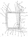
- a rear vehicle door 10 has a split side window, the front part 12 with a built-in side window blind according to the invention can be closed.
- a roller blind cassette 18 is fastened by fastening means 20, 22 to elements of the body or side door.
- the fastening means 20, 22 and the corresponding fastening means on the door or body are arranged so that the roller blind cassette and in particular the axis of rotation of a winding shaft, not shown in the roller blind cassette 18, are arranged at an acute angle 24 to the lower substantially horizontal window frame edge 16 is.
- a horizontal edge of the window frame it can also have a kink, a shoulder or a slight inclination of a few degrees with respect to the horizontal.
- a pull rod 26 is located on the upper edge of the roller blind 14 of the side window roller blind 14.
- the pull rod is also shown as a dashed contour 28 in FIG. 1 for illustration of the lowered basic position of the side window roller blind, in which it is complete lowered below the lower edge of the window frame 16 and thus hidden behind the door trim, not shown.
- the roller blind is already pulled further out of the roller blind cassette 18 as a function of the course of the window frame upper edge or the thereto adapted pull rod 26 on its rear side than on the front side.
- the ends of the pull rod 26 thus have different distances from the axis of rotation 48 of the winding shaft in the basic position.
- This pre-extract, together with the inclined installation position of the winding shaft in the roller blind cassette 18 ensures that the side window blind 14 can be unwound in a straight line from this.
- a winding shaft so a simple cylindrical shaft can thus be provided regardless of the window shape.
- the closed by the side window blind 14 part 12 of the side window has a relative to the vertical inclined front and a parallel rear window frame edge 34, 36.
- This is a particularly simple body design, in which for the side window roller blind a substantially uniform over its entire length roller blind is needed.
- Side windows which have no parallel front and rear edges and expire, for example in the form of a triangular window, allows the oblique, perpendicular to at least one of the leading or trailing edge mounting position of the winding shaft a simple design of the same.
- the side window roller blind on a drive motor 30 which flanged to the roller blind cassette and with a drive shaft. 32 is connected.
- This has at a distance from the width of the side window 12, or more precisely at the distance of the parallel front and rear edges 34, 36 of the side window 12 concealing roller blind 14, each having a gear element in the form of a gear 38, 40.
- the gears 38, 40 engage in a respectively associated drive cable 42 and 44, respectively.
- the drive cable consists of an inner wire rope around which an outer wire is helically wound.
- Such drive or brush cables can be loaded on both train and pressure, d. H. transmit a driving force. In the helical winding of the outer wire engages the teeth of the gears 38 and 40 gear-like.
- Each of the drive cables 42, 44 is connected at its upper end to the drawbar 26. Since the side window roller blind 14 can be unwound in a straight line from this due to the inclined installation position of the winding shaft, the drive cables are installed perpendicular to the axis of rotation of the winding shaft and the drive elements can be designed with the same translation. For this purpose, the same parts are used.
- the drive cables are on the one hand stiff enough to lift the pull rod 26 as a push element and thus deduct the roller blind connected to the pull rod 26 against the tensile force of a spring connected to the winding shaft of the winding shaft.
- Such drive cables are flexible enough that they can be deflected by one or more deflection points within the door or side panel of the vehicle body and thus stowed there.
- the drawbar 26 and the drive cables are guided parallel to the front and rear side window edge and can also be hidden there behind the side door or side panel of the body.
Abstract
Description
Die Erfindung betrifft ein Seitenfensterrollo für Kraftfahrzeuge mit einer Rollobahn zum Abdecken eines Seitenfensters des Kraftfahrzeugs, einer unterhalb des Seitenfensters eingebauten Aufrolleinrichtung mit einer um eine Drehachse drehbaren Wickelwelle für die Rollobahn und einer Antriebseinrichtung mit an der Rollobahn angreifenden Vorschubmitteln. Derartige Seitenfensterrollos sind bekannt. Sie werden unter der Türverkleidung oder der Seitenverkleidung im Fondbereich oder auch im Gepäckbereich horizontal an der Kraftfahrzeugkarosserie angebaut.The invention relates to a side window roller blind for motor vehicles with a roller blind for covering a side window of the motor vehicle, a built-in below the side window retractor with a rotatable about a rotation axis winding shaft for the roller blind and a drive device acting on the roller blind feed means. Such side window blinds are known. They are mounted under the door trim or the side trim in the rear area or in the luggage area horizontally to the vehicle body.
Aus Gründen zunehmender Individualisierung des Designs weisen Seitenfenster moderner Kraftfahrzeuge unterschiedliche Formen auf. Beispielsweise werden die B-Säulen von Fahrzeugen oftmals nicht länger senkrecht, sondern nach hinten geneigt angeordnet, um einen dynamischeren Eindruck zu erzielen. Entsprechend weisen Seitenfenster in den vorderen und/oder hinteren Türen bzw. in der Karosserie geneigte, vordere und/oder hintere Fensterrahmenkanten auf. Ebenfalls aus ästhetischen oder aerodynamischen Gründen ist die obere Fensterrahmenkante oft nicht länger im Wesentlichen horizontal bzw. parallel zur unteren Fensterrahmenkante angeordnet, sondern weist dieser gegenüber einen Neigungswinkel auf und ist oftmals gekrümmt.For reasons of increasing individualization of the design, side windows of modern motor vehicles have different shapes. For example, the B-pillars of vehicles are often no longer perpendicular, but tilted backwards for a more dynamic impression. Correspondingly, side windows in the front and / or rear doors or in the body have inclined, front and / or rear window frame edges. Also, for aesthetic or aerodynamic reasons, the upper edge of the window frame is often no longer substantially horizontal or parallel to the lower edge of the window frame, but has an angle of inclination with respect to it and is often curved.
Seitenfensterrollos für Seitenfenster mit den genannten Merkmalen weisen daher bekanntermaßen eine Rollobahn mit einem entsprechend individualisierten Zuschnitt auf. Die Fensterform erfordert ferner, dass Seitenfensterrollos entlang koplexerer Bewegungsbahnen geschlossen und geöffnet werden müssen, wobei die Aufrolleinrichtung wie auch die Antriebseinrichtung eingerichtet sind, das Rollo der Kontur des Fensters folgend auf- bzw. abzuwickeln. Hierzu sind beispielsweise ungleiche Antriebsübersetzungen für die Rollobahn entlang der Fensterrahmenvorderkante bzw. -hinterkante vorgesehen. Ferner ist es bekannt, die Wickelwelle kegelförmig auszugestalten, um zu einer geeigneten Abwicklung der Rollobahn zu gelangen.Side window roller blinds for side windows with the mentioned features are therefore known to have a roller blind with a correspondingly individualized Cut to size. The window shape further requires that side window blinds must be closed and opened along more complex trajectories, the retractor and the drive means being arranged to roll up or down the shade of the contour of the window. For this purpose, for example, unequal drive ratios for the blind sheet along the window frame leading edge or trailing edge are provided. Furthermore, it is known to design the winding shaft cone-shaped in order to arrive at a suitable development of the roller blind.
Unterschiedliche Getriebe für die Antriebseinrichtung und/oder unterschiedliche Ausprägungen der Aufrolleinrichtung sind somit erforderlich, um eine Anpassung an die Vielzahl unterschiedlicher Seitenfensterkonturen von Fahrzeugtyp zu Fahrzeugtyp und selbst innerhalb desselben Fahrzeugs zu ermöglichen. Ein Nachteil der bekannten Seitenfensterrollos ist demnach, dass eine Vielzahl individuell angepasster Einzelteile für jedes Seitenfenster benötigt wird. Die Produktionskosten steigen folglich.Different transmissions for the drive device and / or different forms of the retractor are thus required to allow adaptation to the plurality of different side window contours from vehicle type to vehicle type and even within the same vehicle. A disadvantage of the known side window blinds is therefore that a large number of individually adapted items for each side window is needed. The production costs rise accordingly.
Aufgabe der Erfindung ist es daher, ein Seitenfensterrollo zu schaffen, das trotz seiner Nutzbarkeit für eine Vielzahl unterschiedlicher Seitenfenster einen höheren Grad an Universalität aufweist und somit kostengünstiger hergestellt werden kann.The object of the invention is therefore to provide a side window roller blind, which despite its usability for a variety of different side windows has a higher degree of universality and thus can be produced more cheaply.
Die Aufgabe wird durch ein Seitenfensterrollo für Kraftfahrzeuge der eingangs genannten Art gelöst, bei dem die Drehachse der Wickelwelle unter einem spitzen Winkel zur Unterkante des Seitenfensters angeordnet und die Wickelwelle soweit unter die untere Fensterrahmenkante abgesenkt ist, dass ein eine Oberkante bildendes freies Ende der Rollobahn in einer heruntergefahrenen Grundstellung des Seitenfensterrollos unterhalb der Unterkante des Seitenfensters angeordnet ist.The object is achieved by a side window roller blind for motor vehicles of the type mentioned, in which the axis of rotation of the winding shaft is arranged at an acute angle to the lower edge of the side window and the winding shaft is lowered below the lower window frame edge, that a top edge forming free end of the blind sheet in a shut down basic position of the side window roller blind is arranged below the lower edge of the side window.
Eine schräge Einbaulage der Wickelwelle bzw. deren zentraler Drehachse bewirkt, dass der Geometrie einer Vielzahl von Seitenfenstern, insbesondere wenn beispielsweise die B-Säule der Kraftfahrzeuge unterschiedliche Neigungen gegenüber der Vertikalen aufweisen, bereits auf einfache Weise Rechnung getragen werden kann, da unabhängig von der Neigung eine zylindrische Wickelwelle eingesetzt werden kann. Die Rollobahn wird gleichförmig, d.h. entlang ihrer Vorderkante und ihrer Hinterkante mit gleicher Geschwindigkeit ab- und aufgewickelt, so dass keine unterschiedlichen Getriebeübersetzungen nötig sind. Ein Absenken der Einbauposition der Wickelwelle bewirkt darüber hinaus, dass die Rollobahn nicht vollständig aufgewickelt werden muss, um unter die unteren Fensterrahmenkante abgesenkt werden zu können.An oblique installation position of the winding shaft or its central axis of rotation causes the geometry of a plurality of side windows, in particular if, for example, the B-pillar of the motor vehicles different inclinations With respect to the vertical, can already be taken into account in a simple manner, since regardless of the inclination, a cylindrical winding shaft can be used. The roller blind is uniform, ie along its leading edge and its trailing edge at the same speed off and wound, so that no different gear ratios are needed. A lowering of the installation position of the winding shaft moreover causes that the roller blind does not have to be completely wound up in order to be able to be lowered below the lower edge of the window frame.
Vorzugsweise weist das Seitenfensterrollo eine im Bereich des freien Endes der Rollobahn befestigte Zugstange auf, an der zum Abwickeln die Vorschubmittel angreifen und die der Kontur der oberen Fensterrahmenkante im geschlossenen Zustand des Rollos im Wesentlichen folgt. Mit der Zugstange wird die Oberkante der Rollobahn stabilisiert, so dass die Antriebskräfte gleichmäßig entlang der gesamten Breite der Rollobahn angreifen. Gleichzeitig sorgt die der Kontur der oberen Fensterrahmenkante folgende Zugstange für einen dichten Abschluss im geschlossenen Zustand des Rollos.The side window roller blind preferably has a pull rod fastened in the region of the free end of the roller blind web, on which the feed means engage for unwinding and which substantially follows the contour of the upper window frame edge in the closed state of the roller blind. With the drawbar, the upper edge of the roller blind is stabilized, so that the driving forces act evenly along the entire width of the roller blind. At the same time, the pull rod following the contour of the upper window frame edge ensures a tight seal in the closed state of the roller blind.
Hierbei weisen die Enden der Zugstange in der Grundstellung vorzugsweise unterschiedliche Abstände von der Drehachse der Wickelwelle auf.In this case, the ends of the pull rod in the basic position preferably at different distances from the axis of rotation of the winding shaft.
Wegunterschiede der Rollobahn entlang Ihrer Vorder- und Hinterkante können durch einen solchen in der heruntergefahrenen Grundstellung nicht aufgewickelten Vor-Auszug der Rollobahn ausgeglichen werden. Die Länge des Vor-Auszugs kann durch ein entsprechend weites Absenken der Wickelwelle innerhalb der Tür- oder Karosserieverkleidung des Kraftfahrzeugs ausgeglichen werden. Hierdurch ergeben sich mehr Gestaltungsmöglichkeiten für die Ausgestaltung des freien Endes der Rollobahn bzw. der Zugstange, so dass deren Oberkante an eine Vielzahl verschiedener oberer Fensterrahmenkanten angepasst werden kann.Path differences of the roller blind along its front and rear edges can be compensated for by such a pre-extension of the roller blind not wound up in the lowered basic position. The length of the pre-extension can be compensated by a correspondingly far lowering the winding shaft within the door or body panel of the motor vehicle. This results in more design options for the design of the free end of the roller blind or the pull rod, so that the upper edge can be adapted to a variety of different upper window frame edges.
In einer bevorzugten Ausführungsform weisen die Vorschubmittel zwei als Antriebskabel mit einem schraubenförmig umwickelten Draht ausgebildete biegsame Schubelemente auf, die an jeweils einem Ende der Zugstange angreifen. Dabei ist die Drehachse der Wickelwelle vorzugsweise senkrecht zur Bewegungsrichtung der beiden Antriebskabel angeordnet.In a preferred embodiment, the feed means comprise two formed as a drive cable with a helically wound wire flexible pushers that engage each one end of the pull rod. In this case, the axis of rotation of the winding shaft is preferably arranged perpendicular to the direction of movement of the two drive cables.
Bei einer typischen Karosserieform, bei der das Seitenfenster durch eine vordere und/oder eine hintere gegenüber der Vertikalen geneigte Fensterrahmenkante begrenzt ist, ist die Drehachse der Wickelwelle dann bevorzugt senkrecht zu der vorderen und/oder hinteren Fensterrahmenkante angeordnet. In diesem Fall kann die Vorder- bzw. die Hinterkante der Rollobahn und die an dieser über die Zugstange angreifenden Antriebskabel im Bereich der Fensterrahmenvorder- und -hinterkante geführt und ggf. von der Verkleidung verdeckt werden.In a typical body shape in which the side window is bounded by a front and / or a rear window frame edge inclined relative to the vertical, the axis of rotation of the winding shaft is then preferably arranged perpendicular to the front and / or rear window frame edge. In this case, the leading edge or the trailing edge of the roller blind and the drive cable acting on the latter via the pull rod can be guided in the area of the window frame leading and trailing edge and possibly covered by the covering.
Die Antriebseinrichtung weist in einer weiteren vorteilhaften Ausgestaltung einen Antriebsmotor, eine zur Drehachse der Wickelwelle parallel ausgerichtete, mit dem Antriebsmotor verbundene Antriebswelle und zwei mit der Antriebswelle verbundene, gleichwirkende Getriebeelemente zur Kraftübertragung auf (z. B. Zahnräder, Ritzel oder dgl.), die jeweils mit einem der Antriebskabel in Eingriff stehen. Bei dieser Ausführungsform kann eine Vielzahl gleichartiger Bauelemente innerhalb desselben Seitenfensterrollos verwendet werden. Darüber hinaus können dieselben Bauelemente (z. B. die Getriebeelemente, die Antriebswelle, die Antriebskabel und der Antriebsmotor) für verschiedenartige Seitenfenster verwendet werden. Lediglich die Zugstange muss aufgrund der jeweiligen unterschiedlich ausgeformten oberen Fensterrahmenkante angepasst werden. Letzteres gilt auch für den Zuschnitt der Rollobahn.In a further advantageous refinement, the drive device has a drive motor, a drive shaft which is aligned parallel to the axis of rotation of the winding shaft and two drive elements which are connected to the drive shaft and transmit power (eg gears, pinions or the like) each in engagement with one of the drive cables. In this embodiment, a plurality of similar components can be used within the same side window roller blind. In addition, the same components (eg, the gear elements, the drive shaft, the drive cables and the drive motor) can be used for various side windows. Only the drawbar must be adjusted due to the respective differently shaped upper edge of the window frame. The latter also applies to the cutting of the roller blind.
Weitere Aufgaben, Merkmale und Vorteile werden nun anhand eines Ausführungsbeispiels mit Hilfe der Zeichnung näher erläutert. Es zeigt:
- Fig. 1 ein Ausführungsbeispiel des erfindungsgemäßen, in die Seitentür einer Kraftfahrzeugkarosserie eingebauten Seitenfensterrollos.
- Fig. 1 shows an embodiment of the invention, built into the side door of a motor vehicle body side window blinds.
Gemäß dem in Fig. 1 gezeigten Ausführungsbeispiel weist eine hintere Kraftfahrzeugtür 10 ein geteiltes Seitenfenster auf, dessen vorderer Teil 12 mit einem erfindungsgemäßen, eingebauten Seitenfensterrollo verschließbar ist. Unterhalb einer unteren Fensterrahmenkante 16 ist eine Rollokassette 18 durch Befestigungsmittel 20, 22 an Elementen der Karosserie bzw. Seitentür befestigt. Die Befestigungsmittel 20, 22 und die korrespondierenden Befestigungsmittel an der Tür bzw. Karosserie sind so angeordnet, dass die Rollokassette und insbesondere die Drehachse einer in der Rollokassette 18 befindlichen, nicht dargestellten Wickelwelle unter einen spitzen Winkel 24 zu der unteren im Wesentlichen horizontalen Fensterrahmenkante 16 angeordnet ist. Anstelle einer horizontale Fensterrahmenkante kann diese auch einen Knick, Absatz oder eine geringe Neigung von wenigen Grad gegenüber der Horizontalen aufweisen.According to the embodiment shown in Fig. 1, a
An der Oberkante der ausgezogen dargestellten Rollobahn 14 des Seitenfensterrollos 14 befindet sich zur Stabilisierung des freien Endes der Rollobahn 14 eine Zugstange 26. Die Zugstange ist ferner als gestrichelte Kontur 28 in Fig. 1 zur Illustration der heruntergefahrenen Grundstellung des Seitenfensterrollos dargestellt, in der dieses vollständig unter die untere Fensterrahmenkante 16 abgesenkt und somit hinter der nicht dargestellten Türverkleidung verborgen ist. In dieser Grundstellung ist die Rollobahn in Abhängigkeit von dem Verlauf der Fensterrahmenoberkante bzw. der daran angepassten Zugstange 26 auf seiner hinteren Seite bereits weiter aus der Rollokassette 18 herausgezogen als auf der Vorderseite. Die Enden der Zugstange 26 weisen in der Grundstellung also unterschiedliche Abstände von der Drehachse 48 der Wickelwelle auf. Dieser Vor-Auszug sorgt zusammen mit der geneigten Einbauposition der Wickelwelle in der Rollokassette 18 dafür, dass das Seitenfensterrollo 14 geradlinig von dieser abgewickelt werden kann. Als Wickelwelle kann also unabhängig von der Fensterform eine einfache zylinderförmige Welle vorgesehen werden.For the stabilization of the free end of the roller blind 14, a
Der von dem Seitenfensterrollo 14 verschlossene Teil 12 des Seitenfensters weist eine gegenüber der Vertikalen geneigte vordere und eine dazu parallele hintere Fensterrahmenkante 34, 36 auf. Dies stellt eine besonders einfache Karosseriebauform dar, bei der für das Seitenfensterrollo eine im Wesentlichen über seine gesamte Länge gleich breite Rollobahn benötigt wird. Aber auch für Seitenfenster, die keine parallelen Vorder- und Hinterkanten haben und beispielsweise in Form eines Dreiecksfensters auslaufen, ermöglicht die schräge, zu wenigstens einer der Vorder- oder Hinterkante senkrechte Einbaulage der Wickelwelle eine einfache Bauform derselben.The closed by the side window blind 14
Als Antriebseinrichtung weist das Seitenfensterrollo einen Antriebsmotor 30 auf, der an die Rollokassette angeflanscht und mit einer Antriebswelle. 32 verbunden ist. Diese weist im Abstand der Breite des Seitenfensters 12, bzw. genauer gesagt im Abstand der parallelen Vorder- und Hinterkanten 34, 36 der das Seitenfenster 12 verdeckenden Rollobahn 14, jeweils ein Getriebeelement in Form eines Zahnrads 38, 40 auf. Die Zahnräder 38, 40 greifen in ein jeweils zugeordnetes Antriebskabel 42 bzw. 44 ein. Das Antriebskabel besteht aus einem innenliegenden Drahtseil, um welches ein äußerer Draht schraubenförmig gewickelt ist. Solche Antriebs- oder Bürstenkabel können sowohl auf Zug als auch Druck belastet werden, d. h. eine Antriebskraft übertragen. In die schraubenförmige Wicklung des äußeren Drahts greift dazu die Zahnung der Zahnräder 38 bzw. 40 getriebeartig ein. Jedes der Antriebskabel 42, 44 ist an seinem oberen Ende mit der Zugstange 26 verbunden. Da das Seitenfensterrollo 14 aufgrund der schrägen Einbauposition der Wickelwelle geradlinig von dieser abgewickelt werden kann, sind die Antriebskabel senkrecht zu der Drehachse der Wickelwelle eingebaut und die Antriebselemente können mit gleicher Übersetzung ausgelegt werden. Es kommen hierfür jeweils gleiche Teile zu Einsatz.As a drive device, the side window roller blind on a
Die Antriebskabel sind einerseits steif genug, um als Schubelement die Zugstange 26 anzuheben und damit die mit der Zugstange 26 verbundene Rollobahn gegen die Zugkraft einer mit der Wickelwelle verbundenen Feder von der Wickelwelle abzuziehen. Andererseits sind derartige Antriebskabel flexibel genug, dass sie um eine oder mehrere Umlenkstellen innerhalb der Tür- oder Seitenverkleidung der Kraftfahrzeugkarosserie umgelenkt und somit dort verstaut werden können. Die Zugstange 26 bzw. die Antriebskabel werden parallel zu der vorderen bzw. hinteren Seitenfensterkante geführt und können auch dort hinter der Seitentür- bzw. Seitenteilverkleidung der Karosserie verdeckt werden.The drive cables are on the one hand stiff enough to lift the
Claims (8)
dadurch gekennzeichnet, dass die Drehachse (48) der Wickelwelle unter einem spitzen Winkel zur Unterkante (16) des Seitenfensters (12) angeordnet und die Wickelwelle soweit unter die untere Fensterrahmenkante abgesenkt ist, dass ein eine Oberkante bildendes freies Ende der Rollobahn (14) in einer heruntergefahrenen Grundstellung des Seitenfensterrollos unterhalb der Unterkante (16) des Seitenfensters (12) angeordnet ist.Side window roller blind for motor vehicles with a roller blind (14) for covering a side window (12) of the motor vehicle, a retractor installed beneath the side window with a winding shaft for the roller blind and a drive device with feed means engaging on the roller blind,
characterized in that the axis of rotation (48) of the winding shaft at an acute angle to the lower edge (16) of the side window (12) and the winding shaft is lowered so far below the lower window frame edge, that a top edge forming free end of the blind sheet (14) in a shut down basic position of the side window roller blind below the lower edge (16) of the side window (12) is arranged.
gekennzeichnet durch eine im Bereich des freien Endes der Rollobahn (14) befestigte Zugstange (26), an der zum Abwickeln die Vorschubmittel angreifen und die der Kontur der oberen Fensterrahmenkante im geschlossenen Zustand des Seitenfensterrollos (14) im Wesentlichen folgt.Side window roller blind according to claim 1,
characterized by a in the region of the free end of the roller blind (14) attached to the drawbar (26), to attack the feed means for unwinding and the contour of the upper edge of the window frame in the closed state of the side window roller blind (14) substantially follows.
dadurch gekennzeichnet, dass die Enden der Zugstange (26) in der Grundstellung unterschiedliche Abstände von der Drehachse (48) der Wickelwelle aufweisen.Side window roller blind according to claim 2,
characterized in that the ends of the drawbar (26) in the basic position have different distances from the axis of rotation (48) of the winding shaft.
dadurch gekennzeichnet, dass die Vorschubmittel wenigstens ein biegsames Schubelement umfassen, das in seiner Längsausdehnung an wenigstens einer Umlenkstelle umgelenkt ist.Side window roller blind according to one of the preceding claims,
characterized in that the feed means comprise at least one flexible thrust element, which is deflected in its longitudinal extent at least one deflection point.
dadurch gekennzeichnet, dass die Vorschubmittel zwei als Antriebskabel (42, 44) mit einem schraubenförmig umwickelten Draht ausgebildete biegsame Schubelemente aufweisen, die an jeweils einem Ende der Zugstange (26) angreifen.Side window roller blind according to claim 4,
characterized in that the advancing means comprise two flexible push elements formed as a drive cable (42, 44) with a helically wound wire, which engage at one end of the pull rod (26).
dadurch gekennzeichnet, dass die Drehachse (48) der Wickelwelle senkrecht zur Bewegungsrichtung der beiden Antriebskabel (42, 44) angeordnet ist.Side window roller blind according to claim 5,
characterized in that the axis of rotation (48) of the winding shaft perpendicular to the direction of movement of the two drive cables (42, 44) is arranged.
dadurch gekennzeichnet, dass die Antriebseinrichtung einen Antriebsmotor (30), eine zur Drehachse (48) der Wickelwelle parallel ausgerichtete, mit dem Antriebsmotor (30) verbundene Antriebswelle (32) und zwei mit der Antriebswelle verbundene gleichwirkende Getriebeelemente (38, 40) zur Kraftübertragung aufweist, die jeweils mit einem der Antriebskabel (42, 44) in Eingriff stehen.Side window roller blind according to claim 5 or 6,
characterized in that the drive means comprises a drive motor (30), a parallel to the axis of rotation (48) of the winding shaft, connected to the drive motor (30) drive shaft (32) and two connected to the drive shaft equivalent acting transmission elements (38, 40) for transmitting power each engaging with one of the drive cables (42, 44).
dadurch gekennzeichnet, dass die Wickelwelle zylinderförmig ist.Side window roller blind according to one of the preceding claims,
characterized in that the winding shaft is cylindrical.
Priority Applications (1)
| Application Number | Priority Date | Filing Date | Title |
|---|---|---|---|
| PL05027914T PL1674312T3 (en) | 2004-12-22 | 2005-12-20 | Roller blind for vehicle side window |
Applications Claiming Priority (1)
| Application Number | Priority Date | Filing Date | Title |
|---|---|---|---|
| DE202004019785U DE202004019785U1 (en) | 2004-12-22 | 2004-12-22 | Side window roller blind for motor vehicles |
Publications (3)
| Publication Number | Publication Date |
|---|---|
| EP1674312A2 true EP1674312A2 (en) | 2006-06-28 |
| EP1674312A3 EP1674312A3 (en) | 2008-05-14 |
| EP1674312B1 EP1674312B1 (en) | 2010-01-27 |
Family
ID=34259009
Family Applications (1)
| Application Number | Title | Priority Date | Filing Date |
|---|---|---|---|
| EP05027914A Active EP1674312B1 (en) | 2004-12-22 | 2005-12-20 | Roller blind for vehicle side window |
Country Status (4)
| Country | Link |
|---|---|
| EP (1) | EP1674312B1 (en) |
| AT (1) | ATE456472T1 (en) |
| DE (2) | DE202004019785U1 (en) |
| PL (1) | PL1674312T3 (en) |
Families Citing this family (4)
| Publication number | Priority date | Publication date | Assignee | Title |
|---|---|---|---|---|
| DE102005057248B4 (en) * | 2005-11-29 | 2010-09-16 | Johnson Controls Interiors Gmbh & Co. Kg | Flush-mounted around the parapet of a side panel of a motor vehicle integrated sun blind |
| ATE505352T1 (en) | 2006-09-27 | 2011-04-15 | Bos Gmbh | ROLLER BLIND WITH UNDERCUT-FREE GUIDE RAIL |
| DE102007012281A1 (en) * | 2007-03-09 | 2008-09-11 | Bos Gmbh & Co. Kg | Automatically operated side window blind |
| DE102012211552A1 (en) * | 2012-07-03 | 2014-01-09 | Bos Gmbh & Co. Kg | Moving body part e.g. tailgate, for passenger car, has shading device comprising sheet with extension profile, where profile and/or side edges at shading end position of sheet of panel arrangement is/are partially covered by inner lining |
Citations (3)
| Publication number | Priority date | Publication date | Assignee | Title |
|---|---|---|---|---|
| US6047762A (en) | 1998-03-20 | 2000-04-11 | Prince Corporation | Shade control for a vehicle window |
| EP1149718A2 (en) | 2000-04-25 | 2001-10-31 | BOS GmbH & Co. KG | Roller blind for side-windows with a slit cover |
| EP1418073A1 (en) | 2002-10-17 | 2004-05-12 | BOS GmbH & Co. KG | Roller blind with lid on the extract slot |
-
2004
- 2004-12-22 DE DE202004019785U patent/DE202004019785U1/en not_active Expired - Lifetime
-
2005
- 2005-12-20 PL PL05027914T patent/PL1674312T3/en unknown
- 2005-12-20 EP EP05027914A patent/EP1674312B1/en active Active
- 2005-12-20 AT AT05027914T patent/ATE456472T1/en not_active IP Right Cessation
- 2005-12-20 DE DE502005008945T patent/DE502005008945D1/en active Active
Patent Citations (3)
| Publication number | Priority date | Publication date | Assignee | Title |
|---|---|---|---|---|
| US6047762A (en) | 1998-03-20 | 2000-04-11 | Prince Corporation | Shade control for a vehicle window |
| EP1149718A2 (en) | 2000-04-25 | 2001-10-31 | BOS GmbH & Co. KG | Roller blind for side-windows with a slit cover |
| EP1418073A1 (en) | 2002-10-17 | 2004-05-12 | BOS GmbH & Co. KG | Roller blind with lid on the extract slot |
Also Published As
| Publication number | Publication date |
|---|---|
| ATE456472T1 (en) | 2010-02-15 |
| PL1674312T3 (en) | 2010-09-30 |
| EP1674312A3 (en) | 2008-05-14 |
| DE202004019785U1 (en) | 2005-03-03 |
| EP1674312B1 (en) | 2010-01-27 |
| DE502005008945D1 (en) | 2010-03-18 |
Similar Documents
| Publication | Publication Date | Title |
|---|---|---|
| EP1588880B1 (en) | Roller blind for sliding roof assembly | |
| EP1905625B1 (en) | Roller blind with undercut-free guide rail | |
| EP1645448B1 (en) | Window roller blind for a vehicle window | |
| EP1794012A1 (en) | Blind arrangement for a motor vehicle | |
| EP2039547A2 (en) | Side window blind with intake aid | |
| DE102011113207B4 (en) | Vehicle blind arrangement and vehicle roof | |
| EP2465716B1 (en) | Roller blind system for a motor vehicle | |
| DE19750715C1 (en) | Roller shutter for motor vehicle roof | |
| DE202004014652U1 (en) | Door for a vehicle comprises a window blind with a blind path which moves parallel to the window pane using a mechanism a part of which is guided on the window lifter guide rail | |
| EP3310601A1 (en) | Shading device for a two-part side window arrangement of a motor vehicle | |
| EP1674312B1 (en) | Roller blind for vehicle side window | |
| DE102016212166A1 (en) | Shading device for a window of a motor vehicle | |
| EP1964700B1 (en) | Roller blind for vehicle window | |
| DE102008011505B4 (en) | Roller blind system for a vehicle | |
| DE102007035072B4 (en) | Roller blind for a motor vehicle side window with window dividing web | |
| WO2006063565A1 (en) | Blind for a vehicle window | |
| WO2019042742A1 (en) | Roller blind arrangement with winding shaft cladding tube | |
| DE10215322A1 (en) | Sun protection roller blind for side windows in motor vehicles has flexible winder shaft with roller length to prevent sun glare while covering minimum part of window | |
| DE202007008186U1 (en) | Sun protection roller blind for motor vehicles | |
| DE202004020106U1 (en) | Window roller blind for motor vehicle window, has sliding units connected with section that is detachable from winding shaft and with drive device over drive section, and drive adjustment device for modifying length of drive section | |
| EP0529591B1 (en) | Roller blind, preferably for vehicle rear windows | |
| DE202006017842U1 (en) | Window blind for motor vehicles has guide rail on each side of material web, two band-form operating components allocated to respective guide rails, and two drive pinions each allocated to respective operating component | |
| DE10316785B4 (en) | net device | |
| DE102008061215A1 (en) | Motor vehicle, has roller blind wound using ropes and brought into extended position, where ropes are wound to portion of rotatable winding bodies that are fastened to shaft that is displaced by blind shaft | |
| DE202007008178U1 (en) | Side window roller blind for motor vehicle, has telescopic rod extendable by pressure-rigid, linear, flexible element e.g. tooth cord, and pivotable during engaging completely within side door of motor vehicle |
Legal Events
| Date | Code | Title | Description |
|---|---|---|---|
| PUAI | Public reference made under article 153(3) epc to a published international application that has entered the european phase |
Free format text: ORIGINAL CODE: 0009012 |
|
| AK | Designated contracting states |
Kind code of ref document: A2 Designated state(s): AT BE BG CH CY CZ DE DK EE ES FI FR GB GR HU IE IS IT LI LT LU LV MC NL PL PT RO SE SI SK TR |
|
| AX | Request for extension of the european patent |
Extension state: AL BA HR MK YU |
|
| PUAL | Search report despatched |
Free format text: ORIGINAL CODE: 0009013 |
|
| AK | Designated contracting states |
Kind code of ref document: A3 Designated state(s): AT BE BG CH CY CZ DE DK EE ES FI FR GB GR HU IE IS IT LI LT LU LV MC NL PL PT RO SE SI SK TR |
|
| AX | Request for extension of the european patent |
Extension state: AL BA HR MK YU |
|
| 17P | Request for examination filed |
Effective date: 20081114 |
|
| 17Q | First examination report despatched |
Effective date: 20081211 |
|
| AKX | Designation fees paid |
Designated state(s): AT BE BG CH CY CZ DE DK EE ES FI FR GB GR HU IE IS IT LI LT LU LV MC NL PL PT RO SE SI SK TR |
|
| GRAP | Despatch of communication of intention to grant a patent |
Free format text: ORIGINAL CODE: EPIDOSNIGR1 |
|
| GRAS | Grant fee paid |
Free format text: ORIGINAL CODE: EPIDOSNIGR3 |
|
| GRAA | (expected) grant |
Free format text: ORIGINAL CODE: 0009210 |
|
| AK | Designated contracting states |
Kind code of ref document: B1 Designated state(s): AT BE BG CH CY CZ DE DK EE ES FI FR GB GR HU IE IS IT LI LT LU LV MC NL PL PT RO SE SI SK TR |
|
| REG | Reference to a national code |
Ref country code: GB Ref legal event code: FG4D Free format text: NOT ENGLISH |
|
| REG | Reference to a national code |
Ref country code: CH Ref legal event code: EP |
|
| REG | Reference to a national code |
Ref country code: IE Ref legal event code: FG4D |
|
| REF | Corresponds to: |
Ref document number: 502005008945 Country of ref document: DE Date of ref document: 20100318 Kind code of ref document: P |
|
| REG | Reference to a national code |
Ref country code: RO Ref legal event code: EPE |
|
| REG | Reference to a national code |
Ref country code: NL Ref legal event code: VDEP Effective date: 20100127 |
|
| LTIE | Lt: invalidation of european patent or patent extension |
Effective date: 20100127 |
|
| PG25 | Lapsed in a contracting state [announced via postgrant information from national office to epo] |
Ref country code: ES Free format text: LAPSE BECAUSE OF FAILURE TO SUBMIT A TRANSLATION OF THE DESCRIPTION OR TO PAY THE FEE WITHIN THE PRESCRIBED TIME-LIMIT Effective date: 20100508 Ref country code: PT Free format text: LAPSE BECAUSE OF FAILURE TO SUBMIT A TRANSLATION OF THE DESCRIPTION OR TO PAY THE FEE WITHIN THE PRESCRIBED TIME-LIMIT Effective date: 20100527 Ref country code: IS Free format text: LAPSE BECAUSE OF FAILURE TO SUBMIT A TRANSLATION OF THE DESCRIPTION OR TO PAY THE FEE WITHIN THE PRESCRIBED TIME-LIMIT Effective date: 20100527 Ref country code: LT Free format text: LAPSE BECAUSE OF FAILURE TO SUBMIT A TRANSLATION OF THE DESCRIPTION OR TO PAY THE FEE WITHIN THE PRESCRIBED TIME-LIMIT Effective date: 20100127 Ref country code: NL Free format text: LAPSE BECAUSE OF FAILURE TO SUBMIT A TRANSLATION OF THE DESCRIPTION OR TO PAY THE FEE WITHIN THE PRESCRIBED TIME-LIMIT Effective date: 20100127 |
|
| REG | Reference to a national code |
Ref country code: IE Ref legal event code: FD4D |
|
| PG25 | Lapsed in a contracting state [announced via postgrant information from national office to epo] |
Ref country code: SI Free format text: LAPSE BECAUSE OF FAILURE TO SUBMIT A TRANSLATION OF THE DESCRIPTION OR TO PAY THE FEE WITHIN THE PRESCRIBED TIME-LIMIT Effective date: 20100127 Ref country code: FI Free format text: LAPSE BECAUSE OF FAILURE TO SUBMIT A TRANSLATION OF THE DESCRIPTION OR TO PAY THE FEE WITHIN THE PRESCRIBED TIME-LIMIT Effective date: 20100127 Ref country code: LV Free format text: LAPSE BECAUSE OF FAILURE TO SUBMIT A TRANSLATION OF THE DESCRIPTION OR TO PAY THE FEE WITHIN THE PRESCRIBED TIME-LIMIT Effective date: 20100127 |
|
| REG | Reference to a national code |
Ref country code: PL Ref legal event code: T3 |
|
| REG | Reference to a national code |
Ref country code: HU Ref legal event code: AG4A Ref document number: E008187 Country of ref document: HU |
|
| PG25 | Lapsed in a contracting state [announced via postgrant information from national office to epo] |
Ref country code: SE Free format text: LAPSE BECAUSE OF FAILURE TO SUBMIT A TRANSLATION OF THE DESCRIPTION OR TO PAY THE FEE WITHIN THE PRESCRIBED TIME-LIMIT Effective date: 20100127 Ref country code: IE Free format text: LAPSE BECAUSE OF FAILURE TO SUBMIT A TRANSLATION OF THE DESCRIPTION OR TO PAY THE FEE WITHIN THE PRESCRIBED TIME-LIMIT Effective date: 20100127 Ref country code: GR Free format text: LAPSE BECAUSE OF FAILURE TO SUBMIT A TRANSLATION OF THE DESCRIPTION OR TO PAY THE FEE WITHIN THE PRESCRIBED TIME-LIMIT Effective date: 20100428 Ref country code: EE Free format text: LAPSE BECAUSE OF FAILURE TO SUBMIT A TRANSLATION OF THE DESCRIPTION OR TO PAY THE FEE WITHIN THE PRESCRIBED TIME-LIMIT Effective date: 20100127 Ref country code: CY Free format text: LAPSE BECAUSE OF FAILURE TO SUBMIT A TRANSLATION OF THE DESCRIPTION OR TO PAY THE FEE WITHIN THE PRESCRIBED TIME-LIMIT Effective date: 20100127 |
|
| PG25 | Lapsed in a contracting state [announced via postgrant information from national office to epo] |
Ref country code: SK Free format text: LAPSE BECAUSE OF FAILURE TO SUBMIT A TRANSLATION OF THE DESCRIPTION OR TO PAY THE FEE WITHIN THE PRESCRIBED TIME-LIMIT Effective date: 20100127 Ref country code: BG Free format text: LAPSE BECAUSE OF FAILURE TO SUBMIT A TRANSLATION OF THE DESCRIPTION OR TO PAY THE FEE WITHIN THE PRESCRIBED TIME-LIMIT Effective date: 20100427 Ref country code: CZ Free format text: LAPSE BECAUSE OF FAILURE TO SUBMIT A TRANSLATION OF THE DESCRIPTION OR TO PAY THE FEE WITHIN THE PRESCRIBED TIME-LIMIT Effective date: 20100127 |
|
| PLBE | No opposition filed within time limit |
Free format text: ORIGINAL CODE: 0009261 |
|
| STAA | Information on the status of an ep patent application or granted ep patent |
Free format text: STATUS: NO OPPOSITION FILED WITHIN TIME LIMIT |
|
| 26N | No opposition filed |
Effective date: 20101028 |
|
| PG25 | Lapsed in a contracting state [announced via postgrant information from national office to epo] |
Ref country code: DK Free format text: LAPSE BECAUSE OF FAILURE TO SUBMIT A TRANSLATION OF THE DESCRIPTION OR TO PAY THE FEE WITHIN THE PRESCRIBED TIME-LIMIT Effective date: 20100127 |
|
| PG25 | Lapsed in a contracting state [announced via postgrant information from national office to epo] |
Ref country code: IT Free format text: LAPSE BECAUSE OF FAILURE TO SUBMIT A TRANSLATION OF THE DESCRIPTION OR TO PAY THE FEE WITHIN THE PRESCRIBED TIME-LIMIT Effective date: 20100127 |
|
| BERE | Be: lapsed |
Owner name: HS PRODUCTS ENGINEERING G.M.B.H. Effective date: 20101231 |
|
| PG25 | Lapsed in a contracting state [announced via postgrant information from national office to epo] |
Ref country code: MC Free format text: LAPSE BECAUSE OF NON-PAYMENT OF DUE FEES Effective date: 20101231 |
|
| REG | Reference to a national code |
Ref country code: CH Ref legal event code: PL |
|
| GBPC | Gb: european patent ceased through non-payment of renewal fee |
Effective date: 20101220 |
|
| REG | Reference to a national code |
Ref country code: FR Ref legal event code: ST Effective date: 20110831 |
|
| PG25 | Lapsed in a contracting state [announced via postgrant information from national office to epo] |
Ref country code: BE Free format text: LAPSE BECAUSE OF NON-PAYMENT OF DUE FEES Effective date: 20101231 |
|
| PG25 | Lapsed in a contracting state [announced via postgrant information from national office to epo] |
Ref country code: LI Free format text: LAPSE BECAUSE OF NON-PAYMENT OF DUE FEES Effective date: 20101231 Ref country code: CH Free format text: LAPSE BECAUSE OF NON-PAYMENT OF DUE FEES Effective date: 20101231 Ref country code: FR Free format text: LAPSE BECAUSE OF NON-PAYMENT OF DUE FEES Effective date: 20110103 |
|
| REG | Reference to a national code |
Ref country code: DE Ref legal event code: R082 Ref document number: 502005008945 Country of ref document: DE Representative=s name: BALS & VOGEL PATENTANWAELTE, DE |
|
| PG25 | Lapsed in a contracting state [announced via postgrant information from national office to epo] |
Ref country code: GB Free format text: LAPSE BECAUSE OF NON-PAYMENT OF DUE FEES Effective date: 20101220 |
|
| PG25 | Lapsed in a contracting state [announced via postgrant information from national office to epo] |
Ref country code: AT Free format text: LAPSE BECAUSE OF NON-PAYMENT OF DUE FEES Effective date: 20101220 |
|
| REG | Reference to a national code |
Ref country code: AT Ref legal event code: MM01 Ref document number: 456472 Country of ref document: AT Kind code of ref document: T Effective date: 20101220 |
|
| PG25 | Lapsed in a contracting state [announced via postgrant information from national office to epo] |
Ref country code: LU Free format text: LAPSE BECAUSE OF NON-PAYMENT OF DUE FEES Effective date: 20101220 |
|
| PG25 | Lapsed in a contracting state [announced via postgrant information from national office to epo] |
Ref country code: TR Free format text: LAPSE BECAUSE OF FAILURE TO SUBMIT A TRANSLATION OF THE DESCRIPTION OR TO PAY THE FEE WITHIN THE PRESCRIBED TIME-LIMIT Effective date: 20100127 |
|
| PGFP | Annual fee paid to national office [announced via postgrant information from national office to epo] |
Ref country code: HU Payment date: 20121219 Year of fee payment: 8 |
|
| PG25 | Lapsed in a contracting state [announced via postgrant information from national office to epo] |
Ref country code: HU Free format text: LAPSE BECAUSE OF NON-PAYMENT OF DUE FEES Effective date: 20131221 |
|
| REG | Reference to a national code |
Ref country code: DE Ref legal event code: R082 Ref document number: 502005008945 Country of ref document: DE Representative=s name: MATHYS & SQUIRE EUROPE PATENTANWAELTE PARTNERS, DE |
|
| PGFP | Annual fee paid to national office [announced via postgrant information from national office to epo] |
Ref country code: RO Payment date: 20230117 Year of fee payment: 18 |
|
| PGFP | Annual fee paid to national office [announced via postgrant information from national office to epo] |
Ref country code: PL Payment date: 20230120 Year of fee payment: 18 Ref country code: DE Payment date: 20230130 Year of fee payment: 18 |