EP1674288A1 - Binder and file - Google Patents
Binder and file Download PDFInfo
- Publication number
- EP1674288A1 EP1674288A1 EP03754109A EP03754109A EP1674288A1 EP 1674288 A1 EP1674288 A1 EP 1674288A1 EP 03754109 A EP03754109 A EP 03754109A EP 03754109 A EP03754109 A EP 03754109A EP 1674288 A1 EP1674288 A1 EP 1674288A1
- Authority
- EP
- European Patent Office
- Prior art keywords
- binding member
- binding
- distal end
- members
- binding members
- Prior art date
- Legal status (The legal status is an assumption and is not a legal conclusion. Google has not performed a legal analysis and makes no representation as to the accuracy of the status listed.)
- Withdrawn
Links
Images









Classifications
-
- B—PERFORMING OPERATIONS; TRANSPORTING
- B42—BOOKBINDING; ALBUMS; FILES; SPECIAL PRINTED MATTER
- B42F—SHEETS TEMPORARILY ATTACHED TOGETHER; FILING APPLIANCES; FILE CARDS; INDEXING
- B42F13/00—Filing appliances with means for engaging perforations or slots
- B42F13/16—Filing appliances with means for engaging perforations or slots with claws or rings
- B42F13/20—Filing appliances with means for engaging perforations or slots with claws or rings pivotable about an axis or axes parallel to binding edges
- B42F13/22—Filing appliances with means for engaging perforations or slots with claws or rings pivotable about an axis or axes parallel to binding edges in two sections engaging each other when closed
- B42F13/24—Filing appliances with means for engaging perforations or slots with claws or rings pivotable about an axis or axes parallel to binding edges in two sections engaging each other when closed wherein one section is in the form of fixed rods
Definitions
- This invention relates to a binding member and a file comprising an operating lever that can be used preferably in an office or the like.
- a binding member well-known is that comprises a pair of first binding members a , a and a pair of second binding members b, b corresponding to the first binding members a, a each of which is mounted on a base e , as shown in Fig. 15, wherein a bound state or a released state of papers or leaves can be realized by closing or opening a space between a distal end portion a1 of the first binding member a and a distal end portion b1 of the corresponding second binding member b through a relatively rotational movement of the first binding member a and the corresponding second binding member b.
- the binding member A comprises a release means c that applies a force toward a direction to open the space between the distal end portion a1 of the first binding member a and the distal end portion b1 of the corresponding second binding member b and an operating lever d that keeps the distal end portion a1 of the first binding member a and the distal end portion b1 of the corresponding second binding member b at a closed position by relatively rotating the first binding member a and the corresponding second binding member b in the teeth of the release means c.
- the binding member A is so arranged that the first and the second binding members a, b make a relatively rotational movement toward a direction to which a space between the distal end portions a1, b1 is closed in the teeth of a force applied by the release means c with an operation of the operating lever d downward so as to close the space between the distal end portions a1, b1 of the first and the second binding members a, b . Then the distal end portions a1, b1 of the first and the second binding members a, b make an abutting contact each other so that the space closes and the bound state of the papers or leaves can be kept by the first and the second binding members a , b under a keeping force by the operating lever d.
- the first and the second binding members a, b make a relative movement to open the space between the distal end portions a1, b1 so as to make a transition to be in a released state due to a force to open the space between the distal end portions a1, b1 applied to the first and the second binding members a , b by the release means c.
- Each of the distal end portions a1, b1 of the first and the second binding members a , b has a concave-convex arrangement to smoothly fit each other along a direction to open or close as shown in Fig. 16 (a), and makes an abutting engagement each other so as to form an arch shape with the first and the second binding members a, b .
- first and the second binding members a , b form an arch shape in a state the space is closed, a substantial area to bind the papers or leaves is a rising portion of the second binding member b rising generally vertically from the base e and a top head portion T only serves as an area to pass the papers or leaves at a time to access contents of the papers or leaves or to add or remove papers or leaves.
- a distance between a proximal end portion a2 of the first binding member a to the distal end portion a1 thereof becomes long more than necessary due to the top head portion T , which tends to cause an elastic transformation when an external force is applied to a side of the distal end portions a1 b1, thereby to cause the above-mentioned problems more prominently.
- a dead space D is formed between a front cover sheet B1 and a rear cover sheet B2 as shown in Fig. 17 due to a shape of the top head portion T , thereby to drop an efficiency of storing papers or leaves or to increase an outer shape of the file F unnecessarily.
- the present claimed invention mainly intends to provide a binding member and a file wherein the papers or leaves can be prevented from getting stuck between the binding members or dropping out of the binding member and the operating lever can be properly operated in spite of an external force accidentally applied to circumference of the distal end portions of the first and the second binding members with the first and the second binding members kept in a closed position by the operating lever.
- the present claimed invention has a following arrangement.
- a binding member in accordance with the present claimed invention comprises a pair of first binding members and a pair of second binding members corresponding to the first binding members wherein a bound state or a released state of papers or leaves can be realized by closing or opening a space between a distal end portion of the first binding member and a distal end portion of the corresponding second binding member through a relatively rotational movement of the first binding member and the corresponding second binding member, and further comprises a release means that applies a force toward a direction to open the space between the distal end portion of the first binding member and the distal end portion of the corresponding second binding member and an operating lever that keeps the distal end portion of the first binding member and the distal end portion of the corresponding second binding member at a closed position by relatively rotating the first binding member and the corresponding second binding member in the teeth of the release means.
- the binding member is characterized by that between the distal end portions arranged is an engaging portion that engages the distal end portions of the first and the corresponding second binding members through a temporary elastic transformation of at least either one of the first binding member and the corresponding second binding member and that prohibits the distal end portions from making a movement to open the space between the distal end portions by engaging the first and the corresponding second binding members further more tightly with making use of the force applied by the release means.
- both of the first and the second binding members make a relative rotational movement to a direction to close the space between the distal end portions in the teeth of the force applied by the release means.
- the engaging portion arranged between the distal end portions makes an engagement through the temporary elastic transformation of at least one of the first and the second binding members and a state in which papers or leaves are bound by the first and the second binding members can be obtained under a keeping force by the operating lever.
- the engaging portion is so arranged to make an engagement further more tightly by a force applied by the release means and the engaged state can not be released without a temporary elastic transformation of the first or the second binding member.
- the engaging portion is released from engagement. Since a force toward a direction to open the space between the distal end portions is applied to the first and the second binding members by the release means, the first and the second binding members make a relatively rotational movement toward a direction to open the space between the distal end portions so as to obtain a released state of binding.
- the engaging portion makes an engagement by making use of the temporary elastic transformation of the first binding members or the second binding members toward a direction to which a pair of the first binding members approach each other or a pair of the second binding members approach each other.
- the binding members can be elastically transformed toward a direction to approach each other with ease by pinching the first binding members with a finger or the like. As a result of this, it is possible to release a bound state of the first and the second binding members easily with a single hand.
- the engaging portion makes an engagement by making use of the temporary elastic transformation of the first binding members or the second binding members toward a direction to which the first binding members are separated from each other or the second binding members are separated from each other.
- the binding members can be elastically transformed toward a direction to be separated from each other with ease by separating the second binding members with both hands. As a result of this, it is possible to release a bound state of the first and the second binding members easily with both hands even though the first and the second binding members are given a relatively high rigidity.
- the engaging portion represented is that comprising an inward facing unciform portion arranged at either one of the first binding member and the second binding member and an outward facing unciform portion arranged at the other binding member.
- each of the first binding member and the second binding member is so arranged to rise with a proximal end portion thereof mounted on a base and a top head portion extending generally parallel to the base is arranged on at least either one of the first binding member and the second binding member locating at a rising end side in a state the space is closed.
- the top head portion extending generally parallel to the base is arranged at the rising side of at lease one of the first and the second binding members, a length from a proximal end portion of the binding member to a distal end portion thereof becomes small although a substantial amount to bind papers or leaves is the same when compared with a binding member whose top head portion is in a shape of an arch.
- the first and the second binding members are difficult to make an elastic transformation, thereby to effectively prevent a case such as a space between the distal end portions easily opens.
- the top head portion comprises the extending portion that extends generally parallel to the base, there is scarcely a dead space between the front cover sheet and the rear cover sheet when compared with a binding member whose top head portion is in a shape of an arch, thereby to effectively prevent a drop in storage efficiency and increasing an outer size of the file unnecessarily.
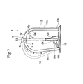
- Fig. 1 shows a general perspective view of a principal part showing a file 2 comprising a binding member 1, each of Fig. 2 through Fig. 5 shows a magnified front view of the binding member 1, a magnified left side view thereof, a magnified plane view thereof and a magnified right side view thereof.
- the file 2 comprises a cover sheet body 3 having a front cover sheet 31 and a rear cover sheet 32 each of which is continuous through a scroop 33 and the binding member 1 mounted on an inner face of the rear cover sheet 32.
- the binding member 1 comprises a pair of first binding members 11, 11 and a pair of second binding members 12, 12 corresponding to the first binding members 11, 11 each of which is mounted on a base 10 and has an arrangement that a space between a distal end portion 11a of the first binding member 11 and a distal end portion 12a of the corresponding second binding member 12 is closed or open through a relatively rotational movement of the first binding member 11 and the corresponding second binding member 12 as shown in Fig. 2.
- the binding member 1 further comprises a release means 4 that applies a force toward a direction to open the space between the distal end portion 11a of the first binding member 11 and the distal end portion 12a of the corresponding second binding member 12 (refer to Fig. 4) and an operating lever 5 that keeps the distal end portion 11a and the distal end portion 12a at a closed position by relatively rotating the first binding member 11 and the corresponding second binding member 12 in the teeth of the release means 4.
- first binding member 11 and the second binding member 12 form an arch-shaped closed loop in a state the space is closed.
- the first binding member 11 comprises a rising area 11x that rises from the base 10 in a generally vertical manner and a curved area 11y that curves gently from a distal end side of the rising area 11x toward the second binding member 12 as shown in Fig. 2.
- the second binding member 12 comprises a rising area 12x that rises from the base 10 by an elevation of a height a litter higher than the rising area 11x in the state the space is closed and a curved area 12y that curves from a distal end side of the rising area 12x toward the first binding member 11.
- the closed position of the distal end portions 11a and 12a locates at a position deviated from a top head portion T of an arch toward a side of the second binding member 12.
- each of the distal end portions 11b and 11b of a pair of the first binding members 11 and 11 is connected by a connecting portion 13 and a rotational axis portion 13a constituting both ends of the connecting portion 13 is rotatably mounted on a bearing 10a arranged on the base 10.
- a pair of the second binding members 12 and 12 are mounted with each of proximal end portions 12b fixed to the base 10.
- a bound state or a released state of papers or leaves can be realized by rotating the first binding member 11 with the rotational axis portion 13a used as a fulcrum so as to close or open the space between the distal end portion 11a of the first binding member 11 and the distal end portion 12a of the second binding member 12.
- the release means 4 has an arrangement that a crank axle 41 formed to be parallel to the rotational axis portion 13a by inflecting a part of the connecting portion 13 of the first binding member 11 in a shape of a crank is arranged at a position displaced from the rotational axis portion 13a and a blade spring 42 is arranged with its proximal end edge 42a fixed to the base 10 and its distal end edge 42b elastically making contact with the crank axle 41 upward from below as shown in Fig. 4.
- the release means 4 is so arranged that an elastic force is applied to the proximal end portion 11b locating at or near the closed position so as to push the first binding member 11 toward a direction to open the space through the connecting portion 13 by making use of an action of the blade spring 42.
- the operating lever 5 comprises, as shown in Fig. 3, a rotational arm 51, a transmission portion 52 that is integrally continuous to the rotational arm 51 toward a direction generally vertical thereto and an operating end portion 53 that is arranged to rise on a distal end side of the transmission portion 52 to be in a reverse L shape.
- a proximal end of the rotational arm 51 is rotatably mounted on a supporting portion 10b arranged to rise on the base 10 through an arm supporting axis 51a parallel to a direction to open or close the first and the second binding members 11, 12 and a roller 54 is mounted on an intersection of the rotational arm 51 and the transmission portion 52 through a roller supporting axis 54a generally parallel to the base 10.
- the operating end portion 53 locates at a position popped upward obliquely in a released position as shown by an imaginary line in Fig. 2 and Fig. 3 and the roller 54 makes a contact with the crank axel 41 of the connecting portion 13 at a position displaced from a center of the crank axel 41 in a condition of being able to roll.
- the rotational arm 51 makes a rotational movement around the arm supporting axis 51a and the roller 54 moves toward a center portion of the connecting portion 13 with rolling on the connecting portion 13 and pushes the connecting portion 13 downward in the teeth of the blade spring 42.
- the roller 54 When the operating lever 54 is operated upward from this position, the roller 54 is supposed to move on the connecting portion 13 pushed by the blade spring 42 toward a reverse direction from the above and the distal end portion 11a of the first binding member 11 is supposed to be separated from the distal end potion 12a of the second binding member 12 with the first binding member 11 rolling backward after the roller 54 passes the lowest point.
- the space between the distal end portions 11a, 12a is not open just by this operation due to an engaging portion 6 which will be described later.
- the engaging portion 6 that engages the first and the corresponding second binding members 11 and 12 through a temporary elastic transformation of the first binding member 11 or the corresponding second binding member 12 and that prohibits the distal end portions 11a and 12a from making a movement to open the space between the distal end portions 11a and 12a by engaging the first and the corresponding second binging members 11 and 12 further more tightly with making use of the force applied by the release means 4.
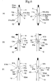
- the engaging portion 6 comprises, as shown in Fig. 5 and Fig. 6 (a) through (c), an outward facing unciform portion 61 in a shape of cutting a part of an outer side of the distal end portion 11a of the first binding member 11 and an inward facing unciform portion 62 in a shape of cutting a part of an inner side of the distal end portion 12a of the second binding member 12.
- Each of the outward facing unciform portion 61 and the inward facing unciform portion 62 has a chevron engaging portion 61a, 62a near the distal end thereof and a valley-shaped engaging portion 61b, 62b adjacent to a proximal end side of the chevron engaging portion 61b, 62b and an undercut portion 61ax, 62ax is formed at a boundary between the chevron engaging portion 61a, 62a and the valley-shaped engaging portion 61b, 62b as shown in Fig. 6 (b) and (c).
- the chevron engaging portion 61a (62a) of the unciform portion 61 (62) and the valley-shaped engaging portion 61b, 62b of the unciform portion 62 (61) are in a concave-convex relationship and each of the chevron engaging portions 61a and 62a has the same shape and each of the valley-shaped engaging portions 61b and 62b has the same shape.
- the chevron engaging portions 61a and 62a make an engagement each other further more tightly with robbing each other as the first binding members 11 and 11 temporarily make an elastic transformation toward a direction to approach each other and the second bind members 12 and 12 temporarily make an elastic transformation toward a direction to be separated from each other.
- the chevron engaging portion 61a (62a) falls in the valley-shaped engaging portion 62b (61b)
- the engaging portion 6 is formed as shown in Fig.
- first binding member 11 and the second binding member 12 are made to be a linear body apparently with forming a single continuous loop through the engaging portion 6. Then each of the first binding member 11 and the second binding member 12 is restored to an original state from an elastically transformed state.
- the first and the second binding members 11, 12 are kept to be in a state the space is closed wherein the space between the distal end portions 11a and 12a is closed not by a closing means to push the distal end portions 11a and 12a toward a direction to close the space but by the release means 4 to push the distal end portions 11a and 12a toward a direction to open the space.
- the reasons are that it possible to open or close the binding members 11, 12 smoothly without an excessive force to operate the binding members, to prevent noise due to a rapid movement or scary feeling in a case to close the space between the first binding member 11 and the second binding member 12 and to reduce a number of components because there is no need of additional component as a release means.
- a slit 31a is arranged on the front cover sheet 31 of the cover sheet body 3 at a position corresponding to an arch that is formed when the space between the first and the second binding members 11, 12 is closed and the top head portion T of the arch can be inserted into the slit 31a.
- a projection 31a1 that makes an engagement with an inner periphery of the arch is arranged on an opening edge of the slit 31a. The projection 31a1 and the slit 31a are to maintain a condition that the cover sheet body 3 is closed.
- the binding member 1 in accordance with the embodiment and the file 2 on which the binding member 1 is mounted are so arranged that the first and the second binding members 11 and 12 make a relatively rotational movement toward a direction to close the space between the distal end portions 11a and 12a in the teeth of the force applied by the release means 4 when the operating lever 5 is operated toward a direction to close the space between the distal end portions 11a and 12a of the first and the second binding members 11, 12.
- the engaging portion 6 that is arranged between the distal end portions 11a and 12a makes an engagement through a temporary elastic transformation of the first and the second binding members 11, 12 and a state in which papers or leaves are bound by the first and the second binding members 11 and 12 can be obtained as shown by a solid line in Fig. 1 through Fig. 4 under a keeping force by the operating lever 5.
- the engaging portion 6 is so arranged that the chevron engaging portion 61a (62a) and the valley-shaped engaging portion 62b (61b) make an engagement further more tightly by the force applied by the release means 4 toward a direction shown by an arrow in Fig. 6 (a) and the engaged state can not be released without applying a movement of a temporary elastic transformation as shown by an arrow in Fig. 6 (b).
- each of the undercut portions 61ax and 62ax locating at a basal part of the chevron engaging portion 61a, 62a shown in Fig. 6 (a), (c) makes an engagement each other when the first and the second binding members 11, 12 are to be released along an axial line.
- the top head portion T receives a reactive force from the floor, or an inertial gravity from the bound papers or leaves acts mainly on the second binding member 12 and then an outward external force to open the closed loop formed with the first and the second binding members 11, 12 acts on the first and the second binding members 11, 12.
- the space between the distal end portions 11a, 12a is kept in a closed condition because the engaging potion 6 has an arrangement of making an engagement in the teeth of a force to open the closed loop.
- the space between the distal end portions 11a, 12a can be kept in a closed condition since the engaging portion 6 engages itself further more tightly by its movement in either one of the two closed loops each consisting of the first binding member 11 and the second binding member 12 even though an external force is applied especially to the second binding member 12 toward the first binding member 11 to make the first and the second binding members 11, 12 improperly paired along a longitudinal direction of the scroop 33 due to an inertial gravity from the bound papers or leaves acting mainly on the second binding member 12.
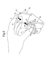
- the operating lever 5 is operated as shown by an arrow in Fig. 7 so as to release a keeping force to keep the space between the distal end portions 11a, 12a of the first and the second binding members 11, 12 in a closed position and next the first binding member 11, 11 is elastically transformed temporarily by human as shown by an arrow in Fig. 8, the engaging portion 6 is released from engagement in sequence of Fig. 6 (a), (b) and (c).
- the first and the second binding members 11, 12 make a relatively rotational movement toward a direction to open the space between the distal end portions 11a, 12a so as to obtain a released state of binding.
- the engaging portion 6 is so arranged to make an engagement by making use of a temporary elastic transformation of the first binding members 11, 11 toward a direction to which both of the first binding members 11 and 11 approach each other and the elastic transformation toward the direction to approach each other can be conducted with ease by pinching the first binding members 11 and 11 with a finger or the like. As a result of this, it is possible to release a bound state of the first and the second binding members 11, 12 easily with a single hand.
- the engaging portion 6 also makes an engagement by making use of a temporary elastic transformation of the second binding members 12, 12 toward a direction to which both of the second binding members 12 and 12 are separated from each other, the elastic transformation toward the direction to be separated from each other can be conducted with ease by separating the second binding members 12 and 12 with both hands. As a result of this, it is possible to release a bound state of the first and the second binding members 11, 12 easily with both hands even though the first and the second binding members 11, 12 are given a relatively high rigidity.
- the engaging portion 6 has an engaging arrangement in which the outward facing unciform portion 61 makes an engaging with the inward facing unciform portion 62, it is possible to realize the engaging portion 6 that makes a smooth engaging movement when closing and that makes an engagement with each other further more tightly against the force applied toward a direction to which the space between the distal end portions 11a, 12a is open precisely with a simple processing or the like.
- the engaging portion 6 in accordance with the embodiment has an arrangement in which the outward facing unciform portion 61 is arranged at the distal end portion 11a of the first binding member 11 and the inward facing unciform portion 62 is arranged at the distal end portion 12a of the second binding member 12 and the first binding member 11 makes an engagement with the second binding member 12 through the outward facing unciform portion 61 and the inward facing unciform portion 62 by making use of the temporary elastic transformation wherein each of the first binding members 11 moves toward a direction to which the first binding members 11 and 11 approach each other and each of the second binding members 12 moves toward a direction to which the second binding members 12 and 12 are separated from each other, however, an inward facing unciform portion may be arranged at a side of the distal end portion 11a of the first binding member 11 and an outward facing unciform portion may be arranged at a side of the distal end portion 12a of the second binding member 12.
- a direction of the elastic transformation is not limited to the above as long as the engaging portion makes an engagement through a temporary elastic transformation and the engaging state becomes further more tightly by a force applied by a releasing movement of the release means 4.
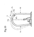
- an engaging portion 6 ⁇ shown in Fig. 10 is so arranged that an upward facing unciform portion 61 ⁇ is arranged at the distal end portion 11a of the first binding member 11 and a downward facing unciform portion 62 ⁇ is arranged at the distal end portion 12a of the second binding member 12 and the first binding member 11 makes an engagement with the second binding member 12 through the upward facing unciform portion 61 ⁇ and the downward facing unciform portion 62 ⁇ by making use of the temporary elastic transformation wherein the distal end portion 11a of the first binding member 11 gets into under the distal end portion 12a of the second binding member 12.
- the file 2 drops on a floor with its top head portion T first and an outward external force to open the closed loop formed with the first and the second binding members 11, 12 acts on the first and the second binding members 11, 12, since the engaging portion 6 ⁇ has an arrangement to engage in the teeth of a direction to open the closed loop, the space between the distal end portions 11a, 12a can be kept closed.
- the second binding member 12 might transform plastically toward a direction to buckle due to a reactive force from the floor or a compressive force from the bound papers or leaves.
- the ups and downs engaging arrangement as shown in Fig.
- the second binding member 12 since the second binding member 12 is prevented from getting into under the first binding member 11, the second binding member 12 can be effectively prevented from plastic transformation.
- the space between the first and the second binging members 11 and 12 can be avoided from opening, thereby to prevent the bound papers or leaves from scattering.
- the file 2 can be made more solid against the outward external force to open the closed loop applied to the first and the second binding members 11, 12.
- the engaging portion 6 ⁇ shown in Fig. 10 has the above-mentioned effect, however, it is hard to say solid against the external force to make the first and the second binding members 11, 12 improperly paired along a longitudinal length of the scroop 33. Then if an engaging arrangement is an engaging portion 6 ⁇ shown in Fig. 11, the engaging portion 6 ⁇ can be made more solid against the external force to open the closed loop applied to the first and the second binding members 11, 12 and the file 2 can be realized that is solid against the external force along a longitudinal length of the scroop 33.
- the engaging portion 6 ⁇ comprises an outward facing unciform portion 61 ⁇ 1 and an upward facing unciform portion 61 ⁇ 2 arranged at the distal end portion 11a of the first binding member 11 and an inward facing unciform portion 62 ⁇ 1 and a downward facing unciform portion 62 ⁇ 2 arranged at the distal end portion 12a of the second binding member 12 wherein the outward facing unciform portion 61 ⁇ 1 hooks against the inward facing unciform portion 62 ⁇ 1 and the upward facing unciform portion 61 ⁇ 2 hooks against the downward facing unciform portion 62 ⁇ 2 so as to engage the first binding member 11 with the second binding member 12 by both a movement of temporary elastic transformations of the first binding members 11 and 11 approaching each other and the second binding members 12 being separated from each other and a movement of temporary elastic transformations of the first binding member 11 getting into relatively under the second binding member 12 are caused simultaneously or around the time.
- an undercut portion 61 ⁇ 1x of the outward facing unciform portion 61 ⁇ 1 and an undercut portion 62 ⁇ 1x of the inward facing unciform portion 62 ⁇ 1 engage each other and an undercut portion 61 ⁇ 2x of the upward facing unciform portion 61 ⁇ 2 and an undercut portion 62 ⁇ 2x of the downward facing unciform portion 62 ⁇ 2 engage each other.
- a space between the distal end portions 11a, 12a can be kept in a closed condition against the external force to open the closed loop applied to the first binding member 11 and the second binding member and the second binding member 12 is prohibited from a movement of getting into under the first binding member 11 by a compressive force, thereby to make the file 2 solid against the external force to make the first and the second binding members 11, 12 improperly paired along a longitudinal direction of the scroop 33.
- the binding member 101 of this embodiment shown in Fig. 12 and Fig. 13 has fundamentally the same arrangement as that of the binding member 1 in accordance with the first embodiment. Same numerals are given to common components and explanation is omitted.
- Shapes of the first and the second binding members 111, 112 of the binding member 101 are different from those of the first and the second binding members 11, 12 constituting the binding member 1 in accordance with the first embodiment.
- the first binding member 111 and the second binding member 112 form a D-shape in a closed state.
- the first binding member 111 comprises a rising area 111x that rises generally vertical to the base 10 in a closed state, a curved area 111y that describes a big moderate curve from a distal end side of the rising area 111x toward the second binding member 112 and an extending area 111z that extends generally parallel to the base 10 from the curved area 111y.
- the second binding member 112 comprises a rising area 112x that rises from the base 10 by a height longer than a height of the rising area 111x and a curved area 112y that describes a curve in a curvature radius far smaller than that of the curbed area 111y from a distal end side of the rising area 112x.
- a closed position locates at a portion constituting a top head portion T of the D-shape where a distal end portion 111a of the first binding member 111 meets a distal end portion 112a of the second binding member 112 facing upward at an angle and generally above the rising area 112x of the second binding member 112.
- the engaging portion 6 comprising unciform portions having the same arrangement as that of the first embodiment is arranged at each of distal end portions 111a and 112a of the first binding member 111 and the second binding member 112.
- Other arrangement of the release means 4 or the operating lever 5 may be the same as that of the first embodiment.
- the top head portion T consists of the extending area 111z extending generally parallel to the base 10 out of the first and the second binding members 111 and 112, as is clear from a comparison between Fig. 2 and Fig. 12, a length from a proximal end portion of the binding member 101 to a distal end portion thereof (same applies to a height) becomes small although a substantial amount to bind papers or leaves is the same when compared with a binding member whose top head portion T is in a shape of an arch.
- the first and the second binding members 111, 112 are difficult to make an elastic transformation, thereby to effectively prevent a case such as a space between the distal end portions 111a, 112a easily opens.
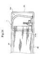
- the top head portion T comprises the extending portion 111z that extends generally parallel to the base 10 and the rising area 112x as the substantial area to bind papers or leaves occupies almost all of the internal dimension between the front cover sheet 31 and the rear cover sheet 32 as shown in Fig. 14, thereby to scarcely form a dead space between the front cover sheet 31 and the rear cover sheet 32 when compared with a binding member whose top head portion T is in a shape of an arch.
- a binding member whose top head portion T is in a shape of an arch.
- each component is not limited to the above-described embodiment.
- the engaging portion may have a shape other than the above-described shape.
- the engaging portion has an arrangement in which the engaged state is released with movements of a pair of the first binding members approaching each other and a pair of the second binding members being separated from each other, however, the engaging portion may have an arrangement in which the engaged state is released with movements of a pair of the first binding members toward the same direction and the second binding members toward the opposite direction.
- the first and the second binding members may make an open and close movement with a rotational movement of each binding members.
- Other arrangement may be various modifications without departing from the spirit of the invention.
- the binding member can be kept in an appropriate bound state and a function of the binding member can be kept unharmed even though the binding member is dropped, it is possible to make effective use of a file that is used with an intention that the file can bind a large amount of papers or leaves or can be used by children or the file can be carried frequently.
- an efficiency of storing can effectively be improved.
Landscapes
- Sheet Holders (AREA)
Abstract
Description
- This invention relates to a binding member and a file comprising an operating lever that can be used preferably in an office or the like.
- For example, as this kind of a binding member well-known is that comprises a pair of first binding members a, a and a pair of second binding members b, b corresponding to the first binding members a, a each of which is mounted on a base e, as shown in Fig. 15, wherein a bound state or a released state of papers or leaves can be realized by closing or opening a space between a distal end portion a1 of the first binding member a and a distal end portion b1 of the corresponding second binding member b through a relatively rotational movement of the first binding member a and the corresponding second binding member b. The binding member A comprises a release means c that applies a force toward a direction to open the space between the distal end portion a1 of the first binding member a and the distal end portion b1 of the corresponding second binding member b and an operating lever d that keeps the distal end portion a1 of the first binding member a and the distal end portion b1 of the corresponding second binding member b at a closed position by relatively rotating the first binding member a and the corresponding second binding member b in the teeth of the release means c.
- The binding member A is so arranged that the first and the second binding members a, b make a relatively rotational movement toward a direction to which a space between the distal end portions a1, b1 is closed in the teeth of a force applied by the release means c with an operation of the operating lever d downward so as to close the space between the distal end portions a1, b1 of the first and the second binding members a, b. Then the distal end portions a1, b1 of the first and the second binding members a, b make an abutting contact each other so that the space closes and the bound state of the papers or leaves can be kept by the first and the second binding members a, b under a keeping force by the operating lever d.
- Meanwhile when the keeping force to keep the distal end portions a1, b1 of the first and the second binding members a, b at a closed position is released with an operation of the operating lever d upward, the first and the second binding members a, b make a relative movement to open the space between the distal end portions a1, b1 so as to make a transition to be in a released state due to a force to open the space between the distal end portions a1, b1 applied to the first and the second binding members a, b by the release means c.
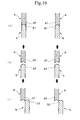
- Each of the distal end portions a1, b1 of the first and the second binding members a, b has a concave-convex arrangement to smoothly fit each other along a direction to open or close as shown in Fig. 16 (a), and makes an abutting engagement each other so as to form an arch shape with the first and the second binding members a, b.
- However, if an external force is accidentally applied to the first or the second binding member a, b due to drops of the binding member A or any other cause, since the distal end portions a1, b1 of the first and the second binding members a, b only make an abutting contact each other along a direction to close the space with a concave-convex engagement, it is very likely to temporarily form a gap between the distal end portions a1, b1 because of an elastic transformation toward a direction to open the space as shown in Fig. 16 (b) or to reclose the space incompletely in an improperly paired condition after the concave-convex engagement is released as shown in Fig. 16 (c) even though the operating lever d is in a closed position. As a result, there might be problems such that the papers or leaves get stuck between the distal end portions a1 b1, the papers or leaves drop out of the binding member A, the operating lever d can not be properly operated to open the space due to the improperly paired condition of the first and the second binding members a, b, or the space is not open due to a plastic transformation of the first or the second binding member a, b when the first and the second binding members a, b are in the improperly paired condition even though the operating lever d can properly be operated.
- Especially, although the first and the second binding members a, b form an arch shape in a state the space is closed, a substantial area to bind the papers or leaves is a rising portion of the second binding member b rising generally vertically from the base e and a top head portion T only serves as an area to pass the papers or leaves at a time to access contents of the papers or leaves or to add or remove papers or leaves. Then a distance between a proximal end portion a2 of the first binding member a to the distal end portion a1 thereof becomes long more than necessary due to the top head portion T, which tends to cause an elastic transformation when an external force is applied to a side of the distal end portions a1 b1, thereby to cause the above-mentioned problems more prominently.
- In addition, if a file F is so arranged that the above-mentioned binding member A is mounted on a cover sheet body B, a dead space D is formed between a front cover sheet B1 and a rear cover sheet B2 as shown in Fig. 17 due to a shape of the top head portion T, thereby to drop an efficiency of storing papers or leaves or to increase an outer shape of the file F unnecessarily.
- In order to solve the above problems the present claimed invention mainly intends to provide a binding member and a file wherein the papers or leaves can be prevented from getting stuck between the binding members or dropping out of the binding member and the operating lever can be properly operated in spite of an external force accidentally applied to circumference of the distal end portions of the first and the second binding members with the first and the second binding members kept in a closed position by the operating lever.
- In order to attain the above object the present claimed invention has a following arrangement.
- A binding member in accordance with the present claimed invention comprises a pair of first binding members and a pair of second binding members corresponding to the first binding members wherein a bound state or a released state of papers or leaves can be realized by closing or opening a space between a distal end portion of the first binding member and a distal end portion of the corresponding second binding member through a relatively rotational movement of the first binding member and the corresponding second binding member, and further comprises a release means that applies a force toward a direction to open the space between the distal end portion of the first binding member and the distal end portion of the corresponding second binding member and an operating lever that keeps the distal end portion of the first binding member and the distal end portion of the corresponding second binding member at a closed position by relatively rotating the first binding member and the corresponding second binding member in the teeth of the release means. In addition, the binding member is characterized by that between the distal end portions arranged is an engaging portion that engages the distal end portions of the first and the corresponding second binding members through a temporary elastic transformation of at least either one of the first binding member and the corresponding second binding member and that prohibits the distal end portions from making a movement to open the space between the distal end portions by engaging the first and the corresponding second binding members further more tightly with making use of the force applied by the release means.
- When the operating lever is operated toward a direction to close the space between the distal end portions of the first and the second binding member, both of the first and the second binding members make a relative rotational movement to a direction to close the space between the distal end portions in the teeth of the force applied by the release means. The engaging portion arranged between the distal end portions makes an engagement through the temporary elastic transformation of at least one of the first and the second binding members and a state in which papers or leaves are bound by the first and the second binding members can be obtained under a keeping force by the operating lever. The engaging portion is so arranged to make an engagement further more tightly by a force applied by the release means and the engaged state can not be released without a temporary elastic transformation of the first or the second binding member. This makes it possible to effectively prevent the first and the second binding members from making a transformation, resulting in closing the first and the second binding members again in the improperly paired condition even though the first and the second binding members are likely to transform elastically toward a direction to open the space between the distal end portions because an external force is accidentally applied to the first or the second binding member due to drops of the binding member or any other cause.
- If the operating lever is operated so as to release the keeping force to keep the space between the distal end portions of the first and the second binding members in a closed position and next the first binding member is elastically transformed temporarily by human, the engaging portion is released from engagement. Since a force toward a direction to open the space between the distal end portions is applied to the first and the second binding members by the release means, the first and the second binding members make a relatively rotational movement toward a direction to open the space between the distal end portions so as to obtain a released state of binding.
- In accordance with this embodiment, it is possible to effectively prevent improper binding or dropping the papers or leaves or no-op of the operating lever by prohibiting the distal end portions of the first and the second binding members from making an elastic transformation toward a direction to open the space between the distal end portions, even though an external force is accidentally applied to the first or the second binding member due to drops of the binding member or any other cause. As a result of this, the binding member is solid against drop or accidental collision and reliability and durability as the binding member can be effectively improved.
- It is preferable that the engaging portion makes an engagement by making use of the temporary elastic transformation of the first binding members or the second binding members toward a direction to which a pair of the first binding members approach each other or a pair of the second binding members approach each other.
- In accordance with the arrangement, the binding members can be elastically transformed toward a direction to approach each other with ease by pinching the first binding members with a finger or the like. As a result of this, it is possible to release a bound state of the first and the second binding members easily with a single hand.
- It is also preferable that the engaging portion makes an engagement by making use of the temporary elastic transformation of the first binding members or the second binding members toward a direction to which the first binding members are separated from each other or the second binding members are separated from each other. In accordance with the arrangement, the binding members can be elastically transformed toward a direction to be separated from each other with ease by separating the second binding members with both hands. As a result of this, it is possible to release a bound state of the first and the second binding members easily with both hands even though the first and the second binding members are given a relatively high rigidity.
- As a concrete arrangement of the engaging portion represented is that comprising an inward facing unciform portion arranged at either one of the first binding member and the second binding member and an outward facing unciform portion arranged at the other binding member.
- In accordance with the arrangement, it is possible to realize the engaging portion that engages smoothly with a closing movement and that engages further more tightly toward a direction to which the space between the distal end portions is open precisely with an easy processing or the like.
- In order to further improve an effect and an operation of the present claimed invention it is preferable that each of the first binding member and the second binding member is so arranged to rise with a proximal end portion thereof mounted on a base and a top head portion extending generally parallel to the base is arranged on at least either one of the first binding member and the second binding member locating at a rising end side in a state the space is closed.
- Since the top head portion extending generally parallel to the base is arranged at the rising side of at lease one of the first and the second binding members, a length from a proximal end portion of the binding member to a distal end portion thereof becomes small although a substantial amount to bind papers or leaves is the same when compared with a binding member whose top head portion is in a shape of an arch. As a result, the first and the second binding members are difficult to make an elastic transformation, thereby to effectively prevent a case such as a space between the distal end portions easily opens.
- In case the file is arranged with the binding member mounted on the cover sheet body, an operation and an effect of the file are fundamentally the same as that of the above-mentioned binding member.
- Especially, if the top head portion comprises the extending portion that extends generally parallel to the base, there is scarcely a dead space between the front cover sheet and the rear cover sheet when compared with a binding member whose top head portion is in a shape of an arch, thereby to effectively prevent a drop in storage efficiency and increasing an outer size of the file unnecessarily.
-
- Fig. 1 is a general perspective view of a principal part showing a file comprising a binding member in accordance with a first embodiment of the present claimed invention.
- Fig. 2 is a magnified front view showing the binding member in accordance with the embodiment.
- Fig. 3 is a magnified left side view showing the binding member in accordance with the embodiment.
- Fig. 4 is a magnified plane view showing the binding member in accordance with the embodiment.
- Fig. 5 is a magnified right side view showing the binding member in accordance with the embodiment.
- Fig. 6 is a functional explanatory view of the embodiment.
- Fig. 7 is an operating instruction view of the embodiment.
- Fig. 8 is an operating instruction view of the embodiment.
- Fig. 9 is an operating instruction view of the embodiment.
- Fig. 10 is a view showing a modified form of the embodiment.
- Fig. 11 is a view showing another modified form of the embodiment.
- Fig. 12 is a magnified front view of a binding member in accordance with a second embodiment of the present claimed invention.
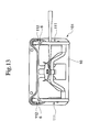
- Fig. 13 is a magnified plane view showing the binding member in accordance with the embodiment.
- Fig. 14 is a functional explanatory view of the embodiment.
- Fig. 15 is a magnified perspective view of a principal part showing a file comprising a conventional binding member.
- Fig. 16 is an explanatory view to explain a conventional problem.
- Fig. 17 is an explanatory view to explain a conventional problem.
- Fig. 1 shows a general perspective view of a principal part showing a
file 2 comprising abinding member 1, each of Fig. 2 through Fig. 5 shows a magnified front view of the bindingmember 1, a magnified left side view thereof, a magnified plane view thereof and a magnified right side view thereof. Thefile 2 comprises acover sheet body 3 having afront cover sheet 31 and arear cover sheet 32 each of which is continuous through ascroop 33 and thebinding member 1 mounted on an inner face of therear cover sheet 32. - The
binding member 1 comprises a pair of first bindingmembers members members base 10 and has an arrangement that a space between adistal end portion 11a of the first bindingmember 11 and adistal end portion 12a of the corresponding secondbinding member 12 is closed or open through a relatively rotational movement of the first bindingmember 11 and the corresponding secondbinding member 12 as shown in Fig. 2. In addition thebinding member 1 further comprises a release means 4 that applies a force toward a direction to open the space between thedistal end portion 11a of the first bindingmember 11 and thedistal end portion 12a of the corresponding second binding member 12 (refer to Fig. 4) and anoperating lever 5 that keeps thedistal end portion 11a and thedistal end portion 12a at a closed position by relatively rotating the first bindingmember 11 and the corresponding second bindingmember 12 in the teeth of the release means 4. - More specifically, the first binding
member 11 and the second bindingmember 12 form an arch-shaped closed loop in a state the space is closed. The first bindingmember 11 comprises a risingarea 11x that rises from thebase 10 in a generally vertical manner and acurved area 11y that curves gently from a distal end side of the risingarea 11x toward the secondbinding member 12 as shown in Fig. 2. The second bindingmember 12 comprises a risingarea 12x that rises from the base 10 by an elevation of a height a litter higher than the risingarea 11x in the state the space is closed and acurved area 12y that curves from a distal end side of the risingarea 12x toward the first bindingmember 11. The closed position of thedistal end portions member 12. - As shown in Fig. 1 and Fig. 4, each of the
distal end portions members portion 13 and arotational axis portion 13a constituting both ends of the connectingportion 13 is rotatably mounted on abearing 10a arranged on thebase 10. A pair of the secondbinding members proximal end portions 12b fixed to thebase 10. A bound state or a released state of papers or leaves can be realized by rotating the first bindingmember 11 with therotational axis portion 13a used as a fulcrum so as to close or open the space between thedistal end portion 11a of the first bindingmember 11 and thedistal end portion 12a of the second bindingmember 12. - The release means 4 has an arrangement that a
crank axle 41 formed to be parallel to therotational axis portion 13a by inflecting a part of the connectingportion 13 of the first bindingmember 11 in a shape of a crank is arranged at a position displaced from therotational axis portion 13a and ablade spring 42 is arranged with itsproximal end edge 42a fixed to thebase 10 and itsdistal end edge 42b elastically making contact with thecrank axle 41 upward from below as shown in Fig. 4. The release means 4 is so arranged that an elastic force is applied to theproximal end portion 11b locating at or near the closed position so as to push the first bindingmember 11 toward a direction to open the space through the connectingportion 13 by making use of an action of theblade spring 42. - The operating
lever 5 comprises, as shown in Fig. 3, arotational arm 51, atransmission portion 52 that is integrally continuous to therotational arm 51 toward a direction generally vertical thereto and an operatingend portion 53 that is arranged to rise on a distal end side of thetransmission portion 52 to be in a reverse L shape. A proximal end of therotational arm 51 is rotatably mounted on a supportingportion 10b arranged to rise on the base 10 through anarm supporting axis 51a parallel to a direction to open or close the first and the secondbinding members roller 54 is mounted on an intersection of therotational arm 51 and thetransmission portion 52 through aroller supporting axis 54a generally parallel to thebase 10. The operatingend portion 53 locates at a position popped upward obliquely in a released position as shown by an imaginary line in Fig. 2 and Fig. 3 and theroller 54 makes a contact with thecrank axel 41 of the connectingportion 13 at a position displaced from a center of thecrank axel 41 in a condition of being able to roll. When the operatingend portion 53 is pushed down from this position, therotational arm 51 makes a rotational movement around thearm supporting axis 51a and theroller 54 moves toward a center portion of the connectingportion 13 with rolling on the connectingportion 13 and pushes the connectingportion 13 downward in the teeth of theblade spring 42. During this period, an elastic force is stored in theblade spring 42 and thedistal end portion 11a of the first bindingmember 11 approaches thedistal end portion 12a of the second bindingmember 12 with rolling so as to finally close the space between thedistal end portions roller 54 moves from a position shown by an imaginary line in Fig. 3 to a position a little higher than the lowest point shown by a solid line in Fig. 3 after passing the lowest point. Since therotational arm 51 is in a condition of generally vertical to thecrank axel 41 of the connectingportion 13, the connectedportion 13 is kept in a pressed condition under the action of toggle even though an operational force to the operatingend portion 53 is removed, and then the bindingmembers portion 13 is received by theblade spring 42. - When the operating
lever 54 is operated upward from this position, theroller 54 is supposed to move on the connectingportion 13 pushed by theblade spring 42 toward a reverse direction from the above and thedistal end portion 11a of the first bindingmember 11 is supposed to be separated from thedistal end potion 12a of the second bindingmember 12 with the first bindingmember 11 rolling backward after theroller 54 passes the lowest point. However, in this embodiment the space between thedistal end portions engaging portion 6 which will be described later. When the operatinglever 5 moves from a state shown by the solid line in Fig. 3 to a state shown by the imaginary line in Fig. 3, the operatinglever 5 is halted at a predetermined position by means of a stopper mechanism, not shown in drawings, arranged between the operatinglever 5 and the base 10 or between near the operatinglever 5 and near thebase 10. - For the binding
member 1 of the above arrangement in this embodiment, between thedistal end portions portion 6 that engages the first and the corresponding second bindingmembers member 11 or the corresponding second bindingmember 12 and that prohibits thedistal end portions distal end portions second binging members - The engaging
portion 6 comprises, as shown in Fig. 5 and Fig. 6 (a) through (c), an outward facingunciform portion 61 in a shape of cutting a part of an outer side of thedistal end portion 11a of the first bindingmember 11 and an inward facingunciform portion 62 in a shape of cutting a part of an inner side of thedistal end portion 12a of the second bindingmember 12. Each of the outward facingunciform portion 61 and the inward facingunciform portion 62 has achevron engaging portion engaging portion chevron engaging portion chevron engaging portion engaging portion chevron engaging portion 61a (62a) of the unciform portion 61 (62) and the valley-shapedengaging portion chevron engaging portions engaging portions - When the
distal end portions binding members chevron engaging portions members second bind members chevron engaging portion 61a (62a) falls in the valley-shapedengaging portion 62b (61b), the engagingportion 6 is formed as shown in Fig. 6 (a) and the first bindingmember 11 and the second bindingmember 12 are made to be a linear body apparently with forming a single continuous loop through the engagingportion 6. Then each of the first bindingmember 11 and the second bindingmember 12 is restored to an original state from an elastically transformed state. - In this embodiment the first and the second
binding members distal end portions distal end portions distal end portions members member 11 and the second bindingmember 12 and to reduce a number of components because there is no need of additional component as a release means. - A
slit 31a is arranged on thefront cover sheet 31 of thecover sheet body 3 at a position corresponding to an arch that is formed when the space between the first and the secondbinding members slit 31a. A projection 31a1 that makes an engagement with an inner periphery of the arch is arranged on an opening edge of theslit 31a. The projection 31a1 and theslit 31a are to maintain a condition that thecover sheet body 3 is closed. - As mentioned above, the binding
member 1 in accordance with the embodiment and thefile 2 on which the bindingmember 1 is mounted are so arranged that the first and the secondbinding members distal end portions lever 5 is operated toward a direction to close the space between thedistal end portions binding members portion 6 that is arranged between thedistal end portions binding members binding members lever 5. - The engaging
portion 6 is so arranged that thechevron engaging portion 61a (62a) and the valley-shapedengaging portion 62b (61b) make an engagement further more tightly by the force applied by the release means 4 toward a direction shown by an arrow in Fig. 6 (a) and the engaged state can not be released without applying a movement of a temporary elastic transformation as shown by an arrow in Fig. 6 (b). This is because each of the undercut portions 61ax and 62ax locating at a basal part of thechevron engaging portion binding members binding members binding members distal end portions member member 1 or any other cause. For example, in a case that thefile 2 drops on a floor with its top head portion T first in a condition that thefront cover sheet 31 and therear cover sheet 32 of thecover sheet body 3 open, the top head portion T receives a reactive force from the floor, or an inertial gravity from the bound papers or leaves acts mainly on the second bindingmember 12 and then an outward external force to open the closed loop formed with the first and the secondbinding members binding members distal end portions potion 6 has an arrangement of making an engagement in the teeth of a force to open the closed loop. In a case that thefile 2 drops with a longitudinal direction of thescroop 33 first, the space between thedistal end portions portion 6 engages itself further more tightly by its movement in either one of the two closed loops each consisting of the first bindingmember 11 and the second bindingmember 12 even though an external force is applied especially to the second bindingmember 12 toward the first bindingmember 11 to make the first and the secondbinding members scroop 33 due to an inertial gravity from the bound papers or leaves acting mainly on the second bindingmember 12. - If the operating
lever 5 is operated as shown by an arrow in Fig. 7 so as to release a keeping force to keep the space between thedistal end portions binding members member portion 6 is released from engagement in sequence of Fig. 6 (a), (b) and (c). Since a force toward a direction to open the space between thedistal end portions binding members binding members distal end portions - As mentioned above, in accordance with this embodiment, it is possible to effectively prevent improper binding or dropping the papers or leaves or no-op of the operating
lever 5 by prohibiting thedistal end portions binding members distal end portions member member 1 or any other cause. As a result of this, the bindingmember 1 can be made solid against drop or accidental collision and reliability and durability as the bindingmember 1 can be effectively improved. - In addition, the engaging
portion 6 is so arranged to make an engagement by making use of a temporary elastic transformation of the first bindingmembers members members binding members - Since the engaging
portion 6 also makes an engagement by making use of a temporary elastic transformation of the secondbinding members binding members binding members binding members binding members - As a concrete arrangement since the engaging
portion 6 has an engaging arrangement in which the outward facingunciform portion 61 makes an engaging with the inward facingunciform portion 62, it is possible to realize the engagingportion 6 that makes a smooth engaging movement when closing and that makes an engagement with each other further more tightly against the force applied toward a direction to which the space between thedistal end portions - In case the
file 2 is arranged with the bindingmember 1 mounted on thecover sheet body 3, an operation and an effect of thefile 2 are fundamentally the same as that of the above-mentionedbinding member 1. - The engaging
portion 6 in accordance with the embodiment has an arrangement in which the outward facingunciform portion 61 is arranged at thedistal end portion 11a of the first bindingmember 11 and the inward facingunciform portion 62 is arranged at thedistal end portion 12a of the second bindingmember 12 and the first bindingmember 11 makes an engagement with the second bindingmember 12 through the outward facingunciform portion 61 and the inward facingunciform portion 62 by making use of the temporary elastic transformation wherein each of the first bindingmembers 11 moves toward a direction to which the first bindingmembers binding members 12 moves toward a direction to which the secondbinding members distal end portion 11a of the first bindingmember 11 and an outward facing unciform portion may be arranged at a side of thedistal end portion 12a of the second bindingmember 12. - A direction of the elastic transformation is not limited to the above as long as the engaging portion makes an engagement through a temporary elastic transformation and the engaging state becomes further more tightly by a force applied by a releasing movement of the release means 4.
- For example, an engaging portion 6α shown in Fig. 10 is so arranged that an upward facing unciform portion 61α is arranged at the
distal end portion 11a of the first bindingmember 11 and a downward facing unciform portion 62α is arranged at thedistal end portion 12a of the second bindingmember 12 and the first bindingmember 11 makes an engagement with the second bindingmember 12 through the upward facing unciform portion 61α and the downward facing unciform portion 62α by making use of the temporary elastic transformation wherein thedistal end portion 11a of the first bindingmember 11 gets into under thedistal end portion 12a of the second bindingmember 12. - For example, even though the
file 2 drops on a floor with its top head portion T first and an outward external force to open the closed loop formed with the first and the secondbinding members binding members distal end portions file 2 drops on a floor with its top head portion T first, the second bindingmember 12 might transform plastically toward a direction to buckle due to a reactive force from the floor or a compressive force from the bound papers or leaves. However, in accordance with the ups and downs engaging arrangement as shown in Fig. 10, since the second bindingmember 12 is prevented from getting into under the first bindingmember 11, the second bindingmember 12 can be effectively prevented from plastic transformation. In addition, even though the second bindingmember 12 might be plastically transformed, the space between the first and thesecond binging members file 2 can be made more solid against the outward external force to open the closed loop applied to the first and the secondbinding members - The engaging portion 6α shown in Fig. 10 has the above-mentioned effect, however, it is hard to say solid against the external force to make the first and the second
binding members scroop 33. Then if an engaging arrangement is an engaging portion 6β shown in Fig. 11, the engaging portion 6β can be made more solid against the external force to open the closed loop applied to the first and the secondbinding members file 2 can be realized that is solid against the external force along a longitudinal length of thescroop 33. - The engaging portion 6β comprises an outward facing unciform portion 61β1 and an upward facing unciform portion 61β2 arranged at the
distal end portion 11a of the first bindingmember 11 and an inward facing unciform portion 62β1 and a downward facing unciform portion 62β2 arranged at thedistal end portion 12a of the second bindingmember 12 wherein the outward facing unciform portion 61β1 hooks against the inward facing unciform portion 62β1 and the upward facing unciform portion 61β2 hooks against the downward facing unciform portion 62β2 so as to engage the first bindingmember 11 with the second bindingmember 12 by both a movement of temporary elastic transformations of the first bindingmembers binding members 12 being separated from each other and a movement of temporary elastic transformations of the first bindingmember 11 getting into relatively under the second bindingmember 12 are caused simultaneously or around the time. In this case also, an undercut portion 61β1x of the outward facing unciform portion 61β1 and an undercut portion 62β1x of the inward facing unciform portion 62β1 engage each other and an undercut portion 61β2x of the upward facing unciform portion 61β2 and an undercut portion 62β2x of the downward facing unciform portion 62β2 engage each other. - In accordance with the arrangement, a space between the
distal end portions member 11 and the second binding member and the second bindingmember 12 is prohibited from a movement of getting into under the first bindingmember 11 by a compressive force, thereby to make thefile 2 solid against the external force to make the first and the secondbinding members scroop 33. As a result, it is possible to prevent the papers or leaves from dropping out so as to main a function as thefile 2 more precisely even through thefile 2 drops on a floor with its top head portion T first or with its longitudinal direction of thescroop 33 along the floor. - The binding
member 101 of this embodiment shown in Fig. 12 and Fig. 13 has fundamentally the same arrangement as that of the bindingmember 1 in accordance with the first embodiment. Same numerals are given to common components and explanation is omitted. - Shapes of the first and the second
binding members member 101 are different from those of the first and the secondbinding members member 1 in accordance with the first embodiment. - The first binding
member 111 and the second bindingmember 112 form a D-shape in a closed state. The first bindingmember 111 comprises a risingarea 111x that rises generally vertical to the base 10 in a closed state, acurved area 111y that describes a big moderate curve from a distal end side of the risingarea 111x toward the second bindingmember 112 and an extendingarea 111z that extends generally parallel to the base 10 from thecurved area 111y. The secondbinding member 112 comprises a risingarea 112x that rises from the base 10 by a height longer than a height of the risingarea 111x and acurved area 112y that describes a curve in a curvature radius far smaller than that of the curbedarea 111y from a distal end side of the risingarea 112x. A closed position locates at a portion constituting a top head portion T of the D-shape where adistal end portion 111a of the first bindingmember 111 meets adistal end portion 112a of the second bindingmember 112 facing upward at an angle and generally above the risingarea 112x of the second bindingmember 112. - The engaging
portion 6 comprising unciform portions having the same arrangement as that of the first embodiment is arranged at each ofdistal end portions member 111 and the second bindingmember 112. Other arrangement of the release means 4 or the operatinglever 5 may be the same as that of the first embodiment. - As mentioned above, since the top head portion T consists of the extending
area 111z extending generally parallel to the base 10 out of the first and the secondbinding members member 101 to a distal end portion thereof (same applies to a height) becomes small although a substantial amount to bind papers or leaves is the same when compared with a binding member whose top head portion T is in a shape of an arch. As a result, the first and the secondbinding members distal end portions - Other arrangement produces the same operation and effect as that of the first embodiment.
- In this embodiment, especially, the top head portion T comprises the extending
portion 111z that extends generally parallel to thebase 10 and the risingarea 112x as the substantial area to bind papers or leaves occupies almost all of the internal dimension between thefront cover sheet 31 and therear cover sheet 32 as shown in Fig. 14, thereby to scarcely form a dead space between thefront cover sheet 31 and therear cover sheet 32 when compared with a binding member whose top head portion T is in a shape of an arch. As a result, it is possible to effectively prevent a drop in storage efficiency and increasing an outer size of the file unnecessarily. - A concrete arrangement of each component is not limited to the above-described embodiment. For example, it is a matter of course that the engaging portion may have a shape other than the above-described shape. In addition, in the above embodiment the engaging portion has an arrangement in which the engaged state is released with movements of a pair of the first binding members approaching each other and a pair of the second binding members being separated from each other, however, the engaging portion may have an arrangement in which the engaged state is released with movements of a pair of the first binding members toward the same direction and the second binding members toward the opposite direction. Further, the first and the second binding members may make an open and close movement with a rotational movement of each binding members. Other arrangement may be various modifications without departing from the spirit of the invention.
- As mentioned above, in accordance with the present claimed invention, since the binding member can be kept in an appropriate bound state and a function of the binding member can be kept unharmed even though the binding member is dropped, it is possible to make effective use of a file that is used with an intention that the file can bind a large amount of papers or leaves or can be used by children or the file can be carried frequently. In addition, in a case that the file is stored in a shelf, an efficiency of storing can effectively be improved.
Claims (10)
- A binding member comprising a pair of first binding members and a pair of second binding members corresponding to the first binding members wherein a bound state or a released state of papers or leaves can be realized by closing or opening a space between a distal end portion of the first binding member and a distal end portion of the corresponding second binding member through a relatively rotational movement of the first binding member and the corresponding second binding member, and further comprising a release means that applies a force toward a direction to open the space between the distal end portion of the first binding member and the distal end portion of the corresponding second binding member and an operating lever that keeps the distal end portion of the first binding member and the distal end portion of the corresponding second binding member at a closed position by relatively rotating the first binding member and the corresponding second binding member in the teeth of the release means, characterized by that between the distal end portions arranged is an engaging portion that engages the distal end portions of the first and the corresponding second binding members through a temporary elastic transformation of at least either one of the first binding member and the corresponding second binding member and that prohibits the distal end portions from making a movement to open the space between the distal end portions by engaging the first and the corresponding second binding members further more tightly with making use of the force applied by the release means.
- The binding member described in claim 1 wherein the engaging portion makes an engagement by making use of the temporary elastic transformation of the first binding members or the second binding members toward a direction to which the first binding members approach each other or the second binding members approach each other.
- The binding member described in claim 1 wherein the engaging portion makes an engagement by making use of the temporary elastic transformation of the first binding members or the second binding members toward a direction to which the first binding members are separated from each other or the second binding members are separated from each other.
- The binding member described in claim 2 or 3 wherein the engaging portion comprises an inward facing unciform portion arranged at either one of the first binding member and the second binding member and an outward facing unciform portion arranged at the other binding member.
- The binding member described in claim 1, 2, 3 or 4
wherein each of the first binding member and the second binding member is so arranged to rise with a proximal end portion thereof mounted on a base and a top head portion extending generally parallel to the base is arranged on at least either one of the first binding member and the second binding member locating at a rising end side in a state the space is closed. - A file having an arrangement that a binding member is mounted on a part of a cover sheet body,
wherein the binding member comprises a pair of first binding members and a pair of second binding members corresponding to the first binding members wherein a bound state or a released state of papers or leaves can be realized by closing or opening a space between a distal end portion of the first binding member and a distal end portion of the corresponding second binding member through a relatively rotational movement of the first binding member and the corresponding second binding member, and further comprising a release means that applies a force toward a direction to open the space between the distal end portion of the first binding member and the distal end portion of the corresponding second binding member and an operating lever that keeps the distal end portion of the first binding member and the distal end portion of the corresponding second binding member at a closed position by relatively rotating the first binding member and the corresponding second binding member in the teeth of the release means, characterized by that between the distal end portions arranged is an engaging portion that engages the distal end portions of the first and the corresponding second binding members through a temporary elastic transformation of at least either one of the first binding member and the corresponding second binding member and that prohibits the distal end portions from making a movement to open the space between the distal end portions by engaging the first and the corresponding second binging members further more tightly with making use of the force applied by the release means. - The file described in claim 6 wherein the engaging portion makes an engagement by making use of the temporary elastic transformation of the first binding members or the second binding members toward a direction to which the first binding members approach each other or the second binding members approach each other.
- The file described in claim 6 wherein the engaging portion makes an engagement by making use of the temporary elastic transformation of the first binding members or the second binding members toward a direction to which the first binding members are separated from each other or the second binding members are separated from each other.
- The file described in claim 7 or 8 wherein the engaging portion comprises an inward facing unciform portion arranged at either one of the first binding member and the second binding member and an outward facing unciform portion arranged at the other binding member.
- The file described in claim 6, 7, 8 or 9 wherein each of the first binding member and the second binding member is so arranged to rise with a proximal end portion thereof mounted on a base and a top head portion extending generally parallel to the base is arranged on at least either one of the first binding member and the second binding member locating at a rising end side in a state the space is closed.
Applications Claiming Priority (1)
| Application Number | Priority Date | Filing Date | Title |
|---|---|---|---|
| PCT/JP2003/013142 WO2005035265A1 (en) | 2003-10-14 | 2003-10-14 | Binder and file |
Publications (2)
| Publication Number | Publication Date |
|---|---|
| EP1674288A1 true EP1674288A1 (en) | 2006-06-28 |
| EP1674288A4 EP1674288A4 (en) | 2008-12-10 |
Family
ID=34430873
Family Applications (1)
| Application Number | Title | Priority Date | Filing Date |
|---|---|---|---|
| EP03754109A Withdrawn EP1674288A4 (en) | 2003-10-14 | 2003-10-14 | Binder and file |
Country Status (5)
| Country | Link |
|---|---|
| EP (1) | EP1674288A4 (en) |
| JP (1) | JPWO2005035265A1 (en) |
| CN (1) | CN1839055A (en) |
| AU (1) | AU2003272996A1 (en) |
| WO (1) | WO2005035265A1 (en) |
Cited By (2)
| Publication number | Priority date | Publication date | Assignee | Title |
|---|---|---|---|---|
| CN101372188B (en) * | 2007-08-23 | 2011-04-20 | 金田克已 | Loose-leaf binder |
| WO2011104305A1 (en) | 2010-02-26 | 2011-09-01 | Biella-Neher Holding Ag | File mechanism |
Families Citing this family (14)
| Publication number | Priority date | Publication date | Assignee | Title |
|---|---|---|---|---|
| US8573876B2 (en) | 2004-03-15 | 2013-11-05 | World Wide Stationery Manufacturing Company, Limited | Soft close ring binder mechanism with mating ring tips |
| US7600939B2 (en) | 2006-09-28 | 2009-10-13 | World Wide Stationery Mfg. Co., Ltd. | Ring binder mechanism with sliding hinge plate |
| EP1942011A1 (en) * | 2007-01-05 | 2008-07-09 | Leco Stationery Manufacturing Co. Ltd. | Lever-arch type file mechanism |
| JP5097977B2 (en) | 2007-09-04 | 2012-12-12 | コクヨ株式会社 | Binding tool, file |
| JP5097978B2 (en) | 2007-09-04 | 2012-12-12 | コクヨ株式会社 | Binding tool, file |
| MX2011000627A (en) * | 2008-07-17 | 2011-02-25 | World Wide Stationery Mfg Co | A paper-retaining mechanism. |
| CN102887010B (en) * | 2008-07-17 | 2015-01-28 | 国际文具制造厂有限公司 | paper holder |
| DE102009005341A1 (en) | 2009-01-16 | 2010-07-22 | Hans Johann Horn | file mechanism |
| CN102039743B (en) * | 2009-10-20 | 2014-11-05 | 美国林.宾德公司 | Clamping ring metal piece |
| CA2742462A1 (en) | 2010-06-09 | 2011-12-09 | World Wide Stationery Manufacturing Co., Ltd. | Ring binder mechanism having unitary structure |
| CN105984250A (en) | 2015-02-05 | 2016-10-05 | 国际文具制造厂有限公司 | Annular binder with interlocking annular members |
| US10479132B2 (en) * | 2015-09-11 | 2019-11-19 | Yugen Kaisha Sankusu | Binding tool and file |
| CN111452535A (en) * | 2019-01-21 | 2020-07-28 | 国誉商业(上海)有限公司 | Loose-leaf binder |
| JP7631813B2 (en) * | 2021-01-12 | 2025-02-19 | コクヨ株式会社 | Ring File |
Family Cites Families (8)
| Publication number | Priority date | Publication date | Assignee | Title |
|---|---|---|---|---|
| DE127784C (en) * | ||||
| FR2221924A5 (en) * | 1973-03-14 | 1974-10-11 | Delka Sa | Ring assembly for loose leaf sheets - has half rings mounted on centre hinged plate with overcentre action |
| JPS60127972U (en) * | 1984-02-07 | 1985-08-28 | 株式会社 キングジム | rotating binding device |
| JPS63198573U (en) * | 1987-06-12 | 1988-12-21 | ||
| US4830528A (en) * | 1988-09-01 | 1989-05-16 | Anthony Handler | Closure mechanism for a loose-leaf holder |
| JP2814957B2 (en) * | 1995-08-09 | 1998-10-27 | コクヨ株式会社 | Ring binding |
| GB2359784A (en) * | 2000-03-01 | 2001-09-05 | Leco Stationery Mfg | Ring binder mechanism held shut by inter-engaging teeth |
| GB0005605D0 (en) * | 2000-03-08 | 2000-05-03 | Leco Stationery Mfg | Device for retaining a stack of papers in a file |
-
2003
- 2003-10-14 WO PCT/JP2003/013142 patent/WO2005035265A1/en not_active Ceased
- 2003-10-14 JP JP2005509477A patent/JPWO2005035265A1/en active Pending
- 2003-10-14 EP EP03754109A patent/EP1674288A4/en not_active Withdrawn
- 2003-10-14 CN CNA200380110478XA patent/CN1839055A/en active Pending
- 2003-10-14 AU AU2003272996A patent/AU2003272996A1/en not_active Abandoned
Cited By (2)
| Publication number | Priority date | Publication date | Assignee | Title |
|---|---|---|---|---|
| CN101372188B (en) * | 2007-08-23 | 2011-04-20 | 金田克已 | Loose-leaf binder |
| WO2011104305A1 (en) | 2010-02-26 | 2011-09-01 | Biella-Neher Holding Ag | File mechanism |
Also Published As
| Publication number | Publication date |
|---|---|
| AU2003272996A1 (en) | 2005-04-27 |
| CN1839055A (en) | 2006-09-27 |
| JPWO2005035265A1 (en) | 2006-12-21 |
| WO2005035265A1 (en) | 2005-04-21 |
| EP1674288A4 (en) | 2008-12-10 |
Similar Documents
| Publication | Publication Date | Title |
|---|---|---|
| US6276862B1 (en) | Binder mechanism | |
| GB2254828A (en) | A lockable ring binder mechanism | |
| US20060065658A1 (en) | Large tough case extension case cover latch | |
| US20040234328A1 (en) | Safety ring binder having sliding actuators | |
| JPWO2005035265A1 (en) | Binding tools and files | |
| CN1402670A (en) | Binder mechanism | |
| US5904435A (en) | Locking booster ring binder mechanism | |
| JPS6285998A (en) | Filing device | |
| EP1129865A2 (en) | Locking mechanism for a lever-arch type file | |
| EP2320105A2 (en) | A cable end retention clip assembly and method for a brake actuating lever | |
| JPH05309986A (en) | Binder for loose-leaf | |
| JP6823281B2 (en) | Ring bindings and ring files | |
| JPH04120085U (en) | binder structure | |
| US9895922B2 (en) | Ring binder with interlocking ring members | |
| JPH05504099A (en) | document punch | |
| JP2009067039A (en) | Binder binding | |
| JP7631813B2 (en) | Ring File | |
| JP2603916Y2 (en) | Binding | |
| EP2186647A1 (en) | Binder, and file | |
| US20090052979A1 (en) | Binding device for files and binders | |
| WO2010024124A1 (en) | Binding device | |
| US20070030331A1 (en) | Releasable device for retaining a finger in the bottom of a notch | |
| JP2528220Y2 (en) | Binder hardware | |
| JP5237771B2 (en) | File | |
| JP3008170U (en) | Clips, clip files using the clips, and scissors for notes |
Legal Events
| Date | Code | Title | Description |
|---|---|---|---|
| PUAI | Public reference made under article 153(3) epc to a published international application that has entered the european phase |
Free format text: ORIGINAL CODE: 0009012 |
|
| 17P | Request for examination filed |
Effective date: 20060301 |
|
| AK | Designated contracting states |
Kind code of ref document: A1 Designated state(s): DE FR GB IT |
|
| RBV | Designated contracting states (corrected) |
Designated state(s): DE FR GB IT |
|
| DAX | Request for extension of the european patent (deleted) | ||
| RBV | Designated contracting states (corrected) |
Designated state(s): DE FR GB IT |
|
| A4 | Supplementary search report drawn up and despatched |
Effective date: 20081106 |
|
| 17Q | First examination report despatched |
Effective date: 20090409 |
|
| STAA | Information on the status of an ep patent application or granted ep patent |
Free format text: STATUS: THE APPLICATION IS DEEMED TO BE WITHDRAWN |
|
| 18D | Application deemed to be withdrawn |
Effective date: 20090820 |
|
| P01 | Opt-out of the competence of the unified patent court (upc) registered |
Effective date: 20230524 |