EP1674282B1 - Kinematic images formed by orienting alignable pigment flakes - Google Patents
Kinematic images formed by orienting alignable pigment flakes Download PDFInfo
- Publication number
- EP1674282B1 EP1674282B1 EP05028190.6A EP05028190A EP1674282B1 EP 1674282 B1 EP1674282 B1 EP 1674282B1 EP 05028190 A EP05028190 A EP 05028190A EP 1674282 B1 EP1674282 B1 EP 1674282B1
- Authority
- EP
- European Patent Office
- Prior art keywords
- image
- flakes
- appears
- bar
- rolling
- Prior art date
- Legal status (The legal status is an assumption and is not a legal conclusion. Google has not performed a legal analysis and makes no representation as to the accuracy of the status listed.)
- Active
Links
- 239000000049 pigment Substances 0.000 title claims description 35
- 238000005096 rolling process Methods 0.000 claims description 88
- 239000000758 substrate Substances 0.000 claims description 32
- 238000000576 coating method Methods 0.000 claims description 9
- 239000011248 coating agent Substances 0.000 claims description 8
- 230000000694 effects Effects 0.000 description 18
- 238000000034 method Methods 0.000 description 17
- 239000000976 ink Substances 0.000 description 15
- 239000003973 paint Substances 0.000 description 15
- 230000003287 optical effect Effects 0.000 description 14
- 230000008569 process Effects 0.000 description 11
- 230000008859 change Effects 0.000 description 10
- 239000007788 liquid Substances 0.000 description 6
- 238000005286 illumination Methods 0.000 description 5
- 238000010422 painting Methods 0.000 description 5
- 239000002245 particle Substances 0.000 description 5
- PXHVJJICTQNCMI-UHFFFAOYSA-N Nickel Chemical compound [Ni] PXHVJJICTQNCMI-UHFFFAOYSA-N 0.000 description 4
- 230000008447 perception Effects 0.000 description 4
- 238000001723 curing Methods 0.000 description 3
- 239000012530 fluid Substances 0.000 description 3
- 239000006249 magnetic particle Substances 0.000 description 3
- 238000001035 drying Methods 0.000 description 2
- 230000005684 electric field Effects 0.000 description 2
- 229910052751 metal Inorganic materials 0.000 description 2
- 239000002184 metal Substances 0.000 description 2
- BASFCYQUMIYNBI-UHFFFAOYSA-N platinum Chemical compound [Pt] BASFCYQUMIYNBI-UHFFFAOYSA-N 0.000 description 2
- 239000010409 thin film Substances 0.000 description 2
- 230000000007 visual effect Effects 0.000 description 2
- 229910000838 Al alloy Inorganic materials 0.000 description 1
- 229910001020 Au alloy Inorganic materials 0.000 description 1
- 229910000990 Ni alloy Inorganic materials 0.000 description 1
- 229910001260 Pt alloy Inorganic materials 0.000 description 1
- 238000003848 UV Light-Curing Methods 0.000 description 1
- 239000006096 absorbing agent Substances 0.000 description 1
- 229910045601 alloy Inorganic materials 0.000 description 1
- 239000000956 alloy Substances 0.000 description 1
- XAGFODPZIPBFFR-UHFFFAOYSA-N aluminium Chemical compound [Al] XAGFODPZIPBFFR-UHFFFAOYSA-N 0.000 description 1
- 239000000969 carrier Substances 0.000 description 1
- 239000003086 colorant Substances 0.000 description 1
- 239000002131 composite material Substances 0.000 description 1
- 238000005034 decoration Methods 0.000 description 1
- 230000007423 decrease Effects 0.000 description 1
- 230000001419 dependent effect Effects 0.000 description 1
- 238000010586 diagram Methods 0.000 description 1
- 230000005672 electromagnetic field Effects 0.000 description 1
- 230000002708 enhancing effect Effects 0.000 description 1
- 238000005562 fading Methods 0.000 description 1
- 239000010408 film Substances 0.000 description 1
- 239000004811 fluoropolymer Substances 0.000 description 1
- 229920002313 fluoropolymer Polymers 0.000 description 1
- 239000011888 foil Substances 0.000 description 1
- PCHJSUWPFVWCPO-UHFFFAOYSA-N gold Chemical compound [Au] PCHJSUWPFVWCPO-UHFFFAOYSA-N 0.000 description 1
- 239000010931 gold Substances 0.000 description 1
- 230000005415 magnetization Effects 0.000 description 1
- 239000000463 material Substances 0.000 description 1
- 239000011159 matrix material Substances 0.000 description 1
- 229910001092 metal group alloy Inorganic materials 0.000 description 1
- 230000003278 mimic effect Effects 0.000 description 1
- 239000000203 mixture Substances 0.000 description 1
- 238000012986 modification Methods 0.000 description 1
- 230000004048 modification Effects 0.000 description 1
- 229910052759 nickel Inorganic materials 0.000 description 1
- 239000002985 plastic film Substances 0.000 description 1
- 229920006255 plastic film Polymers 0.000 description 1
- 230000000630 rising effect Effects 0.000 description 1
- 239000004065 semiconductor Substances 0.000 description 1
- 238000000926 separation method Methods 0.000 description 1
- 239000012798 spherical particle Substances 0.000 description 1
- 238000009987 spinning Methods 0.000 description 1
- 230000003068 static effect Effects 0.000 description 1
- 238000006467 substitution reaction Methods 0.000 description 1
- 230000007704 transition Effects 0.000 description 1
Images


Classifications
-
- G—PHYSICS
- G03—PHOTOGRAPHY; CINEMATOGRAPHY; ANALOGOUS TECHNIQUES USING WAVES OTHER THAN OPTICAL WAVES; ELECTROGRAPHY; HOLOGRAPHY
- G03H—HOLOGRAPHIC PROCESSES OR APPARATUS
- G03H1/00—Holographic processes or apparatus using light, infrared or ultraviolet waves for obtaining holograms or for obtaining an image from them; Details peculiar thereto
- G03H1/04—Processes or apparatus for producing holograms
-
- B—PERFORMING OPERATIONS; TRANSPORTING
- B42—BOOKBINDING; ALBUMS; FILES; SPECIAL PRINTED MATTER
- B42D—BOOKS; BOOK COVERS; LOOSE LEAVES; PRINTED MATTER CHARACTERISED BY IDENTIFICATION OR SECURITY FEATURES; PRINTED MATTER OF SPECIAL FORMAT OR STYLE NOT OTHERWISE PROVIDED FOR; DEVICES FOR USE THEREWITH AND NOT OTHERWISE PROVIDED FOR; MOVABLE-STRIP WRITING OR READING APPARATUS
- B42D25/00—Information-bearing cards or sheet-like structures characterised by identification or security features; Manufacture thereof
- B42D25/30—Identification or security features, e.g. for preventing forgery
- B42D25/36—Identification or security features, e.g. for preventing forgery comprising special materials
- B42D25/369—Magnetised or magnetisable materials
-
- B—PERFORMING OPERATIONS; TRANSPORTING
- B05—SPRAYING OR ATOMISING IN GENERAL; APPLYING FLUENT MATERIALS TO SURFACES, IN GENERAL
- B05D—PROCESSES FOR APPLYING FLUENT MATERIALS TO SURFACES, IN GENERAL
- B05D3/00—Pretreatment of surfaces to which liquids or other fluent materials are to be applied; After-treatment of applied coatings, e.g. intermediate treating of an applied coating preparatory to subsequent applications of liquids or other fluent materials
- B05D3/20—Pretreatment of surfaces to which liquids or other fluent materials are to be applied; After-treatment of applied coatings, e.g. intermediate treating of an applied coating preparatory to subsequent applications of liquids or other fluent materials by magnetic fields
- B05D3/207—Pretreatment of surfaces to which liquids or other fluent materials are to be applied; After-treatment of applied coatings, e.g. intermediate treating of an applied coating preparatory to subsequent applications of liquids or other fluent materials by magnetic fields post-treatment by magnetic fields
-
- B—PERFORMING OPERATIONS; TRANSPORTING
- B05—SPRAYING OR ATOMISING IN GENERAL; APPLYING FLUENT MATERIALS TO SURFACES, IN GENERAL
- B05D—PROCESSES FOR APPLYING FLUENT MATERIALS TO SURFACES, IN GENERAL
- B05D5/00—Processes for applying liquids or other fluent materials to surfaces to obtain special surface effects, finishes or structures
- B05D5/06—Processes for applying liquids or other fluent materials to surfaces to obtain special surface effects, finishes or structures to obtain multicolour or other optical effects
- B05D5/061—Special surface effect
-
- B—PERFORMING OPERATIONS; TRANSPORTING
- B41—PRINTING; LINING MACHINES; TYPEWRITERS; STAMPS
- B41M—PRINTING, DUPLICATING, MARKING, OR COPYING PROCESSES; COLOUR PRINTING
- B41M3/00—Printing processes to produce particular kinds of printed work, e.g. patterns
- B41M3/14—Security printing
- B41M3/148—Transitory images, i.e. images only visible from certain viewing angles
-
- B—PERFORMING OPERATIONS; TRANSPORTING
- B42—BOOKBINDING; ALBUMS; FILES; SPECIAL PRINTED MATTER
- B42D—BOOKS; BOOK COVERS; LOOSE LEAVES; PRINTED MATTER CHARACTERISED BY IDENTIFICATION OR SECURITY FEATURES; PRINTED MATTER OF SPECIAL FORMAT OR STYLE NOT OTHERWISE PROVIDED FOR; DEVICES FOR USE THEREWITH AND NOT OTHERWISE PROVIDED FOR; MOVABLE-STRIP WRITING OR READING APPARATUS
- B42D25/00—Information-bearing cards or sheet-like structures characterised by identification or security features; Manufacture thereof
- B42D25/20—Information-bearing cards or sheet-like structures characterised by identification or security features; Manufacture thereof characterised by a particular use or purpose
- B42D25/29—Securities; Bank notes
-
- B—PERFORMING OPERATIONS; TRANSPORTING
- B42—BOOKBINDING; ALBUMS; FILES; SPECIAL PRINTED MATTER
- B42D—BOOKS; BOOK COVERS; LOOSE LEAVES; PRINTED MATTER CHARACTERISED BY IDENTIFICATION OR SECURITY FEATURES; PRINTED MATTER OF SPECIAL FORMAT OR STYLE NOT OTHERWISE PROVIDED FOR; DEVICES FOR USE THEREWITH AND NOT OTHERWISE PROVIDED FOR; MOVABLE-STRIP WRITING OR READING APPARATUS
- B42D25/00—Information-bearing cards or sheet-like structures characterised by identification or security features; Manufacture thereof
- B42D25/30—Identification or security features, e.g. for preventing forgery
-
- B—PERFORMING OPERATIONS; TRANSPORTING
- B44—DECORATIVE ARTS
- B44F—SPECIAL DESIGNS OR PICTURES
- B44F1/00—Designs or pictures characterised by special or unusual light effects
- B44F1/08—Designs or pictures characterised by special or unusual light effects characterised by colour effects
- B44F1/10—Changing, amusing, or secret pictures
-
- B—PERFORMING OPERATIONS; TRANSPORTING
- B44—DECORATIVE ARTS
- B44F—SPECIAL DESIGNS OR PICTURES
- B44F7/00—Designs imitating three-dimensional effects
-
- G—PHYSICS
- G06—COMPUTING; CALCULATING OR COUNTING
- G06K—GRAPHICAL DATA READING; PRESENTATION OF DATA; RECORD CARRIERS; HANDLING RECORD CARRIERS
- G06K19/00—Record carriers for use with machines and with at least a part designed to carry digital markings
- G06K19/06—Record carriers for use with machines and with at least a part designed to carry digital markings characterised by the kind of the digital marking, e.g. shape, nature, code
- G06K19/08—Record carriers for use with machines and with at least a part designed to carry digital markings characterised by the kind of the digital marking, e.g. shape, nature, code using markings of different kinds or more than one marking of the same kind in the same record carrier, e.g. one marking being sensed by optical and the other by magnetic means
- G06K19/10—Record carriers for use with machines and with at least a part designed to carry digital markings characterised by the kind of the digital marking, e.g. shape, nature, code using markings of different kinds or more than one marking of the same kind in the same record carrier, e.g. one marking being sensed by optical and the other by magnetic means at least one kind of marking being used for authentication, e.g. of credit or identity cards
-
- B—PERFORMING OPERATIONS; TRANSPORTING
- B05—SPRAYING OR ATOMISING IN GENERAL; APPLYING FLUENT MATERIALS TO SURFACES, IN GENERAL
- B05D—PROCESSES FOR APPLYING FLUENT MATERIALS TO SURFACES, IN GENERAL
- B05D7/00—Processes, other than flocking, specially adapted for applying liquids or other fluent materials to particular surfaces or for applying particular liquids or other fluent materials
- B05D7/50—Multilayers
- B05D7/52—Two layers
- B05D7/54—No clear coat specified
- B05D7/546—No clear coat specified each layer being cured, at least partially, separately
-
- B42D2033/18—
-
- Y—GENERAL TAGGING OF NEW TECHNOLOGICAL DEVELOPMENTS; GENERAL TAGGING OF CROSS-SECTIONAL TECHNOLOGIES SPANNING OVER SEVERAL SECTIONS OF THE IPC; TECHNICAL SUBJECTS COVERED BY FORMER USPC CROSS-REFERENCE ART COLLECTIONS [XRACs] AND DIGESTS
- Y10—TECHNICAL SUBJECTS COVERED BY FORMER USPC
- Y10S—TECHNICAL SUBJECTS COVERED BY FORMER USPC CROSS-REFERENCE ART COLLECTIONS [XRACs] AND DIGESTS
- Y10S283/00—Printed matter
- Y10S283/901—Concealed data
-
- Y—GENERAL TAGGING OF NEW TECHNOLOGICAL DEVELOPMENTS; GENERAL TAGGING OF CROSS-SECTIONAL TECHNOLOGIES SPANNING OVER SEVERAL SECTIONS OF THE IPC; TECHNICAL SUBJECTS COVERED BY FORMER USPC CROSS-REFERENCE ART COLLECTIONS [XRACs] AND DIGESTS
- Y10—TECHNICAL SUBJECTS COVERED BY FORMER USPC
- Y10S—TECHNICAL SUBJECTS COVERED BY FORMER USPC CROSS-REFERENCE ART COLLECTIONS [XRACs] AND DIGESTS
- Y10S283/00—Printed matter
- Y10S283/902—Anti-photocopy
-
- Y—GENERAL TAGGING OF NEW TECHNOLOGICAL DEVELOPMENTS; GENERAL TAGGING OF CROSS-SECTIONAL TECHNOLOGIES SPANNING OVER SEVERAL SECTIONS OF THE IPC; TECHNICAL SUBJECTS COVERED BY FORMER USPC CROSS-REFERENCE ART COLLECTIONS [XRACs] AND DIGESTS
- Y10—TECHNICAL SUBJECTS COVERED BY FORMER USPC
- Y10S—TECHNICAL SUBJECTS COVERED BY FORMER USPC CROSS-REFERENCE ART COLLECTIONS [XRACs] AND DIGESTS
- Y10S428/00—Stock material or miscellaneous articles
- Y10S428/90—Magnetic feature
-
- Y—GENERAL TAGGING OF NEW TECHNOLOGICAL DEVELOPMENTS; GENERAL TAGGING OF CROSS-SECTIONAL TECHNOLOGIES SPANNING OVER SEVERAL SECTIONS OF THE IPC; TECHNICAL SUBJECTS COVERED BY FORMER USPC CROSS-REFERENCE ART COLLECTIONS [XRACs] AND DIGESTS
- Y10—TECHNICAL SUBJECTS COVERED BY FORMER USPC
- Y10S—TECHNICAL SUBJECTS COVERED BY FORMER USPC CROSS-REFERENCE ART COLLECTIONS [XRACs] AND DIGESTS
- Y10S428/00—Stock material or miscellaneous articles
- Y10S428/916—Fraud or tamper detecting
-
- Y—GENERAL TAGGING OF NEW TECHNOLOGICAL DEVELOPMENTS; GENERAL TAGGING OF CROSS-SECTIONAL TECHNOLOGIES SPANNING OVER SEVERAL SECTIONS OF THE IPC; TECHNICAL SUBJECTS COVERED BY FORMER USPC CROSS-REFERENCE ART COLLECTIONS [XRACs] AND DIGESTS
- Y10—TECHNICAL SUBJECTS COVERED BY FORMER USPC
- Y10T—TECHNICAL SUBJECTS COVERED BY FORMER US CLASSIFICATION
- Y10T428/00—Stock material or miscellaneous articles
- Y10T428/24—Structurally defined web or sheet [e.g., overall dimension, etc.]
- Y10T428/24802—Discontinuous or differential coating, impregnation or bond [e.g., artwork, printing, retouched photograph, etc.]
-
- Y—GENERAL TAGGING OF NEW TECHNOLOGICAL DEVELOPMENTS; GENERAL TAGGING OF CROSS-SECTIONAL TECHNOLOGIES SPANNING OVER SEVERAL SECTIONS OF THE IPC; TECHNICAL SUBJECTS COVERED BY FORMER USPC CROSS-REFERENCE ART COLLECTIONS [XRACs] AND DIGESTS
- Y10—TECHNICAL SUBJECTS COVERED BY FORMER USPC
- Y10T—TECHNICAL SUBJECTS COVERED BY FORMER US CLASSIFICATION
- Y10T428/00—Stock material or miscellaneous articles
- Y10T428/25—Web or sheet containing structurally defined element or component and including a second component containing structurally defined particles
-
- Y—GENERAL TAGGING OF NEW TECHNOLOGICAL DEVELOPMENTS; GENERAL TAGGING OF CROSS-SECTIONAL TECHNOLOGIES SPANNING OVER SEVERAL SECTIONS OF THE IPC; TECHNICAL SUBJECTS COVERED BY FORMER USPC CROSS-REFERENCE ART COLLECTIONS [XRACs] AND DIGESTS
- Y10—TECHNICAL SUBJECTS COVERED BY FORMER USPC
- Y10T—TECHNICAL SUBJECTS COVERED BY FORMER US CLASSIFICATION
- Y10T428/00—Stock material or miscellaneous articles
- Y10T428/29—Coated or structually defined flake, particle, cell, strand, strand portion, rod, filament, macroscopic fiber or mass thereof
- Y10T428/2982—Particulate matter [e.g., sphere, flake, etc.]
- Y10T428/2991—Coated
Definitions
- This invention relates generally to images with aligned or oriented pigment flakes, for example, during a painting or printing process, to obtain an illusive optical effect.
- This invention is particularly applicable to aligning magnetically alignable pigment flakes and is also applicable to aligning non-magnetic dielectric or semiconductor flakes in an electric field.
- Optically variable devices are used in a wide variety of applications, both decorative and utilitarian. Optically variable devices can be made in variety of ways to achieve a variety of effects. Examples of optically variable devices include the holograms imprinted on credit cards and authentic software documentation, color-shifting images printed on banknotes, and enhancing the surface appearance of items such as motorcycle helmets and wheel covers.
- Optically variable devices can be made as film or foil that is pressed, stamped, glued, or otherwise attached to an object, and can also be made using optically variable pigments.
- One type of optically variable pigment is commonly called a color-shifting pigment because the apparent color of images appropriately printed with such pigments changes as the angle of view and/or illumination is tilted.
- a common example is the "20" printed with color-shifting pigment in the lower right-hand corner of a U.S. twenty-dollar bill, which serves as an anti-counterfeiting device.
- Some anti-counterfeiting devices are covert, while others are intended to be noticed.
- This invention relates to overt features, intended to be noticed, however flakes having covert features therein, such as indicia can be used. Furthermore flakes with gratings and holographic features can be used.
- some optically variable devices that are intended to be noticed are not widely known because the optically variable aspect of the device is not sufficiently dramatic. For example, the color shift of an image printed with color-shifting pigment might not be noticed under uniform fluorescent ceiling lights, but more noticeable in direct sunlight or under single-point illumination. This can make it easier for a counterfeiter to pass counterfeit notes without the optically variable feature because the recipient might not be aware of the optically variable feature, or because the counterfeit note might look substantially similar to the authentic note under certain conditions.
- Optically variable devices can also be made with magnetic pigments that are aligned with a magnetic field after applying the pigment (typically in a carrier such as an ink vehicle or a paint vehicle) to a surface.
- a carrier such as an ink vehicle or a paint vehicle
- painting with magnetic pigments has been used mostly for decorative purposes.
- use of magnetic pigments has been described to produce painted cover wheels having a decorative feature that appears as a three-dimensional shape.
- a pattern was formed on the painted product by applying a magnetic field to the product while the paint medium still was in a liquid state.
- the paint medium had dispersed magnetic non-spherical particles that aligned along the magnetic field lines.
- the field had two regions. The first region contained lines of a magnetic force that were oriented parallel to the surface and arranged in a shape of a desired pattern.
- the second region contained lines that were non-parallel to the surface of the painted product and arranged around the pattern.
- permanent magnets or electromagnets with the shape corresponding to the shape of desired pattern were located underneath the painted product to orient in the magnetic field non-spherical magnetic particles dispersed in the paint while the paint was still wet.
- the pattern was visible on the surface of the painted product as the light rays incident on the paint layer were influenced differently by the oriented magnetic particles.
- the inventors have discovered new and exciting applications of the rolling-bar and other rolling objects such as a rolling hemisphere which yields realistic 3-D like images formed of alignable pigment flakes, not realized before.
- the rolling hemisphere appears to move all directions on an x-y plane in dependence upon an angle at which the image is tilted or the angle at which the light source upon the image varied.
- a rolling bar used as a fill within an outline of a curved recognizable object particularly a smooth curved recognizable object such as a bell, a shield, container, or a soccer ball
- a rolling bar while providing realistic dynamic shading to an image of an object not only appears to move across the image but also appears to grow and shrink or expand and contract with this movement within the closed region in which it is contained.
- this invention provides a highly desired optical effect by using the rolling bar inside a non rectangular outlined closed shape of an object, wherein the area of the rolling bar changes as the bar moves across the image, and, or wherein the bar appears to move horizontally and vertically simultaneously as the image is tilted or the light source upon the image is varied.
- the bar is designed to be of a suitable size and radius of curvature, it can be used as a dynamic, moving, shrinking or expanding shading element in the image, providing exceptional realism. It has also been found, that the rolling bar appears to have a most profound effect when it appears to mimic moving shading on an image of a real object that is capable or producing a shadow when light is incident upon it. In these important applications, it is preferred that the radius of curvature of the flakes forming the rolling bar be within a range of values wherein the image of the real-object it is applied to, appears to be correctly curved so as to appear realistic. It is an object of this invention, to provide an optically illusive image having kinematical features that depend upon tilting the image or varying the location of the light source upon the image.
- rectangular used in this specification is defined to mean a quadrilateral with four right angles. Thus a non-rectangular object or image does not have 4 sides and four right angles.
- This invention refers to forming images of objects wherein the images of the object include special effects such as rolling bar effects that provide the illusion of moving shadows as the image of object is tilted or the light source upon the image is varied.
- objects in this context is a tangible and visible entity; an entity that can cast a shadow.
- rolling bar shall not be limited to a straight bar as it may be a curved bar, depending upon the shape of the applied field.
- the image in accordance with this invention is difficult to counterfeit, visually appealing, easily identifiable and is particularly useful as a security feature or decorative feature.
- the present invention in its various embodiments provides methods of orientation of magnetic flakes of optically variable ink or paint suitable in some embodiments as a high-speed printing process wherein other embodiments are more suited to a manual alignment and printing process.
- some embodiments of this invention require a multi-step printing process wherein a first region of a substrate is inked with magnetic flakes and exposed to a magnetic field, and wherein after curing, the same substrate is inked in a same or different region and exposed to a second magnetic field.
- particles of an optically variable pigment dispersed in a liquid paint or ink vehicle generally orient themselves parallel to the surface when printed or painted on to a surface. Orientation parallel to the surface provides high reflectance of incident light from the coated surface.
- Magnetic flakes can be tilted while in the liquid medium by applying a magnetic field.
- the flakes generally align in such way that the longest diagonal of a flake follows a magnetic field line.
- the magnetic field lines can penetrate the substrate at different angles, tilting magnetic flakes to these angles.
- a tilted flake reflects incident light differently than a flake parallel to the surface of the printed substrate. Reflectance is and a hue can both be different.
- Tilted flakes typically look darker and have a different color than flakes parallel to the surface at a normal viewing angle.
- Orienting magnetic flakes in printed images poses several problems. Many modern printing processes are high-speed relative to the batch-type process that apply a magnet against a static (non-moving) coated article and hold the magnet in position while the paint or ink dries. In some printing presses, the paper substrate is moving at speeds of 100-160 meters per minute. Sheets of paper are stacked after one printing operation, and fed to another. The inks used in such operations typically dry within milliseconds. Convention processes are not suitable for such applications.
- An illusive kinematic optical effect generally provides an illusion of motion in the printed image as the image is tilted relative to the viewing angle, assuming a stationary illumination source.
- Another illusive optical effect provides virtual depth to a printed, two-dimensional image. Some images may provide both motion and virtual depth. And some images may provide the illusion or perception of motion in any direction in an x-y plane.
- Another type of illusive optical effect switched the appearance of a printed field, such as by alternating between bright and dark colors as the image is tilted back and forth.
- Another type of optical effect is created by creating an image wherein a feature of the image appears to change size as the image provides an illusion of motion. Providing a change in size of an object such as a rolling bar as the bar appears to move, provides a form of realistic animation.
- Fig. 1A is a simplified cross sectional view shown in published U.S. patent application 20040051297 published March 18, 2004 of a printed image 29 that will be referred to as a "rolling-bar", for purposes of discussion.
- the image formed of pigment flakes surrounded by a carrier, such as an ink vehicle or a paint vehicle has been aligned in a particular manner of provide the rolling-bar effect.
- the flakes are shown in Fig. 2A as short lines in the cross-sectional view.
- the flakes are magnetic flakes, i.e. pigment flakes that can be aligned using a magnetic field. They might or might not retain remnant magnetization.
- the figures are not drawn to scale.
- a typical flake might be twenty microns across and about one micron thick, hence the figures are merely illustrative.
- the image is printed or painted on a substrate 29, such as paper, plastic film, laminate, card stock, or other surface.
- a substrate such as paper, plastic film, laminate, card stock, or other surface.
- the term "printed” will be used to generally describe the application of pigments in a carrier to a surface, which may include other techniques, including techniques others might refer to as "painting".
- flakes viewed normal to the plane of the flake appear bright, while flakes viewed along the edge of the plane appear dark.
- the carrier is typically transparent, either clear or tinted, and the flakes are typically fairly reflective.
- the carrier could be tinted green and the flakes could include a metallic layer, such as a thin film of aluminum, gold, nickel, platinum, or metal alloy, or be a metal flake, such as a nickel or alloy flake.
- the light reflected off a metal layer through the green-tinted carrier might appear bright green, while another portion with flakes viewed on end might appear dark green or other color. If the flakes are merely metallic flakes in a clear carrier, then one portion of the image might appear bright metallic, while another appears dark.
- the metallic flakes might be coated with a tinted layer, or the flakes might include an optical interference structure, such as an absorber-spacer-reflector Fabry-Perot type structure.
- a diffractive structure may be formed on the reflective surface for providing an enhancement and an additional security feature.
- the diffractive structure may have a simple linear grating formed in the reflective surface, or may have a more complex predetermined pattern that can only be discerned when magnified but having an overall effect when viewing. By providing diffractive reflective layer, a colour change or brightness change is seen by a viewer by simply turning the sheet, banknote, or structure having the diffractive flakes.
- Fig. 2A is a simplified cross section as shown in published U.S. patent application 20040051297 published March 18, 2004 , of a printed image 42 of a kinematic optical "rolling bar".
- the image includes pigment flakes 26 surrounded by a transparent carrier 28 printed on a substrate 29.
- the pigment flakes are aligned in a curving fashion.
- the region(s) of the rolling bar that reflect light off the faces of the pigment flakes to the viewer appear lighter than areas that do not directly reflect the light to the viewer.
- This image provides a light band(s) or bar(s) that appear to move ("roll") across the image when the image is tilted with respect to the viewing angle (assuming a fixed illumination source(s)).
- Fig. 1A is a simplified plan view of the rolling bar image 42 at a first selected viewing angle.
- a bright bar 44 appears in a first position in the image between two contrasting fields 46, 48.
- Fig. 1B is a simplified plan view of the rolling bar image at a second selected viewing angle.
- the bright bar 44' appears to have "moved” to a second position in the image, and the sizes of the contrasting fields 46' , 48' have changed.
- the alignment of the pigment flakes creates the illusion of a bar "rolling" down the image as the image is tilted (at a fixed viewing angle and fixed illumination). Tilting the image in the other direction makes the bar appear to roll in the opposite direction (up).
- the bar may also appear to have depth, even though it is printed in a plane.
- the virtual depth can appear to be much greater than the physical thickness of the printed image.
- the tilting of the flakes in a selected pattern reflects light to provide the illusion of depth or "3D", as it is commonly referred to.
- a three-dimensional effect can be obtained by placing a shaped magnet behind the paper or other substrate with magnetic pigment flakes printed on the substrate in a fluid carrier.
- the flakes align along magnetic field lines and create the 3D image after setting (e.g. drying or curing) the carrier.
- the image often appears to move as it is tilted, hence kinematic 3D images may be formed.
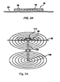
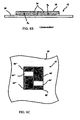
- Fig. 3A is a simplified cross section for forming a semi-circular orientation of flakes in paint or ink for a rolling bar type image.
- a thin permanent magnet 106 is magnetized through its thin section, as illustrated.
- the magnet has circular magnetic lines 108 on its ends.
- the substrate 29 with the printed magnetic flakes dispersed in a fluid carrier moves along the magnet from the viewer into the paper.
- the flakes 26 tilt along direction of the magnetic lines 108 and form a semi-circle pattern above the magnet.
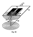
- Fig. 3B is a simplified perspective view of an apparatus in accordance with Fig. 3A .
- the substrate 29 moves across the magnet 106 in the direction of the arrow.
- the image 110 forms a rolling bar feature 114, which will appear to move up and down as the image is tilted or the viewing angle is changed.
- the flakes 26 are shown as being tilted in relation to the magnetic field lines.
- the image is typically very thin, and the flakes might not form a hump, as illustrated, but generally align along the magnetic field lines to provide the desired arched reflective properties to create a rolling bar effect.
- the bar appeared to roll up and down the image when tilted through an angle of about 25 degrees in one example.
- the intensity of the rolling bar effect could be enhanced by chamfering 116 the trailing edge 118 of the magnet. It is believed that this gradually reduces the magnetic field as the image clears the magnet. Otherwise, the magnetic transition occurring at a sharp corner of the magnet might re-arrange the orientation of the flakes and degrade the visual effect of the rolling bar. In a particular embodiment, the corner of the magnet was chamfered at an angle of thirty degrees from the plane of the substrate.
- An alternative approach is to fix the flakes before they pass over the trailing edge of the magnet. This could be done by providing a UV source part way down the run of the magnet, for UV-curing carrier, or a drying source for evaporative carriers, for example.
- FIG. 5A an image in the form of a 4 sided outline or closed region is shown wherein the top side is curved downward. It is interesting to note that upon looking at this figure, there is no particular association with an image made and it is not recognizable as a common object; it is merely a 2-D polygon. On the other hand, upon viewing, Fig. 5B having the same outline and the same flakes but oriented differently an association with a known common recognizable object, a cylinder is made. By providing a large rolling bar that spans the region the rolling bar adds shading so that the user perceives depth and three-dimensionality. In addition to this by tilting the image in Fig.
- Figs. 6 and 7 show rolling bars in two other shapes wherein the rolling bar provides a perception of depth, movement, and wherein the actual area of the bar varies as it sweeps the image.
- a shield comprising an outline having magnetically oriented pigment flakes disposed therein, oriented in the form of a rolling bar having a large radius of curvature. It is important to select a radius of curvature that will provide an expected sense of depth and curvature to most closely represent the image that is created.
- the presence of a rolling bar provides a perceived change in area of the rolling bar as the image is tilted and the bar appears to move across the image. This phenomenon is quite striking and is illustrated by the sequence of figures 14A through 14D . These figures are of the same image tilted at different angles, with an increasing angle in each subsequent figure with Fig. 14A being at normal incidence.
- a circle is shown having a rolling bar spanning its diameter.
- the circle in the absence of the rolling bar is merely what the viewer perceives as a circle, however the presence of the rolling bar provides the viewer with the illusion that the object is a sphere.
- movement is not shown in the figure, the viewer witnessing the bar rolling along the circle apparently becoming smaller as the image is tilted and the bar moves toward the left, give the viewer a sense of three dimensionality and realism.
- this kinematical image provides the viewer with the experience of the light and shadows moving across the ball as the image is tilted.
- the view has the perception of moving around the object or the viewed object being rotated.
- the viewer since the area of the bar decreases as it moves to the left the viewer has the perception that this object is more than just a picture or photograph. It is for all intents and purposes a flat image however the viewer perceives depth and movement and an enhanced viewing experience in contrast to viewing a "normal" image. It has three dimensionality, movement and change of shape that occurs when viewing and tilting the object.
- Fig. 7 the area of the rolling bar shown by highlights in the centre fading off to dark regions toward the sides, as it appears to sweep across the image has a substantially uniform area, however, the bar appears to follow the curved trajectory of the upper and lower walls as it fills the outline and appears to project out of the page, moving from a lower central position to an upper right most or left most position as it rises.
- Fig. 8A an alternative embodiment of the invention is shown wherein two rolling bars are designed to move oppositely simultaneously when the image is tiled in one direction; for example toward the right pointing arrow, about a longitudinal axis of one of the rolling bars.
- FIGs. 8B and 8C an image with a "double rolling bar” is shown, wherein one portion 44' has magnetic flakes oriented in convex fashion while another portion 44"of the image has magnetic flakes oriented in a concave orientation.
- the "rolling bar” magnet is placed underneath the paper substrate.
- the magnet is placed above the paper substrate.
- a "Double tilt" image is formed when magnetic flakes in two regions of the image have differing and opposing orientation, for example, +30 degrees and -30 degrees. At one tilted position of the printed image one part of the image is dark and another part is light.
- the areas switch their light and dark regions so that the first image becomes light and the second image becomes dark.
- this switch of the light and dark may occur from the top to the bottom and back, as well as from the left to the right and back, in dependence upon the on orientation of the flakes.
- the bright bar 44' appears to have "moved” to a second position in the image, and the sizes of the contrasting fields 46', 48' have changed; furthermore the bright bar 44" appears to have "moved” to a different position in the image, and the sizes of the contrasting fields 46", 48" have changed.
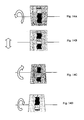
- Figs. 15B through 15D the "liberty bell" is shown.
- Fig. 15A the image is shown at a normal angle of incidence.
- Figs 15B through 15D the same print is shown tiled at different angles of incidence as indicated by arrows about the axis.
- the rolling bar 150 shown if Fig. 15B having a large radius of curvature appears to shift to the left when viewing Fig. 15C , and the smaller concave inverted rolling bar 152 on the inside surface of the bell, appears to move oppositely, to the left.
- Fig. 15B having a large radius of curvature appears to shift to the left when viewing Fig. 15C
- the smaller concave inverted rolling bar 152 on the inside surface of the bell appears to move oppositely, to the left.
- 15D illustrates an opposite perceived movement, wherein the larger bar 150 when tilted oppositely shows the large bar 150 appearing to shift to the right while the smaller bar 152 simultaneously appears to roll to the left.
- This behaviour of the light incident upon the image mimics a real lighting situation on a real object such as the liberty bell. The lighting shifts simultaneously and oppositely in different regions as one would expect from a real object.
- the illusion is designed to follow the physics of natural light on the real object.
- the illusion is that the image is real. Turning now to Fig.
- the four elements 154a, 154b, 154c, and 154d, that comprise the bell are shown separately, for ease of understanding, and each of these is printed, one at a time, in the correct location upon the substrate to form the image shown in Fig. 15A .
- the image is formed by printing each region and applying the magnets to form flakes aligned in oppositely arching patterns to create the two rolling bars, a sequenced automated printed process could be used to produce this and similar images.
- Fig. 16F is a printed image of a hemisphere wherein the entire image is coated with alignable pigment flakes. After alignment of flakes as will be explained, the hemisphere is formed.
- the printed image of the hemisphere shown in Fig. 16F appears as the image shown in Fig. 16G as the substrate is tilted or the light source varied. As the image is tilted from the normal to the left about a vertical axis through the centre, the bright hemisphere which appears much like a ball, rolls with a change of tilt angle.
- the hemisphere in Fig. 16F is capable or appearing to move in any x-y direction, depending upon the angle of tilt.
- tilting the image about the x or y axis results in the appearance of movement.
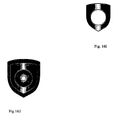
- the shield in Fig. 16J uses a combination of a rolling bar and hemisphere effects to provide very interesting combination of effects wherein the shield and hemisphere appear to project out of the page.
- This is produced in a two stage process, wherein the substrate is first coated with a magnetic coating and a hemisphere is formed and cured as in Fig. 16H .
- a second coating is applied through a mask or stencil to form the coating of Fig. 16I ensuring that no additional coating material covers the hemisphere.
- This second coating is placed in a magnetic field so as to produce a rolling bar.
- the method of forming the dynamic or kinematic hemispherical image described above is more complex than the method of forming the rolling bar.
- the magnet 160a shown in Fig. 16A illustrates a field line above and below the magnet, forming two loops.
- This diagram purposely only shows these two lines, however, there is essentially a front of lines that would be generated parallel to these lines, spanning the entire magnet.
- the magnets 160a, 160b used to create the hemisphere are more complex as is shown in Fig. 16B and more particularly in 16C. Part of the magnet in Fig. 16B is cut away to illustrate some of the field lines.
- the field extending above the cluster of magnets 160a, 160b, 160c is dome shaped, as is the magnetic field extending below.
- a print of a hemispherical kinematic image is formed as in Fig. 16D or 16E by disposing the coated substrate 167 with fluid ink in the dome shaped magnetic field, just above the magnets as shown in Fig. 16D or with greater separation from the magnets and supported toward the middle of the field while the magnets are spinning.
- the velocity at which the magnets or image are relatively rotated is approximately 120 rpm.
- the image is then removed from the region of the field and is cured.
- the rotation velocity of the magnets can be slower or faster than 120 rpm, depending on the particles magnetic properties and viscosity of the ink vehicle. If the velocity is too slow however, the quality of the image will degrade.
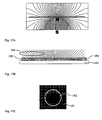
- Fig. 17A is an illustration of an alternative embodiment similar but inverted to the image shown in Fig. 16F .
- a simulated magnetic field from a hemispherical magnet is shown in Fig. 17A .
- This is the shape of the field that created the image shown in Fig. 17C .
- the North pole of the magnet is on the top and the particles are aligned concentrically in a funnel-like fashion.
- the field 194 in Fig. 17B is shown and flakes 193 in a carrier 192 disposed upon substrate 191 are aligned in a funnel like orientation following the field lines.
- this field generated a bright kinematic spot 192 in the middle of the image 191; and the funnel-like alignment of flakes generated a dark kinematic spot in the middle of the image.
- the fields shown and described are formed from permanent magnets, electric fields or electromagnetic fields can be used in many embodiments.
- the field and the particles must be compatible so that the particles are capable of being oriented by the particular field.
Landscapes
- Business, Economics & Management (AREA)
- Accounting & Taxation (AREA)
- Finance (AREA)
- Physics & Mathematics (AREA)
- General Physics & Mathematics (AREA)
- Engineering & Computer Science (AREA)
- Theoretical Computer Science (AREA)
- Printing Methods (AREA)
- Toys (AREA)
- Credit Cards Or The Like (AREA)
- Inks, Pencil-Leads, Or Crayons (AREA)
Description
- This invention relates generally to images with aligned or oriented pigment flakes, for example, during a painting or printing process, to obtain an illusive optical effect. This invention is particularly applicable to aligning magnetically alignable pigment flakes and is also applicable to aligning non-magnetic dielectric or semiconductor flakes in an electric field.
- Optically variable devices are used in a wide variety of applications, both decorative and utilitarian. Optically variable devices can be made in variety of ways to achieve a variety of effects. Examples of optically variable devices include the holograms imprinted on credit cards and authentic software documentation, color-shifting images printed on banknotes, and enhancing the surface appearance of items such as motorcycle helmets and wheel covers.
- Optically variable devices can be made as film or foil that is pressed, stamped, glued, or otherwise attached to an object, and can also be made using optically variable pigments. One type of optically variable pigment is commonly called a color-shifting pigment because the apparent color of images appropriately printed with such pigments changes as the angle of view and/or illumination is tilted. A common example is the "20" printed with color-shifting pigment in the lower right-hand corner of a U.S. twenty-dollar bill, which serves as an anti-counterfeiting device.
- Some anti-counterfeiting devices are covert, while others are intended to be noticed. This invention relates to overt features, intended to be noticed, however flakes having covert features therein, such as indicia can be used. Furthermore flakes with gratings and holographic features can be used. Unfortunately, some optically variable devices that are intended to be noticed are not widely known because the optically variable aspect of the device is not sufficiently dramatic. For example, the color shift of an image printed with color-shifting pigment might not be noticed under uniform fluorescent ceiling lights, but more noticeable in direct sunlight or under single-point illumination. This can make it easier for a counterfeiter to pass counterfeit notes without the optically variable feature because the recipient might not be aware of the optically variable feature, or because the counterfeit note might look substantially similar to the authentic note under certain conditions.
- Optically variable devices can also be made with magnetic pigments that are aligned with a magnetic field after applying the pigment (typically in a carrier such as an ink vehicle or a paint vehicle) to a surface. However, painting with magnetic pigments has been used mostly for decorative purposes. For example, use of magnetic pigments has been described to produce painted cover wheels having a decorative feature that appears as a three-dimensional shape. A pattern was formed on the painted product by applying a magnetic field to the product while the paint medium still was in a liquid state. The paint medium had dispersed magnetic non-spherical particles that aligned along the magnetic field lines. The field had two regions. The first region contained lines of a magnetic force that were oriented parallel to the surface and arranged in a shape of a desired pattern. The second region contained lines that were non-parallel to the surface of the painted product and arranged around the pattern. To form the pattern, permanent magnets or electromagnets with the shape corresponding to the shape of desired pattern were located underneath the painted product to orient in the magnetic field non-spherical magnetic particles dispersed in the paint while the paint was still wet. When the paint dried, the pattern was visible on the surface of the painted product as the light rays incident on the paint layer were influenced differently by the oriented magnetic particles.
- Similarly, a process for producing of a pattern of flaked magnetic particles in fluoropolymer matrix has been described. After coating a product with a composition in liquid form, a magnet with desirable shape was placed on the underside of the substrate. Magnetic flakes dispersed in a liquid organic medium orient themselves parallel to the magnetic field lines, tilting from the original planar orientation. This tilt varied from perpendicular to the surface of a substrate to the original orientation, which included flakes essentially parallel to the surface of the product. The planar oriented flakes reflected incident light back to the viewer, while the reoriented flakes did not, providing the appearance of a three dimensional pattern in the coating.
- It is desirable to create more noticeable optically variable security features on financial documents and other products and to provide features that are difficult for counterfeiters to copy.
- It is also desirable to create features which add to the realism of printed images made with inks and paints having alignable flakes therein, especially printed images of objects and more particularly recognizable three dimensional objects.
- Heretofore, in patent application
PCT/US2003/020665 , published asWO-A-2004007095 , the inventor of the present application has described embodiments of an invention known as the "rolling-bar" and the "flip-flop" which provide kinematical features, that is features which provide the optical illusion of movement, to images comprised of magnetically alignable pigment flakes wherein the flakes are aligned in a particular manner. Although this is heralded as a significant advance in the field of alignment of pigment flakes, and more generally related to anti-counterfeiting coatings, the inventors have discovered new and exciting applications of the rolling-bar and other rolling objects such as a rolling hemisphere which yields realistic 3-D like images formed of alignable pigment flakes, not realized before. The rolling hemisphere appears to move all directions on an x-y plane in dependence upon an angle at which the image is tilted or the angle at which the light source upon the image varied. - Although the rolling bar described in the aforementioned PCT patent application provides the illusion of a moving bar across a rectangular image, this invention has limitations. It is a single kinematic feature which can be observed. It is also somewhat difficult to copy. But essentially it provides the observer with the experience of seeing a rolling bar of uniform size and intensity which is unvarying as it appears to move along the substrate upon the rectangular image it is apart of.
- In this invention, the inventors have since discovered that providing a rolling bar used as a fill within an outline of a curved recognizable object, particularly a smooth curved recognizable object such as a bell, a shield, container, or a soccer ball provides striking effects that reach beyond a rolling bar moving back and forth on a rectangular sheet. The bar while providing realistic dynamic shading to an image of an object not only appears to move across the image but also appears to grow and shrink or expand and contract with this movement within the closed region in which it is contained. In some instances where the size or area of the bar doesn't vary, for example wherein it is used a as a partial fill within an image between two conforming curved lines that move together with a space between, filled by the bar, the bar appears to move across the image while simultaneously moving up and down. Thus, this invention provides a highly desired optical effect by using the rolling bar inside a non rectangular outlined closed shape of an object, wherein the area of the rolling bar changes as the bar moves across the image, and, or wherein the bar appears to move horizontally and vertically simultaneously as the image is tilted or the light source upon the image is varied. Additionally, if the bar is designed to be of a suitable size and radius of curvature, it can be used as a dynamic, moving, shrinking or expanding shading element in the image, providing exceptional realism. It has also been found, that the rolling bar appears to have a most profound effect when it appears to mimic moving shading on an image of a real object that is capable or producing a shadow when light is incident upon it. In these important applications, it is preferred that the radius of curvature of the flakes forming the rolling bar be within a range of values wherein the image of the real-object it is applied to, appears to be correctly curved so as to appear realistic. It is an object of this invention, to provide an optically illusive image having kinematical features that depend upon tilting the image or varying the location of the light source upon the image.
- The term rectangular used in this specification is defined to mean a quadrilateral with four right angles. Thus a non-rectangular object or image does not have 4 sides and four right angles.
- This invention refers to forming images of objects wherein the images of the object include special effects such as rolling bar effects that provide the illusion of moving shadows as the image of object is tilted or the light source upon the image is varied. The definition of object in this context is a tangible and visible entity; an entity that can cast a shadow.
- The term rolling bar shall not be limited to a straight bar as it may be a curved bar, depending upon the shape of the applied field.
- According to the present invention, an image on a substrate as defined in claim 1 is provided. The dependent claims defined preferred or advantageous embodiments of the invention.
- The image in accordance with this invention is difficult to counterfeit, visually appealing, easily identifiable and is particularly useful as a security feature or decorative feature.
- Exemplary embodiments of the invention will now be described in accordance with the figures. Since the figures shown in this application represent the images in accordance with this invention, made with magnetic flakes, these effects cannot be provided in this document which attempts to describe and illustrate these kinematical and 3-D features.
-
Fig. 1A is a simplified plan view of the rolling bar image at a first selected viewing angle. -
Fig. 1B is a simplified plan view of the rolling bar image at a second selected viewing angle. -
Fig. 2A is a simplified cross section of a printed image that will be referred to as a "rolling bar" for purposes of discussion, according to another embodiment of the present invention. -
Fig.3A is a simplified cross section of another embodiment of the invention for forming a semi-circular orientation of flakes in paint or ink for a rolling bar type image. -
Fig. 3B is a simplified perspective view of apparatus in accordance withFig. 3A . -
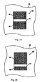
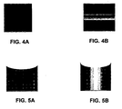
Fig. 4A is a plan view of an image comprised of non-aligned magnetic pigment flakes cured on a substrate. -
Fig. 4B is a plan view of the flakes and substrate shown inFig. 4A after the flakes have been aligned and permanently fixed by curing the pigment so as to orient them into a rolling bar similar toFigs 1A and 1B . -
Fig. 5A is a plan view of an image having a curved upper contour comprised of non-aligned magnetic pigment flakes. -
Fig. 5B is a plan view of the image similar toFig. 5A with the flakes aligned into a large rolling bar, with a substantially large radius of curvature. -
Fig. 6 is a partial perspective view of an image of a sphere wherein an outline of a circle has a rolling bar spanning its diameter providing the illusion of a sphere. The embodiment shown inFig. 6 does not form a part of the invention. -
Fig. 7 is a shape similar toFig. 5B wherein both upper and lower surfaces are curved. The embodiment shown inFig. 7 does not form a part of the invention. -
Fig. 8A is an image in perspective view of container, having a rolling bar applied to an outer front wall, and another rolling bar on the inner back wall, wherein the two rolling bars move in opposite directions simultaneously as the image is tilted in the direction of one of the arrows. -
Fig. 8B , shown on a separate sheet fromFig. 8A , is a cross-sectional view of two rolling bars shown inFig. 8C . -
Fig. 8C is a plan view of a more simple arrangement of two rolling bars which move oppositely, simultaneously, as the image is tilted. The embodiment shown inFig. 8C does not form a part of the invention -
Fig. 9 is a perspective view of an image of a container similar to the one shown inFig. 8A wherein rolling bars are shown on adjacent outside inside faces, wherein the rolling bars move oppositely and wherein the rolling bar on the inner face changes area and shape as it is perceived to move upon tilting. -
Fig. 10 is an image of a sphere having two rolling elongate shapes shown which provide a 3-D realistic quality to the image as the image it tilted. -
Fig. 11 is an image of a cylinder having rolling bar on an outer front-facing surface of the cylinder. The embodiment shown inFig. 11 does not form a part of the invention. -
Fig. 12 is an image of a shield wherein the rolling bar provides a kinematic effect and wherein the bar provides shading and depth adding realism to the image not attainable in a photograph or painting. The embodiment shown inFig. 12 does not form a part of the invention -
Fig. 13 is an image of a hollow cylinder or pipe with a double (concave and convex) rolling bar, wherein the concave rolling bar is shown on the inside wall, and wherein the two rolling bars move oppositely as shadows and light in the real object would move.. -
Figs 14A through 14D are views of a curved image having a rolling bar shown at four different viewing angles. The embodiment shown inFigs. 14A through 14D does not form a part of the invention. -
Fig. 15A is illustrates four components of the liberty bell printed on a rectangular substrate. Inner part of the bell is printed with the concave rolling bar and the outer part of the bell is printed with the convex rolling bar. -
Fig. 15B is a drawing of an image of the liberty bell at normal angle. -
Fig. 15C shows the bell when the substrate is tilted to the right -
Fig. 15D shows the bell when the substrate is tilted to the left. -
Fig. 16A is a perspective view of a magnet which makes up a magnetic configuration shown inFig. 16C for providing a dome shaped magnetic field as shown inFig. 16C . -
Fig. 16B is a perspective view having some magnets cut-away for ease of viewing for providing a dome-shaped field. -
Fig. 16C is a perspective view of a magnetic arrangement for providing dome-shaped magnetic field. -
Fig. 16D is a perspective view of the magnetic arrangement ofFig. 16C wherein sheet having flaked ink applied thereto is disposed in the dome-shaped field and wherein the sheet and field are relatively rotated indicated by the arrows in the subsequent two figures. -
Fig. 16E is a perspective view similar to that ofFig. 16D , wherein the sheet is disposed closer to the top of the dome-shaped field and wherein a hemispherical image formed in the ink would be smaller in size than inFig. 16D . -
Fig. 16F and 16G are images of the rolling 3-D hemisphere made using the magnets ofFig. 16E shown at different positions as the image is tilted from one position to another. -
Fig. 16H is a printed image of a hemisphere having dome shaped flakes disposed in an image of a shield. -
Fig. 16I is a printed image of a shield having a rolling bar formed along an axis thereof. -
Fig 16J is a composite image of the images formed inFig. 16H and16I , wherein the ink and magnetic fields are applied in stages so thatFig. 16I is applied overFig. 16H and wherein the centre region is coated only once, when forming the rolling hemisphere. -
Fig. 17A is a cross-section of a bowl shaped field used to form the image ofFig. 17C . -
Fig. 17B is cross-sectional of pigment flakes in a carrier aligned in the magnetic field shown inFig. 17A . -
Fig. 17C is an image formed with magnetic flakes in the field shown inFig. 17A of an inverted hemisphere which appears to be a rolling bowl sunken into the page. - The present invention in its various embodiments provides methods of orientation of magnetic flakes of optically variable ink or paint suitable in some embodiments as a high-speed printing process wherein other embodiments are more suited to a manual alignment and printing process. In addition, some embodiments of this invention require a multi-step printing process wherein a first region of a substrate is inked with magnetic flakes and exposed to a magnetic field, and wherein after curing, the same substrate is inked in a same or different region and exposed to a second magnetic field. Normally, particles of an optically variable pigment dispersed in a liquid paint or ink vehicle generally orient themselves parallel to the surface when printed or painted on to a surface. Orientation parallel to the surface provides high reflectance of incident light from the coated surface. Magnetic flakes can be tilted while in the liquid medium by applying a magnetic field. The flakes generally align in such way that the longest diagonal of a flake follows a magnetic field line. Depending on the position and strength of the magnet, the magnetic field lines can penetrate the substrate at different angles, tilting magnetic flakes to these angles. A tilted flake reflects incident light differently than a flake parallel to the surface of the printed substrate. Reflectance is and a hue can both be different. Tilted flakes typically look darker and have a different color than flakes parallel to the surface at a normal viewing angle.
- Orienting magnetic flakes in printed images poses several problems. Many modern printing processes are high-speed relative to the batch-type process that apply a magnet against a static (non-moving) coated article and hold the magnet in position while the paint or ink dries. In some printing presses, the paper substrate is moving at speeds of 100-160 meters per minute. Sheets of paper are stacked after one printing operation, and fed to another. The inks used in such operations typically dry within milliseconds. Convention processes are not suitable for such applications.
- It was discovered that one way to obtain enhanced optical effects in the painted/printed image, is by orienting magnetic flakes perpendicular to the direction of the moving substrate. In other words, the painted or printed liquid paint or ink medium with dispersed flakes on the substrate moves perpendicular to magnetic lines of the field to cause re-orientation of the flakes. This type of orientation can provide remarkable illusive optical effects in the printed image.
- One type of optical effect will be referred to as a kinematic optical effect for purposes of discussion. An illusive kinematic optical effect generally provides an illusion of motion in the printed image as the image is tilted relative to the viewing angle, assuming a stationary illumination source. Another illusive optical effect provides virtual depth to a printed, two-dimensional image. Some images may provide both motion and virtual depth. And some images may provide the illusion or perception of motion in any direction in an x-y plane. Another type of illusive optical effect switched the appearance of a printed field, such as by alternating between bright and dark colors as the image is tilted back and forth. Another type of optical effect is created by creating an image wherein a feature of the image appears to change size as the image provides an illusion of motion. Providing a change in size of an object such as a rolling bar as the bar appears to move, provides a form of realistic animation.
-
Fig. 1A is a simplified cross sectional view shown in publishedU.S. patent application 20040051297 published March 18, 2004 of a printedimage 29 that will be referred to as a "rolling-bar", for purposes of discussion. The image formed of pigment flakes surrounded by a carrier, such as an ink vehicle or a paint vehicle has been aligned in a particular manner of provide the rolling-bar effect. The flakes are shown inFig. 2A as short lines in the cross-sectional view. The flakes are magnetic flakes, i.e. pigment flakes that can be aligned using a magnetic field. They might or might not retain remnant magnetization. The figures are not drawn to scale. A typical flake might be twenty microns across and about one micron thick, hence the figures are merely illustrative. The image is printed or painted on asubstrate 29, such as paper, plastic film, laminate, card stock, or other surface. For convenience of discussion, the term "printed" will be used to generally describe the application of pigments in a carrier to a surface, which may include other techniques, including techniques others might refer to as "painting". - Generally, flakes viewed normal to the plane of the flake appear bright, while flakes viewed along the edge of the plane appear dark.
- The carrier is typically transparent, either clear or tinted, and the flakes are typically fairly reflective. For example, the carrier could be tinted green and the flakes could include a metallic layer, such as a thin film of aluminum, gold, nickel, platinum, or metal alloy, or be a metal flake, such as a nickel or alloy flake. The light reflected off a metal layer through the green-tinted carrier might appear bright green, while another portion with flakes viewed on end might appear dark green or other color. If the flakes are merely metallic flakes in a clear carrier, then one portion of the image might appear bright metallic, while another appears dark. Alternatively, the metallic flakes might be coated with a tinted layer, or the flakes might include an optical interference structure, such as an absorber-spacer-reflector Fabry-Perot type structure. Furthermore, a diffractive structure may be formed on the reflective surface for providing an enhancement and an additional security feature. The diffractive structure may have a simple linear grating formed in the reflective surface, or may have a more complex predetermined pattern that can only be discerned when magnified but having an overall effect when viewing. By providing diffractive reflective layer, a colour change or brightness change is seen by a viewer by simply turning the sheet, banknote, or structure having the diffractive flakes.
- The process of fabricating diffractive flakes is described in detail in United States patent number
6692830 .US patent application 20030190473 , describes fabricating chromatic diffractive flakes. Producing a magnetic diffractive flake is similar to producing a diffractive flake, however one of the layers is required to be magnetic. In fact, the magnetic layer can be disguised by way of being sandwiched between Al layers; in this manner the magnetic layer and then it doesn't substantially affect the optical design of the flake; or could simultaneously play an optically active role as absorber, dielectric or reflector in a thin film interference optical design. -
Fig. 2A is a simplified cross section as shown in publishedU.S. patent application 20040051297 published March 18, 2004 , of a printedimage 42 of a kinematic optical "rolling bar". The image includespigment flakes 26 surrounded by atransparent carrier 28 printed on asubstrate 29. The pigment flakes are aligned in a curving fashion. As with the flip-flop, the region(s) of the rolling bar that reflect light off the faces of the pigment flakes to the viewer appear lighter than areas that do not directly reflect the light to the viewer. This image provides a light band(s) or bar(s) that appear to move ("roll") across the image when the image is tilted with respect to the viewing angle (assuming a fixed illumination source(s)). -
Fig. 1A is a simplified plan view of the rollingbar image 42 at a first selected viewing angle. Abright bar 44 appears in a first position in the image between twocontrasting fields Fig. 1B is a simplified plan view of the rolling bar image at a second selected viewing angle. The bright bar 44' appears to have "moved" to a second position in the image, and the sizes of the contrasting fields 46' , 48' have changed. The alignment of the pigment flakes creates the illusion of a bar "rolling" down the image as the image is tilted (at a fixed viewing angle and fixed illumination). Tilting the image in the other direction makes the bar appear to roll in the opposite direction (up). - The bar may also appear to have depth, even though it is printed in a plane. The virtual depth can appear to be much greater than the physical thickness of the printed image. The tilting of the flakes in a selected pattern reflects light to provide the illusion of depth or "3D", as it is commonly referred to. A three-dimensional effect can be obtained by placing a shaped magnet behind the paper or other substrate with magnetic pigment flakes printed on the substrate in a fluid carrier. The flakes align along magnetic field lines and create the 3D image after setting (e.g. drying or curing) the carrier. The image often appears to move as it is tilted, hence kinematic 3D images may be formed.
- Although the single rectangular rolling bar as disclosed in
U.S. patent application 20040051297 is an interesting eye catching effect, the provision of a moving rectangle upon a larger rectangular background appears to be somewhat limited in its application. -
Fig. 3A is a simplified cross section for forming a semi-circular orientation of flakes in paint or ink for a rolling bar type image. A thinpermanent magnet 106 is magnetized through its thin section, as illustrated. The magnet has circularmagnetic lines 108 on its ends. Thesubstrate 29 with the printed magnetic flakes dispersed in a fluid carrier moves along the magnet from the viewer into the paper. Theflakes 26 tilt along direction of themagnetic lines 108 and form a semi-circle pattern above the magnet. -
Fig. 3B is a simplified perspective view of an apparatus in accordance withFig. 3A . Thesubstrate 29 moves across themagnet 106 in the direction of the arrow. Theimage 110 forms a rollingbar feature 114, which will appear to move up and down as the image is tilted or the viewing angle is changed. Theflakes 26 are shown as being tilted in relation to the magnetic field lines. The image is typically very thin, and the flakes might not form a hump, as illustrated, but generally align along the magnetic field lines to provide the desired arched reflective properties to create a rolling bar effect. The bar appeared to roll up and down the image when tilted through an angle of about 25 degrees in one example. - It was found that the intensity of the rolling bar effect could be enhanced by chamfering 116 the trailing
edge 118 of the magnet. It is believed that this gradually reduces the magnetic field as the image clears the magnet. Otherwise, the magnetic transition occurring at a sharp corner of the magnet might re-arrange the orientation of the flakes and degrade the visual effect of the rolling bar. In a particular embodiment, the corner of the magnet was chamfered at an angle of thirty degrees from the plane of the substrate. An alternative approach is to fix the flakes before they pass over the trailing edge of the magnet. This could be done by providing a UV source part way down the run of the magnet, for UV-curing carrier, or a drying source for evaporative carriers, for example. - Referring now to
Fig. 5A , an image in the form of a 4 sided outline or closed region is shown wherein the top side is curved downward. It is interesting to note that upon looking at this figure, there is no particular association with an image made and it is not recognizable as a common object; it is merely a 2-D polygon. On the other hand, upon viewing,Fig. 5B having the same outline and the same flakes but oriented differently an association with a known common recognizable object, a cylinder is made. By providing a large rolling bar that spans the region the rolling bar adds shading so that the user perceives depth and three-dimensionality. In addition to this by tilting the image inFig. 5B , comprised of magnetically oriented pigment flakes, the rolling bar appears to move across the image and its area changes as it sweeps the cylinder.Fig. 4B doesn't conjure the same association; and as the bar appears to move inFig 4B , it's dimensions do not change. This change in area of the rolling bar, experienced when viewingFig. 5B significantly adds to making the object appear more real, as the bar shrinks and then appears to expand in height. It fills a smaller region and subsequently fills a larger region as it appears to move from the centre towards the sides. Furthermore, if one comparesFigs 5A and 5B , the rolling bar within the curved upper region ofFig. 5B seems to force the viewer to at least partially experience the presence of a white lid or interior of the cylinder. This does not occur when viewingFigs, 4A, 4B, or 5A . Thus there are several advantages to filling a curved polygon with a rolling bar.Figs. 6 and 7 show rolling bars in two other shapes wherein the rolling bar provides a perception of depth, movement, and wherein the actual area of the bar varies as it sweeps the image. - Referring now to
Fig. 12 , a shield is shown, comprising an outline having magnetically oriented pigment flakes disposed therein, oriented in the form of a rolling bar having a large radius of curvature. It is important to select a radius of curvature that will provide an expected sense of depth and curvature to most closely represent the image that is created. In all of the curved images described heretofore, the presence of a rolling bar provides a perceived change in area of the rolling bar as the image is tilted and the bar appears to move across the image. This phenomenon is quite striking and is illustrated by the sequence offigures 14A through 14D . These figures are of the same image tilted at different angles, with an increasing angle in each subsequent figure withFig. 14A being at normal incidence. In comparison with the simpler rolling bar ofFig. 4B , wherein the bar simply appears to move from one location to the next, there is no reference to there being a change in the appearance of the bar itself at different locations. The bar inFig. 4b in one location or another as it appears to move, presents the same way. However, the bar inFigs. 14A and 14b has a completely different shape; and, as the image is tilted the shape of the rolling bar continuously changes, by definition and synergy of what appears to be movement of the bar, combined with morphing of the bar combined with the bar rising and falling adds greatly to the attractiveness of the image. An image with these features can be used as a security feature on an article, as decoration, or as a means of providing the illusion of complex motion for use in the visual arts. - Although the changing shape of the rolling bar shown in
Figs. 5B ,6 ,7 ,10, 12 and 13 is less pronounced, it is still present and provides the illusion of the bar moving laterally and upward or downward, since the bar follows a smooth curve. - Referring now to
Fig. 6 , a circle is shown having a rolling bar spanning its diameter. The circle in the absence of the rolling bar is merely what the viewer perceives as a circle, however the presence of the rolling bar provides the viewer with the illusion that the object is a sphere. Although movement is not shown in the figure, the viewer witnessing the bar rolling along the circle apparently becoming smaller as the image is tilted and the bar moves toward the left, give the viewer a sense of three dimensionality and realism. As opposed to looking at a painting where light and shadows and highlights are fixed, this kinematical image provides the viewer with the experience of the light and shadows moving across the ball as the image is tilted. The view has the perception of moving around the object or the viewed object being rotated. Furthermore, since the area of the bar decreases as it moves to the left the viewer has the perception that this object is more than just a picture or photograph. It is for all intents and purposes a flat image however the viewer perceives depth and movement and an enhanced viewing experience in contrast to viewing a "normal" image. It has three dimensionality, movement and change of shape that occurs when viewing and tilting the object. - In
Fig. 7 the area of the rolling bar shown by highlights in the centre fading off to dark regions toward the sides, as it appears to sweep across the image has a substantially uniform area, however, the bar appears to follow the curved trajectory of the upper and lower walls as it fills the outline and appears to project out of the page, moving from a lower central position to an upper right most or left most position as it rises. Here the viewer experiences sideways and upward motion of the bar, as well as a 3-D effect. - Referring now to
Fig. 8A an alternative embodiment of the invention is shown wherein two rolling bars are designed to move oppositely simultaneously when the image is tiled in one direction; for example toward the right pointing arrow, about a longitudinal axis of one of the rolling bars. - In an embodiment, shown in
Figs. 8B and 8C an image with a "double rolling bar" is shown, wherein one portion 44' has magnetic flakes oriented in convex fashion while anotherportion 44"of the image has magnetic flakes oriented in a concave orientation. To achieve this convex orientation, the "rolling bar" magnet is placed underneath the paper substrate. For the concave orientation, the magnet is placed above the paper substrate. A "Double tilt" image is formed when magnetic flakes in two regions of the image have differing and opposing orientation, for example, +30 degrees and -30 degrees. At one tilted position of the printed image one part of the image is dark and another part is light. When printed image is tilted in an opposing direction, the areas switch their light and dark regions so that the first image becomes light and the second image becomes dark. Depending upon the intended design, this switch of the light and dark may occur from the top to the bottom and back, as well as from the left to the right and back, in dependence upon the on orientation of the flakes. InFigs. 8C and 8D the bright bar 44' appears to have "moved" to a second position in the image, and the sizes of the contrasting fields 46', 48' have changed; furthermore thebright bar 44" appears to have "moved" to a different position in the image, and the sizes of thecontrasting fields 46", 48" have changed. - An embodiment of the invention in accordance with
Figs. 15A through 15D will now be described. InFigs. 15B through 15D , the "liberty bell" is shown. InFig. 15A the image is shown at a normal angle of incidence. InFigs 15B through 15D , the same print is shown tiled at different angles of incidence as indicated by arrows about the axis. As can be observed, the rollingbar 150 shown ifFig. 15B , having a large radius of curvature appears to shift to the left when viewingFig. 15C , and the smaller concave inverted rollingbar 152 on the inside surface of the bell, appears to move oppositely, to the left.Fig. 15D illustrates an opposite perceived movement, wherein thelarger bar 150 when tilted oppositely shows thelarge bar 150 appearing to shift to the right while thesmaller bar 152 simultaneously appears to roll to the left. This behaviour of the light incident upon the image, mimics a real lighting situation on a real object such as the liberty bell. The lighting shifts simultaneously and oppositely in different regions as one would expect from a real object. Thus the illusion is designed to follow the physics of natural light on the real object. The illusion is that the image is real. Turning now toFig. 15A , the fourelements Fig. 15A . Although the image is formed by printing each region and applying the magnets to form flakes aligned in oppositely arching patterns to create the two rolling bars, a sequenced automated printed process could be used to produce this and similar images. - An interesting and striking effect is shown in an alternative embodiment of this invention in
Figs. 16F, 16G, 16H and16J .Fig. 16F is a printed image of a hemisphere wherein the entire image is coated with alignable pigment flakes. After alignment of flakes as will be explained, the hemisphere is formed. The printed image of the hemisphere shown inFig. 16F appears as the image shown inFig. 16G as the substrate is tilted or the light source varied. As the image is tilted from the normal to the left about a vertical axis through the centre, the bright hemisphere which appears much like a ball, rolls with a change of tilt angle. In contrast to the rolling bar, which was capable of rolling in a plane along a line, the hemisphere inFig. 16F is capable or appearing to move in any x-y direction, depending upon the angle of tilt. Thus, tilting the image about the x or y axis results in the appearance of movement. - The shield in
Fig. 16J uses a combination of a rolling bar and hemisphere effects to provide very interesting combination of effects wherein the shield and hemisphere appear to project out of the page. This is produced in a two stage process, wherein the substrate is first coated with a magnetic coating and a hemisphere is formed and cured as inFig. 16H . A second coating is applied through a mask or stencil to form the coating ofFig. 16I ensuring that no additional coating material covers the hemisphere. This second coating is placed in a magnetic field so as to produce a rolling bar. The method of forming the dynamic or kinematic hemispherical image described above is more complex than the method of forming the rolling bar. With reference toFigs. 16A through 16E , the method will now be described. By way of example, themagnet 160a shown inFig. 16A illustrates a field line above and below the magnet, forming two loops. This diagram purposely only shows these two lines, however, there is essentially a front of lines that would be generated parallel to these lines, spanning the entire magnet. Themagnets Fig. 16B and more particularly in 16C. Part of the magnet inFig. 16B is cut away to illustrate some of the field lines. InFig. 16C it is clear that the field extending above the cluster ofmagnets Fig. 16D or 16E by disposing thecoated substrate 167 with fluid ink in the dome shaped magnetic field, just above the magnets as shown inFig. 16D or with greater separation from the magnets and supported toward the middle of the field while the magnets are spinning. In this exemplary embodiment the velocity at which the magnets or image are relatively rotated is approximately 120 rpm. The image is then removed from the region of the field and is cured. The rotation velocity of the magnets can be slower or faster than 120 rpm, depending on the particles magnetic properties and viscosity of the ink vehicle. If the velocity is too slow however, the quality of the image will degrade. -
Fig. 17A is an illustration of an alternative embodiment similar but inverted to the image shown inFig. 16F . A simulated magnetic field from a hemispherical magnet is shown inFig. 17A . This is the shape of the field that created the image shown inFig. 17C . The North pole of the magnet is on the top and the particles are aligned concentrically in a funnel-like fashion. Thefield 194 inFig. 17B is shown andflakes 193 in acarrier 192 disposed uponsubstrate 191 are aligned in a funnel like orientation following the field lines. Opposite to the hemispherical effect, this field generated a brightkinematic spot 192 in the middle of theimage 191; and the funnel-like alignment of flakes generated a dark kinematic spot in the middle of the image. Although the fields shown and described are formed from permanent magnets, electric fields or electromagnetic fields can be used in many embodiments. Of course, the field and the particles must be compatible so that the particles are capable of being oriented by the particular field. - While the invention has been described above in reference to particular embodiments and the best mode of practicing the invention, various modifications and substitutions may become apparent to those of skill in the art without departing from the scope of the invention. Therefore, it is understood that the foregoing descriptions are merely exemplary, and that the invention is set forth in the following claims.
Claims (7)
- An image printed on a substrate (29; 191) comprising:a non-rectangular closed region coated with aligned pigment flakes (26; 193), wherein said flakes (26; 193) are aligned so as to form an arching pattern so as to produce a kinematic object (44', 44"; 192) therewithin,wherein the kinematic object is a rolling hemisphere (192) which appears to move across the closed region as the image is tilted or the position of the light source upon the image is varied,or the kinematic object comprises first and second rolling bars (44', 44") which appear to move in different directions as the image is tilted or when viewed from a different direction,wherein the area of the kinematic object (44', 44"; 192) changes as it appears to move across the region, or wherein the kinematic object (44', 44"; 192) appears to move horizontally and vertically simultaneously as the kinematic object (44', 44"; 192) appears to move.
- An image as defined in claim 1, wherein the kinematic object is the rolling hemisphere (192) and it appears lighter as it appears to move, than surrounding flakes, and wherein the closed region has a curved side.
- An image as defined in claim 1, wherein the kinematic object is the rolling hemisphere (192) and it appears darker than surrounding flakes as it appears to move.
- An image as defined in claim 1 to 3, wherein the image has a second closed region, and wherein the second closed region includes a coating having aligned pigment flakes.
- An image as defined in claim 1, wherein the closed region has one or more curved lines the kinematic object follows the one or more curved lines as it appears to move.
- An image printed on a substrate as defined in claim 1 to 3, wherein the aligned pigment flakes for producing the kinematic object are oriented in an arching configuration within the non-rectangular closed region, and wherein a second kinematic object is produced within the image, wherein flakes within the second kinematic object are oppositely arching.
- An image as defined in claim 1, wherein the area of the kinematic object changes as it appears to move across the region.
Applications Claiming Priority (2)
| Application Number | Priority Date | Filing Date | Title |
|---|---|---|---|
| US11/022,106 US7517578B2 (en) | 2002-07-15 | 2004-12-22 | Method and apparatus for orienting magnetic flakes |
| US11/313,165 US7604855B2 (en) | 2002-07-15 | 2005-12-20 | Kinematic images formed by orienting alignable flakes |
Publications (3)
| Publication Number | Publication Date |
|---|---|
| EP1674282A2 EP1674282A2 (en) | 2006-06-28 |
| EP1674282A3 EP1674282A3 (en) | 2011-02-23 |
| EP1674282B1 true EP1674282B1 (en) | 2013-06-12 |
Family
ID=36602315
Family Applications (1)
| Application Number | Title | Priority Date | Filing Date |
|---|---|---|---|
| EP05028190.6A Active EP1674282B1 (en) | 2004-12-22 | 2005-12-22 | Kinematic images formed by orienting alignable pigment flakes |
Country Status (9)
| Country | Link |
|---|---|
| US (1) | US7604855B2 (en) |
| EP (1) | EP1674282B1 (en) |
| JP (1) | JP5117195B2 (en) |
| KR (1) | KR101319514B1 (en) |
| CN (4) | CN102673299B (en) |
| AU (2) | AU2005319097B2 (en) |
| CA (1) | CA2588380C (en) |
| HK (2) | HK1176038A1 (en) |
| WO (1) | WO2006069218A2 (en) |
Cited By (17)
| Publication number | Priority date | Publication date | Assignee | Title |
|---|---|---|---|---|
| US8658280B2 (en) | 2002-09-13 | 2014-02-25 | Jds Uniphase Corporation | Taggent flakes for covert security applications having a selected shape |
| WO2015086257A1 (en) | 2013-12-13 | 2015-06-18 | Sicpa Holding Sa | Processes for producing effects layers |
| US9164575B2 (en) | 2002-09-13 | 2015-10-20 | Jds Uniphase Corporation | Provision of frames or borders around pigment flakes for covert security applications |
| USRE45762E1 (en) | 2002-09-13 | 2015-10-20 | Jds Uniphase Corporation | Printed magnetic ink overt security image |
| EP2965920A1 (en) | 2014-07-09 | 2016-01-13 | Sicpa Holding Sa | Optically variable magnetic security threads and stripes |
| WO2016016028A1 (en) | 2014-07-30 | 2016-02-04 | Sicpa Holding Sa | Belt-driven processes for producing optical effect layers |
| US9458324B2 (en) | 2002-09-13 | 2016-10-04 | Viava Solutions Inc. | Flakes with undulate borders and method of forming thereof |
| US10166808B2 (en) | 2013-12-11 | 2019-01-01 | Sicpa Holding Sa | Optically variable security threads and stripes |
| US10279618B2 (en) | 2013-08-05 | 2019-05-07 | Sicpa Holding Sa | Magnetic or magnetisable pigment particles and optical effect layers |
| WO2019141453A1 (en) | 2018-01-17 | 2019-07-25 | Sicpa Holding Sa | Processes for producing optical effects layers |
| WO2020173696A1 (en) | 2019-02-28 | 2020-09-03 | Sicpa Holding Sa | Verifiable access credential |
| WO2020173693A1 (en) | 2019-02-28 | 2020-09-03 | Sicpa Holding Sa | Method for authenticating a magnetically induced mark with a portable device |
| WO2021239607A1 (en) | 2020-05-26 | 2021-12-02 | Sicpa Holding Sa | Magnetic assemblies and methods for producing optical effect layers comprising oriented platelet-shaped magnetic or magnetizable pigment particles |
| WO2021259527A1 (en) | 2020-06-23 | 2021-12-30 | Sicpa Holding Sa | Methods for producing optical effect layers comprising magnetic or magnetizable pigment particles |
| WO2022207692A1 (en) | 2021-03-31 | 2022-10-06 | Sicpa Holding Sa | Methods for producing optical effect layers comprising magnetic or magnetizable pigment particles and exhibiting one or more indicia |
| WO2023161464A1 (en) | 2022-02-28 | 2023-08-31 | Sicpa Holding Sa | Methods for producing optical effect layers comprising magnetic or magnetizable pigment particles and exhibiting one or more indicia |
| WO2024028408A1 (en) | 2022-08-05 | 2024-02-08 | Sicpa Holding Sa | Methods for producing optical effect layers comprising magnetic or magnetizable pigment particles and exhibiting one or more indicia |
Families Citing this family (56)
| Publication number | Priority date | Publication date | Assignee | Title |
|---|---|---|---|---|
| US7047883B2 (en) | 2002-07-15 | 2006-05-23 | Jds Uniphase Corporation | Method and apparatus for orienting magnetic flakes |
| US7625632B2 (en) * | 2002-07-15 | 2009-12-01 | Jds Uniphase Corporation | Alignable diffractive pigment flakes and method and apparatus for alignment and images formed therefrom |
| US11230127B2 (en) | 2002-07-15 | 2022-01-25 | Viavi Solutions Inc. | Method and apparatus for orienting magnetic flakes |
| US8211509B2 (en) * | 2002-07-15 | 2012-07-03 | Raksha Vladimir P | Alignment of paste-like ink having magnetic particles therein, and the printing of optical effects |
| US7934451B2 (en) * | 2002-07-15 | 2011-05-03 | Jds Uniphase Corporation | Apparatus for orienting magnetic flakes |
| US7645510B2 (en) | 2002-09-13 | 2010-01-12 | Jds Uniphase Corporation | Provision of frames or borders around opaque flakes for covert security applications |
| US7674501B2 (en) * | 2002-09-13 | 2010-03-09 | Jds Uniphase Corporation | Two-step method of coating an article for security printing by application of electric or magnetic field |
| CA2541568C (en) | 2005-04-06 | 2014-05-13 | Jds Uniphase Corporation | Dynamic appearance-changing optical devices (dacod) printed in a shaped magnetic field including printable fresnel structures |
| JP5259946B2 (en) * | 2005-11-18 | 2013-08-07 | ジェイディーエス ユニフェイズ コーポレーション | Magnetic plate for optical effect printing |
| US10343436B2 (en) | 2006-02-27 | 2019-07-09 | Viavi Solutions Inc. | Security device formed by printing with special effect inks |
| CA2582010A1 (en) * | 2006-03-21 | 2007-09-21 | Jds Uniphase Corporation | Brand protection label with a tamper evident abrasion-removable magnetic ink |
| TWI437059B (en) * | 2006-07-12 | 2014-05-11 | Jds Uniphase Corp | Stamping a coating of cured field aligned special effect flakes and image formed thereby |
| DE102006057507A1 (en) * | 2006-12-06 | 2008-06-12 | Merck Patent Gmbh | Optically variable security element |
| AU2008219354B2 (en) | 2007-09-19 | 2014-02-13 | Viavi Solutions Inc. | Anisotropic magnetic flakes |
| US20090123699A1 (en) | 2007-11-09 | 2009-05-14 | Motorola, Inc. | Viewable surface having unnoticeable smudges |
| EP2237969B1 (en) * | 2008-01-23 | 2012-10-31 | De La Rue International Limited | Optically variable magnetic stripe assembly |
| FR2942244B1 (en) * | 2009-02-16 | 2011-04-15 | Arjowiggins Security | METHOD FOR CREATING VISUAL ANIMATION ON A SUPPORT |
| JP5570305B2 (en) * | 2009-11-06 | 2014-08-13 | 富士フイルム株式会社 | Heat ray shielding material |
| GB201001603D0 (en) * | 2010-02-01 | 2010-03-17 | Rue De Int Ltd | Security elements, and methods and apparatus for their manufacture |
| AU2015200596B2 (en) * | 2010-02-01 | 2016-10-20 | De La Rue International Limited | Security elements and methods and apparatus for their manufacture |
| AU2011348549A1 (en) * | 2010-12-21 | 2013-08-15 | Merck Patent Gmbh | Coloured magnetizable security element |
| EP2468423B1 (en) | 2010-12-27 | 2016-05-11 | Viavi Solutions Inc. | System and method for forming an image on a substrate |
| RS53855B1 (en) * | 2011-02-07 | 2015-08-31 | Sicpa Holding Sa | Device displaying a dynamic visual motion effect and method for producing same |
| US8616461B2 (en) * | 2011-07-13 | 2013-12-31 | Eastman Kodak Company | Printed dynamic optical illusion images |
| US8616460B2 (en) * | 2011-07-13 | 2013-12-31 | Eastman Kodak Company | Method for providing dynamic optical illusion images |
| EP2802450B1 (en) * | 2012-01-12 | 2018-12-19 | Viavi Solutions Inc. | Article with a dynamic frame formed with aligned pigment flakes |
| US11073959B2 (en) * | 2012-06-08 | 2021-07-27 | Apple Inc. | Simulating physical materials and light interaction in a user interface of a resource-constrained device |
| AU2013354288B2 (en) * | 2012-12-04 | 2017-06-29 | Sectago Gmbh | Security device |
| RU2655355C2 (en) * | 2013-01-09 | 2018-05-25 | Сикпа Холдинг Са | Optical effect layers showing viewing angle dependent optical effect; processes and devices for their production; items carrying optical effect layer and uses thereof |
| AR094362A1 (en) | 2013-01-09 | 2015-07-29 | Sicpa Holding Sa | LAYERS OF OPTICAL EFFECTS THAT SHOW AN OPTICAL EFFECT THAT DEPENDS ON THE VISION ANGLE; PROCESSES AND DEVICES FOR THE PRODUCTION OF THESE LAYERS, ITEMS THAT HAVE A LAYER OF OPTICAL EFFECTS AND USES OF THESE LAYERS |
| US8789925B1 (en) | 2013-02-01 | 2014-07-29 | Xerox Corporation | Method and apparatus for printing of magnetic inks |
| DE102013002137A1 (en) * | 2013-02-07 | 2014-08-07 | Giesecke & Devrient Gmbh | Optically variable surface pattern |
| JP6550338B2 (en) * | 2013-02-12 | 2019-07-24 | ゼクタゴ ゲーエムベーハー | Security device |
| WO2014177448A1 (en) * | 2013-05-02 | 2014-11-06 | Sicpa Holding Sa | Processes for producing security threads or stripes |
| US10207531B2 (en) * | 2013-12-02 | 2019-02-19 | SECTAG GmbH | Security device |
| CA2935444A1 (en) * | 2014-02-13 | 2015-08-20 | Sicpa Holding Sa | Security threads and stripes |
| FR3019496A1 (en) * | 2014-04-07 | 2015-10-09 | Hologram Ind | OPTICAL SECURITY COMPONENT WITH REFLECTIVE EFFECT, MANUFACTURE OF SUCH A COMPONENT AND SECURE DOCUMENT EQUIPPED WITH SUCH A COMPONENT |
| DE102015005911A1 (en) * | 2015-05-07 | 2016-11-10 | Giesecke & Devrient Gmbh | Optically variable security element |
| DE102015005969A1 (en) * | 2015-05-08 | 2016-11-10 | Giesecke & Devrient Gmbh | Optically variable security element |
| TWI709626B (en) | 2015-10-15 | 2020-11-11 | 瑞士商西克帕控股有限公司 | Magnetic assemblies and processes for producing optical effect layers comprising oriented non-spherical magnetic or magnetizable pigment particles |
| CA2996070C (en) | 2015-11-10 | 2023-03-14 | Sicpa Holding Sa | Apparatuses and processes for producing optical effect layers comprising oriented non-spherical magnetic or magnetizable pigment particles |
| AR107681A1 (en) | 2016-02-29 | 2018-05-23 | Sicpa Holding Sa | APPLIANCES AND PROCESSES TO PRODUCE LAYERS WITH OPTICAL EFFECT THAT INCLUDE MAGNETIC ORIENTED OR MAGNETIZABLE ORPHERIC PIGMENT PARTICLES |
| EP3178569A1 (en) | 2016-06-29 | 2017-06-14 | Sicpa Holding Sa | Processes and devices for producing optical effect layers using a photomask |
| CN115646778A (en) | 2016-08-31 | 2023-01-31 | 唯亚威通讯技术有限公司 | Orienting magnetically orientable flakes |
| CN109891272B (en) | 2016-08-31 | 2021-12-10 | 唯亚威通讯技术有限公司 | Article with angled reflective segments |
| US10357991B2 (en) | 2016-12-19 | 2019-07-23 | Viavi Solutions Inc. | Security ink based security feature |
| EP3421551A1 (en) * | 2017-06-28 | 2019-01-02 | Andres Ruiz Quevedo | Effect pigment |
| TWI768096B (en) * | 2017-08-25 | 2022-06-21 | 瑞士商西克帕控股有限公司 | Optical effect layer, apparatus and process for producing such optical effect layer, and use of the apparatus |
| DE102018000385A1 (en) | 2018-01-18 | 2019-07-18 | Giesecke+Devrient Currency Technology Gmbh | Setting magnet for the production of security elements with magnetically oriented effect pigments and production method for such setting magnets |
| US10618340B2 (en) | 2018-05-16 | 2020-04-14 | Viavi Solutions Inc. | Security feature based on a single axis alignment of mirrors in a structured surface that forms a micro mirror array |
| US10642214B2 (en) * | 2018-08-13 | 2020-05-05 | Viavi Solutions Inc. | Optical security device based on a surface of revolution |
| DE102018008146A1 (en) * | 2018-10-15 | 2020-04-16 | Giesecke+Devrient Currency Technology Gmbh | Security element with microreflectors for the perspective representation of a motif |
| CN110143076B (en) * | 2019-05-28 | 2021-08-31 | 成都印钞有限公司 | Magnetism fixing method for magnetic optically variable ink |
| CN111776471B (en) * | 2019-08-16 | 2022-07-12 | 西安印钞有限公司 | Scene change anti-counterfeiting structure, anti-counterfeiting plastic package and preparation method |
| KR20210072194A (en) * | 2019-12-06 | 2021-06-17 | 삼성디스플레이 주식회사 | Method for aligning a light emitting element, method for fabricating a display device using the same and display device |
| CN111645411B (en) * | 2020-05-13 | 2022-07-26 | 惠州市华阳光学技术有限公司 | Magnetic orientation device and printing equipment |
Family Cites Families (108)
| Publication number | Priority date | Publication date | Assignee | Title |
|---|---|---|---|---|
| US2570856A (en) * | 1947-03-25 | 1951-10-09 | Du Pont | Process for obtaining pigmented films |
| US3123490A (en) * | 1961-05-04 | 1964-03-03 | Nacreous pigment and method for preparing same | |
| DE1253730B (en) | 1964-06-05 | 1967-11-09 | Agfa Ag | Process for the complete or partial printing of a printing form and rotary duplicator to carry out the process |
| FR1440147A (en) | 1965-04-15 | 1966-05-27 | Tefal Sa | A method of decorating, in the mass, a translucent plastic material |
| US3627580A (en) * | 1969-02-24 | 1971-12-14 | Eastman Kodak Co | Manufacture of magnetically sensitized webs |
| US3845499A (en) * | 1969-09-25 | 1974-10-29 | Honeywell Inc | Apparatus for orienting magnetic particles having a fixed and varying magnetic field component |
| US3633720A (en) * | 1969-09-25 | 1972-01-11 | Honeywell Inc | Alphanumeric printing device employing magnetically positionable particles |
| US3610721A (en) * | 1969-10-29 | 1971-10-05 | Du Pont | Magnetic holograms |
| US3676273A (en) * | 1970-07-30 | 1972-07-11 | Du Pont | Films containing superimposed curved configurations of magnetically orientated pigment |
| US3853676A (en) * | 1970-07-30 | 1974-12-10 | Du Pont | Reference points on films containing curved configurations of magnetically oriented pigment |
| IT938725B (en) * | 1970-11-07 | 1973-02-10 | Magnetfab Bonn Gmbh | PROCEDURE AND DEVICE FOR EIGHT BLACK DRAWINGS IN SURFACE LAYERS BY MEANS OF MAGNETIC FIELDS |
| US3790407A (en) * | 1970-12-28 | 1974-02-05 | Ibm | Recording media and method of making |
| US3873975A (en) * | 1973-05-02 | 1975-03-25 | Minnesota Mining & Mfg | System and method for authenticating and interrogating a magnetic record medium |
| US4054992A (en) * | 1974-05-30 | 1977-10-25 | Weed Eater, Inc. | Rotary cutting assembly |
| DE2520581C3 (en) * | 1975-05-09 | 1980-09-04 | Kienzle Apparate Gmbh, 7730 Villingen-Schwenningen | Arrangement for erasable recording of measured quantities |
| US4011009A (en) * | 1975-05-27 | 1977-03-08 | Xerox Corporation | Reflection diffraction grating having a controllable blaze angle |
| US4099838A (en) * | 1976-06-07 | 1978-07-11 | Minnesota Mining And Manufacturing Company | Reflective sheet material |
| DE2752895A1 (en) * | 1976-12-06 | 1978-06-08 | Emi Ltd | METHOD FOR PRODUCING A MATERIAL LAYER, THE SURFACE OF WHICH HAS A SCANABLE PATTERN, AS WELL AS A SECURITY DOCUMENT SYSTEM |
| FR2408890A1 (en) * | 1977-11-10 | 1979-06-08 | Transac Dev Transact Automat | METHOD AND DEVICE FOR ORIENTATION AND FIXATION IN A DETERMINED DIRECTION OF MAGNETIC PARTICLES CONTAINED IN A POLYMERISABLE INK |
| US4271782A (en) * | 1978-06-05 | 1981-06-09 | International Business Machines Corporation | Apparatus for disorienting magnetic particles |
| US4398798A (en) * | 1980-12-18 | 1983-08-16 | Sperry Corporation | Image rotating diffraction grating |
| US4543551A (en) * | 1984-07-02 | 1985-09-24 | Polaroid Corporation | Apparatus for orienting magnetic particles in recording media |
| US4788116A (en) | 1986-03-31 | 1988-11-29 | Xerox Corporation | Full color images using multiple diffraction gratings and masking techniques |
| DE3617430A1 (en) * | 1986-05-23 | 1987-11-26 | Merck Patent Gmbh | PEARL PIGMENT |
| JPH0694543B2 (en) | 1987-01-09 | 1994-11-24 | 三菱自動車工業株式会社 | Paint |
| WO1988007214A1 (en) | 1987-03-10 | 1988-09-22 | Precis (549) Limited | Light reflective materials |
| US4798116A (en) * | 1987-09-04 | 1989-01-17 | Silver Marc L | Document shredding machine |
| JP2514828B2 (en) * | 1988-01-18 | 1996-07-10 | 富士写真フイルム株式会社 | Method of manufacturing magnetic recording medium |
| US4838648A (en) | 1988-05-03 | 1989-06-13 | Optical Coating Laboratory, Inc. | Thin film structure having magnetic and color shifting properties |
| US5186787A (en) * | 1988-05-03 | 1993-02-16 | Phillips Roger W | Pre-imaged high resolution hot stamp transfer foil, article and method |
| JPH0298811A (en) * | 1988-10-05 | 1990-04-11 | Fuji Photo Film Co Ltd | Magnetic recording medium |
| US5079058A (en) * | 1989-03-03 | 1992-01-07 | Kansai Paint Co., Ltd. | Patterned film forming laminated sheet |
| US5192611A (en) * | 1989-03-03 | 1993-03-09 | Kansai Paint Co., Ltd. | Patterned film forming laminated sheet |
| EP0406667B1 (en) | 1989-06-27 | 1995-01-11 | Nippon Paint Co., Ltd. | Forming method of patterned coating |
| DE3938055A1 (en) * | 1989-11-16 | 1991-05-23 | Merck Patent Gmbh | MATERIALS COATED WITH PLAIN-SHAPED PIGMENTS |
| US5177344A (en) * | 1990-10-05 | 1993-01-05 | Rand Mcnally & Company | Method and appparatus for enhancing a randomly varying security characteristic |
| JP2857276B2 (en) * | 1992-02-21 | 1999-02-17 | 橋本フォーミング工業株式会社 | Magnetic painting |
| JP2774015B2 (en) * | 1992-04-10 | 1998-07-09 | 橋本フォーミング工業株式会社 | Vehicle wheel cover and method of manufacturing the same |
| EP0556449B1 (en) | 1992-02-21 | 1997-03-26 | Hashimoto Forming Industry Co., Ltd. | Painting with magnetically formed pattern and painted product with magnetically formed pattern |
| JPH05337436A (en) * | 1992-06-11 | 1993-12-21 | Hashimoto Forming Ind Co Ltd | Molded goods having pattern of prescribed shape and manufacture thereof |
| DE4212290C2 (en) | 1992-02-29 | 1996-08-01 | Kurz Leonhard Fa | value document |
| DE69303651T2 (en) * | 1992-03-13 | 1997-01-02 | Fuji Photo Film Co Ltd | Magnetic recording medium and method for its production |
| US5672410A (en) * | 1992-05-11 | 1997-09-30 | Avery Dennison Corporation | Embossed metallic leafing pigments |
| US5991078A (en) * | 1992-08-19 | 1999-11-23 | Dai Nippon Printing Co., Ltd. | Display medium employing diffraction grating and method of producing diffraction grating assembly |
| JP2655551B2 (en) * | 1992-09-09 | 1997-09-24 | 工業技術院長 | Fine surface shape creation method |
| DE69432251T2 (en) * | 1993-04-06 | 2004-01-15 | Commw Scient Ind Res Org | OPTICAL DATA ELEMENT |
| CA2144996C (en) * | 1993-07-16 | 2004-09-07 | Jefferson E. Odhner | Diffractive display utilizing reflective or transmissive light yielding single pixel full color capability |
| US6033782A (en) * | 1993-08-13 | 2000-03-07 | General Atomics | Low volume lightweight magnetodielectric materials |
| EP0644508B1 (en) * | 1993-08-31 | 1999-12-22 | Control Module, Inc. | Secure optical identification method and means |
| DE4335308C2 (en) * | 1993-10-16 | 1995-12-14 | Daimler Benz Ag | Identification of vehicles to make theft and / or unauthorized sale more difficult |
| US5415950A (en) | 1993-11-08 | 1995-05-16 | E. I. Du Pont De Nemours And Company | Holographic flake pigment |
| US5424119A (en) * | 1994-02-04 | 1995-06-13 | Flex Products, Inc. | Polymeric sheet having oriented multilayer interference thin film flakes therein, product using the same and method |
| KR100362350B1 (en) * | 1994-03-16 | 2003-02-19 | 오브이디 키네그람 악티엔게젤샤프트 | Optical carrier with optical label |
| DE4439455A1 (en) | 1994-11-04 | 1996-05-09 | Basf Ag | Process for the production of coatings with three-dimensional optical effects |
| CA2238284C (en) * | 1995-11-13 | 2006-08-08 | Orell Fussli Banknote Engineering Ltd. | Security document with security marking |
| GB9524862D0 (en) * | 1995-12-06 | 1996-02-07 | The Technology Partnership Plc | Colour diffractive structure |
| AUPO728397A0 (en) * | 1997-06-11 | 1997-07-03 | Securency Pty Ltd | Security document including a magnetic watermark and method of production thereof |
| US6103361A (en) * | 1997-09-08 | 2000-08-15 | E. I. Du Pont De Nemours And Company | Patterned release finish |
| US6168100B1 (en) * | 1997-10-23 | 2001-01-02 | Toyota Jidosha Kabushiki Kaisha | Method for producing embossed metallic flakelets |
| EP0953937A1 (en) | 1998-04-30 | 1999-11-03 | Securency Pty. Ltd. | Security element to prevent counterfeiting of value documents |
| PT978373E (en) | 1998-08-06 | 2011-11-17 | Sicpa Holding Sa | Inorganic sheet for making pigments |
| US6643001B1 (en) | 1998-11-20 | 2003-11-04 | Revco, Inc. | Patterned platelets |
| US6150022A (en) * | 1998-12-07 | 2000-11-21 | Flex Products, Inc. | Bright metal flake based pigments |
| US6692031B2 (en) * | 1998-12-31 | 2004-02-17 | Mcgrew Stephen P. | Quantum dot security device and method |
| US7667895B2 (en) * | 1999-07-08 | 2010-02-23 | Jds Uniphase Corporation | Patterned structures with optically variable effects |
| US6761959B1 (en) * | 1999-07-08 | 2004-07-13 | Flex Products, Inc. | Diffractive surfaces with color shifting backgrounds |
| US7517578B2 (en) | 2002-07-15 | 2009-04-14 | Jds Uniphase Corporation | Method and apparatus for orienting magnetic flakes |
| US6987590B2 (en) * | 2003-09-18 | 2006-01-17 | Jds Uniphase Corporation | Patterned reflective optical structures |
| US7047883B2 (en) * | 2002-07-15 | 2006-05-23 | Jds Uniphase Corporation | Method and apparatus for orienting magnetic flakes |
| WO2001026060A2 (en) | 1999-10-07 | 2001-04-12 | Technical Graphics Security Products, Llc | Security device with foil camouflaged magnetic regions and methods of making same |
| US6545809B1 (en) * | 1999-10-20 | 2003-04-08 | Flex Products, Inc. | Color shifting carbon-containing interference pigments |
| US6649256B1 (en) * | 2000-01-24 | 2003-11-18 | General Electric Company | Article including particles oriented generally along an article surface and method for making |
| US6554044B2 (en) * | 2000-01-28 | 2003-04-29 | Fargo Electronics Inc. | Laminator peel-off bar |
| US6310720B1 (en) * | 2000-06-02 | 2001-10-30 | Genoa Corporation | Polarization insensitive semiconductor optical amplifier |
| DE10032128A1 (en) * | 2000-07-05 | 2002-01-17 | Giesecke & Devrient Gmbh | Security paper and value document made from it |
| US6586098B1 (en) * | 2000-07-27 | 2003-07-01 | Flex Products, Inc. | Composite reflective flake based pigments comprising reflector layers on bothside of a support layer |
| DE10044465A1 (en) * | 2000-09-08 | 2002-03-21 | Giesecke & Devrient Gmbh | Data carrier with an optically variable element |
| US6686027B1 (en) * | 2000-09-25 | 2004-02-03 | Agra Vadeko Inc. | Security substrate for documents of value |
| JP2002200871A (en) * | 2000-10-24 | 2002-07-16 | Konica Corp | Image recording body, forming method thereof and authentication discriminating method using thereof |
| US20020110672A1 (en) * | 2001-02-12 | 2002-08-15 | Joanne Muratore-Pallatino | Cosmetic skin tattoo |
| EP1239307A1 (en) | 2001-03-09 | 2002-09-11 | Sicpa Holding S.A. | Magnetic thin film interference device |
| DE10114445A1 (en) * | 2001-03-23 | 2002-09-26 | Eckart Standard Bronzepulver | Flat metal oxide-covered white iron pigment used for paint and printing comprises substrate of reduced carbonyl iron powder and oxide coating of transparent or selectively absorbent metal oxide |
| AU2002304051B2 (en) * | 2001-04-24 | 2007-08-16 | Merck Patent Gmbh | Birefringent Marking |
| US20020160194A1 (en) * | 2001-04-27 | 2002-10-31 | Flex Products, Inc. | Multi-layered magnetic pigments and foils |
| US6808806B2 (en) * | 2001-05-07 | 2004-10-26 | Flex Products, Inc. | Methods for producing imaged coated articles by using magnetic pigments |
| ITMO20010084A1 (en) * | 2001-05-08 | 2002-11-08 | G S Srl Unipersonale | METHOD TO REALIZE THE READING OF INTERACTION FRACTIONS BETWEEN THE PHOTOSENSITIVE ELEMENTS OR CONTINUOUS PIXELS OF A LINEAR OPTICAL SENSOR |
| US6692830B2 (en) * | 2001-07-31 | 2004-02-17 | Flex Products, Inc. | Diffractive pigment flakes and compositions |
| US6902807B1 (en) | 2002-09-13 | 2005-06-07 | Flex Products, Inc. | Alignable diffractive pigment flakes |
| US6841238B2 (en) | 2002-04-05 | 2005-01-11 | Flex Products, Inc. | Chromatic diffractive pigments and foils |
| US6749936B2 (en) * | 2001-12-20 | 2004-06-15 | Flex Products, Inc. | Achromatic multilayer diffractive pigments and foils |
| US7625632B2 (en) * | 2002-07-15 | 2009-12-01 | Jds Uniphase Corporation | Alignable diffractive pigment flakes and method and apparatus for alignment and images formed therefrom |
| KR20030044255A (en) * | 2001-11-29 | 2003-06-09 | 한국전자통신연구원 | Optical module package of flip chip bonding and packaging method thereof |
| CN2528075Y (en) * | 2002-03-07 | 2002-12-25 | 河北格林光电技术有限公司 | Lighting antifalse marker |
| JP2005522877A (en) * | 2002-04-10 | 2005-07-28 | ハネウェル・インターナショナル・インコーポレーテッド | A novel porogen for porous silica dielectrics for integrated circuits |
| US6815065B2 (en) | 2002-05-31 | 2004-11-09 | Flex Products, Inc. | All-dielectric optical diffractive pigments |
| US7258900B2 (en) * | 2002-07-15 | 2007-08-21 | Jds Uniphase Corporation | Magnetic planarization of pigment flakes |
| US7258915B2 (en) | 2003-08-14 | 2007-08-21 | Jds Uniphase Corporation | Flake for covert security applications |
| US7241489B2 (en) | 2002-09-13 | 2007-07-10 | Jds Uniphase Corporation | Opaque flake for covert security applications |
| US7674501B2 (en) * | 2002-09-13 | 2010-03-09 | Jds Uniphase Corporation | Two-step method of coating an article for security printing by application of electric or magnetic field |
| US7645510B2 (en) | 2002-09-13 | 2010-01-12 | Jds Uniphase Corporation | Provision of frames or borders around opaque flakes for covert security applications |
| JP2004122542A (en) * | 2002-10-01 | 2004-04-22 | Canon Inc | Laminated film and laminated print |
| US8236406B2 (en) * | 2002-11-20 | 2012-08-07 | Kimoto Co., Ltd. | Fingerprint easily erasible film |
| WO2004062295A1 (en) * | 2003-01-06 | 2004-07-22 | Koninklijke Philips Electronics N.V. | Method and apparatus for improving audio/video signal sync stability in digital recording devices |
| JP4964408B2 (en) | 2003-07-14 | 2012-06-27 | フレックス プロダクツ インコーポレイテッド | Vacuum roll coated anti-counterfeit thin film interference article with overt and / or hidden patterned layer |
| US7029525B1 (en) * | 2003-10-21 | 2006-04-18 | The Standard Register Company | Optically variable water-based inks |
| CN1283472C (en) * | 2003-12-17 | 2006-11-08 | 吴德明 | A three-dimensional picture, its manufacturing process and use thereof |
| EP1719636A1 (en) | 2005-05-04 | 2006-11-08 | Sicpa Holding S.A. | Black-to-color shifting security element |
| CA2564764C (en) * | 2005-10-25 | 2014-05-13 | Jds Uniphase Corporation | Patterned optical structures with enhanced security feature |
-
2005
- 2005-12-20 US US11/313,165 patent/US7604855B2/en active Active
- 2005-12-21 AU AU2005319097A patent/AU2005319097B2/en active Active
- 2005-12-21 WO PCT/US2005/046538 patent/WO2006069218A2/en active Application Filing
- 2005-12-21 CN CN201210145595.0A patent/CN102673299B/en active Active
- 2005-12-21 CN CN201710475226.0A patent/CN107185788B/en active Active
- 2005-12-21 CN CN2005800445470A patent/CN101437673B/en active Active
- 2005-12-21 KR KR1020077013991A patent/KR101319514B1/en active IP Right Grant
- 2005-12-21 CN CN201510628690.XA patent/CN105291631B/en active Active
- 2005-12-21 CA CA2588380A patent/CA2588380C/en active Active
- 2005-12-21 JP JP2007548462A patent/JP5117195B2/en active Active
- 2005-12-22 EP EP05028190.6A patent/EP1674282B1/en active Active
-
2011
- 2011-01-27 AU AU2011200334A patent/AU2011200334B2/en active Active
-
2013
- 2013-03-14 HK HK13103173.8A patent/HK1176038A1/en unknown
-
2016
- 2016-06-27 HK HK16107456.4A patent/HK1219466A1/en unknown
Cited By (21)
| Publication number | Priority date | Publication date | Assignee | Title |
|---|---|---|---|---|
| US8999616B2 (en) | 2002-09-13 | 2015-04-07 | Jds Uniphase Corporation | Taggent flakes for covert security applications having a selected shape |
| US9164575B2 (en) | 2002-09-13 | 2015-10-20 | Jds Uniphase Corporation | Provision of frames or borders around pigment flakes for covert security applications |
| USRE45762E1 (en) | 2002-09-13 | 2015-10-20 | Jds Uniphase Corporation | Printed magnetic ink overt security image |
| US8658280B2 (en) | 2002-09-13 | 2014-02-25 | Jds Uniphase Corporation | Taggent flakes for covert security applications having a selected shape |
| US9458324B2 (en) | 2002-09-13 | 2016-10-04 | Viava Solutions Inc. | Flakes with undulate borders and method of forming thereof |
| US10279618B2 (en) | 2013-08-05 | 2019-05-07 | Sicpa Holding Sa | Magnetic or magnetisable pigment particles and optical effect layers |
| US10166808B2 (en) | 2013-12-11 | 2019-01-01 | Sicpa Holding Sa | Optically variable security threads and stripes |
| WO2015086257A1 (en) | 2013-12-13 | 2015-06-18 | Sicpa Holding Sa | Processes for producing effects layers |
| EP2965920A1 (en) | 2014-07-09 | 2016-01-13 | Sicpa Holding Sa | Optically variable magnetic security threads and stripes |
| US10166810B2 (en) | 2014-07-09 | 2019-01-01 | Sicpa Holding Sa | Optically variable magnetic security threads and stripes |
| WO2016016028A1 (en) | 2014-07-30 | 2016-02-04 | Sicpa Holding Sa | Belt-driven processes for producing optical effect layers |
| WO2019141453A1 (en) | 2018-01-17 | 2019-07-25 | Sicpa Holding Sa | Processes for producing optical effects layers |
| WO2019141452A1 (en) | 2018-01-17 | 2019-07-25 | Sicpa Holding Sa | Processes for producing optical effects layers |
| WO2020173696A1 (en) | 2019-02-28 | 2020-09-03 | Sicpa Holding Sa | Verifiable access credential |
| WO2020173693A1 (en) | 2019-02-28 | 2020-09-03 | Sicpa Holding Sa | Method for authenticating a magnetically induced mark with a portable device |
| US11847527B2 (en) | 2019-02-28 | 2023-12-19 | Sicpa Holding Sa | Verifiable access credential |
| WO2021239607A1 (en) | 2020-05-26 | 2021-12-02 | Sicpa Holding Sa | Magnetic assemblies and methods for producing optical effect layers comprising oriented platelet-shaped magnetic or magnetizable pigment particles |
| WO2021259527A1 (en) | 2020-06-23 | 2021-12-30 | Sicpa Holding Sa | Methods for producing optical effect layers comprising magnetic or magnetizable pigment particles |
| WO2022207692A1 (en) | 2021-03-31 | 2022-10-06 | Sicpa Holding Sa | Methods for producing optical effect layers comprising magnetic or magnetizable pigment particles and exhibiting one or more indicia |
| WO2023161464A1 (en) | 2022-02-28 | 2023-08-31 | Sicpa Holding Sa | Methods for producing optical effect layers comprising magnetic or magnetizable pigment particles and exhibiting one or more indicia |
| WO2024028408A1 (en) | 2022-08-05 | 2024-02-08 | Sicpa Holding Sa | Methods for producing optical effect layers comprising magnetic or magnetizable pigment particles and exhibiting one or more indicia |
Also Published As
| Publication number | Publication date |
|---|---|
| CN105291631B (en) | 2017-07-14 |
| CN101437673A (en) | 2009-05-20 |
| CN107185788B (en) | 2021-03-16 |
| AU2005319097B2 (en) | 2010-12-09 |
| US7604855B2 (en) | 2009-10-20 |
| WO2006069218A3 (en) | 2009-04-09 |
| CN101437673B (en) | 2012-07-04 |
| EP1674282A3 (en) | 2011-02-23 |
| KR20070093399A (en) | 2007-09-18 |
| AU2011200334A1 (en) | 2011-02-17 |
| CN102673299A (en) | 2012-09-19 |
| AU2005319097A1 (en) | 2006-06-29 |
| CN107185788A (en) | 2017-09-22 |
| CA2588380A1 (en) | 2006-06-29 |
| WO2006069218A2 (en) | 2006-06-29 |
| JP5117195B2 (en) | 2013-01-09 |
| EP1674282A2 (en) | 2006-06-28 |
| HK1176038A1 (en) | 2013-07-19 |
| CN105291631A (en) | 2016-02-03 |
| AU2011200334B2 (en) | 2012-03-08 |
| CN102673299B (en) | 2015-11-04 |
| US20060097515A1 (en) | 2006-05-11 |
| HK1219466A1 (en) | 2017-04-07 |
| CA2588380C (en) | 2014-11-25 |
| JP2008528312A (en) | 2008-07-31 |
| KR101319514B1 (en) | 2013-10-21 |
Similar Documents
| Publication | Publication Date | Title |
|---|---|---|
| EP1674282B1 (en) | Kinematic images formed by orienting alignable pigment flakes | |
| JP6051432B2 (en) | Mechanism for displaying dynamic visual motion effect and method for manufacturing the same | |
| AU2016256755B2 (en) | Article with a dynamic frame formed with aligned pigment flakes | |
| KR101366589B1 (en) | Security device formed by printing with special effect inks | |
| CN100384546C (en) | Method and apparatus for orienting magnetic pigment flakes | |
| JP2008528312A5 (en) | ||
| TWI391249B (en) | Kinematic images formed by orienting alignable flakes |
Legal Events
| Date | Code | Title | Description |
|---|---|---|---|
| PUAI | Public reference made under article 153(3) epc to a published international application that has entered the european phase |
Free format text: ORIGINAL CODE: 0009012 |
|
| AK | Designated contracting states |
Kind code of ref document: A2 Designated state(s): AT BE BG CH CY CZ DE DK EE ES FI FR GB GR HU IE IS IT LI LT LU LV MC NL PL PT RO SE SI SK TR |
|
| AX | Request for extension of the european patent |
Extension state: AL BA HR MK YU |
|
| PUAL | Search report despatched |
Free format text: ORIGINAL CODE: 0009013 |
|
| AK | Designated contracting states |
Kind code of ref document: A3 Designated state(s): AT BE BG CH CY CZ DE DK EE ES FI FR GB GR HU IE IS IT LI LT LU LV MC NL PL PT RO SE SI SK TR |
|
| AX | Request for extension of the european patent |
Extension state: AL BA HR MK YU |
|
| 17P | Request for examination filed |
Effective date: 20110823 |
|
| AKX | Designation fees paid |
Designated state(s): AT BE BG CH CY CZ DE DK EE ES FI FR GB GR HU IE IS IT LI LT LU LV MC NL PL PT RO SE SI SK TR |
|
| 17Q | First examination report despatched |
Effective date: 20120507 |
|
| GRAP | Despatch of communication of intention to grant a patent |
Free format text: ORIGINAL CODE: EPIDOSNIGR1 |
|
| GRAS | Grant fee paid |
Free format text: ORIGINAL CODE: EPIDOSNIGR3 |
|
| GRAA | (expected) grant |
Free format text: ORIGINAL CODE: 0009210 |
|
| AK | Designated contracting states |
Kind code of ref document: B1 Designated state(s): AT BE BG CH CY CZ DE DK EE ES FI FR GB GR HU IE IS IT LI LT LU LV MC NL PL PT RO SE SI SK TR |
|
| REG | Reference to a national code |
Ref country code: GB Ref legal event code: FG4D Ref country code: DE Ref legal event code: R081 Ref document number: 602005039941 Country of ref document: DE Owner name: VIAVI SOLUTIONS INC. (N. D. GES. D. STAATES DE, US Free format text: FORMER OWNER: JDS UNIPHASE CORP., SAN JOSE, CALIF., US |
|
| REG | Reference to a national code |
Ref country code: CH Ref legal event code: EP |
|
| REG | Reference to a national code |
Ref country code: AT Ref legal event code: REF Ref document number: 616525 Country of ref document: AT Kind code of ref document: T Effective date: 20130615 |
|
| REG | Reference to a national code |
Ref country code: IE Ref legal event code: FG4D |
|
| REG | Reference to a national code |
Ref country code: CH Ref legal event code: NV Representative=s name: RENTSCH PARTNER AG, CH |
|
| REG | Reference to a national code |
Ref country code: DE Ref legal event code: R096 Ref document number: 602005039941 Country of ref document: DE Effective date: 20130801 |
|
| REG | Reference to a national code |
Ref country code: ES Ref legal event code: FG2A Ref document number: 2421601 Country of ref document: ES Kind code of ref document: T3 Effective date: 20130904 |
|
| REG | Reference to a national code |
Ref country code: SE Ref legal event code: TRGR |
|
| REG | Reference to a national code |
Ref country code: NL Ref legal event code: T3 |
|
| PG25 | Lapsed in a contracting state [announced via postgrant information from national office to epo] |
Ref country code: LT Free format text: LAPSE BECAUSE OF FAILURE TO SUBMIT A TRANSLATION OF THE DESCRIPTION OR TO PAY THE FEE WITHIN THE PRESCRIBED TIME-LIMIT Effective date: 20130612 Ref country code: FI Free format text: LAPSE BECAUSE OF FAILURE TO SUBMIT A TRANSLATION OF THE DESCRIPTION OR TO PAY THE FEE WITHIN THE PRESCRIBED TIME-LIMIT Effective date: 20130612 Ref country code: GR Free format text: LAPSE BECAUSE OF FAILURE TO SUBMIT A TRANSLATION OF THE DESCRIPTION OR TO PAY THE FEE WITHIN THE PRESCRIBED TIME-LIMIT Effective date: 20130913 Ref country code: SI Free format text: LAPSE BECAUSE OF FAILURE TO SUBMIT A TRANSLATION OF THE DESCRIPTION OR TO PAY THE FEE WITHIN THE PRESCRIBED TIME-LIMIT Effective date: 20130612 |
|
| REG | Reference to a national code |
Ref country code: LT Ref legal event code: MG4D |
|
| PG25 | Lapsed in a contracting state [announced via postgrant information from national office to epo] |
Ref country code: BG Free format text: LAPSE BECAUSE OF FAILURE TO SUBMIT A TRANSLATION OF THE DESCRIPTION OR TO PAY THE FEE WITHIN THE PRESCRIBED TIME-LIMIT Effective date: 20130912 |
|
| PG25 | Lapsed in a contracting state [announced via postgrant information from national office to epo] |
Ref country code: LV Free format text: LAPSE BECAUSE OF FAILURE TO SUBMIT A TRANSLATION OF THE DESCRIPTION OR TO PAY THE FEE WITHIN THE PRESCRIBED TIME-LIMIT Effective date: 20130612 |
|
| PG25 | Lapsed in a contracting state [announced via postgrant information from national office to epo] |
Ref country code: PT Free format text: LAPSE BECAUSE OF FAILURE TO SUBMIT A TRANSLATION OF THE DESCRIPTION OR TO PAY THE FEE WITHIN THE PRESCRIBED TIME-LIMIT Effective date: 20131014 Ref country code: EE Free format text: LAPSE BECAUSE OF FAILURE TO SUBMIT A TRANSLATION OF THE DESCRIPTION OR TO PAY THE FEE WITHIN THE PRESCRIBED TIME-LIMIT Effective date: 20130612 Ref country code: BE Free format text: LAPSE BECAUSE OF FAILURE TO SUBMIT A TRANSLATION OF THE DESCRIPTION OR TO PAY THE FEE WITHIN THE PRESCRIBED TIME-LIMIT Effective date: 20130612 Ref country code: SK Free format text: LAPSE BECAUSE OF FAILURE TO SUBMIT A TRANSLATION OF THE DESCRIPTION OR TO PAY THE FEE WITHIN THE PRESCRIBED TIME-LIMIT Effective date: 20130612 Ref country code: CZ Free format text: LAPSE BECAUSE OF FAILURE TO SUBMIT A TRANSLATION OF THE DESCRIPTION OR TO PAY THE FEE WITHIN THE PRESCRIBED TIME-LIMIT Effective date: 20130612 Ref country code: IS Free format text: LAPSE BECAUSE OF FAILURE TO SUBMIT A TRANSLATION OF THE DESCRIPTION OR TO PAY THE FEE WITHIN THE PRESCRIBED TIME-LIMIT Effective date: 20131012 |
|
| PG25 | Lapsed in a contracting state [announced via postgrant information from national office to epo] |
Ref country code: PL Free format text: LAPSE BECAUSE OF FAILURE TO SUBMIT A TRANSLATION OF THE DESCRIPTION OR TO PAY THE FEE WITHIN THE PRESCRIBED TIME-LIMIT Effective date: 20130612 Ref country code: RO Free format text: LAPSE BECAUSE OF FAILURE TO SUBMIT A TRANSLATION OF THE DESCRIPTION OR TO PAY THE FEE WITHIN THE PRESCRIBED TIME-LIMIT Effective date: 20130612 |
|
| PLBE | No opposition filed within time limit |
Free format text: ORIGINAL CODE: 0009261 |
|
| STAA | Information on the status of an ep patent application or granted ep patent |
Free format text: STATUS: NO OPPOSITION FILED WITHIN TIME LIMIT |
|
| PG25 | Lapsed in a contracting state [announced via postgrant information from national office to epo] |
Ref country code: DK Free format text: LAPSE BECAUSE OF FAILURE TO SUBMIT A TRANSLATION OF THE DESCRIPTION OR TO PAY THE FEE WITHIN THE PRESCRIBED TIME-LIMIT Effective date: 20130612 |
|
| 26N | No opposition filed |
Effective date: 20140313 |
|
| REG | Reference to a national code |
Ref country code: DE Ref legal event code: R097 Ref document number: 602005039941 Country of ref document: DE Effective date: 20140313 |
|
| PG25 | Lapsed in a contracting state [announced via postgrant information from national office to epo] |
Ref country code: MC Free format text: LAPSE BECAUSE OF FAILURE TO SUBMIT A TRANSLATION OF THE DESCRIPTION OR TO PAY THE FEE WITHIN THE PRESCRIBED TIME-LIMIT Effective date: 20130612 Ref country code: LU Free format text: LAPSE BECAUSE OF FAILURE TO SUBMIT A TRANSLATION OF THE DESCRIPTION OR TO PAY THE FEE WITHIN THE PRESCRIBED TIME-LIMIT Effective date: 20131222 |
|
| REG | Reference to a national code |
Ref country code: IE Ref legal event code: MM4A |
|
| PG25 | Lapsed in a contracting state [announced via postgrant information from national office to epo] |
Ref country code: IE Free format text: LAPSE BECAUSE OF NON-PAYMENT OF DUE FEES Effective date: 20131222 |
|
| PG25 | Lapsed in a contracting state [announced via postgrant information from national office to epo] |
Ref country code: TR Free format text: LAPSE BECAUSE OF FAILURE TO SUBMIT A TRANSLATION OF THE DESCRIPTION OR TO PAY THE FEE WITHIN THE PRESCRIBED TIME-LIMIT Effective date: 20130612 Ref country code: CY Free format text: LAPSE BECAUSE OF FAILURE TO SUBMIT A TRANSLATION OF THE DESCRIPTION OR TO PAY THE FEE WITHIN THE PRESCRIBED TIME-LIMIT Effective date: 20130612 |
|
| PG25 | Lapsed in a contracting state [announced via postgrant information from national office to epo] |
Ref country code: HU Free format text: LAPSE BECAUSE OF FAILURE TO SUBMIT A TRANSLATION OF THE DESCRIPTION OR TO PAY THE FEE WITHIN THE PRESCRIBED TIME-LIMIT; INVALID AB INITIO Effective date: 20051222 |
|
| REG | Reference to a national code |
Ref country code: FR Ref legal event code: PLFP Year of fee payment: 11 |
|
| REG | Reference to a national code |
Ref country code: DE Ref legal event code: R082 Ref document number: 602005039941 Country of ref document: DE Representative=s name: MURGITROYD & COMPANY, DE |
|
| REG | Reference to a national code |
Ref country code: CH Ref legal event code: NV Representative=s name: MURGITROYD AND COMPANY, CH Ref country code: CH Ref legal event code: PFA Owner name: VIAVI SOLUTIONS INC., US Free format text: FORMER OWNER: JDS UNIPHASE CORPORATION, US |
|
| REG | Reference to a national code |
Ref country code: DE Ref legal event code: R082 Ref document number: 602005039941 Country of ref document: DE Representative=s name: MURGITROYD & COMPANY, DE Ref country code: DE Ref legal event code: R081 Ref document number: 602005039941 Country of ref document: DE Owner name: VIAVI SOLUTIONS INC. (N. D. GES. D. STAATES DE, US Free format text: FORMER OWNER: JDS UNIPHASE CORPORATION, SAN JOSE, CA 95131, US |
|
| REG | Reference to a national code |
Ref country code: ES Ref legal event code: PC2A Owner name: VIAVI SOLUTIONS INC. Effective date: 20161108 |
|
| REG | Reference to a national code |
Ref country code: NL Ref legal event code: HC Owner name: VIAVI SOLUTIONS INC.; US Free format text: DETAILS ASSIGNMENT: VERANDERING VAN EIGENAAR(S), VERANDERING VAN NAAM VAN DE EIGENAAR(S); FORMER OWNER NAME: JDS UNIPHASE CORPORATION Effective date: 20161018 |
|
| REG | Reference to a national code |
Ref country code: FR Ref legal event code: PLFP Year of fee payment: 12 |
|
| REG | Reference to a national code |
Ref country code: FR Ref legal event code: CA Effective date: 20170208 Ref country code: FR Ref legal event code: CD Owner name: VIAVI SOLUTIONS INC., US Effective date: 20170208 |
|
| REG | Reference to a national code |
Ref country code: AT Ref legal event code: HC Ref document number: 616525 Country of ref document: AT Kind code of ref document: T Owner name: VIAVI SOLUTIONS INC., US Effective date: 20170426 |
|
| REG | Reference to a national code |
Ref country code: FR Ref legal event code: PLFP Year of fee payment: 13 |
|
| PGFP | Annual fee paid to national office [announced via postgrant information from national office to epo] |
Ref country code: GB Payment date: 20231229 Year of fee payment: 19 |
|
| PGFP | Annual fee paid to national office [announced via postgrant information from national office to epo] |
Ref country code: SE Payment date: 20231228 Year of fee payment: 19 Ref country code: NL Payment date: 20231222 Year of fee payment: 19 Ref country code: IT Payment date: 20231219 Year of fee payment: 19 Ref country code: FR Payment date: 20231219 Year of fee payment: 19 Ref country code: AT Payment date: 20231222 Year of fee payment: 19 |
|
| PGFP | Annual fee paid to national office [announced via postgrant information from national office to epo] |
Ref country code: ES Payment date: 20240110 Year of fee payment: 19 |
|
| PGFP | Annual fee paid to national office [announced via postgrant information from national office to epo] |
Ref country code: DE Payment date: 20231222 Year of fee payment: 19 Ref country code: CH Payment date: 20240101 Year of fee payment: 19 |