CN107185788B - Motion image formed by orienting alignable flakes - Google Patents
Motion image formed by orienting alignable flakes Download PDFInfo
- Publication number
- CN107185788B CN107185788B CN201710475226.0A CN201710475226A CN107185788B CN 107185788 B CN107185788 B CN 107185788B CN 201710475226 A CN201710475226 A CN 201710475226A CN 107185788 B CN107185788 B CN 107185788B
- Authority
- CN
- China
- Prior art keywords
- image
- moving image
- flakes
- moving
- rolling
- Prior art date
- Legal status (The legal status is an assumption and is not a legal conclusion. Google has not performed a legal analysis and makes no representation as to the accuracy of the status listed.)
- Active
Links
- 239000000049 pigment Substances 0.000 claims description 59
- 238000005096 rolling process Methods 0.000 claims description 44
- 239000000758 substrate Substances 0.000 claims description 44
- 238000000034 method Methods 0.000 claims description 26
- 238000000576 coating method Methods 0.000 claims description 20
- 239000011248 coating agent Substances 0.000 claims description 19
- 230000003287 optical effect Effects 0.000 claims description 5
- 239000003973 paint Substances 0.000 abstract description 21
- 230000000694 effects Effects 0.000 description 17
- 239000000976 ink Substances 0.000 description 17
- 230000008569 process Effects 0.000 description 12
- 230000008859 change Effects 0.000 description 11
- 230000001795 light effect Effects 0.000 description 9
- 239000007788 liquid Substances 0.000 description 6
- 238000005286 illumination Methods 0.000 description 5
- 229910052751 metal Inorganic materials 0.000 description 5
- 239000002184 metal Substances 0.000 description 5
- 239000002245 particle Substances 0.000 description 5
- 238000012546 transfer Methods 0.000 description 5
- PXHVJJICTQNCMI-UHFFFAOYSA-N Nickel Chemical compound [Ni] PXHVJJICTQNCMI-UHFFFAOYSA-N 0.000 description 4
- 238000001723 curing Methods 0.000 description 4
- 238000013461 design Methods 0.000 description 4
- 239000011888 foil Substances 0.000 description 4
- 238000010422 painting Methods 0.000 description 4
- 238000005034 decoration Methods 0.000 description 3
- 230000007423 decrease Effects 0.000 description 3
- 239000012530 fluid Substances 0.000 description 3
- 239000006249 magnetic particle Substances 0.000 description 3
- 239000011159 matrix material Substances 0.000 description 3
- 230000008447 perception Effects 0.000 description 3
- 230000035807 sensation Effects 0.000 description 3
- 238000005452 bending Methods 0.000 description 2
- 238000005266 casting Methods 0.000 description 2
- 230000005684 electric field Effects 0.000 description 2
- 239000010408 film Substances 0.000 description 2
- 229910052759 nickel Inorganic materials 0.000 description 2
- BASFCYQUMIYNBI-UHFFFAOYSA-N platinum Chemical compound [Pt] BASFCYQUMIYNBI-UHFFFAOYSA-N 0.000 description 2
- 239000010409 thin film Substances 0.000 description 2
- 230000007704 transition Effects 0.000 description 2
- 230000000007 visual effect Effects 0.000 description 2
- 241000446313 Lamella Species 0.000 description 1
- 238000003848 UV Light-Curing Methods 0.000 description 1
- 239000006096 absorbing agent Substances 0.000 description 1
- 229910045601 alloy Inorganic materials 0.000 description 1
- 239000000956 alloy Substances 0.000 description 1
- 229910052782 aluminium Inorganic materials 0.000 description 1
- XAGFODPZIPBFFR-UHFFFAOYSA-N aluminium Chemical compound [Al] XAGFODPZIPBFFR-UHFFFAOYSA-N 0.000 description 1
- 239000003086 colorant Substances 0.000 description 1
- 230000002301 combined effect Effects 0.000 description 1
- 239000002131 composite material Substances 0.000 description 1
- 238000001035 drying Methods 0.000 description 1
- 230000009977 dual effect Effects 0.000 description 1
- 230000005672 electromagnetic field Effects 0.000 description 1
- 230000002708 enhancing effect Effects 0.000 description 1
- 229920001109 fluorescent polymer Polymers 0.000 description 1
- 230000004907 flux Effects 0.000 description 1
- 230000006870 function Effects 0.000 description 1
- PCHJSUWPFVWCPO-UHFFFAOYSA-N gold Chemical compound [Au] PCHJSUWPFVWCPO-UHFFFAOYSA-N 0.000 description 1
- 229910052737 gold Inorganic materials 0.000 description 1
- 239000010931 gold Substances 0.000 description 1
- 230000003760 hair shine Effects 0.000 description 1
- 239000004615 ingredient Substances 0.000 description 1
- 230000005415 magnetization Effects 0.000 description 1
- 238000004519 manufacturing process Methods 0.000 description 1
- 239000000463 material Substances 0.000 description 1
- 229910001092 metal group alloy Inorganic materials 0.000 description 1
- 238000012986 modification Methods 0.000 description 1
- 230000004048 modification Effects 0.000 description 1
- 239000002985 plastic film Substances 0.000 description 1
- 229920006255 plastic film Polymers 0.000 description 1
- 229910052697 platinum Inorganic materials 0.000 description 1
- 239000004065 semiconductor Substances 0.000 description 1
- 238000000926 separation method Methods 0.000 description 1
- 239000012798 spherical particle Substances 0.000 description 1
- 230000003068 static effect Effects 0.000 description 1
- 238000006467 substitution reaction Methods 0.000 description 1
Images


Classifications
-
- B—PERFORMING OPERATIONS; TRANSPORTING
- B42—BOOKBINDING; ALBUMS; FILES; SPECIAL PRINTED MATTER
- B42D—BOOKS; BOOK COVERS; LOOSE LEAVES; PRINTED MATTER CHARACTERISED BY IDENTIFICATION OR SECURITY FEATURES; PRINTED MATTER OF SPECIAL FORMAT OR STYLE NOT OTHERWISE PROVIDED FOR; DEVICES FOR USE THEREWITH AND NOT OTHERWISE PROVIDED FOR; MOVABLE-STRIP WRITING OR READING APPARATUS
- B42D25/00—Information-bearing cards or sheet-like structures characterised by identification or security features; Manufacture thereof
- B42D25/30—Identification or security features, e.g. for preventing forgery
- B42D25/36—Identification or security features, e.g. for preventing forgery comprising special materials
- B42D25/369—Magnetised or magnetisable materials
-
- G—PHYSICS
- G03—PHOTOGRAPHY; CINEMATOGRAPHY; ANALOGOUS TECHNIQUES USING WAVES OTHER THAN OPTICAL WAVES; ELECTROGRAPHY; HOLOGRAPHY
- G03H—HOLOGRAPHIC PROCESSES OR APPARATUS
- G03H1/00—Holographic processes or apparatus using light, infrared or ultraviolet waves for obtaining holograms or for obtaining an image from them; Details peculiar thereto
- G03H1/04—Processes or apparatus for producing holograms
-
- B—PERFORMING OPERATIONS; TRANSPORTING
- B05—SPRAYING OR ATOMISING IN GENERAL; APPLYING FLUENT MATERIALS TO SURFACES, IN GENERAL
- B05D—PROCESSES FOR APPLYING FLUENT MATERIALS TO SURFACES, IN GENERAL
- B05D3/00—Pretreatment of surfaces to which liquids or other fluent materials are to be applied; After-treatment of applied coatings, e.g. intermediate treating of an applied coating preparatory to subsequent applications of liquids or other fluent materials
- B05D3/20—Pretreatment of surfaces to which liquids or other fluent materials are to be applied; After-treatment of applied coatings, e.g. intermediate treating of an applied coating preparatory to subsequent applications of liquids or other fluent materials by magnetic fields
- B05D3/207—Pretreatment of surfaces to which liquids or other fluent materials are to be applied; After-treatment of applied coatings, e.g. intermediate treating of an applied coating preparatory to subsequent applications of liquids or other fluent materials by magnetic fields post-treatment by magnetic fields
-
- B—PERFORMING OPERATIONS; TRANSPORTING
- B05—SPRAYING OR ATOMISING IN GENERAL; APPLYING FLUENT MATERIALS TO SURFACES, IN GENERAL
- B05D—PROCESSES FOR APPLYING FLUENT MATERIALS TO SURFACES, IN GENERAL
- B05D5/00—Processes for applying liquids or other fluent materials to surfaces to obtain special surface effects, finishes or structures
- B05D5/06—Processes for applying liquids or other fluent materials to surfaces to obtain special surface effects, finishes or structures to obtain multicolour or other optical effects
- B05D5/061—Special surface effect
-
- B—PERFORMING OPERATIONS; TRANSPORTING
- B41—PRINTING; LINING MACHINES; TYPEWRITERS; STAMPS
- B41M—PRINTING, DUPLICATING, MARKING, OR COPYING PROCESSES; COLOUR PRINTING
- B41M3/00—Printing processes to produce particular kinds of printed work, e.g. patterns
- B41M3/14—Security printing
- B41M3/148—Transitory images, i.e. images only visible from certain viewing angles
-
- B—PERFORMING OPERATIONS; TRANSPORTING
- B42—BOOKBINDING; ALBUMS; FILES; SPECIAL PRINTED MATTER
- B42D—BOOKS; BOOK COVERS; LOOSE LEAVES; PRINTED MATTER CHARACTERISED BY IDENTIFICATION OR SECURITY FEATURES; PRINTED MATTER OF SPECIAL FORMAT OR STYLE NOT OTHERWISE PROVIDED FOR; DEVICES FOR USE THEREWITH AND NOT OTHERWISE PROVIDED FOR; MOVABLE-STRIP WRITING OR READING APPARATUS
- B42D25/00—Information-bearing cards or sheet-like structures characterised by identification or security features; Manufacture thereof
- B42D25/20—Information-bearing cards or sheet-like structures characterised by identification or security features; Manufacture thereof characterised by a particular use or purpose
- B42D25/29—Securities; Bank notes
-
- B—PERFORMING OPERATIONS; TRANSPORTING
- B42—BOOKBINDING; ALBUMS; FILES; SPECIAL PRINTED MATTER
- B42D—BOOKS; BOOK COVERS; LOOSE LEAVES; PRINTED MATTER CHARACTERISED BY IDENTIFICATION OR SECURITY FEATURES; PRINTED MATTER OF SPECIAL FORMAT OR STYLE NOT OTHERWISE PROVIDED FOR; DEVICES FOR USE THEREWITH AND NOT OTHERWISE PROVIDED FOR; MOVABLE-STRIP WRITING OR READING APPARATUS
- B42D25/00—Information-bearing cards or sheet-like structures characterised by identification or security features; Manufacture thereof
- B42D25/30—Identification or security features, e.g. for preventing forgery
-
- B—PERFORMING OPERATIONS; TRANSPORTING
- B44—DECORATIVE ARTS
- B44F—SPECIAL DESIGNS OR PICTURES
- B44F1/00—Designs or pictures characterised by special or unusual light effects
- B44F1/08—Designs or pictures characterised by special or unusual light effects characterised by colour effects
- B44F1/10—Changing, amusing, or secret pictures
-
- B—PERFORMING OPERATIONS; TRANSPORTING
- B44—DECORATIVE ARTS
- B44F—SPECIAL DESIGNS OR PICTURES
- B44F7/00—Designs imitating three-dimensional effects
-
- G—PHYSICS
- G06—COMPUTING; CALCULATING OR COUNTING
- G06K—GRAPHICAL DATA READING; PRESENTATION OF DATA; RECORD CARRIERS; HANDLING RECORD CARRIERS
- G06K19/00—Record carriers for use with machines and with at least a part designed to carry digital markings
- G06K19/06—Record carriers for use with machines and with at least a part designed to carry digital markings characterised by the kind of the digital marking, e.g. shape, nature, code
- G06K19/08—Record carriers for use with machines and with at least a part designed to carry digital markings characterised by the kind of the digital marking, e.g. shape, nature, code using markings of different kinds or more than one marking of the same kind in the same record carrier, e.g. one marking being sensed by optical and the other by magnetic means
- G06K19/10—Record carriers for use with machines and with at least a part designed to carry digital markings characterised by the kind of the digital marking, e.g. shape, nature, code using markings of different kinds or more than one marking of the same kind in the same record carrier, e.g. one marking being sensed by optical and the other by magnetic means at least one kind of marking being used for authentication, e.g. of credit or identity cards
-
- B—PERFORMING OPERATIONS; TRANSPORTING
- B05—SPRAYING OR ATOMISING IN GENERAL; APPLYING FLUENT MATERIALS TO SURFACES, IN GENERAL
- B05D—PROCESSES FOR APPLYING FLUENT MATERIALS TO SURFACES, IN GENERAL
- B05D7/00—Processes, other than flocking, specially adapted for applying liquids or other fluent materials to particular surfaces or for applying particular liquids or other fluent materials
- B05D7/50—Multilayers
- B05D7/52—Two layers
- B05D7/54—No clear coat specified
- B05D7/546—No clear coat specified each layer being cured, at least partially, separately
-
- B42D2033/18—
-
- Y—GENERAL TAGGING OF NEW TECHNOLOGICAL DEVELOPMENTS; GENERAL TAGGING OF CROSS-SECTIONAL TECHNOLOGIES SPANNING OVER SEVERAL SECTIONS OF THE IPC; TECHNICAL SUBJECTS COVERED BY FORMER USPC CROSS-REFERENCE ART COLLECTIONS [XRACs] AND DIGESTS
- Y10—TECHNICAL SUBJECTS COVERED BY FORMER USPC
- Y10S—TECHNICAL SUBJECTS COVERED BY FORMER USPC CROSS-REFERENCE ART COLLECTIONS [XRACs] AND DIGESTS
- Y10S283/00—Printed matter
- Y10S283/901—Concealed data
-
- Y—GENERAL TAGGING OF NEW TECHNOLOGICAL DEVELOPMENTS; GENERAL TAGGING OF CROSS-SECTIONAL TECHNOLOGIES SPANNING OVER SEVERAL SECTIONS OF THE IPC; TECHNICAL SUBJECTS COVERED BY FORMER USPC CROSS-REFERENCE ART COLLECTIONS [XRACs] AND DIGESTS
- Y10—TECHNICAL SUBJECTS COVERED BY FORMER USPC
- Y10S—TECHNICAL SUBJECTS COVERED BY FORMER USPC CROSS-REFERENCE ART COLLECTIONS [XRACs] AND DIGESTS
- Y10S283/00—Printed matter
- Y10S283/902—Anti-photocopy
-
- Y—GENERAL TAGGING OF NEW TECHNOLOGICAL DEVELOPMENTS; GENERAL TAGGING OF CROSS-SECTIONAL TECHNOLOGIES SPANNING OVER SEVERAL SECTIONS OF THE IPC; TECHNICAL SUBJECTS COVERED BY FORMER USPC CROSS-REFERENCE ART COLLECTIONS [XRACs] AND DIGESTS
- Y10—TECHNICAL SUBJECTS COVERED BY FORMER USPC
- Y10S—TECHNICAL SUBJECTS COVERED BY FORMER USPC CROSS-REFERENCE ART COLLECTIONS [XRACs] AND DIGESTS
- Y10S428/00—Stock material or miscellaneous articles
- Y10S428/90—Magnetic feature
-
- Y—GENERAL TAGGING OF NEW TECHNOLOGICAL DEVELOPMENTS; GENERAL TAGGING OF CROSS-SECTIONAL TECHNOLOGIES SPANNING OVER SEVERAL SECTIONS OF THE IPC; TECHNICAL SUBJECTS COVERED BY FORMER USPC CROSS-REFERENCE ART COLLECTIONS [XRACs] AND DIGESTS
- Y10—TECHNICAL SUBJECTS COVERED BY FORMER USPC
- Y10S—TECHNICAL SUBJECTS COVERED BY FORMER USPC CROSS-REFERENCE ART COLLECTIONS [XRACs] AND DIGESTS
- Y10S428/00—Stock material or miscellaneous articles
- Y10S428/916—Fraud or tamper detecting
-
- Y—GENERAL TAGGING OF NEW TECHNOLOGICAL DEVELOPMENTS; GENERAL TAGGING OF CROSS-SECTIONAL TECHNOLOGIES SPANNING OVER SEVERAL SECTIONS OF THE IPC; TECHNICAL SUBJECTS COVERED BY FORMER USPC CROSS-REFERENCE ART COLLECTIONS [XRACs] AND DIGESTS
- Y10—TECHNICAL SUBJECTS COVERED BY FORMER USPC
- Y10T—TECHNICAL SUBJECTS COVERED BY FORMER US CLASSIFICATION
- Y10T428/00—Stock material or miscellaneous articles
- Y10T428/24—Structurally defined web or sheet [e.g., overall dimension, etc.]
- Y10T428/24802—Discontinuous or differential coating, impregnation or bond [e.g., artwork, printing, retouched photograph, etc.]
-
- Y—GENERAL TAGGING OF NEW TECHNOLOGICAL DEVELOPMENTS; GENERAL TAGGING OF CROSS-SECTIONAL TECHNOLOGIES SPANNING OVER SEVERAL SECTIONS OF THE IPC; TECHNICAL SUBJECTS COVERED BY FORMER USPC CROSS-REFERENCE ART COLLECTIONS [XRACs] AND DIGESTS
- Y10—TECHNICAL SUBJECTS COVERED BY FORMER USPC
- Y10T—TECHNICAL SUBJECTS COVERED BY FORMER US CLASSIFICATION
- Y10T428/00—Stock material or miscellaneous articles
- Y10T428/25—Web or sheet containing structurally defined element or component and including a second component containing structurally defined particles
-
- Y—GENERAL TAGGING OF NEW TECHNOLOGICAL DEVELOPMENTS; GENERAL TAGGING OF CROSS-SECTIONAL TECHNOLOGIES SPANNING OVER SEVERAL SECTIONS OF THE IPC; TECHNICAL SUBJECTS COVERED BY FORMER USPC CROSS-REFERENCE ART COLLECTIONS [XRACs] AND DIGESTS
- Y10—TECHNICAL SUBJECTS COVERED BY FORMER USPC
- Y10T—TECHNICAL SUBJECTS COVERED BY FORMER US CLASSIFICATION
- Y10T428/00—Stock material or miscellaneous articles
- Y10T428/29—Coated or structually defined flake, particle, cell, strand, strand portion, rod, filament, macroscopic fiber or mass thereof
- Y10T428/2982—Particulate matter [e.g., sphere, flake, etc.]
- Y10T428/2991—Coated
Abstract
The present application relates to motion images formed by orienting alignable flakes. The invention relates to an image consisting of flakes in a carrier that can be aligned in a magnetic field, such as an ink solution or paint. The arrangement of the flakes produces one or more motion features, such as a scroll bar that appears to move as the image is tilted. These images can form security features on documents of value, such as banknotes.
Description
This application is a divisional application of the application entitled "moving images formed by orienting alignable flakes" filed as 2005-12-21, application No. 201510628690. X.
The application having an application date of 21/12/2005, application No. 201510628690.X, entitled "moving image formed by orienting alignable flakes" is a divisional application of patent application No.201210145595.0 entitled "moving image formed by orienting alignable flakes"; the invention patent application No.201210145595.0 is a divisional application of the invention patent application entitled "moving image formed by orienting alignable sheets", having international application date of 21/12/2005, international application number of PCT/US2005/046538, and national application number of 200580044547.0.
Cross Reference to Related Applications
The present application is a continuation of and claims priority from U.S. patent application 11/022106 filed on 22.12.2004, now published application 2005-0106367; this application claims priority to U.S. patent application 10/386894, filed on 11/3/2003, now published application 2004/0051297; this application claims priority from: us provisional patent application 60/410546 filed on 9.13.2002 by Vladimir p.raktha, Paul g.coombs, Charles t.markontes, Dishuan Chu and us m.holman, us provisional patent application 60/410547 filed on 9.13.2002 by Vladimir p.raktha, Paul g.coombs, Charles t.markontes, Dishuan Chu and us m.holman, us provisional patent application 60/396210 filed on 7.15.2002 by 7.15.2002, the contents of which are hereby incorporated in their entirety in all respects.
Technical Field
The present invention relates generally to optically variable pigments, films, inks, paints, devices and images, and more particularly to images having pigment flakes aligned or oriented, for example, during a painting or printing process, to provide illusive light effects. The invention has particular application to magnetically aligning alignable pigment flakes and may also be applied to aligning non-magnetic insulating or semiconductor flakes in an electric field.
Optically variable devices have a wide range of uses, both decorative and practical. The optically variable device can be made in many ways to achieve different effects. Examples of optically variable devices include holograms printed on credit cards and authorization software documents, color transfer images printed on banknotes, and for enhancing the appearance of items such as motorcycle helmets and wheel covers.
The optically variable device may be made as a film or foil, may be pressed, stamped, glued or otherwise bonded to the object, and may also be made using optically variable pigments. One type of optically variable pigment is the so-called color transfer pigment in general, because the apparent color of an image properly printed with such a pigment changes with viewing angle and/or illumination tilt. A common example is "20" printed with color transfer pigment in the lower right corner of a us $ 20 banknote, which serves as a security mark.
These security markings are covert, and some are noticeable. The present invention relates to features disclosed for eye catching, but sheets having covert features therein, such as indicia, can be used. Furthermore, lamellae with grating and holographic features may be used. Unfortunately, some optically variable markers of interest have not gained wide acceptance because the optically variable characteristics of these markers are not particularly attractive. For example, the color transfer of images printed with color transfer pigments is not noticeable under a uniform fluorescent ceiling light, but is more noticeable in direct sunlight or under single-point illumination. This makes it easier for counterfeiters to mix counterfeit banknotes that do not have the optically variable feature, because the recipient is unlikely to notice the optically variable feature, or because counterfeit banknotes may in some cases look very similar to genuine banknotes.
Optically variable markings can also be made with magnetic pigments, which are typically in a carrier, such as an inked solution or a varnished solution, that can be aligned in a magnetic field after application to a surface. However, paints with magnetic pigments are mostly used for decorative purposes. For example, the use of magnetic pigments to produce a painted wheel cover with decorative features that appear to be three-dimensional in shape has been described. The pattern is formed on the painted product by applying a magnetic field to the product while the paint medium is still in a liquid state. The paint medium disperses magnetic non-spherical particles that are aligned along the magnetic lines of force. The magnetic field has two regions. The first region has magnetic field lines oriented parallel to the surface and aligned along the desired pattern shape. The second region has magnetic lines of force that are not parallel to the surface of the painted product and are arranged around the pattern. To form the pattern, permanent or electro-magnets having a shape corresponding to the desired pattern shape are placed under the paint product, with non-spherical magnetic particles dispersed in the paint oriented along the magnetic field while the paint is still wet. When the paint dries, a pattern can be seen on the surface of the paint product, since the light incident on the paint layer is affected differently by the oriented magnetic particles.
Likewise, a process for forming a pattern of thin magnetic particles in a fluorescent polymer matrix has been described. After coating the product with the ingredients in liquid form, a magnet having the desired shape is placed under the substrate. The magnetic flakes dispersed in the liquid organic medium orient themselves parallel to the magnetic field lines, tilting from the initial planar orientation. This tilt varies from perpendicular to the substrate surface to the starting orientation, which includes flakes substantially parallel to the surface of the product. The planar oriented flakes reflect incident light back to the viewer, while the reoriented flakes do not, provide the appearance of a three-dimensional pattern in the coating.
There is a need to create more attractive optically variable security features on financial documents and other products and to provide features that are difficult for counterfeiters to reproduce.
There is also a need to create features made with inks and paints having alignable flakes therein that increase the authenticity of printed images, particularly printed images of objects, and more particularly identifiable three-dimensional objects.
Heretofore, embodiments of the present invention known as "rolling bars" and "back-rolling" were disclosed in patent application PCT/US2003/020665, the inventor of the present application, which provides a motion feature for images made of magnetically alignable pigment flakes, which is a feature that provides an illusion of motion, wherein the flakes are aligned in a particular manner. While this announces significant advances in the field of pigment flake alignment, and more generally relates to anti-counterfeiting coatings, the present inventors have discovered new and exciting uses for scroll bars and other rolling objects, such as rolling hemispheres, that produce realistic 3-D type images formed from alignable pigment flakes, which have not heretofore been achieved. Depending on the angle at which the image is tilted or the angle at which the light source shines on the image changes, the rolling hemisphere appears to move in all directions in the x-y plane.
Although the scroll bar disclosed in the above-mentioned PCT patent application presents the illusion of a motion bar across the entire elongate image, this invention has limitations. It is a single motion feature that can be observed and is somewhat difficult to reproduce, but in essence it provides the viewer with the experience of seeing a constant scroll bar of uniform size and intensity, since it appears to move along the substrate over the rectangular image it is away from.
In the present invention, the inventors have found that the use of a spool as a fill in the outline of a curved identifiable object, particularly a smoothly curved identifiable object such as a belt, a hood, a container or a soccer ball, produces surprising results beyond that which can be achieved by the spool moving back and forth over a rectangular sheet of paper. The scrollbar, while providing a realistic dynamic shadow to the image of the object, not only appears to move across the image, but also appears to increase and decrease or expand and contract with such movement within the enclosed area containing it. In some cases where the size or area of the bar is constant, for example, filled as part of an image between two coincident curves that move together, the space between the curves being filled by a rolling bar, the bar appears to move across the image, moving up and down at the same time. Thus, the invention provides highly desirable light effects by using a scroll bar within a non-rectangular contoured closed-shape object, where the area of the scroll bar changes as the bar moves across the image, or where the bar appears to move both horizontally and vertically as the image is tilted or the light source on the image changes. In addition, if the bar is designed to have a curve of suitable size and radius, it may provide additional realism as a dynamic, moving, shrinking or expanding shadow portion in the image. It has also been found that the scroll bar appears to have the best effect when it appears to simulate moving shadows on the image of a real object that can create shadows when light is shining on it. In these important applications, the radius of curvature of the sheet forming the rolling bar is preferably within a range of values at which the image of the real object to which it is applied appears to be correctly curved and therefore authentic. It is an object of the present invention to provide an optical illusion image having a motion characteristic according to the inclination of the image or the change of the position of a light source shining on the image.
The term rectangle as used in this specification refers to a quadrilateral having 4 right angles. Thus, a non-rectangular object or image does not have 4 sides and 4 right angles.
The present invention is used to form an image of an object, wherein the image of the object includes special effects, such as a scroll bar effect, to provide the illusion of moving shadows when the image of the object is tilted or when the light source shining on the image changes. The definition of an object in this specification is a tactile and visible entity, an entity that can cast shadows.
The term scroll bar is not limited to a straight line bar, as it may be a curved bar depending on the shape of its application field.
Disclosure of Invention
According to one embodiment of the present invention, there is provided a moving image particularly useful as a security feature or a decoration feature, including: a non-rectangular closed area of an object having a scrollbar therein, characterized in that when tilting the image or changing the position of a light source shining on the image, the scrollbar appears to move through the image and the area of the scrollbar changes as the bar moves through the image, or when the scrollbar appears to move, the scrollbar appears to move both horizontally and vertically.
According to an embodiment of the present invention, there is provided a moving image of a three-dimensional object capable of generating shadows, which is particularly useful as a security feature or a decoration feature, including: a plurality of pigment flakes that fill the area where the scrollbar is formed after the flakes are aligned and the scrollbar provides a shadow and depth to the three-dimensional object image, the shadow appearing to move when the light source shining on the image changes.
According to the invention, a perspective view is provided, characterized in that the perspective view of at least one zone has lamellae forming a scrolling strip for forming shadows in the perspective view.
According to the present invention, there is provided a moving image including: an image printed on a substrate, the image being formed of pigment flakes, characterised in that the flakes are in a first arcuate pattern forming a first contrast stripe across at least a part of the image and in that the flakes are in a second arcuate pattern forming a second contrast stripe across at least a different part of the image, and in that the first and second contrast stripes appear to move simultaneously in different directions when the image is tilted relative to a viewing angle.
According to the present invention, there is provided an object moving image. The image comprises a plurality of field aligned pigment flakes, characterized in that the object has a three-dimensionally variable shape recognizable in three-dimensional space, and the scrollbar is in a contour representing the object to provide a varying shadow effect when the image is tilted relative to a viewing angle, and the area of the scrollbar varies as the image is tilted relative to the viewing angle.
According to the present invention there is provided an image characterised in that a first scrollbar comprises an array of pigment flakes occupying a first region of the image, the first region having a non-rectangular curved region forming the outline shape thereof, and a second scrollbar disposed in a second region of the image, and the two scrollbars provide the viewer with the illusion of relative movement between the first and second regions when the image is tilted in one direction.
According to the present invention there is provided an image printed on a substrate comprising: a non-rectangular enclosed area coated with an arrangement of pigment flakes, characterized in that the arrangement of flakes is such that a moving object such as a scroll bar or a hemisphere is created therein, the moving object appears to move through the enclosed area when the image is tilted or the position of a light source shining on the image is changed, and the area of the moving object changes when the object appears to move through the area, or the object appears to move both horizontally and vertically when the moving object appears to move.
According to the present invention, an image is provided having two scroll bars within the image, and when the image is tilted in one direction, the scroll bars appear to move in different directions.
According to the present invention there is provided an image having two scroll bars within the image and when the image is tilted in one direction the scroll bars appear to move towards or away from each other.
In a particular embodiment of the invention, the radius of curvature of the scroll bar is at least one quarter, and preferably more than one half, of the radius of curvature of a curve within the image contour.
In other embodiments of the present invention, the radius of curvature of the scrollbar is at least as large as the radius of curvature of a curve within the outline of the image.
In another embodiment, the radius of curvature is sufficient to span the entire image of the three-dimensional real object.
According to another embodiment of the present invention, there is provided an image printed on a substrate, including: a first region coated with aligned pigment flakes, characterized in that the flakes are aligned to produce a first moving object therein, and a second region coated with aligned pigment flakes, wherein the flakes are aligned to produce a second moving object therein, and when the image is tilted, the first and second moving objects appear to move simultaneously in different directions.
In another embodiment of the invention, an image is formed having a first area coated with pigment flakes, characterized in that the arrangement of flakes forms an observable moving hemisphere providing the appearance of a rolling ball when the image is tilted or the light source is changed.
In one embodiment of the present invention, an image is formed comprising the steps of: providing a dome-shaped or inverted dome-shaped magnetic field;
providing a substrate having a coating of magnetically alignable pigment flakes;
placing the coating in a dome-shaped or dome-shaped magnetic field;
a relatively rotating base and a dome-shaped or inverted dome-shaped magnetic field; and
the coating is cured.
The present application also relates to the following:
1) an image printed on a substrate comprising:
a non-rectangular closed area coated with aligned pigment flakes, characterized in that the flakes are aligned so that a moving object is created therein, and when the image is tilted or the position of a light source shining on the image is changed, the moving object appears to move through the closed area, and when the moving object appears to move through the area, the area of the moving object changes, or when the moving object appears to move, the moving object appears to move both horizontally and vertically.
2) An image according to 1), characterized in that when the moving object appears to move, the moving object appears brighter than surrounding sheets, and the closed region has a curved edge.
3) An image according to 1), characterized in that when the moving object appears to move, the moving object appears darker than surrounding sheets.
4) The image according to 1), wherein the moving object is a first scroll bar.
5) The image of 4), comprising a second scrollbar.
6) An image as claimed in claim 5), wherein the first and second scrollbars appear to move in different directions when the image is tilted or viewed from different directions.
7) An image as described in 1), characterized in that the moving object is a scroll bar or a rolling hemisphere, and the size of the object changes when the object appears to move when the image is tilted.
8) The image according to 1), characterized in that the image has second closed areas, and the second closed areas comprise a coating with aligned pigment flakes.
9) The image according to 1), wherein the non-rectangular closed region represents an object capable of casting a shadow, and a moving object within the object provides shadow and depth perception, and increases the motion of the recognition object.
10) An image according to 9), characterized in that the closed region has one or more bending lines, and the moving object follows the one or more bending lines as it appears to move.
11) An image printed on a substrate according to 1) wherein the aligned pigment flakes used to produce the moving object are oriented in an arcuate configuration within the non-rectangular enclosed area and a second moving object is produced within the image, the flakes within the second moving object being relatively arcuate.
12) An image printed on a substrate comprising:
a non-rectangular enclosed area coated with aligned pigment flakes, characterized in that the flakes are aligned so that a moving object is created therein, and the moving object appears to move through the enclosed area when the image is tilted or the position of a light source shining on the image is changed, and the area of the moving object changes when the object appears to move through the area, or the object appears to move both horizontally and vertically when the moving object appears to move.
13) An image printed on a substrate, the image comprising: a plurality of magnetic pigment flakes in a carrier, wherein a portion of the plurality of magnetic flakes are arranged in an arcuate pattern relative to a surface of the substrate to form a contrasting stripe across the image, the contrasting stripe appearing between a first adjacent region and a second adjacent region, the contrasting stripe appearing to move relative to the first adjacent region and the second adjacent region when the image is tilted, the plurality of magnetic flakes being arranged in a pattern to form a dual contrast stripe across the image when the image is tilted.
14) An image printed on a substrate comprising: a first region coated with aligned pigment flakes, characterized in that the flakes are aligned to produce a first moving object therein, and a second region coated with aligned pigment flakes, the flakes being aligned to produce a second moving object therein, and the first and second moving objects appear to move simultaneously in different directions when the image is tilted.
15) An image as defined in 14), characterized in that the first and second moving objects are scroll bars, and the scroll bars move in opposite directions when tilting the image.
16) A moving image of a three-dimensional object capable of casting a shadow, comprising: a plurality of pigment flakes filling an area to form at least a portion of an image, characterized in that the arrangement of pigment flakes within the area forms a scrollbar and the scrollbar provides a shadow and depth to the image of the three-dimensional object and the shadow appears to move when the light source shining on the image changes.
17) A stereoscopic image of an object, characterized in that the stereoscopic image of at least one region has alignable pigment flakes within a carrier coated on a substrate to form rolling bars or rolling hemispheres to provide shading to the object.
18) The stereoscopic image of the object according to 17), characterized in that a part of the images have rolling hemispheres and another part of the images have rolling bars.
19) A method of forming an image having a moving hemisphere or a reverse hemisphere, comprising the steps of: providing a dome-shaped or inverted dome-shaped magnetic field; providing a substrate having a coating of magnetically alignable pigment flakes; placing the coated substrate in a dome-shaped or dome-shaped magnetic field; the coated substrate and the dome-shaped or inverted dome-shaped magnetic field are relatively rotated; and curing the coating.
20) A method of forming an image comprising the steps of:
coating a substrate with a coating of pigment flakes and, prior to curing of the coating, exposing the coating to a varying magnetic field, moving the substrate within the magnetic field, or varying the magnetic field through the coating.
The images according to the invention are difficult to counterfeit, visually attractive, easy to identify and particularly suitable for full or decorative features.
Drawings
Representative embodiments of the present invention will be described below with reference to the accompanying drawings. Since the figures shown in this application represent images according to the invention, made of magnetic flakes, these effects cannot be given in this description, where efforts will be made to describe and illustrate these movements and 3-D features.
FIG. 1A is a simplified plan view of a scrollbar image at a first selected viewing angle;
FIG. 1B is a simplified plan view of a scrollbar image at a second selected viewing angle;
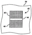
FIG. 2A is a simplified cross-sectional view of a printed image, referred to for discussion purposes as a "scrollbar", according to another embodiment of the present invention;
FIG. 3A is a simplified cross-sectional view of another embodiment of the present invention in which semi-circularly oriented flakes are formed in paint or ink for a rolling bar type image;
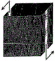
FIG. 3B is a simplified perspective view of the device according to FIG. 3A;
FIG. 4A is a plan view of an image comprised of non-aligned magnetic pigment flakes cured on a substrate;
FIG. 4B is a plan view of the flakes and substrate shown in FIG. 4A after the flakes have been aligned and permanently fixed by curing the pigment, thereby orienting them in a rolling bar similar to that of FIGS. 1A and 1B;
FIG. 5A is a plan view of an image having a curved upper profile of non-aligned magnetic pigment flakes;
FIG. 5B is a plan view of an image similar to that of FIG. 5A, in which the flakes are arranged in a large rolling bar, having a large radius of curvature;
FIG. 6 is a partial perspective view of a ball image in which the outline of the circle has a scrollbar that spans its diameter creating the illusion of a ball;
FIG. 7 is a shape similar to FIG. 5B, wherein both the upper and lower surfaces are curved;
FIG. 8A is an image of a perspective view of a container with one scrollbar in the outer front wall and another scrollbar in the inner rear wall, wherein the two scrollbars move in opposite directions simultaneously when the image is tilted in one direction of the arrows;
FIG. 8B is a cross-sectional view of the two scrollbars shown in FIG. 8C, shown on a different paper plane than FIG. 8A;
FIG. 8C is a plan view of a simpler arrangement of two scroll bars that move in opposite directions simultaneously when the image is tilted;
FIG. 9 is a perspective view of an image of a container similar to that shown in FIG. 8A, with the scrollbar shown on the adjacent outer and inner faces and the scrollbar moving in opposition, the scrollbar on the inner face changing area and shape when felt to move with tilting;
FIG. 10 is an image of a ball having two rolling elongated shapes that provide a 3-D realistic feel to the image when the image is tilted;
FIG. 11 is an image of a cylinder with a scrollbar on the outside of the cylinder toward the front surface;
FIG. 12 is an image of a shield with a scrollbar providing a motion effect and a scrollbar providing shadows and depths that increase the realism of the image that are not achievable by photography or painting;
FIG. 13 is an image of a hollow cylinder or tube with a double (concave and convex) scroll bar, where the concave scroll bar is on the inner wall and the two scroll bars move in opposite directions with the shadow of the actual object and the movement of the light;
FIGS. 14A to 14D show curved images with scroll bars at 4 different viewing angles;
FIG. 15A shows 4 sections of a separate clock printed on a rectangular base, with concave scroll bars printed on the inside of the clock and convex scroll bars printed on the outside of the clock;
FIG. 15B shows an image of a normal angle independent clock;
FIG. 15C shows the clock when the base is tilted to the right;
FIG. 15D shows the clock when the base is tilted to the left;
fig. 16A is a perspective view of a magnet constituting the magnet structure shown in fig. 16C for providing the dome-shaped magnetic field shown in fig. 16C;
FIG. 16B is a perspective view of magnets providing a dome-shaped magnetic field with some of the magnets removed for ease of viewing;
FIG. 16C is a perspective view of a magnet arrangement providing a dome-shaped magnetic field;
FIG. 16D is a perspective view of the magnet arrangement of FIG. 16C, wherein the paper with the flake ink thereon is disposed in a dome-shaped magnetic field, and the paper and the magnetic field are relatively rotated as indicated by the arrows in the two subsequent figures;
FIG. 16E is a perspective view similar to FIG. 16D with the paper positioned closer to the top of the dome-shaped magnetic field and the hemispherical image formed in the ink being smaller in size than FIG. 16D;
16F and 16G are images of a rolling 3-D hemisphere formed using the magnet of FIG. 16E shown in different positions as the image is tilted from one position to another;
FIG. 16H is a printed image of a hemisphere with a dome-shaped sheet disposed in a shroud image;
FIG. 16I is a printed image of a shield having a scrollbar formed along its axis;
FIG. 16J is a composite image of the images formed of FIGS. 16H and 16I, wherein the ink and magnetic field are applied in stages as the rolling hemisphere is formed, such that FIG. 16I is applied over FIG. 16H, with the central region coated only once;
FIG. 17A is a cross-sectional view of a bowl-shaped magnetic field used to form the image of FIG. 17C;
FIG. 17B is a cross-sectional view of pigment flakes in a carrier aligned in the magnetic field shown in FIG. 17A;
fig. 17C is an image of a magnetic flake forming an inverted hemisphere in the magnetic field of fig. 17A, which appears as a rolling bowl sinking into the page.
Detailed Description
I. Introduction to the design reside in
The present invention, in its various embodiments, provides a method of orienting magnetic flakes of optically variable ink or paint, which in some embodiments is suitable for high speed printing processes, while other embodiments are more suitable for manual alignment and printing processes. Additionally, some embodiments of the present invention require a multi-step printing process in which a first region of a substrate is printed with a magnetic flake ink and exposed to a magnetic field, and after curing, the same or different regions of the same substrate are printed with the ink and exposed to a second magnetic field. Typically, the particles of optically variable pigments dispersed in a liquid paint or ink solution, when printed or painted on a surface, are generally themselves oriented parallel to the surface. The orientation parallel to the surface has a high reflection of the incident light at the coated surface. The magnetic flakes can be tilted by applying a magnetic field while in a liquid medium. The general arrangement of the flakes is such that the longest diagonal of the flakes follows the magnetic field lines. Depending on the position and strength of the magnets, the magnetic field lines pass through the matrix at different angles, tilting the magnetic flakes to these angles. Oblique lamellae reflect incident light differently than lamellae that are parallel to the surface of the printed substrate. The reflection itself and the color can both be different. Oblique flakes generally appear darker and have a different color from flakes with parallel surfaces at typical viewing angles.
Oriented magnetic flakes in printed images have several problems. Many modern printing processes are faster than batch-type processes that apply magnets to a static (non-moving) coated article and hold the magnets in place while the paint or ink dries. In some printers, the speed of movement of the paper substrate is 100 and 160 m/min. Many sheets are stacked after one printing operation and transported to another operation. The inks used in these operations typically dry in milliseconds. Conventional processes are not suitable for these applications.
It has been found that one way to obtain an enhanced light effect in the paint/printed image is to orient the magnetic flakes perpendicular to the direction of motion of the substrate. In other words, with paint or printed liquid paint or ink media having dispersed flakes on a substrate, the movement of the magnetic field lines perpendicular to the magnetic field causes reorientation of the flakes. This orientation may provide a significant light illusion effect in the printed image.
One light effect, for discussion, will be referred to as a sports light effect. An illusive-motion light effect is generally to provide motion illusions in the printed image when the image is tilted relative to the viewing angle assumed to be a stationary illumination source. Another illusive light effect provides virtual depth to the printed two-dimensional image. Some images may provide both motion and virtual depth. Some images may provide an illusion or sensation of motion in any direction in the x-y plane. Another illusive light effect changes the appearance of the printed area, for example by changing between light and dark colours as the image is tilted back and forth. Another light effect is obtained by forming an image in which image features appear to change size when the image provides the illusion of motion. Creating a change in the size of an object, such as a scroll bar, will provide a realistic animation when the scroll bar appears to move.
Example of printing illusion image
Fig. 2A is a simplified cross-sectional view of the printed image 29 shown in U.S. patent application 20040051297 published as 3/18/2004, and referred to herein for purposes of discussion as a "scrollbar". Images formed of pigment flakes surrounded by a carrier such as an ink solution or paint have been arranged in a particular manner to provide a rolling bar effect. The sheet is shown as a short line in cross-section in fig. 2A. The flakes are magnetic flakes, i.e., pigment flakes aligned using a magnetic field. They may or may not retain residual magnetization. The figures are not drawn to scale. A typical sheet may be 20 microns wide and about 1 micron thick, so the drawings are merely illustrative. The image is printed or painted on a substrate 29 such as paper, plastic film, laminate, cardstock or other surface. For ease of discussion, the term "printing" is generally used to describe the application of pigments in a carrier to a surface, which may include other techniques, including other techniques that may be referred to as "painting".
Generally, a sheet is bright when viewed perpendicular to the plane of the sheet, and dark when viewed along the edges of the plane.
The support is typically transparent, either colorless or colored, and the flakes are typically relatively reflective. For example, the support may be green colored and the flakes may comprise a metal layer, such as a thin film of aluminum, gold, nickel, platinum or a metal alloy, or may be metal flakes, such as nickel or an alloy flake. Light reflected from the metal layer through the greenish carrier may appear bright green, while another portion with the foil viewed at one end may appear dark green or other color. If the flakes are simply metal flakes in a colorless carrier, some of the images may appear bright metallic while others are dark. In addition, the metal foil may be coated with a coloured layer, or the foil may comprise optical interference structures, such as absorber-spacer-reflector Fabry-Perot type structures. Also, diffractive structures may be formed on the reflective surface to provide additional and enhanced security features. The diffractive structure may be such that a simple linear grating is formed on the reflective surface, or may have a more complex predetermined pattern which is only visible when magnified, but has a combined effect when viewed. By providing a diffractive reflective layer, a viewer can see a color change or a brightness change by simply rotating a paper, a banknote or a structure having a diffractive flake.
Us patent 6692830 details the process of making diffractive flakes. Us patent application 20030190473 discloses the manufacture of colored diffractive flakes. Fabricating magnetic diffractive flakes is similar to fabricating diffractive flakes, but one of the layers needs to be magnetic. Indeed, the magnetic layer may be masked by being sandwiched between Al layers; in this way the magnetic layer then does not substantially affect the optical design of the lamella any more; or may simultaneously function as an optically active device, like an absorber, dielectric, or reflector in a thin film interference optical design.
Fig. 2A is a simplified cross-sectional view of a moving light "rolling bar" printed image 42 from U.S. patent application 20040051297 published by 3/18/2004. The image comprises pigment flakes 26 surrounded by a transparent carrier 28 printed on a substrate 29. The pigment flakes are arranged in a curved manner. With respect to back-tumbling, the scrollbar reflects light from the face of the pigment flakes to the area of the viewer and appears brighter than areas that do not directly reflect light to the viewer. This image provides a bright band or bar that appears to move ("scroll") across the image when the image is tilted relative to the viewing angle (assuming a fixed illumination source).
Fig. 1A is a simplified plan view of a scrollbar image 42 at a first selected viewing angle. The bright bar 44 appears in the first position of the image between the two contrasting areas 46, 48. FIG. 1B is a simplified plan view of a scrollbar image at a second selected viewing angle. The bright bar 44 ' appears to have "moved" to a second position in the image and the size of the contrasting areas 46 ' and 48 ' has changed. The arrangement of the pigment flakes, when the image is tilted (at a fixed viewing angle and fixed illumination), creates the illusion that the stripes "roll" down the image. Tilting the image in the other direction makes the bar appear to scroll in the opposite direction (up).
The strips may also be present with depth, even printed on a flat surface. The virtual depth appears to be greater than the physical thickness of the printed image. The tilting of the flakes in a selected pattern will reflect light, providing the illusion of depth or "3D", as it is commonly referred to. Three-dimensional effects can be achieved by placing a shaped magnet behind a paper or other substrate, with magnetic pigment flakes printed on the substrate in a fluid carrier. The flakes are aligned along the magnetic field lines and form a 3D image after the carrier is fixed (e.g., dried or cured). Images often appear to move as they tilt, and therefore can form moving 3D images.
Although a single rectangular scroll bar like that disclosed in us patent application 20040051297 has interesting effects, providing a moving rectangle on a larger rectangular background appears to somewhat limit its application.
Fig. 3A is a simplified cross-sectional view of semi-circular oriented flakes formed in paint or ink for a rolling bar type image. As shown, the thin permanent magnet 106 is magnetized throughout its thin cross-section. The magnet has circular flux lines 108 at its ends. A matrix 29 with printed magnetic flakes dispersed in a fluid carrier is moved with the magnets from the viewer into the paper. The flakes 26 are inclined in the direction of the magnetic field lines 108 and form a semi-circular pattern over the magnet.
Fig. 3B is a simplified perspective view of the device according to fig. 3A. The substrate 29 passes the magnet 106 in the direction of the arrow. The image 110 forms a scrollbar feature 114 that appears to move up and down as the image is tilted or the viewing angle is changed. The lamellae 26 are shown as being inclined with respect to the magnetic field lines. The image is typically very thin and the flakes are unlikely to form small bumps, as shown, but are substantially aligned along the magnetic field lines, thereby providing the desired arcuate reflective properties, creating a rolling bar effect. In one example, the scroll bar appears to scroll the image up and down as the image is tilted through an angle of 25 degrees.
It has been found that the strength of the scroll bar can be enhanced by chamfering 116 the trailing edge 118 of the magnet. It is believed that as the image passes the magnet, the magnetic field will gradually decrease. Otherwise, magnetic transitions that occur at sharp corners of the magnets can realign the orientation of the flakes and reduce the visual effect of the scrollbar. In a particular embodiment, the corners of the magnets are cut off diagonally along an angle of 30 degrees from the plane of the substrate. Another method is to secure the flakes before they pass over the trailing edge of the magnet. This can be achieved, for example, by providing a UV source in the lower part of the way that the magnet passes, for a UV-curing carrier, or a drying source for an evaporable carrier.
Referring now to fig. 5A, an image is shown having a 4-edged outline or occlusion area, wherein the top side edge is curved downward. It is worth noting that when viewing the image, the image has no special relation, and cannot be identified as a common object, and is only a two-dimensional polygon. On the other hand, when viewed, fig. 5B has the same contour and the same flakes as the well-known commonly recognizable object, but oriented differently, forming a cylinder. By providing a large scroll bar across zones, the scroll bar increases the shading so that the user feels depth and three dimensions. In addition to these phenomena produced by tilting the image shown in fig. 5B, which is composed of magnetically oriented pigment flakes, the scrollbar passes over the image as it sweeps across the cylinder and its area changes. FIG. 4B does not have the same association, and its dimensions do not change as the scrollbar appears to move in FIG. 4B. This change in the area of the scroll bar, which appears when viewing FIG. 5B, clearly makes the object look more realistic because the scroll bar contracts and then appears to expand in height. The scroll bar fills a smaller area when it appears to move from the center to the side, followed by a larger area. Furthermore, if comparing fig. 5A and 5B, the scroll bar in the curved upper region of fig. 5B appears to force the viewer to at least partially appreciate the presence of a white cap or interior to the cylinder. This does not occur when viewing fig. 4A, 4B or 5A. Therefore, filling a curved polygon with a scroll bar has several advantages. Fig. 6 and 7 show two other shapes of the scroll bar, where the scroll bar provides a sense of depth, motion, and the actual area of the bar changes as it sweeps across the image.
Referring now to fig. 12, there is shown a shroud having a profile of magnetically oriented pigment flakes oriented in such a way that the rolling bar has a large radius of curvature. It is important that the radius of curvature be selected to provide the desired depth and curvature perception, most closely reflecting the image formed. In all of the curved images described above, the presence of the scroll bar provides a perceptible change in the area of the scroll bar as the image is tilted, and the scroll bar appears to pass over the image. This phenomenon is quite noticeable and is represented by the sequence of fig. 14A to 14D. These figures are the same image tilted at different angles, with FIG. 14A at normal incidence and the angle of each subsequent figure increasing. In contrast to the simpler scroll bar of FIG. 4B, where the scroll bar simply appears to move from one position to the next, there is no reference to the change in appearance of the bar itself for the different positions. The bar of fig. 4B appears the same way in one position or another as it appears to move. However, the bars of fig. 14A and 14B have quite different shapes and the shape of the scroll bar changes continuously as the image tilts, greatly increasing the image appeal by defining and coordinating the bar motion presented, in combination with the change in bar and the lifting and lowering of the bar. Images with these features can be used as security features for articles, as decorations, or as means to provide the illusion of complex motion used in visual arts.
While the shape change of the scroll bar shown in fig. 5B, 6, 7, 10, 12 and 13 is not significant, it still presents and provides the illusion of lateral as well as up and down movement of the bar, as the bar follows a smooth curve.
Referring now to FIG. 6, a circle having a scrollbar across its diameter is shown. A circle without a scroll bar merely gives the viewer the impression of being a circle, but the presence of a scroll bar provides the viewer with the illusion that the object is a ball. Although the figure does not show motion, the viewer sees that the bars scrolling along the circle become significantly smaller as the image is tilted, and the bars move to the left, causing the viewer to perceive three dimensions and reality. This motion image provides the viewer with the perception that light and shading move past the ball as the image tilts, as opposed to viewing light and shading and highlighting fixed paintings. This figure has the sensation of moving around the object or seeing the object rotating. Furthermore, since the area of the bar decreases as it moves to the left, the viewer is made to perceive this object as more than just a picture or photograph. But for all intentions and purposes, flat images make the viewer feel depth and motion and enhance the viewing sensation compared to viewing "normal" images. Three-dimensional, motion and shape changes occur when viewing and tilting objects.
In FIG. 7, the scroll bar highlighted in the center, tapering to dark areas toward the sides, appears to sweep across the image, this area having a very uniform area, but the scroll bar appears to follow the curved trajectory of the upper and lower walls as it fills the outline and appears to extend out of the page, moving from the lower center position to the upper right maximum position or the upper left maximum position as it rises. Here, the viewer experiences a lateral and upward movement of the bar, as well as a 3-D effect.
Referring now to FIG. 8A, another embodiment of the present invention is shown wherein two scroll bars are designed to move in opposition at the same time when the image is tilted in one direction about the longitudinal axis of the scroll bar, e.g., an arrow pointing to the right.
In one embodiment of the invention, as shown in FIGS. 8B and 8C, the representation is an image having "double scroll bars" in which one portion 44' has magnetic flakes oriented in a convex manner and the other portion 44 "of the image has magnetic flakes oriented in a concave manner. To achieve this convex orientation, a "rolling bar" magnet is placed under the paper substrate. For the concave orientation, the magnet is placed on top of the paper substrate. A "double-slanted" image is formed when the magnetic flakes of the two regions of the image have different and opposite orientations, e.g., +30 degrees and-30 degrees. In an oblique position of the printed image, a part of the image is dark and another part is light. When the printed image is tilted in the opposite direction, these areas shift their bright and dark areas, so that the first image becomes bright and the second image becomes dark. This light and dark transition may occur from top to bottom to back, and from left to right to back, depending on the orientation of the sheet, depending on the intended design. In FIG. 8C, the bright bar 44 ' appears to "move" to the second position of the image, with the size of the contrast areas 46 ', 48 ' changing; in addition, the bright bars 44 "appear" to move "to different locations in the image, with the size of the contrasting areas 46", 48 "varying.
An embodiment according to the present invention shown in fig. 15A to 15D will be described below. An "independent clock" is shown in fig. 15B to 15D. In fig. 15A, the image is shown at a normal incident angle. In fig. 15B to 15D, it is shown that the same printing is inclined at different angles of incidence about the axis, as indicated by the arrows. As can be seen, the scroll bar 150 shown in FIG. 15B has a large radius of curvature, appearing to move to the left when viewing FIG. 15C, and the smaller concave inverted scroll bar 152 of the bell inner surface appears to move to the opposite side. Fig. 15D shows the opposite perceived motion, where the larger bar 150 when tilted in the opposite direction indicates that the large bar 150 appears to move to the right, while the smaller bar 152 appears to scroll to the left at the same time. The behavior of this light incident on the image simulates the lighting state of a real object, such as a free-standing clock. The light emission moves simultaneously and oppositely in different zones, as it is emitted from the real object. Thus, the illusion is designed to follow the natural photophysical laws of real objects. The illusion is that the image is real. Referring now to fig. 15A, for ease of understanding, the 4 parts 154a, 154b, 154c, 154d that make up the chimes are shown separated and each of these chimes is printed on the correct location on the substrate, one at a time, to form the image shown in fig. 15A. Although the image is formed by printing each region and applying magnets to form flakes arranged in an inverted arcuate pattern to form two scrolling strips, this process and similar images can also be accomplished using a sequential automated printing process.
The alternative embodiment of the invention shown in fig. 16F, 16G, 16H and 16J shows an interesting and surprising effect. Fig. 16F is a printed image of a hemisphere, where the entire image is coated with alignable pigment flakes. After the flakes are aligned, as explained, a hemisphere is formed. The printed image of the hemisphere shown in FIG. 16F appears as the image shown in FIG. 16G when the substrate is tilted or the light source is changed. When the image is tilted from vertical to left about a vertical axis passing through the center, it looks more like a bright hemisphere of a sphere, rolling as the tilt angle changes. In contrast to a scroll bar, which can roll in a plane along a straight line, the hemisphere of FIG. 16F can move or appear to move in any x-y direction with an oblique angle. Tilting the image about the x or y axis thus results in the occurrence of motion.
The shroud of fig. 16J provides a very interesting combination effect using a combination of a rolling bar and a hemisphere effect, where the shroud and hemisphere appear to extend out of the page. This is produced in a two stage process where the substrate is first coated with the magnetic coating and hemispheres are formed and cured as shown in fig. 16H. The second coating is formed through a mask or stencil to form the coating of fig. 16I, ensuring that no additional coating material covers the hemisphere. This second coating is placed in a magnetic field to form a rolling bar. The above-described method of forming a dynamic or moving hemisphere image is more complicated than the method of forming a scroll bar. With reference to fig. 16A-16E, this method will be described below. As an example, magnet 160a shown in fig. 16A represents magnetic lines of force above and below the magnet, forming two loops. This figure is intended to show only these two lines, but it is critical that the leading edge of the line be produced parallel to the lines, across the entire magnet. The magnets 160a, 160B used to create the hemisphere are more complex, as shown in fig. 16B, and in particular fig. 16C. The portion of the magnet of fig. 16B is cut away to show some of the magnetic field lines. As can be clearly seen in fig. 16C, the magnetic field extending above the set of magnets 160a, 160b, 160C is dome-shaped, as does the magnetic field extending below it. Printing of hemispherical moving images as shown in fig. 16D or 16E can be made by placing the coated substrate 167 with fluid ink in a dome-shaped magnetic field, just above the magnet as shown in fig. 16D, or with a large separation from the magnet, and supporting towards the middle of the field while rotating the magnet. In this illustrative example, the speed of the relative rotation of the magnet or image is about 120 rpm. The image is then taken from the magnetic field in this region and cured. The rotation speed of the magnet may be below or above 120rpm, depending on the magnetic properties of the particles and the viscosity of the ink vehicle. But if the speed is too low, the image quality is degraded.
Fig. 17A shows another embodiment, which is similar to, but reversed from, the image shown in fig. 16F. Fig. 17A shows a simulated magnetic field of a hemispherical magnet. This is the magnetic field shape that forms the image shown in fig. 17C. The north pole of the magnet is at the top and the particles are concentrically arranged in a funnel-like manner. Fig. 17B shows the magnetic field 194, with the flakes 193 in the carrier 192 disposed on the substrate 191 aligned in a funnel-like orientation with the magnetic field lines. This magnetic field produces bright moving spots 192 in the middle of the image 191, and the funnel-like arrangement of flakes produces dark moving spots in the middle of the image, in contrast to the hemispherical effect. Although the magnetic field is illustrated and described as being formed by a permanent magnet, in many embodiments an electric or electromagnetic field may be used. Of course, the magnetic field and the particles must be compatible so that the particles can be oriented by a particular magnetic field.
Although the present invention has been described above with reference to specific embodiments and the best mode for carrying out the invention, many modifications and substitutions will be apparent to those of ordinary skill in the art without departing from the scope and spirit of the invention. Accordingly, it is to be understood that the foregoing description is illustrative only and that the invention is defined by the following claims.
Claims (17)
1. A moving image, comprising:
a plurality of pigment flakes that fill areas to form at least a portion of the motion image,
wherein the plurality of pigment flakes are arranged so as to form a moving object within the moving image when the moving image is illuminated with a light source,
wherein the moving object is an optical effect presented to a viewer in the form of a rolling object,
wherein the rolling object provides shading and depth to the moving image, an
Wherein the rolling object is a rolling hemisphere.
2. A moving image as claimed in claim 1 wherein the shadows appear to move as the light source changes.
3. A moving image according to claim 1 wherein the plurality of pigment flakes are in a carrier coated on a substrate.
4. The moving image of claim 1, wherein another portion of the moving image produces another rolling object when the moving image is illuminated with the light source.
5. The moving image of claim 1, wherein the rolling object is disposed within a contour of a curved identifiable object.
6. A motion picture according to claim 1, wherein the scrolling object appears to move over the entire motion picture.
7. The moving image of claim 6, wherein the scrolling object appears to grow and shrink as the scrolling object moves across the moving image.
8. The motion picture according to claim 6, wherein the rolling object appears to move up and down while moving over the entire motion picture.
9. A moving picture according to claim 1,
wherein a first flake of the plurality of pigment flakes is in a first arched pattern to form a first contrast bar across at least a portion of the motion image, an
Wherein a second flake of the plurality of pigment flakes is in a second arcuate pattern to form a second contrast bar across at least a different portion of the motion image.
10. A moving image as claimed in claim 9 wherein the first and second contrast bars appear to move in different directions simultaneously when the moving image is tilted relative to a viewing angle.
11. The moving image according to claim 1, wherein an area of the rolling object changes when the moving image is tilted with respect to a viewing angle.
12. A moving image according to claim 1 wherein the moving image appears to move in the x-y direction depending on the tilt angle or the angle of incidence of the light source.
13. A method of forming a moving image, comprising:
providing a magnetic field;
providing a substrate having a coating of a plurality of pigment flakes;
placing the substrate within the magnetic field; and
relatively rotating the substrate and the magnetic field in such a manner that the plurality of pigment flakes are arranged so as to form a moving object within a portion of the moving image when the moving image is irradiated with a light source,
wherein the moving object is an optical effect presented to a viewer in the form of a rolling object, an
Wherein the rolling object is in the appearance of a rolling ball when the moving image is tilted or the light source illuminating the moving image is changed.
14. The method of claim 13, wherein the rolling object provides shading and depth to the moving image.
15. The method of claim 13, wherein the rolling object appears to expand and contract as the rolling object moves across the moving image.
16. The method of claim 13, wherein another portion of the motion image produces another rolling object when the motion image is illuminated with the light source.
17. The method of claim 13, wherein the magnetic field is a rounded dome magnetic field.
Applications Claiming Priority (5)
| Application Number | Priority Date | Filing Date | Title |
|---|---|---|---|
| US11/022,106 US7517578B2 (en) | 2002-07-15 | 2004-12-22 | Method and apparatus for orienting magnetic flakes |
| US11/022,106 | 2004-12-22 | ||
| US11/313,165 US7604855B2 (en) | 2002-07-15 | 2005-12-20 | Kinematic images formed by orienting alignable flakes |
| US11/313,165 | 2005-12-20 | ||
| CN2005800445470A CN101437673B (en) | 2004-12-22 | 2005-12-21 | Kinematic images formed by orienting alignable flakes |
Related Parent Applications (1)
| Application Number | Title | Priority Date | Filing Date |
|---|---|---|---|
| CN2005800445470A Division CN101437673B (en) | 2004-12-22 | 2005-12-21 | Kinematic images formed by orienting alignable flakes |
Publications (2)
| Publication Number | Publication Date |
|---|---|
| CN107185788A CN107185788A (en) | 2017-09-22 |
| CN107185788B true CN107185788B (en) | 2021-03-16 |
Family
ID=36602315
Family Applications (4)
| Application Number | Title | Priority Date | Filing Date |
|---|---|---|---|
| CN201710475226.0A Active CN107185788B (en) | 2004-12-22 | 2005-12-21 | Motion image formed by orienting alignable flakes |
| CN201510628690.XA Active CN105291631B (en) | 2004-12-22 | 2005-12-21 | By orientation can aligning flakes formation moving image |
| CN2005800445470A Active CN101437673B (en) | 2004-12-22 | 2005-12-21 | Kinematic images formed by orienting alignable flakes |
| CN201210145595.0A Active CN102673299B (en) | 2004-12-22 | 2005-12-21 | By orientation can aligning flakes formed moving image |
Family Applications After (3)
| Application Number | Title | Priority Date | Filing Date |
|---|---|---|---|
| CN201510628690.XA Active CN105291631B (en) | 2004-12-22 | 2005-12-21 | By orientation can aligning flakes formation moving image |
| CN2005800445470A Active CN101437673B (en) | 2004-12-22 | 2005-12-21 | Kinematic images formed by orienting alignable flakes |
| CN201210145595.0A Active CN102673299B (en) | 2004-12-22 | 2005-12-21 | By orientation can aligning flakes formed moving image |
Country Status (9)
| Country | Link |
|---|---|
| US (1) | US7604855B2 (en) |
| EP (1) | EP1674282B1 (en) |
| JP (1) | JP5117195B2 (en) |
| KR (1) | KR101319514B1 (en) |
| CN (4) | CN107185788B (en) |
| AU (2) | AU2005319097B2 (en) |
| CA (1) | CA2588380C (en) |
| HK (2) | HK1176038A1 (en) |
| WO (1) | WO2006069218A2 (en) |
Families Citing this family (72)
| Publication number | Priority date | Publication date | Assignee | Title |
|---|---|---|---|---|
| US7047883B2 (en) | 2002-07-15 | 2006-05-23 | Jds Uniphase Corporation | Method and apparatus for orienting magnetic flakes |
| US7625632B2 (en) * | 2002-07-15 | 2009-12-01 | Jds Uniphase Corporation | Alignable diffractive pigment flakes and method and apparatus for alignment and images formed therefrom |
| US11230127B2 (en) | 2002-07-15 | 2022-01-25 | Viavi Solutions Inc. | Method and apparatus for orienting magnetic flakes |
| US7934451B2 (en) | 2002-07-15 | 2011-05-03 | Jds Uniphase Corporation | Apparatus for orienting magnetic flakes |
| US8025952B2 (en) | 2002-09-13 | 2011-09-27 | Jds Uniphase Corporation | Printed magnetic ink overt security image |
| US7645510B2 (en) | 2002-09-13 | 2010-01-12 | Jds Uniphase Corporation | Provision of frames or borders around opaque flakes for covert security applications |
| US9458324B2 (en) | 2002-09-13 | 2016-10-04 | Viava Solutions Inc. | Flakes with undulate borders and method of forming thereof |
| US9164575B2 (en) | 2002-09-13 | 2015-10-20 | Jds Uniphase Corporation | Provision of frames or borders around pigment flakes for covert security applications |
| US7674501B2 (en) * | 2002-09-13 | 2010-03-09 | Jds Uniphase Corporation | Two-step method of coating an article for security printing by application of electric or magnetic field |
| CA2523648C (en) * | 2004-10-20 | 2014-05-13 | Jds Uniphase Corporation | Alignment of paste-like ink having magnetic particles therein, and the printing of optical effects |
| TWI402106B (en) | 2005-04-06 | 2013-07-21 | Jds Uniphase Corp | Dynamic appearance-changing optical devices (dacod) printed in a shaped magnetic field including printable fresnel structures |
| SG132628A1 (en) | 2005-11-18 | 2007-06-28 | Jds Uniphase Corp | Magnetic plate for printing of optical effects |
| US10343436B2 (en) | 2006-02-27 | 2019-07-09 | Viavi Solutions Inc. | Security device formed by printing with special effect inks |
| CA2582010A1 (en) * | 2006-03-21 | 2007-09-21 | Jds Uniphase Corporation | Brand protection label with a tamper evident abrasion-removable magnetic ink |
| CA2592667C (en) | 2006-07-12 | 2014-05-13 | Jds Uniphase Corporation | Stamping a coating of cured field aligned special effect flakes and image formed thereby |
| DE102006057507A1 (en) * | 2006-12-06 | 2008-06-12 | Merck Patent Gmbh | Optically variable security element |
| AU2008219354B2 (en) | 2007-09-19 | 2014-02-13 | Viavi Solutions Inc. | Anisotropic magnetic flakes |
| US20090123699A1 (en) | 2007-11-09 | 2009-05-14 | Motorola, Inc. | Viewable surface having unnoticeable smudges |
| WO2009092984A1 (en) * | 2008-01-23 | 2009-07-30 | De La Rue International Limited | Optically variable magnetic stripe assembly |
| JP2009193069A (en) | 2008-02-13 | 2009-08-27 | Jds Uniphase Corp | Medium for laser printing including optical special effect flake |
| FR2942244B1 (en) * | 2009-02-16 | 2011-04-15 | Arjowiggins Security | METHOD FOR CREATING VISUAL ANIMATION ON A SUPPORT |
| JP5570305B2 (en) * | 2009-11-06 | 2014-08-13 | 富士フイルム株式会社 | Heat ray shielding material |
| GB201001603D0 (en) * | 2010-02-01 | 2010-03-17 | Rue De Int Ltd | Security elements, and methods and apparatus for their manufacture |
| AU2015200595B2 (en) * | 2010-02-01 | 2016-08-18 | De La Rue International Limited | Security elements and methods and apparatus for their manufacture |
| WO2012084143A1 (en) * | 2010-12-21 | 2012-06-28 | Merck Patent Gmbh | Coloured magnetizable security element |
| PL2468423T3 (en) | 2010-12-27 | 2016-11-30 | System and method for forming an image on a substrate | |
| EP2484455B1 (en) * | 2011-02-07 | 2014-12-24 | Sicpa Holding Sa | Device displaying a dynamic visual motion effect and method for producing same |
| US8616461B2 (en) * | 2011-07-13 | 2013-12-31 | Eastman Kodak Company | Printed dynamic optical illusion images |
| US8616460B2 (en) * | 2011-07-13 | 2013-12-31 | Eastman Kodak Company | Method for providing dynamic optical illusion images |
| IN2014MN01816A (en) | 2012-01-12 | 2015-06-12 | Jds Uniphase Corp | |
| US11073959B2 (en) * | 2012-06-08 | 2021-07-27 | Apple Inc. | Simulating physical materials and light interaction in a user interface of a resource-constrained device |
| US20150331160A1 (en) * | 2012-12-04 | 2015-11-19 | Sectago Gmbh | Security device |
| BR112015011390B1 (en) | 2013-01-09 | 2021-06-22 | Sicpa Holding Sa | OPTICAL EFFECT LAYER (OEL), USE AND PROCESS FOR THE PRODUCTION OF THE SAME, OPTICAL EFFECT LAYER COATED SUBSTRATE, MAGNETIC FIELD GENERATOR DEVICE, USE OF THE SAME, PRINTING SET AND SAFETY DOCUMENT |
| AR094362A1 (en) * | 2013-01-09 | 2015-07-29 | Sicpa Holding Sa | LAYERS OF OPTICAL EFFECTS THAT SHOW AN OPTICAL EFFECT THAT DEPENDS ON THE VISION ANGLE; PROCESSES AND DEVICES FOR THE PRODUCTION OF THESE LAYERS, ITEMS THAT HAVE A LAYER OF OPTICAL EFFECTS AND USES OF THESE LAYERS |
| US8789925B1 (en) | 2013-02-01 | 2014-07-29 | Xerox Corporation | Method and apparatus for printing of magnetic inks |
| DE102013002137A1 (en) * | 2013-02-07 | 2014-08-07 | Giesecke & Devrient Gmbh | Optically variable surface pattern |
| CN105339179B (en) * | 2013-02-12 | 2018-06-22 | 赛克达戈有限公司 | Safety device |
| KR20160002943A (en) * | 2013-05-02 | 2016-01-08 | 시크파 홀딩 에스에이 | Processes for producing security threads or stripes |
| TWI641660B (en) | 2013-08-05 | 2018-11-21 | 瑞士商西克帕控股有限公司 | Magnetic or magnetisable pigment particles and optical effect layers |
| US10207531B2 (en) * | 2013-12-02 | 2019-02-19 | SECTAG GmbH | Security device |
| RU2641864C2 (en) | 2013-12-11 | 2018-01-22 | Сикпа Холдинг Са | Optically variable security threads and strips |
| ES2755149T3 (en) | 2013-12-13 | 2020-04-21 | Sicpa Holding Sa | Processes to produce effect layers |
| EP3105064B1 (en) * | 2014-02-13 | 2017-09-13 | Sicpa Holding SA | Security threads and stripes |
| FR3019496A1 (en) * | 2014-04-07 | 2015-10-09 | Hologram Ind | OPTICAL SECURITY COMPONENT WITH REFLECTIVE EFFECT, MANUFACTURE OF SUCH A COMPONENT AND SECURE DOCUMENT EQUIPPED WITH SUCH A COMPONENT |
| PT2965920T (en) | 2014-07-09 | 2018-01-16 | Sicpa Holding Sa | Optically variable magnetic security threads and stripes |
| JP6705092B2 (en) | 2014-07-30 | 2020-06-03 | シクパ ホルディング ソシエテ アノニムSicpa Holding Sa | Belt driven method for producing optical effect layers |
| DE102015005911A1 (en) * | 2015-05-07 | 2016-11-10 | Giesecke & Devrient Gmbh | Optically variable security element |
| DE102015005969A1 (en) * | 2015-05-08 | 2016-11-10 | Giesecke & Devrient Gmbh | Optically variable security element |
| TWI709626B (en) * | 2015-10-15 | 2020-11-11 | 瑞士商西克帕控股有限公司 | Magnetic assemblies and processes for producing optical effect layers comprising oriented non-spherical magnetic or magnetizable pigment particles |
| UA121510C2 (en) | 2015-11-10 | 2020-06-10 | Сікпа Холдінг Са | Apparatuses and processes for producing optical effect layers comprising oriented non-spherical magnetic or magnetizable pigment particles |
| AR107681A1 (en) | 2016-02-29 | 2018-05-23 | Sicpa Holding Sa | APPLIANCES AND PROCESSES TO PRODUCE LAYERS WITH OPTICAL EFFECT THAT INCLUDE MAGNETIC ORIENTED OR MAGNETIZABLE ORPHERIC PIGMENT PARTICLES |
| EP3178569A1 (en) | 2016-06-29 | 2017-06-14 | Sicpa Holding Sa | Processes and devices for producing optical effect layers using a photomask |
| US11193002B2 (en) | 2016-08-31 | 2021-12-07 | Viavi Solutions Inc. | Orienting magnetically-orientable flakes |
| RU2754983C2 (en) | 2016-08-31 | 2021-09-08 | Виави Солюшнз Инк. | Product with inclined reflective segments |
| US10357991B2 (en) | 2016-12-19 | 2019-07-23 | Viavi Solutions Inc. | Security ink based security feature |
| EP3421551A1 (en) * | 2017-06-28 | 2019-01-02 | Andres Ruiz Quevedo | Effect pigment |
| TWI768096B (en) * | 2017-08-25 | 2022-06-21 | 瑞士商西克帕控股有限公司 | Optical effect layer, apparatus and process for producing such optical effect layer, and use of the apparatus |
| TWI772576B (en) | 2018-01-17 | 2022-08-01 | 瑞士商西克帕控股有限公司 | Processes for producing optical effects layers |
| DE102018000385A1 (en) | 2018-01-18 | 2019-07-18 | Giesecke+Devrient Currency Technology Gmbh | Setting magnet for the production of security elements with magnetically oriented effect pigments and production method for such setting magnets |
| US10618340B2 (en) | 2018-05-16 | 2020-04-14 | Viavi Solutions Inc. | Security feature based on a single axis alignment of mirrors in a structured surface that forms a micro mirror array |
| US10642214B2 (en) * | 2018-08-13 | 2020-05-05 | Viavi Solutions Inc. | Optical security device based on a surface of revolution |
| DE102018008146A1 (en) * | 2018-10-15 | 2020-04-16 | Giesecke+Devrient Currency Technology Gmbh | Security element with microreflectors for the perspective representation of a motif |
| SG11202109245YA (en) | 2019-02-28 | 2021-09-29 | Sicpa Holding Sa | Verifiable access credential |
| TW202100960A (en) | 2019-02-28 | 2021-01-01 | 瑞士商西克帕控股有限公司 | Method for authenticating a magnetically induced mark with a portable device |
| CN110143076B (en) * | 2019-05-28 | 2021-08-31 | 成都印钞有限公司 | Magnetism fixing method for magnetic optically variable ink |
| CN111776471B (en) * | 2019-08-16 | 2022-07-12 | 西安印钞有限公司 | Scene change anti-counterfeiting structure, anti-counterfeiting plastic package and preparation method |
| CN111645411B (en) * | 2020-05-13 | 2022-07-26 | 惠州市华阳光学技术有限公司 | Magnetic orientation device and printing equipment |
| BR112022023694A2 (en) | 2020-05-26 | 2022-12-20 | Sicpa Holding Sa | MAGNETIC ASSEMBLIES AND METHODS FOR PRODUCING OPTICAL EFFECT LAYERS COMPRISING ORIENTED PLATELET-FORMED MAGNETIC OR MAGNETIZABLE PIGMENT PARTICLES |
| KR20230025524A (en) | 2020-06-23 | 2023-02-21 | 시크파 홀딩 에스에이 | Method for producing an optical effect layer comprising magnetic or magnetisable pigment particles |
| TW202239482A (en) | 2021-03-31 | 2022-10-16 | 瑞士商西克帕控股有限公司 | Methods for producing optical effect layers comprising magnetic or magnetizable pigment particles and exhibiting one or more indicia |
| WO2023161464A1 (en) | 2022-02-28 | 2023-08-31 | Sicpa Holding Sa | Methods for producing optical effect layers comprising magnetic or magnetizable pigment particles and exhibiting one or more indicia |
| WO2024028408A1 (en) | 2022-08-05 | 2024-02-08 | Sicpa Holding Sa | Methods for producing optical effect layers comprising magnetic or magnetizable pigment particles and exhibiting one or more indicia |
Citations (1)
| Publication number | Priority date | Publication date | Assignee | Title |
|---|---|---|---|---|
| US5364689A (en) * | 1992-02-21 | 1994-11-15 | Hashimoto Forming Industry Co., Ltd. | Painting with magnetically formed pattern and painted product with magnetically formed pattern |
Family Cites Families (107)
| Publication number | Priority date | Publication date | Assignee | Title |
|---|---|---|---|---|
| US2570856A (en) | 1947-03-25 | 1951-10-09 | Du Pont | Process for obtaining pigmented films |
| NL277968A (en) | 1961-05-04 | |||
| DE1253730B (en) | 1964-06-05 | 1967-11-09 | Agfa Ag | Process for the complete or partial printing of a printing form and rotary duplicator to carry out the process |
| FR1440147A (en) | 1965-04-15 | 1966-05-27 | Tefal Sa | A method of decorating, in the mass, a translucent plastic material |
| US3627580A (en) | 1969-02-24 | 1971-12-14 | Eastman Kodak Co | Manufacture of magnetically sensitized webs |
| US3845499A (en) | 1969-09-25 | 1974-10-29 | Honeywell Inc | Apparatus for orienting magnetic particles having a fixed and varying magnetic field component |
| US3633720A (en) | 1969-09-25 | 1972-01-11 | Honeywell Inc | Alphanumeric printing device employing magnetically positionable particles |
| US3610721A (en) | 1969-10-29 | 1971-10-05 | Du Pont | Magnetic holograms |
| US3853676A (en) | 1970-07-30 | 1974-12-10 | Du Pont | Reference points on films containing curved configurations of magnetically oriented pigment |
| US3676273A (en) | 1970-07-30 | 1972-07-11 | Du Pont | Films containing superimposed curved configurations of magnetically orientated pigment |
| IT938725B (en) | 1970-11-07 | 1973-02-10 | Magnetfab Bonn Gmbh | PROCEDURE AND DEVICE FOR EIGHT BLACK DRAWINGS IN SURFACE LAYERS BY MEANS OF MAGNETIC FIELDS |
| US3790407A (en) | 1970-12-28 | 1974-02-05 | Ibm | Recording media and method of making |
| US3873975A (en) | 1973-05-02 | 1975-03-25 | Minnesota Mining & Mfg | System and method for authenticating and interrogating a magnetic record medium |
| US4054992A (en) * | 1974-05-30 | 1977-10-25 | Weed Eater, Inc. | Rotary cutting assembly |
| DE2520581C3 (en) | 1975-05-09 | 1980-09-04 | Kienzle Apparate Gmbh, 7730 Villingen-Schwenningen | Arrangement for erasable recording of measured quantities |
| US4011009A (en) | 1975-05-27 | 1977-03-08 | Xerox Corporation | Reflection diffraction grating having a controllable blaze angle |
| US4099838A (en) | 1976-06-07 | 1978-07-11 | Minnesota Mining And Manufacturing Company | Reflective sheet material |
| DE2752895A1 (en) | 1976-12-06 | 1978-06-08 | Emi Ltd | METHOD FOR PRODUCING A MATERIAL LAYER, THE SURFACE OF WHICH HAS A SCANABLE PATTERN, AS WELL AS A SECURITY DOCUMENT SYSTEM |
| FR2408890A1 (en) | 1977-11-10 | 1979-06-08 | Transac Dev Transact Automat | METHOD AND DEVICE FOR ORIENTATION AND FIXATION IN A DETERMINED DIRECTION OF MAGNETIC PARTICLES CONTAINED IN A POLYMERISABLE INK |
| US4271782A (en) | 1978-06-05 | 1981-06-09 | International Business Machines Corporation | Apparatus for disorienting magnetic particles |
| US4398798A (en) | 1980-12-18 | 1983-08-16 | Sperry Corporation | Image rotating diffraction grating |
| US4543551A (en) | 1984-07-02 | 1985-09-24 | Polaroid Corporation | Apparatus for orienting magnetic particles in recording media |
| US4788116A (en) | 1986-03-31 | 1988-11-29 | Xerox Corporation | Full color images using multiple diffraction gratings and masking techniques |
| DE3617430A1 (en) | 1986-05-23 | 1987-11-26 | Merck Patent Gmbh | PEARL PIGMENT |
| JPH0694543B2 (en) | 1987-01-09 | 1994-11-24 | 三菱自動車工業株式会社 | Paint |
| WO1988007214A1 (en) | 1987-03-10 | 1988-09-22 | Precis (549) Limited | Light reflective materials |
| US4798116A (en) * | 1987-09-04 | 1989-01-17 | Silver Marc L | Document shredding machine |
| JP2514828B2 (en) | 1988-01-18 | 1996-07-10 | 富士写真フイルム株式会社 | Method of manufacturing magnetic recording medium |
| US4838648A (en) | 1988-05-03 | 1989-06-13 | Optical Coating Laboratory, Inc. | Thin film structure having magnetic and color shifting properties |
| US5186787A (en) | 1988-05-03 | 1993-02-16 | Phillips Roger W | Pre-imaged high resolution hot stamp transfer foil, article and method |
| JPH0298811A (en) | 1988-10-05 | 1990-04-11 | Fuji Photo Film Co Ltd | Magnetic recording medium |
| US5192611A (en) | 1989-03-03 | 1993-03-09 | Kansai Paint Co., Ltd. | Patterned film forming laminated sheet |
| US5079058A (en) | 1989-03-03 | 1992-01-07 | Kansai Paint Co., Ltd. | Patterned film forming laminated sheet |
| DE69015900T2 (en) | 1989-06-27 | 1995-06-22 | Nippon Paint Co Ltd | Process for making a patterned coating. |
| DE3938055A1 (en) * | 1989-11-16 | 1991-05-23 | Merck Patent Gmbh | MATERIALS COATED WITH PLAIN-SHAPED PIGMENTS |
| US5177344A (en) | 1990-10-05 | 1993-01-05 | Rand Mcnally & Company | Method and appparatus for enhancing a randomly varying security characteristic |
| JP2857276B2 (en) * | 1992-02-21 | 1999-02-17 | 橋本フォーミング工業株式会社 | Magnetic painting |
| JPH05337436A (en) * | 1992-06-11 | 1993-12-21 | Hashimoto Forming Ind Co Ltd | Molded goods having pattern of prescribed shape and manufacture thereof |
| JP2774015B2 (en) * | 1992-04-10 | 1998-07-09 | 橋本フォーミング工業株式会社 | Vehicle wheel cover and method of manufacturing the same |
| DE4212290C2 (en) | 1992-02-29 | 1996-08-01 | Kurz Leonhard Fa | value document |
| DE69303651T2 (en) | 1992-03-13 | 1997-01-02 | Fuji Photo Film Co Ltd | Magnetic recording medium and method for its production |
| US5672410A (en) | 1992-05-11 | 1997-09-30 | Avery Dennison Corporation | Embossed metallic leafing pigments |
| US5991078A (en) | 1992-08-19 | 1999-11-23 | Dai Nippon Printing Co., Ltd. | Display medium employing diffraction grating and method of producing diffraction grating assembly |
| JP2655551B2 (en) | 1992-09-09 | 1997-09-24 | 工業技術院長 | Fine surface shape creation method |
| JPH08508834A (en) | 1993-04-06 | 1996-09-17 | コモンウェルス・サイエンティフィック・アンド・インダストリアル・リサーチ・オーガニゼイション | Optical data element |
| CA2144996C (en) | 1993-07-16 | 2004-09-07 | Jefferson E. Odhner | Diffractive display utilizing reflective or transmissive light yielding single pixel full color capability |
| US6033782A (en) | 1993-08-13 | 2000-03-07 | General Atomics | Low volume lightweight magnetodielectric materials |
| EP0644508B1 (en) | 1993-08-31 | 1999-12-22 | Control Module, Inc. | Secure optical identification method and means |
| DE4335308C2 (en) | 1993-10-16 | 1995-12-14 | Daimler Benz Ag | Identification of vehicles to make theft and / or unauthorized sale more difficult |
| US5415950A (en) | 1993-11-08 | 1995-05-16 | E. I. Du Pont De Nemours And Company | Holographic flake pigment |
| US5424119A (en) | 1994-02-04 | 1995-06-13 | Flex Products, Inc. | Polymeric sheet having oriented multilayer interference thin film flakes therein, product using the same and method |
| KR100362350B1 (en) * | 1994-03-16 | 2003-02-19 | 오브이디 키네그람 악티엔게젤샤프트 | Optical carrier with optical label |
| DE4439455A1 (en) | 1994-11-04 | 1996-05-09 | Basf Ag | Process for the production of coatings with three-dimensional optical effects |
| CA2238284C (en) * | 1995-11-13 | 2006-08-08 | Orell Fussli Banknote Engineering Ltd. | Security document with security marking |
| GB9524862D0 (en) | 1995-12-06 | 1996-02-07 | The Technology Partnership Plc | Colour diffractive structure |
| AUPO728397A0 (en) | 1997-06-11 | 1997-07-03 | Securency Pty Ltd | Security document including a magnetic watermark and method of production thereof |
| US6103361A (en) | 1997-09-08 | 2000-08-15 | E. I. Du Pont De Nemours And Company | Patterned release finish |
| US6168100B1 (en) | 1997-10-23 | 2001-01-02 | Toyota Jidosha Kabushiki Kaisha | Method for producing embossed metallic flakelets |
| US6549131B1 (en) | 1999-10-07 | 2003-04-15 | Crane & Co., Inc. | Security device with foil camouflaged magnetic regions and methods of making same |
| EP0953937A1 (en) | 1998-04-30 | 1999-11-03 | Securency Pty. Ltd. | Security element to prevent counterfeiting of value documents |
| ES2373215T3 (en) | 1998-08-06 | 2012-02-01 | Sicpa Holding S.A. | INORGANIC SHEET FOR THE PRODUCTION OF PIGMENTS. |
| US6643001B1 (en) | 1998-11-20 | 2003-11-04 | Revco, Inc. | Patterned platelets |
| US6150022A (en) | 1998-12-07 | 2000-11-21 | Flex Products, Inc. | Bright metal flake based pigments |
| US6692031B2 (en) | 1998-12-31 | 2004-02-17 | Mcgrew Stephen P. | Quantum dot security device and method |
| US7047883B2 (en) * | 2002-07-15 | 2006-05-23 | Jds Uniphase Corporation | Method and apparatus for orienting magnetic flakes |
| US7517578B2 (en) | 2002-07-15 | 2009-04-14 | Jds Uniphase Corporation | Method and apparatus for orienting magnetic flakes |
| US6987590B2 (en) | 2003-09-18 | 2006-01-17 | Jds Uniphase Corporation | Patterned reflective optical structures |
| US6761959B1 (en) | 1999-07-08 | 2004-07-13 | Flex Products, Inc. | Diffractive surfaces with color shifting backgrounds |
| US7667895B2 (en) | 1999-07-08 | 2010-02-23 | Jds Uniphase Corporation | Patterned structures with optically variable effects |
| US6545809B1 (en) | 1999-10-20 | 2003-04-08 | Flex Products, Inc. | Color shifting carbon-containing interference pigments |
| US6649256B1 (en) | 2000-01-24 | 2003-11-18 | General Electric Company | Article including particles oriented generally along an article surface and method for making |
| US6554044B2 (en) * | 2000-01-28 | 2003-04-29 | Fargo Electronics Inc. | Laminator peel-off bar |
| US6310720B1 (en) * | 2000-06-02 | 2001-10-30 | Genoa Corporation | Polarization insensitive semiconductor optical amplifier |
| DE10032128A1 (en) * | 2000-07-05 | 2002-01-17 | Giesecke & Devrient Gmbh | Security paper and value document made from it |
| US6586098B1 (en) | 2000-07-27 | 2003-07-01 | Flex Products, Inc. | Composite reflective flake based pigments comprising reflector layers on bothside of a support layer |
| DE10044465A1 (en) * | 2000-09-08 | 2002-03-21 | Giesecke & Devrient Gmbh | Data carrier with an optically variable element |
| US6686027B1 (en) | 2000-09-25 | 2004-02-03 | Agra Vadeko Inc. | Security substrate for documents of value |
| JP2002200871A (en) * | 2000-10-24 | 2002-07-16 | Konica Corp | Image recording body, forming method thereof and authentication discriminating method using thereof |
| US20020110672A1 (en) * | 2001-02-12 | 2002-08-15 | Joanne Muratore-Pallatino | Cosmetic skin tattoo |
| EP1239307A1 (en) | 2001-03-09 | 2002-09-11 | Sicpa Holding S.A. | Magnetic thin film interference device |
| DE10114445A1 (en) | 2001-03-23 | 2002-09-26 | Eckart Standard Bronzepulver | Flat metal oxide-covered white iron pigment used for paint and printing comprises substrate of reduced carbonyl iron powder and oxide coating of transparent or selectively absorbent metal oxide |
| US7033653B2 (en) * | 2001-04-24 | 2006-04-25 | Merck Patent Gmbh | Birefringent marking |
| US20020160194A1 (en) | 2001-04-27 | 2002-10-31 | Flex Products, Inc. | Multi-layered magnetic pigments and foils |
| US6808806B2 (en) * | 2001-05-07 | 2004-10-26 | Flex Products, Inc. | Methods for producing imaged coated articles by using magnetic pigments |
| ITMO20010084A1 (en) * | 2001-05-08 | 2002-11-08 | G S Srl Unipersonale | METHOD TO REALIZE THE READING OF INTERACTION FRACTIONS BETWEEN THE PHOTOSENSITIVE ELEMENTS OR CONTINUOUS PIXELS OF A LINEAR OPTICAL SENSOR |
| US6902807B1 (en) | 2002-09-13 | 2005-06-07 | Flex Products, Inc. | Alignable diffractive pigment flakes |
| US6749936B2 (en) | 2001-12-20 | 2004-06-15 | Flex Products, Inc. | Achromatic multilayer diffractive pigments and foils |
| US6841238B2 (en) | 2002-04-05 | 2005-01-11 | Flex Products, Inc. | Chromatic diffractive pigments and foils |
| US7625632B2 (en) | 2002-07-15 | 2009-12-01 | Jds Uniphase Corporation | Alignable diffractive pigment flakes and method and apparatus for alignment and images formed therefrom |
| US6692830B2 (en) | 2001-07-31 | 2004-02-17 | Flex Products, Inc. | Diffractive pigment flakes and compositions |
| KR20030044255A (en) * | 2001-11-29 | 2003-06-09 | 한국전자통신연구원 | Optical module package of flip chip bonding and packaging method thereof |
| CN2528075Y (en) * | 2002-03-07 | 2002-12-25 | 河北格林光电技术有限公司 | Lighting antifalse marker |
| WO2003088343A1 (en) * | 2002-04-10 | 2003-10-23 | Honeywell International, Inc. | New porogens for porous silica dielectric for integral circuit applications |
| US6815065B2 (en) | 2002-05-31 | 2004-11-09 | Flex Products, Inc. | All-dielectric optical diffractive pigments |
| US7258900B2 (en) | 2002-07-15 | 2007-08-21 | Jds Uniphase Corporation | Magnetic planarization of pigment flakes |
| US7241489B2 (en) | 2002-09-13 | 2007-07-10 | Jds Uniphase Corporation | Opaque flake for covert security applications |
| US7645510B2 (en) | 2002-09-13 | 2010-01-12 | Jds Uniphase Corporation | Provision of frames or borders around opaque flakes for covert security applications |
| US7674501B2 (en) | 2002-09-13 | 2010-03-09 | Jds Uniphase Corporation | Two-step method of coating an article for security printing by application of electric or magnetic field |
| US7258915B2 (en) | 2003-08-14 | 2007-08-21 | Jds Uniphase Corporation | Flake for covert security applications |
| JP2004122542A (en) * | 2002-10-01 | 2004-04-22 | Canon Inc | Laminated film and laminated print |
| US8236406B2 (en) * | 2002-11-20 | 2012-08-07 | Kimoto Co., Ltd. | Fingerprint easily erasible film |
| JP2006517361A (en) * | 2003-01-06 | 2006-07-20 | コーニンクレッカ フィリップス エレクトロニクス エヌ ヴィ | Method and apparatus for improving synchronization stability of audio / video signal in digital recording equipment |
| TWI334382B (en) | 2003-07-14 | 2010-12-11 | Flex Products Inc | Vacuum roll coated security thin film interference products with overt and/or covert patterned layers |
| US7029525B1 (en) | 2003-10-21 | 2006-04-18 | The Standard Register Company | Optically variable water-based inks |
| CN1283472C (en) * | 2003-12-17 | 2006-11-08 | 吴德明 | A three-dimensional picture, its manufacturing process and use thereof |
| EP1719636A1 (en) | 2005-05-04 | 2006-11-08 | Sicpa Holding S.A. | Black-to-color shifting security element |
| CA2564764C (en) | 2005-10-25 | 2014-05-13 | Jds Uniphase Corporation | Patterned optical structures with enhanced security feature |
-
2005
- 2005-12-20 US US11/313,165 patent/US7604855B2/en active Active
- 2005-12-21 CN CN201710475226.0A patent/CN107185788B/en active Active
- 2005-12-21 CN CN201510628690.XA patent/CN105291631B/en active Active
- 2005-12-21 KR KR1020077013991A patent/KR101319514B1/en active IP Right Grant
- 2005-12-21 AU AU2005319097A patent/AU2005319097B2/en active Active
- 2005-12-21 CN CN2005800445470A patent/CN101437673B/en active Active
- 2005-12-21 CA CA2588380A patent/CA2588380C/en active Active
- 2005-12-21 CN CN201210145595.0A patent/CN102673299B/en active Active
- 2005-12-21 WO PCT/US2005/046538 patent/WO2006069218A2/en active Application Filing
- 2005-12-21 JP JP2007548462A patent/JP5117195B2/en active Active
- 2005-12-22 EP EP05028190.6A patent/EP1674282B1/en active Active
-
2011
- 2011-01-27 AU AU2011200334A patent/AU2011200334B2/en active Active
-
2013
- 2013-03-14 HK HK13103173.8A patent/HK1176038A1/en unknown
-
2016
- 2016-06-27 HK HK16107456.4A patent/HK1219466A1/en unknown
Patent Citations (1)
| Publication number | Priority date | Publication date | Assignee | Title |
|---|---|---|---|---|
| US5364689A (en) * | 1992-02-21 | 1994-11-15 | Hashimoto Forming Industry Co., Ltd. | Painting with magnetically formed pattern and painted product with magnetically formed pattern |
Also Published As
| Publication number | Publication date |
|---|---|
| CN101437673B (en) | 2012-07-04 |
| WO2006069218A3 (en) | 2009-04-09 |
| CN107185788A (en) | 2017-09-22 |
| CN105291631A (en) | 2016-02-03 |
| CN101437673A (en) | 2009-05-20 |
| AU2011200334A1 (en) | 2011-02-17 |
| KR20070093399A (en) | 2007-09-18 |
| CA2588380C (en) | 2014-11-25 |
| US20060097515A1 (en) | 2006-05-11 |
| EP1674282B1 (en) | 2013-06-12 |
| CN102673299A (en) | 2012-09-19 |
| CN102673299B (en) | 2015-11-04 |
| JP2008528312A (en) | 2008-07-31 |
| US7604855B2 (en) | 2009-10-20 |
| EP1674282A2 (en) | 2006-06-28 |
| EP1674282A3 (en) | 2011-02-23 |
| WO2006069218A2 (en) | 2006-06-29 |
| HK1176038A1 (en) | 2013-07-19 |
| CN105291631B (en) | 2017-07-14 |
| AU2011200334B2 (en) | 2012-03-08 |
| AU2005319097B2 (en) | 2010-12-09 |
| KR101319514B1 (en) | 2013-10-21 |
| JP5117195B2 (en) | 2013-01-09 |
| HK1219466A1 (en) | 2017-04-07 |
| AU2005319097A1 (en) | 2006-06-29 |
| CA2588380A1 (en) | 2006-06-29 |
Similar Documents
| Publication | Publication Date | Title |
|---|---|---|
| CN107185788B (en) | Motion image formed by orienting alignable flakes | |
| JP2008528312A5 (en) | ||
| JP6051432B2 (en) | Mechanism for displaying dynamic visual motion effect and method for manufacturing the same | |
| KR101300030B1 (en) | Dynamic appearance-changing optical devices (DACOD) printed in a shaped magnetic field including printable fresnel structures | |
| CN107377333B (en) | Article with curved image formed by aligned pigment flakes | |
| CN100384546C (en) | Method and apparatus for orienting magnetic pigment flakes | |
| CN104918715A (en) | Optical effect layers showing a viewing angle dependent optical effect, processes and devices for their production, items carrying an optical effect layer, and uses thereof | |
| CN109891272B (en) | Article with angled reflective segments | |
| TWI391249B (en) | Kinematic images formed by orienting alignable flakes |
Legal Events
| Date | Code | Title | Description |
|---|---|---|---|
| PB01 | Publication | ||
| PB01 | Publication | ||
| SE01 | Entry into force of request for substantive examination | ||
| SE01 | Entry into force of request for substantive examination | ||
| REG | Reference to a national code |
Ref country code: HK Ref legal event code: DE Ref document number: 1240534 Country of ref document: HK |
|
| GR01 | Patent grant | ||
| GR01 | Patent grant |