EP1674181B1 - Verfahren und Vorrichtung zur Herstellung von Bohrungen - Google Patents
Verfahren und Vorrichtung zur Herstellung von Bohrungen Download PDFInfo
- Publication number
- EP1674181B1 EP1674181B1 EP05026682A EP05026682A EP1674181B1 EP 1674181 B1 EP1674181 B1 EP 1674181B1 EP 05026682 A EP05026682 A EP 05026682A EP 05026682 A EP05026682 A EP 05026682A EP 1674181 B1 EP1674181 B1 EP 1674181B1
- Authority
- EP
- European Patent Office
- Prior art keywords
- tool
- bore
- cutting means
- tool according
- oscillation
- Prior art date
- Legal status (The legal status is an assumption and is not a legal conclusion. Google has not performed a legal analysis and makes no representation as to the accuracy of the status listed.)
- Not-in-force
Links
Images
Classifications
-
- B—PERFORMING OPERATIONS; TRANSPORTING
- B23—MACHINE TOOLS; METAL-WORKING NOT OTHERWISE PROVIDED FOR
- B23B—TURNING; BORING
- B23B45/00—Hand-held or like portable drilling machines, e.g. drill guns; Equipment therefor
- B23B45/02—Hand-held or like portable drilling machines, e.g. drill guns; Equipment therefor driven by electric power
-
- B—PERFORMING OPERATIONS; TRANSPORTING
- B23—MACHINE TOOLS; METAL-WORKING NOT OTHERWISE PROVIDED FOR
- B23B—TURNING; BORING
- B23B51/00—Tools for drilling machines
- B23B51/0018—Drills for enlarging a hole
-
- B—PERFORMING OPERATIONS; TRANSPORTING
- B23—MACHINE TOOLS; METAL-WORKING NOT OTHERWISE PROVIDED FOR
- B23B—TURNING; BORING
- B23B51/00—Tools for drilling machines
- B23B51/0072—Drills for making non-circular holes
-
- B—PERFORMING OPERATIONS; TRANSPORTING
- B23—MACHINE TOOLS; METAL-WORKING NOT OTHERWISE PROVIDED FOR
- B23B—TURNING; BORING
- B23B2226/00—Materials of tools or workpieces not comprising a metal
- B23B2226/31—Diamond
-
- Y—GENERAL TAGGING OF NEW TECHNOLOGICAL DEVELOPMENTS; GENERAL TAGGING OF CROSS-SECTIONAL TECHNOLOGIES SPANNING OVER SEVERAL SECTIONS OF THE IPC; TECHNICAL SUBJECTS COVERED BY FORMER USPC CROSS-REFERENCE ART COLLECTIONS [XRACs] AND DIGESTS
- Y10—TECHNICAL SUBJECTS COVERED BY FORMER USPC
- Y10T—TECHNICAL SUBJECTS COVERED BY FORMER US CLASSIFICATION
- Y10T408/00—Cutting by use of rotating axially moving tool
- Y10T408/03—Processes
Definitions
- the invention relates to a tool for the production of specially shaped holes, such as non-round holes and holes with undercut, also a tool kit for the production of such holes, a device for producing holes and a method for producing holes.
- the invention is therefore based on the object of specifying a method for producing holes with a special shape and to provide suitable tools or drive machines.
- this object is achieved according to the invention by a method for producing a bore with the following step (a):
- a first bore section is produced in step (a) with the aid of an oscillatingly driven tool, which has a shape deviating from a cylinder and has projections protruding from the wall surface of the first bore section towards the center of the bore.
- a bore shape can be produced that deviates from a cylindrical shape.
- the tool is at least partially rotated about its longitudinal axis to produce a second bore portion having a larger cross-section than the first bore portion.
- the desired enlargement of the borehole in the region of the second bore portion can be generated gradually in a simple manner.
- a pilot hole is first produced before step (a).
- the object of the invention is achieved by a tool according to claim 1.
- a first bore portion having a shape other than a cylinder and having at least one projection projecting from the wall surface of the first bore portion toward the bore center can be produced.
- the tool in a second operation, when the first bore portion has reached a sufficient depth, the tool may be rotated about its longitudinal axis to produce the second bore portion having a larger cross-section than the first bore portion.
- the cutting head of the tool at least two, preferably three, projections, which are preferably arranged at equal angular intervals to each other, wherein recesses are formed between adjacent projections.
- abrasive cutting means and / or cutting teeth are provided on at least one projection of the cutting head.
- cutting means can also be provided on at least one end face.
- the cutting means may include diamond cutting agents, boron carbide cutting agents, corundum cutting agents or the like.
- At least one outer surface of a projection is approximately circular arc-shaped.
- the tool has a drill neck.
- This is preferably aligned with a longitudinal axis of the shaft.
- both a pilot hole for guiding the tool can be generated by means of a single operation as well as performed simultaneously with the cutting head of the oscillating Schneidbohrvorgang.
- At least the cutting means or the drill bit are designed for rock drilling or drilling in wood.
- a suitable binding of the cutting means may be provided by means of a metallic layer or a plastic layer.
- a kit for producing a hole with an undercut is further specified, which comprises a tool of the type described above and a drill adapted thereto.
- a pre-drilling can first be produced in separate operations, and then, in a further working step, the bore with an undercut.
- a drive shaft is reciprocally driven to oscillate about its longitudinal axis by an oscillation drive with an oscillating device, wherein further a tool according to the type described above is coupled to the drive shaft.
- the oscillation drive has means for generating angular momentum.
- oscillation drive allows improved propulsion both during creation reach the first drill section as well as in the creation of the second drill section.
- the oscillation device can be switched between a reciprocating oscillation about a longitudinal axis of the drive shaft and an oscillation with angular momenta in a preferred direction of rotation.
- both the first bore section using a reciprocating rotary oscillation and the second bore section with the enlarged bore cross section can be produced in a particularly simple and advantageous manner.
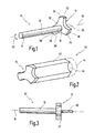
- a tool according to the invention is designated overall by the numeral 10.
- the tool 10 comprises a cylindrical shank 12 having a first end 14 and a second end 16.
- the tool 10 may with its first end 14 in a chuck of a Oszillationsantriebes (see. Fig. 4 ) are clamped.
- a cutting head 13 is provided, which has three outwardly projecting projections 22, 24, 26, which are offset at equal angular intervals of 120 ° to each other. Between adjacent projections 22, 24, 26, a recess 28, 30, 32 is formed in each case, which has a concave shape.
- the tool when it is attached with its first end 14 to an oscillating drive, are driven to oscillate about its longitudinal axis 18 back and forth.
- the oscillatory movement is preferably carried out at a high frequency between about 5,000 and 25,000 oscillations per minute and a small pivot angle between about 0.5 and 5 °.
- the entire machine can be gradually rotated about the longitudinal axis 18.
- the negative shape of the cutting head 13 predetermined by the preceding oscillation step is gradually increased into a cylindrical bore section which is used as the second bore section 44 in FIG Fig. 2 indicated by dashed lines.
- the second bore portion 44 results in an enlargement of the cross section of the bore to a fully cylindrical shape, provided that a rotation of at least 360 ° is realized.
- a bore 40 is thus produced which has a first bore section 42 and a second bore section 44, wherein 44 results at the transition between the first bore section 42 and the second bore section 44 undercuts 46.
- Fig. 1 described form of the cutting head 13 is merely exemplary in nature. It can thus be provided as many projections, which protrude radially outward with respect to the shaft 12. Furthermore, the shape of the projections can be modified in many ways. Also, the shape of the outer surfaces 34, 36, 38 in many ways adaptable to the particular circumstances. Finally, the recesses 28, 30, 32 may have the most varied shapes and sizes.
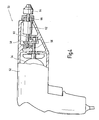
- the overrunning clutch can be determined so that the oscillatory drive 50 has two modes, namely a first mode in which the tool clamped therein is set in a reciprocating rotary oscillation about its longitudinal axis, and in a second mode, in the the tool is driven in a preferred direction of rotation with angular momentum.
- the in Fig. 4 shown oscillation drive 50 has a housing 52 in which an electric motor 54 is received.
- the motor shaft 56 of the electric motor 54 drives an oscillating device 58, which has approximately a pivoting fork, which cooperates with an eccentric.
- the oscillation device 58 By means of the oscillation device 58, the rotational movement of the motor shaft 56 is converted into a rotational pivoting movement of a shaft 60.
- a freewheel 62 is driven.
- This is the output side connected to a drive shaft 66 to which a tool holder 64, such as a chuck, for receiving a tool 10 or 10 'is provided.
- the freewheel 62 is switchable between a rigid drive and a freewheeling action.
- the oscillation movement of the shaft 60 is transmitted directly to the drive shaft 66.
- This mode allows the creation of the first bore portion 42 with the reciprocating rotary motion.
- the freewheel 62 is changed over, so that the oscillation movement of the shaft 60 is converted into angular momenta with a preferred direction (clockwise or anti-clockwise rotation).
- the second bore section can be produced in a particularly simple manner with the aid of the oscillation drive 50.
Landscapes
- Engineering & Computer Science (AREA)
- Mechanical Engineering (AREA)
- Processing Of Stones Or Stones Resemblance Materials (AREA)
- Drilling And Boring (AREA)
- Drilling Tools (AREA)
- Earth Drilling (AREA)
- Polishing Bodies And Polishing Tools (AREA)
Priority Applications (1)
| Application Number | Priority Date | Filing Date | Title |
|---|---|---|---|
| PL05026682T PL1674181T3 (pl) | 2004-12-21 | 2005-12-07 | Sposób i urządzenie do wykonania otworów wierconych |
Applications Claiming Priority (1)
| Application Number | Priority Date | Filing Date | Title |
|---|---|---|---|
| DE102004062858A DE102004062858A1 (de) | 2004-12-21 | 2004-12-21 | Verfahren und Vorrichtung zur Herstellung von Bohrungen |
Publications (3)
| Publication Number | Publication Date |
|---|---|
| EP1674181A2 EP1674181A2 (de) | 2006-06-28 |
| EP1674181A3 EP1674181A3 (de) | 2006-08-09 |
| EP1674181B1 true EP1674181B1 (de) | 2008-12-24 |
Family
ID=35659023
Family Applications (1)
| Application Number | Title | Priority Date | Filing Date |
|---|---|---|---|
| EP05026682A Not-in-force EP1674181B1 (de) | 2004-12-21 | 2005-12-07 | Verfahren und Vorrichtung zur Herstellung von Bohrungen |
Country Status (8)
| Country | Link |
|---|---|
| US (2) | US20060157284A1 (zh) |
| EP (1) | EP1674181B1 (zh) |
| JP (1) | JP4602239B2 (zh) |
| CN (1) | CN1792530B (zh) |
| AT (1) | ATE418411T1 (zh) |
| DE (2) | DE102004062858A1 (zh) |
| ES (1) | ES2317131T3 (zh) |
| PL (1) | PL1674181T3 (zh) |
Families Citing this family (5)
| Publication number | Priority date | Publication date | Assignee | Title |
|---|---|---|---|---|
| DE102008061271A1 (de) * | 2008-12-10 | 2010-06-24 | Emag Holding Gmbh | Vorrichtung zum Schleifen von Nocken einer Nockenwelle |
| US8365419B2 (en) | 2009-09-29 | 2013-02-05 | Robert Bosch Gmbh | Accessory attachment system for an oscillating power tool |
| US9217287B2 (en) * | 2011-08-02 | 2015-12-22 | Halliburton Energy Services, Inc. | Systems and methods for drilling boreholes with noncircular or variable cross-sections |
| DE102014101827A1 (de) | 2014-02-13 | 2015-08-13 | C. & E. Fein Gmbh | Bohrmaschine und Bohrwerkzeug hierfür |
| EP3085311B1 (en) * | 2015-04-21 | 2018-12-26 | Oticon Medical A/S | Indicator for installing a medical device |
Family Cites Families (26)
| Publication number | Priority date | Publication date | Assignee | Title |
|---|---|---|---|---|
| US1425402A (en) * | 1920-06-30 | 1922-08-08 | Mackenzie Philip | Combined drill and valve grinder |
| US1887372A (en) * | 1928-12-22 | 1932-11-08 | Cleveland Twist Drill Co | Cutting and forming tools, implements, and the like |
| DE540943C (de) * | 1930-03-18 | 1931-12-31 | Paul Harraser | Vorrichtung zum Bohren mehrkantiger Loecher, insbesondere fuer Holz |
| US4083351A (en) * | 1977-01-21 | 1978-04-11 | Harold Jack Greenspan | Fluted diamond drill |
| JPH01158196A (ja) * | 1987-12-14 | 1989-06-21 | Kubota Ltd | 掘削機 |
| JPH0347711A (ja) | 1989-04-12 | 1991-02-28 | Asahi Chem Ind Co Ltd | 繊維強化熱可塑性樹脂ペレット構造体 |
| JPH0739525Y2 (ja) * | 1989-09-11 | 1995-09-13 | 三京ダイヤモンド工業株式会社 | ドリル |
| DE4102794A1 (de) * | 1991-01-31 | 1992-08-06 | Hawera Probst Kg Hartmetall | Bohrwerkzeug |
| JP2926125B2 (ja) * | 1991-03-07 | 1999-07-28 | 東急建設株式会社 | 矩形シールド装置 |
| JPH0529629A (ja) | 1991-07-19 | 1993-02-05 | Mitsubishi Electric Corp | 電界効果型半導体装置 |
| JPH0529629U (ja) * | 1991-09-30 | 1993-04-20 | 豊田工機株式会社 | 電着リーマ工具 |
| JP3088537B2 (ja) * | 1991-12-11 | 2000-09-18 | 株式会社不二越 | 高硬度材の孔の仕上げ加工方法及び加工装置 |
| JPH0636768U (ja) * | 1992-10-17 | 1994-05-17 | 有限会社山本工業 | 砥 石 |
| DE4314799C2 (de) * | 1993-05-05 | 1995-04-13 | Fein C & E | Elektrowerkzeug |
| DE4344849A1 (de) | 1993-12-29 | 1995-07-06 | Fein C & E | Werkzeugmaschine |
| JPH09174170A (ja) * | 1995-12-22 | 1997-07-08 | Kanazawa Minami:Kk | 金属屋根板の軒先の孔明け工具、孔明け方法及び孔明け装置 |
| US5747953A (en) * | 1996-03-29 | 1998-05-05 | Stryker Corporation | Cordless, battery operated surical tool |
| DE19803439A1 (de) * | 1998-01-29 | 1999-08-05 | Sachse Hans E | Oszillierendes Knochenentnahmegerät |
| DE19815443C1 (de) * | 1998-04-07 | 1999-12-23 | Fein C & E | Schleifgerät |
| JP3671113B2 (ja) * | 1998-07-09 | 2005-07-13 | 本田技研工業株式会社 | 歯車用鍛造型の製造方法 |
| IL125766A (en) * | 1998-08-13 | 2002-12-01 | Iscar Ltd | The barrel of a tool and a rotating cutting head for placing on it in the form of a self-lining |
| JP2000107919A (ja) * | 1998-10-01 | 2000-04-18 | House Bm:Kk | ホールソーおよび孔開け工具 |
| US6652202B2 (en) * | 2000-01-03 | 2003-11-25 | Quick Turn Manufacturing, Llc | Drill bit apparatus and method of manufacture of same |
| JP3421661B2 (ja) * | 2001-05-11 | 2003-06-30 | 徳島県 | 放電加工装置および放電加工方法 |
| US20040156689A1 (en) * | 2003-02-07 | 2004-08-12 | Shen Shui Liang | Drill bit |
| US20090050682A1 (en) * | 2007-08-22 | 2009-02-26 | Jennifer Cole | E-Z BOP BOX TOP a re-closable box with a spout |
-
2004
- 2004-12-21 DE DE102004062858A patent/DE102004062858A1/de not_active Withdrawn
-
2005
- 2005-12-07 DE DE502005006316T patent/DE502005006316D1/de active Active
- 2005-12-07 ES ES05026682T patent/ES2317131T3/es active Active
- 2005-12-07 PL PL05026682T patent/PL1674181T3/pl unknown
- 2005-12-07 EP EP05026682A patent/EP1674181B1/de not_active Not-in-force
- 2005-12-07 AT AT05026682T patent/ATE418411T1/de active
- 2005-12-13 JP JP2005358430A patent/JP4602239B2/ja not_active Expired - Fee Related
- 2005-12-20 CN CN2005101326926A patent/CN1792530B/zh not_active Expired - Fee Related
- 2005-12-21 US US11/314,326 patent/US20060157284A1/en not_active Abandoned
-
2011
- 2011-01-10 US US12/987,634 patent/US8100197B2/en active Active
Also Published As
| Publication number | Publication date |
|---|---|
| CN1792530B (zh) | 2011-11-09 |
| US20110110738A1 (en) | 2011-05-12 |
| PL1674181T3 (pl) | 2009-06-30 |
| DE502005006316D1 (de) | 2009-02-05 |
| JP2006175593A (ja) | 2006-07-06 |
| US8100197B2 (en) | 2012-01-24 |
| JP4602239B2 (ja) | 2010-12-22 |
| EP1674181A2 (de) | 2006-06-28 |
| DE102004062858A1 (de) | 2006-08-10 |
| EP1674181A3 (de) | 2006-08-09 |
| ATE418411T1 (de) | 2009-01-15 |
| CN1792530A (zh) | 2006-06-28 |
| US20060157284A1 (en) | 2006-07-20 |
| ES2317131T3 (es) | 2009-04-16 |
Similar Documents
| Publication | Publication Date | Title |
|---|---|---|
| EP0432260B1 (de) | Vorrichtung zum führen einer innensäge zur osteotomie langer röhrenknochen | |
| EP1674181B1 (de) | Verfahren und Vorrichtung zur Herstellung von Bohrungen | |
| EP1753572A1 (de) | Verfahren, anker und bohrmaschine zur verankerung des ankers in einem ankergrund | |
| DE102004026675B3 (de) | Verfahren und Vorrichtung zum spanenden Bearbeiten rotationssymmetrischer Flächen eines Werkstückes | |
| EP2705928A1 (de) | Bohrmaschine und -Verfahren mit überlagerter oszillierenden Vorschubbewegung | |
| EP0656240B1 (de) | Bohrvorrichtung mit radial auslenkbarer Bohrspindel | |
| EP0937860A1 (de) | Bohr- und/oder Meisselwerkzeug | |
| DE2735368C2 (de) | Gesteinsbohrkrone mit einem Hartmetall-Bohrkopf | |
| EP1602428A1 (de) | Handgeführtes Elektrowerkzeug | |
| EP0304002B1 (de) | Bohrer für Handbohrmaschinen, Schraubbithalter und Verfahren zum Herstellen dieser Werkzeuge | |
| DE10311079A1 (de) | Bohrvorrichtung | |
| WO2021197696A1 (de) | Verfahren zur erzeugung einer werkstück-gewindebohrung | |
| EP0808696B1 (de) | Befestigungssystem und Verfahren zur Erstellung von Befestigungen | |
| DE102014101827A1 (de) | Bohrmaschine und Bohrwerkzeug hierfür | |
| DE2734111B2 (de) | Drehschlagbohrverfahren mit Wechsel der Drehrichtung des Bohrgestänges | |
| DE3629562C1 (en) | Drill for making a conical undercut in a predrilled cylindrical hole | |
| DE2323316C3 (de) | Drehantrieb in einer Einrichtung zum Herstellen von Gewindelöchern aus dem vollen Material | |
| DE2756706A1 (de) | Senkwerkzeug zum rueckwaertssenken | |
| DE3829216C2 (zh) | ||
| EP0195265B1 (de) | Werkzeug zur Herstellung hinterschnittener Bohrlöcher | |
| DE202018105582U1 (de) | Elektrohammer | |
| EP1574663A1 (de) | Handgeführtes Elektrowerkzeug | |
| EP1602839B1 (de) | Dübel zum Einsetzen in ein Bohrloch | |
| WO2018224214A1 (de) | Spannvorrichtung sowie ultraschall-bohrmaschine | |
| DE892735C (de) | Schraemmaschine |
Legal Events
| Date | Code | Title | Description |
|---|---|---|---|
| PUAI | Public reference made under article 153(3) epc to a published international application that has entered the european phase |
Free format text: ORIGINAL CODE: 0009012 |
|
| AK | Designated contracting states |
Kind code of ref document: A2 Designated state(s): AT BE BG CH CY CZ DE DK EE ES FI FR GB GR HU IE IS IT LI LT LU LV MC NL PL PT RO SE SI SK TR |
|
| AX | Request for extension of the european patent |
Extension state: AL BA HR MK YU |
|
| PUAL | Search report despatched |
Free format text: ORIGINAL CODE: 0009013 |
|
| AK | Designated contracting states |
Kind code of ref document: A3 Designated state(s): AT BE BG CH CY CZ DE DK EE ES FI FR GB GR HU IE IS IT LI LT LU LV MC NL PL PT RO SE SI SK TR |
|
| AX | Request for extension of the european patent |
Extension state: AL BA HR MK YU |
|
| 17P | Request for examination filed |
Effective date: 20070111 |
|
| 17Q | First examination report despatched |
Effective date: 20070215 |
|
| AKX | Designation fees paid |
Designated state(s): AT BE BG CH CY CZ DE DK EE ES FI FR GB GR HU IE IS IT LI LT LU LV MC NL PL PT RO SE SI SK TR |
|
| GRAP | Despatch of communication of intention to grant a patent |
Free format text: ORIGINAL CODE: EPIDOSNIGR1 |
|
| GRAS | Grant fee paid |
Free format text: ORIGINAL CODE: EPIDOSNIGR3 |
|
| GRAA | (expected) grant |
Free format text: ORIGINAL CODE: 0009210 |
|
| AK | Designated contracting states |
Kind code of ref document: B1 Designated state(s): AT BE BG CH CY CZ DE DK EE ES FI FR GB GR HU IE IS IT LI LT LU LV MC NL PL PT RO SE SI SK TR |
|
| REG | Reference to a national code |
Ref country code: GB Ref legal event code: FG4D Free format text: NOT ENGLISH |
|
| REG | Reference to a national code |
Ref country code: CH Ref legal event code: EP Ref country code: CH Ref legal event code: NV Representative=s name: TROESCH SCHEIDEGGER WERNER AG |
|
| REG | Reference to a national code |
Ref country code: IE Ref legal event code: FG4D Free format text: LANGUAGE OF EP DOCUMENT: GERMAN |
|
| REF | Corresponds to: |
Ref document number: 502005006316 Country of ref document: DE Date of ref document: 20090205 Kind code of ref document: P |
|
| REG | Reference to a national code |
Ref country code: SE Ref legal event code: TRGR |
|
| REG | Reference to a national code |
Ref country code: ES Ref legal event code: FG2A Ref document number: 2317131 Country of ref document: ES Kind code of ref document: T3 |
|
| PG25 | Lapsed in a contracting state [announced via postgrant information from national office to epo] |
Ref country code: LT Free format text: LAPSE BECAUSE OF FAILURE TO SUBMIT A TRANSLATION OF THE DESCRIPTION OR TO PAY THE FEE WITHIN THE PRESCRIBED TIME-LIMIT Effective date: 20081224 |
|
| PG25 | Lapsed in a contracting state [announced via postgrant information from national office to epo] |
Ref country code: FI Free format text: LAPSE BECAUSE OF FAILURE TO SUBMIT A TRANSLATION OF THE DESCRIPTION OR TO PAY THE FEE WITHIN THE PRESCRIBED TIME-LIMIT Effective date: 20081224 Ref country code: SI Free format text: LAPSE BECAUSE OF FAILURE TO SUBMIT A TRANSLATION OF THE DESCRIPTION OR TO PAY THE FEE WITHIN THE PRESCRIBED TIME-LIMIT Effective date: 20081224 Ref country code: LV Free format text: LAPSE BECAUSE OF FAILURE TO SUBMIT A TRANSLATION OF THE DESCRIPTION OR TO PAY THE FEE WITHIN THE PRESCRIBED TIME-LIMIT Effective date: 20081224 |
|
| REG | Reference to a national code |
Ref country code: PL Ref legal event code: T3 |
|
| REG | Reference to a national code |
Ref country code: IE Ref legal event code: FD4D |
|
| PG25 | Lapsed in a contracting state [announced via postgrant information from national office to epo] |
Ref country code: IE Free format text: LAPSE BECAUSE OF FAILURE TO SUBMIT A TRANSLATION OF THE DESCRIPTION OR TO PAY THE FEE WITHIN THE PRESCRIBED TIME-LIMIT Effective date: 20081224 Ref country code: EE Free format text: LAPSE BECAUSE OF FAILURE TO SUBMIT A TRANSLATION OF THE DESCRIPTION OR TO PAY THE FEE WITHIN THE PRESCRIBED TIME-LIMIT Effective date: 20081224 Ref country code: RO Free format text: LAPSE BECAUSE OF FAILURE TO SUBMIT A TRANSLATION OF THE DESCRIPTION OR TO PAY THE FEE WITHIN THE PRESCRIBED TIME-LIMIT Effective date: 20081224 Ref country code: BG Free format text: LAPSE BECAUSE OF FAILURE TO SUBMIT A TRANSLATION OF THE DESCRIPTION OR TO PAY THE FEE WITHIN THE PRESCRIBED TIME-LIMIT Effective date: 20090324 |
|
| PG25 | Lapsed in a contracting state [announced via postgrant information from national office to epo] |
Ref country code: PT Free format text: LAPSE BECAUSE OF FAILURE TO SUBMIT A TRANSLATION OF THE DESCRIPTION OR TO PAY THE FEE WITHIN THE PRESCRIBED TIME-LIMIT Effective date: 20090525 Ref country code: IS Free format text: LAPSE BECAUSE OF FAILURE TO SUBMIT A TRANSLATION OF THE DESCRIPTION OR TO PAY THE FEE WITHIN THE PRESCRIBED TIME-LIMIT Effective date: 20090424 Ref country code: CZ Free format text: LAPSE BECAUSE OF FAILURE TO SUBMIT A TRANSLATION OF THE DESCRIPTION OR TO PAY THE FEE WITHIN THE PRESCRIBED TIME-LIMIT Effective date: 20081224 |
|
| PG25 | Lapsed in a contracting state [announced via postgrant information from national office to epo] |
Ref country code: SK Free format text: LAPSE BECAUSE OF FAILURE TO SUBMIT A TRANSLATION OF THE DESCRIPTION OR TO PAY THE FEE WITHIN THE PRESCRIBED TIME-LIMIT Effective date: 20081224 |
|
| PG25 | Lapsed in a contracting state [announced via postgrant information from national office to epo] |
Ref country code: DK Free format text: LAPSE BECAUSE OF FAILURE TO SUBMIT A TRANSLATION OF THE DESCRIPTION OR TO PAY THE FEE WITHIN THE PRESCRIBED TIME-LIMIT Effective date: 20081224 |
|
| PLBE | No opposition filed within time limit |
Free format text: ORIGINAL CODE: 0009261 |
|
| STAA | Information on the status of an ep patent application or granted ep patent |
Free format text: STATUS: NO OPPOSITION FILED WITHIN TIME LIMIT |
|
| 26N | No opposition filed |
Effective date: 20090925 |
|
| BERE | Be: lapsed |
Owner name: C. & E. FEIN G.M.B.H. Effective date: 20091231 |
|
| PG25 | Lapsed in a contracting state [announced via postgrant information from national office to epo] |
Ref country code: MC Free format text: LAPSE BECAUSE OF NON-PAYMENT OF DUE FEES Effective date: 20100701 |
|
| PG25 | Lapsed in a contracting state [announced via postgrant information from national office to epo] |
Ref country code: GR Free format text: LAPSE BECAUSE OF FAILURE TO SUBMIT A TRANSLATION OF THE DESCRIPTION OR TO PAY THE FEE WITHIN THE PRESCRIBED TIME-LIMIT Effective date: 20090325 Ref country code: BE Free format text: LAPSE BECAUSE OF NON-PAYMENT OF DUE FEES Effective date: 20091231 |
|
| PG25 | Lapsed in a contracting state [announced via postgrant information from national office to epo] |
Ref country code: LU Free format text: LAPSE BECAUSE OF NON-PAYMENT OF DUE FEES Effective date: 20091207 |
|
| PG25 | Lapsed in a contracting state [announced via postgrant information from national office to epo] |
Ref country code: HU Free format text: LAPSE BECAUSE OF FAILURE TO SUBMIT A TRANSLATION OF THE DESCRIPTION OR TO PAY THE FEE WITHIN THE PRESCRIBED TIME-LIMIT Effective date: 20090625 |
|
| PG25 | Lapsed in a contracting state [announced via postgrant information from national office to epo] |
Ref country code: TR Free format text: LAPSE BECAUSE OF FAILURE TO SUBMIT A TRANSLATION OF THE DESCRIPTION OR TO PAY THE FEE WITHIN THE PRESCRIBED TIME-LIMIT Effective date: 20081224 |
|
| PG25 | Lapsed in a contracting state [announced via postgrant information from national office to epo] |
Ref country code: CY Free format text: LAPSE BECAUSE OF FAILURE TO SUBMIT A TRANSLATION OF THE DESCRIPTION OR TO PAY THE FEE WITHIN THE PRESCRIBED TIME-LIMIT Effective date: 20081224 |
|
| PGFP | Annual fee paid to national office [announced via postgrant information from national office to epo] |
Ref country code: ES Payment date: 20141111 Year of fee payment: 10 Ref country code: GB Payment date: 20141203 Year of fee payment: 10 Ref country code: CH Payment date: 20141212 Year of fee payment: 10 Ref country code: SE Payment date: 20141211 Year of fee payment: 10 |
|
| PGFP | Annual fee paid to national office [announced via postgrant information from national office to epo] |
Ref country code: AT Payment date: 20141125 Year of fee payment: 10 Ref country code: PL Payment date: 20141113 Year of fee payment: 10 Ref country code: NL Payment date: 20141210 Year of fee payment: 10 Ref country code: FR Payment date: 20141208 Year of fee payment: 10 |
|
| PGFP | Annual fee paid to national office [announced via postgrant information from national office to epo] |
Ref country code: IT Payment date: 20141203 Year of fee payment: 10 |
|
| REG | Reference to a national code |
Ref country code: CH Ref legal event code: PL |
|
| REG | Reference to a national code |
Ref country code: SE Ref legal event code: EUG |
|
| REG | Reference to a national code |
Ref country code: AT Ref legal event code: MM01 Ref document number: 418411 Country of ref document: AT Kind code of ref document: T Effective date: 20151207 |
|
| GBPC | Gb: european patent ceased through non-payment of renewal fee |
Effective date: 20151207 |
|
| PG25 | Lapsed in a contracting state [announced via postgrant information from national office to epo] |
Ref country code: SE Free format text: LAPSE BECAUSE OF NON-PAYMENT OF DUE FEES Effective date: 20151208 |
|
| REG | Reference to a national code |
Ref country code: NL Ref legal event code: MM Effective date: 20160101 |
|
| REG | Reference to a national code |
Ref country code: FR Ref legal event code: ST Effective date: 20160831 |
|
| PG25 | Lapsed in a contracting state [announced via postgrant information from national office to epo] |
Ref country code: CH Free format text: LAPSE BECAUSE OF NON-PAYMENT OF DUE FEES Effective date: 20151231 Ref country code: LI Free format text: LAPSE BECAUSE OF NON-PAYMENT OF DUE FEES Effective date: 20151231 Ref country code: GB Free format text: LAPSE BECAUSE OF NON-PAYMENT OF DUE FEES Effective date: 20151207 Ref country code: NL Free format text: LAPSE BECAUSE OF NON-PAYMENT OF DUE FEES Effective date: 20160101 |
|
| PG25 | Lapsed in a contracting state [announced via postgrant information from national office to epo] |
Ref country code: AT Free format text: LAPSE BECAUSE OF NON-PAYMENT OF DUE FEES Effective date: 20151207 Ref country code: FR Free format text: LAPSE BECAUSE OF NON-PAYMENT OF DUE FEES Effective date: 20151231 |
|
| PG25 | Lapsed in a contracting state [announced via postgrant information from national office to epo] |
Ref country code: IT Free format text: LAPSE BECAUSE OF NON-PAYMENT OF DUE FEES Effective date: 20151207 |
|
| PG25 | Lapsed in a contracting state [announced via postgrant information from national office to epo] |
Ref country code: PL Free format text: LAPSE BECAUSE OF NON-PAYMENT OF DUE FEES Effective date: 20151207 |
|
| PG25 | Lapsed in a contracting state [announced via postgrant information from national office to epo] |
Ref country code: ES Free format text: LAPSE BECAUSE OF NON-PAYMENT OF DUE FEES Effective date: 20151208 |
|
| PGFP | Annual fee paid to national office [announced via postgrant information from national office to epo] |
Ref country code: DE Payment date: 20171129 Year of fee payment: 13 |
|
| REG | Reference to a national code |
Ref country code: ES Ref legal event code: FD2A Effective date: 20180705 |
|
| REG | Reference to a national code |
Ref country code: DE Ref legal event code: R119 Ref document number: 502005006316 Country of ref document: DE |
|
| PG25 | Lapsed in a contracting state [announced via postgrant information from national office to epo] |
Ref country code: DE Free format text: LAPSE BECAUSE OF NON-PAYMENT OF DUE FEES Effective date: 20190702 |