EP1673553B1 - Epicyclic gear system - Google Patents
Epicyclic gear system Download PDFInfo
- Publication number
- EP1673553B1 EP1673553B1 EP04794168A EP04794168A EP1673553B1 EP 1673553 B1 EP1673553 B1 EP 1673553B1 EP 04794168 A EP04794168 A EP 04794168A EP 04794168 A EP04794168 A EP 04794168A EP 1673553 B1 EP1673553 B1 EP 1673553B1
- Authority
- EP
- European Patent Office
- Prior art keywords
- pin
- carrier
- gear
- head
- raceways
- Prior art date
- Legal status (The legal status is an assumption and is not a legal conclusion. Google has not performed a legal analysis and makes no representation as to the accuracy of the status listed.)
- Expired - Lifetime
Links
- 238000005096 rolling process Methods 0.000 claims description 7
- OKTJSMMVPCPJKN-UHFFFAOYSA-N Carbon Chemical group [C] OKTJSMMVPCPJKN-UHFFFAOYSA-N 0.000 description 7
- 229910052799 carbon Inorganic materials 0.000 description 6
- 238000000576 coating method Methods 0.000 description 6
- 239000000463 material Substances 0.000 description 6
- 229910000831 Steel Inorganic materials 0.000 description 5
- 239000011248 coating agent Substances 0.000 description 5
- 230000001419 dependent effect Effects 0.000 description 5
- 101800002712 p27 Proteins 0.000 description 5
- 239000010959 steel Substances 0.000 description 5
- 239000000969 carrier Substances 0.000 description 4
- 230000036316 preload Effects 0.000 description 4
- 239000002184 metal Substances 0.000 description 3
- 238000000034 method Methods 0.000 description 3
- 238000010438 heat treatment Methods 0.000 description 2
- 230000000873 masking effect Effects 0.000 description 2
- 239000002245 particle Substances 0.000 description 2
- 229910000851 Alloy steel Inorganic materials 0.000 description 1
- 239000004215 Carbon black (E152) Substances 0.000 description 1
- 229910001209 Low-carbon steel Inorganic materials 0.000 description 1
- 238000005452 bending Methods 0.000 description 1
- 230000005540 biological transmission Effects 0.000 description 1
- 238000005255 carburizing Methods 0.000 description 1
- 238000005234 chemical deposition Methods 0.000 description 1
- 230000000295 complement effect Effects 0.000 description 1
- 230000003467 diminishing effect Effects 0.000 description 1
- 230000000694 effects Effects 0.000 description 1
- 229930195733 hydrocarbon Natural products 0.000 description 1
- 150000002430 hydrocarbons Chemical class 0.000 description 1
- 238000005461 lubrication Methods 0.000 description 1
- 239000011159 matrix material Substances 0.000 description 1
- 238000005259 measurement Methods 0.000 description 1
- 230000035515 penetration Effects 0.000 description 1
- 238000005240 physical vapour deposition Methods 0.000 description 1
Images


Classifications
-
- F—MECHANICAL ENGINEERING; LIGHTING; HEATING; WEAPONS; BLASTING
- F16—ENGINEERING ELEMENTS AND UNITS; GENERAL MEASURES FOR PRODUCING AND MAINTAINING EFFECTIVE FUNCTIONING OF MACHINES OR INSTALLATIONS; THERMAL INSULATION IN GENERAL
- F16H—GEARING
- F16H1/00—Toothed gearings for conveying rotary motion
- F16H1/28—Toothed gearings for conveying rotary motion with gears having orbital motion
- F16H1/2809—Toothed gearings for conveying rotary motion with gears having orbital motion with means for equalising the distribution of load on the planet gears
- F16H1/2836—Toothed gearings for conveying rotary motion with gears having orbital motion with means for equalising the distribution of load on the planet gears by allowing limited movement of the planet gears relative to the planet carrier or by using free floating planet gears
-
- F—MECHANICAL ENGINEERING; LIGHTING; HEATING; WEAPONS; BLASTING
- F16—ENGINEERING ELEMENTS AND UNITS; GENERAL MEASURES FOR PRODUCING AND MAINTAINING EFFECTIVE FUNCTIONING OF MACHINES OR INSTALLATIONS; THERMAL INSULATION IN GENERAL
- F16C—SHAFTS; FLEXIBLE SHAFTS; ELEMENTS OR CRANKSHAFT MECHANISMS; ROTARY BODIES OTHER THAN GEARING ELEMENTS; BEARINGS
- F16C19/00—Bearings with rolling contact, for exclusively rotary movement
- F16C19/22—Bearings with rolling contact, for exclusively rotary movement with bearing rollers essentially of the same size in one or more circular rows, e.g. needle bearings
- F16C19/34—Bearings with rolling contact, for exclusively rotary movement with bearing rollers essentially of the same size in one or more circular rows, e.g. needle bearings for both radial and axial load
- F16C19/38—Bearings with rolling contact, for exclusively rotary movement with bearing rollers essentially of the same size in one or more circular rows, e.g. needle bearings for both radial and axial load with two or more rows of rollers
- F16C19/383—Bearings with rolling contact, for exclusively rotary movement with bearing rollers essentially of the same size in one or more circular rows, e.g. needle bearings for both radial and axial load with two or more rows of rollers with tapered rollers, i.e. rollers having essentially the shape of a truncated cone
- F16C19/385—Bearings with rolling contact, for exclusively rotary movement with bearing rollers essentially of the same size in one or more circular rows, e.g. needle bearings for both radial and axial load with two or more rows of rollers with tapered rollers, i.e. rollers having essentially the shape of a truncated cone with two rows, i.e. double-row tapered roller bearings
- F16C19/386—Bearings with rolling contact, for exclusively rotary movement with bearing rollers essentially of the same size in one or more circular rows, e.g. needle bearings for both radial and axial load with two or more rows of rollers with tapered rollers, i.e. rollers having essentially the shape of a truncated cone with two rows, i.e. double-row tapered roller bearings in O-arrangement
-
- F—MECHANICAL ENGINEERING; LIGHTING; HEATING; WEAPONS; BLASTING
- F16—ENGINEERING ELEMENTS AND UNITS; GENERAL MEASURES FOR PRODUCING AND MAINTAINING EFFECTIVE FUNCTIONING OF MACHINES OR INSTALLATIONS; THERMAL INSULATION IN GENERAL
- F16C—SHAFTS; FLEXIBLE SHAFTS; ELEMENTS OR CRANKSHAFT MECHANISMS; ROTARY BODIES OTHER THAN GEARING ELEMENTS; BEARINGS
- F16C33/00—Parts of bearings; Special methods for making bearings or parts thereof
- F16C33/30—Parts of ball or roller bearings
- F16C33/58—Raceways; Race rings
- F16C33/60—Raceways; Race rings divided or split, e.g. comprising two juxtaposed rings
- F16C33/605—Raceways; Race rings divided or split, e.g. comprising two juxtaposed rings with a separate retaining member, e.g. flange, shoulder, guide ring, secured to a race ring, adjacent to the race surface, so as to abut the end of the rolling elements, e.g. rollers, or the cage
-
- F—MECHANICAL ENGINEERING; LIGHTING; HEATING; WEAPONS; BLASTING
- F16—ENGINEERING ELEMENTS AND UNITS; GENERAL MEASURES FOR PRODUCING AND MAINTAINING EFFECTIVE FUNCTIONING OF MACHINES OR INSTALLATIONS; THERMAL INSULATION IN GENERAL
- F16H—GEARING
- F16H57/00—General details of gearing
- F16H57/08—General details of gearing of gearings with members having orbital motion
- F16H57/082—Planet carriers
-
- F—MECHANICAL ENGINEERING; LIGHTING; HEATING; WEAPONS; BLASTING
- F16—ENGINEERING ELEMENTS AND UNITS; GENERAL MEASURES FOR PRODUCING AND MAINTAINING EFFECTIVE FUNCTIONING OF MACHINES OR INSTALLATIONS; THERMAL INSULATION IN GENERAL
- F16C—SHAFTS; FLEXIBLE SHAFTS; ELEMENTS OR CRANKSHAFT MECHANISMS; ROTARY BODIES OTHER THAN GEARING ELEMENTS; BEARINGS
- F16C2240/00—Specified values or numerical ranges of parameters; Relations between them
- F16C2240/40—Linear dimensions, e.g. length, radius, thickness, gap
- F16C2240/70—Diameters; Radii
- F16C2240/80—Pitch circle diameters [PCD]
- F16C2240/82—Degree of filling, i.e. sum of diameters of rolling elements in relation to PCD
- F16C2240/84—Degree of filling, i.e. sum of diameters of rolling elements in relation to PCD with full complement of balls or rollers, i.e. sum of clearances less than diameter of one rolling element
-
- F—MECHANICAL ENGINEERING; LIGHTING; HEATING; WEAPONS; BLASTING
- F16—ENGINEERING ELEMENTS AND UNITS; GENERAL MEASURES FOR PRODUCING AND MAINTAINING EFFECTIVE FUNCTIONING OF MACHINES OR INSTALLATIONS; THERMAL INSULATION IN GENERAL
- F16C—SHAFTS; FLEXIBLE SHAFTS; ELEMENTS OR CRANKSHAFT MECHANISMS; ROTARY BODIES OTHER THAN GEARING ELEMENTS; BEARINGS
- F16C2361/00—Apparatus or articles in engineering in general
- F16C2361/61—Toothed gear systems, e.g. support of pinion shafts
Definitions
- This invention relates in general to gear systems and, more particularly, to an epicyclic gear system:
- the typical epicyclic or planetary gear system basically has a sun gear provided with external teeth, a ring gear provided with internal teeth, and several planet gears located between the sun and ring gears and having external teeth which mesh with the teeth on the sun and ring gears.
- the typical system has a carrier to which the planet gears are coupled. Either the sun gear, the ring gear, or the carrier is held fast, while power is delivered to and taken from the remaining two components, and thus power is transferred through the planetary system with a change in angular velocity and an inverse change torque.
- the sun and ring gears for all intents and purposes share the same axis - a central axis - while the planet gears revolve about radially offset axes that are parallel to the central axis - or at least they should be. Often the offset axes and the central axis are not parallel, and as a consequence the planet gears skew slightly between sun and ring gears. This causes excessive wear along the teeth of the planet, sun and ring gears, generates friction and heat, and renders the entire system overly noisy.
- Another type of epicyclic gear system uses a single flange carrier and a double cantilever arrangement at the pins for the planetary gears to insure that the planet gears and the sun and ring gears remain properly meshed.
- the single carrier flange is offset axially from planet gears, and the carrier pins project from that flange into, and indeed through, the planet gears.
- Each carrier pin has one end anchored in the carrier flange and at its other end is fitted within a sleeve which returns back over the pin, yet is spaced radially from the pin, to support the planet gear.
- US Patent 3,303,713 to R J Hicks shows a double cantilevered arrangement.
- an antifriction bearing is fitted between the sleeve and the planet gear. But antifriction bearings consume space, masking the planet gears excessively large in diameter, which in turn makes the entire gear system too large and heavy.
- the carrier pin has a groove located between its shank and its head so that the groove facilitates flexure of the carrier pin immediately before its head.
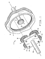
- an epicyclic gear system A ( Fig. 1 ), which is in effect a planetary transmission, has a sun gear 2, a ring gear 4 which surrounds the sun gear 2, and planetary gears 6 located between and engaged with the sun gear 2 and ring gear 4.
- the gear system A includes a carrier 8 on which the planet gears 6 rotate.
- the typical epicylic gear system has a sun gear, a ring gear, planet gears, and a carrier, but the gear system A is highly compact and for its size has a greater power density.
- the planet gears 6 mesh better with the sun gear 2 and ring gear 6, causing less wear, diminishing friction, and reducing noise.
- the gear system A has a central axis X.
- the sun gear 2 lies along the axis X with its center being the axis X. Thus, should it rotate, it will rotate about the axis X. It has external teeth 10 and is attached to a shaft 12 or some other supporting structure.
- the ring gear 4 surrounds the sun gear 2, with which it is concentric and thus shares the axis X. It is attached to a housing 14 or some other structure which may or may not rotate. Should it rotate, it will rotate about the axis X. It has internal teeth 16.
- the planet gears 6 occupy the annular space between the sun gear 2 and ring gear 4 and have external teeth 18 which mesh with the teeth 10 of the sun gear 2 and the teeth 16 of the ring gear 4. They rotate about axes Y that are offset from, yet parallel to, the central axis X.
- Each planet gear 6 has ( Figs. 2 & 3 ) tapered raceways 20 and 22 which are presented inwardly toward its axis Y and taper downwardly toward an intervening surface between the small ends of the raceways 20 and 22.
- the large ends of the raceways 20 and 22 open out of the gear 6 at end faces 26 and 28 which extend out to the teeth 18 and may be squared off with respect to the axis Y.
- the carrier 8 is attached to another shaft 30 ( Fig. 1 ) or other structure, and has its center along the axis X. Should it rotate, it will rotate about the axis X.
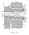
- the carrier 8 includes a carrier flange 32 and carrier pins 34 ( Fig. 2 ) which project all in the same direction from the flange 32, there being one pin 34 for each planet gear 6. More specifically, the carrier flange 32 lies opposite the end faces 26 of the planet gears 6, while the pins 34 project into the gears 6 to establish the axes Y about which the gears 6 rotate.
- the carrier flange 32 contains bores 36, with each pin 34 at one of its ends being fitted into one of the bores 36 with a interference fit and secured by a weld 38 at the very end of the pin 34 or otherwise attached firmly to the flange 32.
- the pins 34 have fixed ends which are anchored in the carrier flange 32 and free ends located remote from the carrier flange 32.
- each pin 34 has ( Figs. 2 & 3 ) a shank 40 at and leading away from its fixed end, a head 42 at its free end, and an intervening segment 44 forming a groove 46 between the shank 40 and head 42.
- the shank 40 typically projects beyond the carrier flange 32 a distance equal to or slightly less than the length of the groove 46. It extends out of one of the bores 36 of the flange 32 and into the planet gear 6 for the pin 34 and has a cylindrical surface of uniform diameter.
- the head 42 also has a cylindrical surface of uniform diameter, and that diameter may be slightly greater than the diameter of the shank 40. While the head 42 may be somewhat shorter than the shank 40, it still is long enough to lie partially within the planet gear 6.
- the intervening segment 44 also possesses a cylindrical surface of uniform diameter, except at its ends where it merges into the shank 40 and the head 42 at fillets 48. That diameter, of course, is less than the diameters of the shank 40 and head 42.
- each bearing 50 includes ( Figs. 2 & 3 ) the tapered raceways 20 and 22 on its planet gear 6.
- Each also includes an inner race 52 which is mounted on the head 42 of its pin 34 and projects over the pin 34 and into the gear 6.
- the inner race 52 includes a unitary race sleeve 54 and a separately formed rib ring 56 at one end of the sleeve 54.
- each bearing 50 has tapered rollers 58 organized in two rows, one along the raceway 20 and the other along the raceway 22. The rollers 58 surround the inner race 52.
- Each carrier pin 34 being anchored in the carrier flange 32 at its fixed end and otherwise projecting beyond the flange 32, is cantilevered from the flange 32.
- the race sleeve 54 that surrounds the pin 34 is fitted to the head 42 at opposite or free end of the pin 34 and doubles back over the pin 34, so that the sleeve 54 and the inner race 52 of which it is apart is cantilevered from the free end of the pin 34.
- the race sleeve 54 has a through bore 60, which at its one end receives the enlarged head 42 on the pin 34.
- the raceway 64 is located farthest from the head 42, while the raceway 66 is located generally around the head 42, with its small diameter end and the beginning of the head 42 being at generally the same axial location.
- the raceway 64 is presented toward the raceway 20 on the gear 6 and tapers in the same direction, whereas the raceway 66 is presented toward the raceway 22 on the gear 6 and tapers in the same direction as that raceway.
- the two raceways 64 and 66 like the raceways 20 and 22, taper downwardly toward each other.
- the intervening surface 67 is larger than the small ends of the raceways 64 and 66 and enhances the rigidity of the sleeve 54.
- the race sleeve 54 has a thrust rib 68 which is formed as an integral part of the sleeve 54. It projects axially slightly beyond the end face 26 of the gear 6 and radially to provide a rib face along the large end of the raceway 20.
- the other raceway 66 at its large end merges into a short cylindrical surface 70 of no greater diameter.
- the surface 70 leads out to a rabbet in the opposite end of the sleeve 54, that rabbet being formed by a cylindrical end surface 72 of lesser diameter and a shoulder 74 located between the two cylindrical surfaces 70 and 72.
- the rib ring 56 fits over the cylindrical surface 72 and against the shoulder 74. It projects radially outwardly past the other cylindrical surface 70 where it is provided with a rib 76 ( Fig. 2 ) which projects axially over the cylindrical surface 70 to present a rib face at the large end of the raceway 66.
- the opposite ends of the rib ring 56 and the end face on the head 42 of the carrier pin 34 are generally flush, and here the rib ring 56 is joined to the sleeve 54 along another circular weld 78.
- Both the race sleeve 54 and the rib ring 56 are formed from a low carbon bearing grade steel which is case carburized. Then the sleeve 54 may be ground along its end face out of which the rabbet opens and likewise the rib ring 56 may be ground along its corresponding end face, this to remove the hard case and expose the lower carbon core beneath it. Only after the hard case is removed in these areas, are the circular welds 62 and 78 made. On the other hand, one may mask these areas during the carburizing process to prevent carbon penetration, and thus eliminate the need for subsequent material removal.
- the tapered rollers 58 occupy the annular space between the gear 6 and the inner race 52. Here they are organized in two rows - one between the raceways 20 and 64 and the other between the raceways 22 and 66.
- the rollers 58 that are between the raceways 20 and 64 have their tapered side faces in contact with those raceways - there being generally line contact - and their large end faces against the face of the integral thrust rib 68.
- the rollers 58 that lie between the raceways 22 and 66 along their tapered side faces are generally in line contact with those raceways, and along their large end faces contact the face of the rib 76 on the rib ring 56.
- the rollers 58 of each row are on apex, meaning that the conical envelopes in which their side faces lie have their apices at a common point along the axis Y.
- the bearing 50 is preferably set to light preload, so no clearances exist between the raceways 20 and 64 and their rollers 58 and the raceways 22 and 66 and their rollers 58, and this is perhaps best achieved by grinding a surface of the rib ring 56 so as to control the axial position of the rib face for the rib 76 on the ring 56.
- the bearing 50 may be set with a slight end play, in which event clearances will exist in it.
- a cage may separate the rollers 58 of that row, so that they do not contact each other. But the cage may be eliminated to increase the load capacity of the bearing 50 and thereby make the gear system A even more compact.
- bearing 50 operates without a cage in its rows its rollers 58
- adjacent rollers 58 can contact each other along their tapered side faces.
- the rollers 58 along at least their tapered side faces should have a tribological coating that retards adhesion or at least every other roller 58 should have such a coating in it. Actually, a coating is applied only when speeds, loads, and lubrication are such that metal adhesion becomes possible.
- One suitable coating includes particles of noncrystalline metal carbide and an amorphous hydrocarbon matrix in which the particles are embedded.
- the tribological coating may be applied to the rollers 70 by physical vapor deposition, by chemical deposition, or by a combination of the two.
- U.S. patent application 10/114,832, filed 2 April 2002 for the invention of G. Doll and G. Fox entitled “Full Complement Antifriction Bearing", which invention is assigned to The Timken Company, discloses other tribological coatings, which will suffice for the rollers 70, and procedures for applying them. That application is incorporated herein by reference.
- the assembly of the gear system A begins with the carrier 8, particularly the pin 34 and the race sleeve 54 of the inner race 52.
- the head 42 of the pin 34 is forced into the sleeve 54 from the ground end of the sleeve 54 until the end face of the head 42 is flush with ground end face of the sleeve 42.
- rollers 58 are installed along the raceway 64 of the race sleeve 54 to provide one row of rollers 58.
- the gear 6 is advanced over the sleeve 54 with its end face 26 leading. Its raceway 20 comes against the row of tapered rollers 58 that exists around the raceway 64.
- rollers 58 By rotating the gear 6 relative to the sleeve 54, the rollers 58 along their side faces seat along the raceways 20, 64 and further move up those raceways until their large end faces seat against the face of the integral thrust rib 68. This leaves the remaining raceways 22 and 66 exposed. More rollers 58 are installed between these raceways 22 and 26. With the rollers 58 of this row seated along the raceways 22 and 66, measurements are taken to determine the distance between the large end faces of those rollers 58 and a reference surface on the race sleeve 54. A rib ring 56 is selected having a rib 76 which positions the rollers 58 such that the bearing 50 has the desired preload or clearance in it.
- the rib ring 56 is installed over the cylindrical surface 72 on the race sleeve 54 and against the shoulder 74. While the rib ring 56 is held against the shoulder 74, the weld 78 is made, and the weld 62 may be made at this time as well. This completes the assembly of the bearing 50.
- each bore 36 in the flange 32 is fitted with a carrier pin 34 that supports a planet gear 6 and bearing 50 installed on the pin 34 in the same manner.
- the carrier 8 complete, its planet gears 6 are fitted around and engaged with the sun gear 2 and also fitted into and engaged with the ring gear 4.
- the groove 46 in the pin 34 facilitates the flexure of the pin 34 immediately before its head 42, and this enables the inner race 52 to achieve the correct deflection without extending the pin 34 and inner race excessively beyond the end face 28 of the planet gear 6.
- the two deflections afforded by the double cantilever enables the planet gears 6 to be shortened and the groove 46 prevents excessive projection of the pin 34 and inner race 52 beyond the gear 6.
- the presence of the outer raceways 20 and 22 on the gear 65 itself and the inner raceways on the race sleeve 54 which is attached directly to the pin 34 further contributes to the compactness of the system A.
- the carrier pin 34 when provided with the groove 46, operates most effectively when the following dimensional relationships exist for a pin 34 formed from medium carbon, heat treated steel:
- the geometry of the groove 46 is dependent upon the required radial deflection for improved load sharing of the planet gears 6 with the sun gear 2 and ring gear 4.
- the nominal deflection of the pin 34 along the axis Y should be greater than the backlash between the gears 2, 4 and 6 in the epicyclic system A under nominal loading, this to insure that the load is equalized among the planet gears 6 and over the widths of those gears 6.
- Another carrier 80 ( Fig. 4 ) likewise establishes axes Y about which planet gears 6 revolve, and it also has a carrier flange 32 provided with bores 36. However, the gears 6 rotate on modified carrier pins 82 and modified inner races 84.
- Each pin 82 has a shank 40 and an intervening segment 44 beyond the shank 40 where it creates a groove 46 in the pin 82. Beyond the segment 44 and groove 46 the pin 82 has a modified head 86 provided with a large diameter surface 88 immediately beyond the groove 46 and a small diameter surface 90 extended beyond the large diameter surface 88 at a shoulder 92. The small diameter surface 90 leads out of the end of the pin 82.
- the inner race 84 for each pin 82 has in its race sleeve 54 an elongated bore 94 which at one end opens out of the race sleeve 54 through the thrust rib 68 and at its other end opens into a short reduced bore 96 which opens out of an end face 98 at the opposite end of the sleeve 54.
- the two bores 94 and 96 are separated by a shoulder 100.
- the head 86 of the pin 82 fits through the elongated bore 94, there being an interference fit between the large diameter surface 88 of the head 86 and the surface of the bore 94.
- the head 86, at its small diameter surface 90 projects through the reduced bore 96 and beyond the end face 98 of the race sleeve 54. Indeed, the head 86 of the pin 82 is advanced through the elongated bore 94 of the race sleeve 54 until its shoulder 92 comes against the shoulder 100 in the race sleeve 54.
- the modified inner race 84 has a modified rib ring 102 that fits around the small diameter surface 90 on the head 86 with an interference fit and bears against the end face 98.
- the rib ring 102 has a rib 104 which projects toward the integral thrust rib 68 and beyond the end face 98.
- the rib ring 102 is attached to the head 86 along a circular weld 106.
- the race sleeve 54 for the modified inner race 84 has tapered raceways 64 and 66 which lead up to the thrust rib 68 and rib 104, respectively.
- One row of tapered rollers 58 lies between the raceway 64 on the inner race 84 and the raceway 20 in the patent gear 6 and another row of tapered rollers 58 lies between the raceways 22 and 66, all to form a bearing 108 that is set to preload.
- the race sleeve 54 of the modified inner race 84 is formed from high carbon bearing grade steel that has been through hardened.
- the rib ring 102 is formed from low carbon bearing grade steel which has been case carburized. However, the case does not exist at the outer end of the race 84, it having been removed by grinding or, by reason of masking, having never formed, so that the weld 106 is made in the low carbon steel.
- Still another carrier 110 ( Fig. 5 ) is similar to the carriers 8 and 30 in that it supports planet gears 6 that rotate on bearings 50 including inner races 52 or 84. But the carrier 110 has a grooved pin 112 that differs somewhat from the grooved pins 34 and 82 of the carriers 8 and 30.
- the pin 112 has a shank 114 that lies entirely or almost entirely within the bore 36 of the carrier flange 32. Typically, the length of the shank 114 is equal to or less than the diameter of the carrier bore 36.
- the pin 112 also has a head 116 that fits within the through bore 60 of the race sleeve 54, to which it is secured by a weld 62 or 106. Between its shank 114 and its head 116, the pin 112 has a reduced intermediate segment 118 formed by a conical surface 120 and a cylindrical surface 122. The surfaces 120 and 122 produce the groove 46 in the pin 112.
- the conical surface 120 at its large end possesses a diameter equal to that of the shank 112 and here merges with the shank at a fillet 124.
- the surface 120 tapers downwardly away from the shank 114 and at its small end merges with the cylindrical surface 122 along another fillet 124.
- the cylindrical surface 122 extends toward the head 42 or 84, into which it merges along still another fillet 126.
- the section having the cylindrical surface 122 facilitates flexure circumferentially with respect to the axis X of the gear system A, whereas the section having the conical surface 120 facilitates flexure radially with respect to the axis X.
- the length of the conical surface 120 measured along the axis Y should be greater than one-half the distance between the faces of the thrust rib 68 and the rib ring 76.
- the length of the cylindrical surface 122, measured along the axis X, is typically one-half or less the length of the length of the conical surface 120, likewise measured along the axis X.
- the fillets 124 and 126 reduce stress concentrations associated with abrupt changes in diameter.
- the geometry of the intermediate segment 118, with its conical surface 120 and cylindrical surface 120 and fillets 124 and 126, is dependent upon the required radial deflection for improved load sharing of the planet gear 6 with the sun gear 2 and the ring gear 4.
- the nominal deflection of the pin 112 along the axis Y should be greater than the backlash between the gears 2, 4 and 6 in the epicyclic system. Under nominal loading, this to insure that the load is equalized among the planet gears 6 and over the widths of those gears 6.
- the fillet radius 124 values are related to stress level capacity of the planet carrier 32 at the face of the carrier flange 32 from which the pin 112 emerges as well as the yield strength limit of the pin 112.
- Yet another carrier 130 ( Fig. 6 ) is similar to the carriers 8, 30 and 110 in that it supports planet gears 6 that rotate on bearings 50, but the bearing 50 for each has a somewhat different inner race 132 which fits over and accommodates a different carrier pin 134.
- the inner race 132 and carrier pin 134 are configured such that the pin 134 experiences generally uniform stress between the flange 32 and that portion of the inner race 132 in which the pin 134 is received and anchored. This enables the pin 134 to have a minimum cross section.
- the pin 134 first, it has at one end a cylindrical shank 136 which is anchored, almost entirely, within the bore 36 and at its opposite end a cylindrical head 138 which is essentially the same diameter as the shank 136. Between the shank 136 and the head 138 the pin 134 has an intervening portion 140 formed from two approximately conical surfaces 142 which taper downwardly toward each other and merge at a fillet 144. The conical surfaces 142 and fillet 144 provide the carrier pin 134 with an annular groove 146.
- the inner race 132 includes a race sleeve 150 and a rib ring 152.
- the race sleeve 150 has through bore 60 where it receives the pin 134. It also has the two raceways 64 and 66 as well as the integral intervening surface 67 and rib ring 68. It also has the cylindrical surface 72 that leads away from the large end of the raceway 66 at a reduced diameter.
- the rib ring 152 fits over the cylindrical surface 72 of the race sleeve 150 and is joined to the race sleeve 150 at the weld 78. It has the rib 76 against which the large ends of the rollers 58 along it bear.
- the race sleeve 150 fits over the head 138 of the carrier pin 130 with an interference fit and is attached to the carrier pin 130 at a weld 62. It extends over the groove 146 where it is spaced from the intervening portion 140 of the pin 134, and at its opposite end is beveled so as to remain spaced from the underlying conical surface 142 - indeed, for enough to permit the race sleeve 150 to deflect radially with respect to pin 134.
- the head 138 lies axially beyond the face of the rib 76 on the rib ring 152 so that it does not underlie the raceway 66.
- the carrier 130 operates most effectively when the pin 134 is formed from median carbon, heat treated steel and flowing relationships exist:
- the geometry of the intervening portion 140 is dependent upon the required radial deflection for improved ioad sharing of the planet gears 6 with the sun gear 2 and ring gear 4.
- the nominal deflection of the pin 134 along the axis Y should be greater than the backlash between the gears 2, 4 and 6 in the epicyclic system A under nominal loading, this to insure that the load is equalized among the planet gears 6 and over the widths of those gears 6.
- the geometry of the intervening portion is obtained by solving the equation below for (D( x )) when given a stress level (VM), a load (P), and an active pin length (L 1 ).
- the stress level (VM), load (P), and pin length (L 1 ) are defined as constant and the pin diameter (D( x )) becomes variable.
- VM Von Mises Stress
- L 1 Active pin length
- X Distance from the end of the intervening portion 140
- D( x ) Pin diameter at a given distance X
- V ⁇ M x 2 P ⁇ L 1 - x - P ⁇ L 1 2 ⁇ ⁇ D x 2 32 2 + 3 ⁇ 16 ⁇ P 3 ⁇ ⁇ ⁇ D x 2 2
- the above equation can be solved using computer software to provide a table of values showing a pin diameter (D( x )) for each X value.
- the rolling elements may be balls, in which event the raceways on the planet gears and on the inner races should conform in contour to them, yet remain oblique to the axis Y so as to accommodate thrust as well as radial loads.
- the rolling elements may also be spherical or cylindrical rollers.
- the carrier pins 34 and 134 need not have the grooves 46 or the intervening portion 140, but instead the shank 40 and 136 of each may extend out to the head 42 and 138 or the head 86.
Landscapes
- Engineering & Computer Science (AREA)
- General Engineering & Computer Science (AREA)
- Mechanical Engineering (AREA)
- Retarders (AREA)
- General Details Of Gearings (AREA)
- Structure Of Transmissions (AREA)
Abstract
Description
- This application is a continuation-in-part of
U.S. patent application serial no. 10/680,043, filed October 7, 2003 - This invention relates in general to gear systems and, more particularly, to an epicyclic gear system:
- The typical epicyclic or planetary gear system basically has a sun gear provided with external teeth, a ring gear provided with internal teeth, and several planet gears located between the sun and ring gears and having external teeth which mesh with the teeth on the sun and ring gears. In addition to its gears, the typical system has a carrier to which the planet gears are coupled. Either the sun gear, the ring gear, or the carrier is held fast, while power is delivered to and taken from the remaining two components, and thus power is transferred through the planetary system with a change in angular velocity and an inverse change torque.
- The sun and ring gears for all intents and purposes share the same axis - a central axis - while the planet gears revolve about radially offset axes that are parallel to the central axis - or at least they should be. Often the offset axes and the central axis are not parallel, and as a consequence the planet gears skew slightly between sun and ring gears. This causes excessive wear along the teeth of the planet, sun and ring gears, generates friction and heat, and renders the entire system overly noisy.
- The problem certainly exists in straddle-designed planetary carriers. With this type of carrier the pins on which the planet gears rotate extend between two carrier flanges in which the pins are anchored at their ends. The carrier experiences torsional wind up which causes one carrier flange to rotate slightly ahead of the other flange. Not only does this skew the pin for each of the planet gears such that one end lies circumferentially ahead of the other end, but it also causes the leading end of the pin to dip toward the central axis and the other end to draw away from the central axis. The end result is a poor mesh between the planet gears and the sun and ring gears, and of course the friction wear and noise associated with poorly meshed gears. To counteract this tendency, some planetary systems rely on gears that are wider than necessary with lead correction and thus offer greater tolerance to skewing along the gear contact. But these systems can occupy excessive space and can be quite heavy.
- Another type of epicyclic gear system uses a single flange carrier and a double cantilever arrangement at the pins for the planetary gears to insure that the planet gears and the sun and ring gears remain properly meshed. In this arrangement the single carrier flange is offset axially from planet gears, and the carrier pins project from that flange into, and indeed through, the planet gears. Each carrier pin has one end anchored in the carrier flange and at its other end is fitted within a sleeve which returns back over the pin, yet is spaced radially from the pin, to support the planet gear.
US Patent 3,303,713 to R J Hicks shows a double cantilevered arrangement. Sometimes an antifriction bearing is fitted between the sleeve and the planet gear. But antifriction bearings consume space, masking the planet gears excessively large in diameter, which in turn makes the entire gear system too large and heavy. -
US 2003/0008748 discloses an epicyclic gear system comprising: - a sun gear located along a central axis;
- a ring gear located around the sun gear and sharing the central axis with the sun gear;
- at least one planet gear located between and engaged with the sun and ring gears for rotation about an offset axis, the planet gear carrying an outer raceway that is presented inwardly toward the offset axis;
- a carrier including a carrier flange located beyond one end of the planet gear and a carrier pin that is cantilevered from the carrier flange and is extended through the planet get, the carrier pin having a shank that is attached firmly to the carrier flange and a head located beyond the carrier flange;
- a sleeve-like inner race attached to the head of the pin and extended back over, yet spaced from, the remainder of the pin such that the inner race is cantilevered from the pin at the head of the pin, the inner race being within the planet gear where the inner race is provided with an inner raceway that is presented away from the offset axis and toward the outer raceway on the planet gear;
- rolling elements organized in a row between and contacting the raceways of the planet gear and inner race.
- According to the present invention the carrier pin has a groove located between its shank and its head so that the groove facilitates flexure of the carrier pin immediately before its head.
- Optional, preferred features are set out in the enclosed sub-claims.
-
Figure 1 is an exploded perspective view of an epicyclic gear system constructed in accordance with and embodying the present invention; -
Figure 2 is a fragmentary sectional view of the gear system at one of its planet gears; -
Figure 3 is an exploded perspective view, partially broken away and in section, of one of the planet gears and the carrier pin and inner race for that planet gear; -
Figure 4 is a fragmentary sectional view of the gear system similar to the system ofFig. 2 , but with its carrier provided with a modified pin and inner race; -
Figure 5 is a fragmentary sectional view of the gear system similar to the system ofFig. 2 , but with its carrier provided with another modified pin and inner race; and -
Figure 6 is a fragmentary sectional view of the gear system with its carrier provided with still another modified pin and inner race. - Referring now to the drawings, an epicyclic gear system A (
Fig. 1 ), which is in effect a planetary transmission, has asun gear 2, aring gear 4 which surrounds thesun gear 2, andplanetary gears 6 located between and engaged with thesun gear 2 andring gear 4. In addition, the gear system A includes acarrier 8 on which the planet gears 6 rotate. The typical epicylic gear system has a sun gear, a ring gear, planet gears, and a carrier, but the gear system A is highly compact and for its size has a greater power density. Moreover, the planet gears 6 mesh better with thesun gear 2 andring gear 6, causing less wear, diminishing friction, and reducing noise. The gear system A has a central axis X. - The
sun gear 2 lies along the axis X with its center being the axis X. Thus, should it rotate, it will rotate about the axis X. It hasexternal teeth 10 and is attached to ashaft 12 or some other supporting structure. Thering gear 4 surrounds thesun gear 2, with which it is concentric and thus shares the axis X. It is attached to ahousing 14 or some other structure which may or may not rotate. Should it rotate, it will rotate about the axis X. It hasinternal teeth 16. - The
planet gears 6 occupy the annular space between thesun gear 2 andring gear 4 and haveexternal teeth 18 which mesh with theteeth 10 of thesun gear 2 and theteeth 16 of thering gear 4. They rotate about axes Y that are offset from, yet parallel to, the central axis X. Eachplanet gear 6 has (Figs. 2 &3 ) taperedraceways raceways raceways gear 6 atend faces teeth 18 and may be squared off with respect to the axis Y. - The
carrier 8 is attached to another shaft 30 (Fig. 1 ) or other structure, and has its center along the axis X. Should it rotate, it will rotate about the axis X. Thecarrier 8 includes acarrier flange 32 and carrier pins 34 (Fig. 2 ) which project all in the same direction from theflange 32, there being onepin 34 for eachplanet gear 6. More specifically, thecarrier flange 32 lies opposite the end faces 26 of theplanet gears 6, while thepins 34 project into thegears 6 to establish the axes Y about which thegears 6 rotate. Thecarrier flange 32 containsbores 36, with eachpin 34 at one of its ends being fitted into one of thebores 36 with a interference fit and secured by aweld 38 at the very end of thepin 34 or otherwise attached firmly to theflange 32. Thus, thepins 34 have fixed ends which are anchored in thecarrier flange 32 and free ends located remote from thecarrier flange 32. - Actually, each
pin 34 has (Figs. 2 &3 ) ashank 40 at and leading away from its fixed end, ahead 42 at its free end, and anintervening segment 44 forming agroove 46 between theshank 40 andhead 42. Theshank 40 typically projects beyond the carrier flange 32 a distance equal to or slightly less than the length of thegroove 46. It extends out of one of thebores 36 of theflange 32 and into theplanet gear 6 for thepin 34 and has a cylindrical surface of uniform diameter. Thehead 42 also has a cylindrical surface of uniform diameter, and that diameter may be slightly greater than the diameter of theshank 40. While thehead 42 may be somewhat shorter than theshank 40, it still is long enough to lie partially within theplanet gear 6. The interveningsegment 44 also possesses a cylindrical surface of uniform diameter, except at its ends where it merges into theshank 40 and thehead 42 atfillets 48. That diameter, of course, is less than the diameters of theshank 40 andhead 42. - The planet gears 6 rotate around their respective carrier-
pins 34 onantifriction bearings 50, each lying within itsgear 6 and around itspin 34. Actually, each bearing 50 includes (Figs. 2 &3 ) the taperedraceways planet gear 6. Each also includes aninner race 52 which is mounted on thehead 42 of itspin 34 and projects over thepin 34 and into thegear 6. Theinner race 52 includes aunitary race sleeve 54 and a separately formedrib ring 56 at one end of thesleeve 54. Also, each bearing 50 has taperedrollers 58 organized in two rows, one along theraceway 20 and the other along theraceway 22. Therollers 58 surround theinner race 52. - Each
carrier pin 34, being anchored in thecarrier flange 32 at its fixed end and otherwise projecting beyond theflange 32, is cantilevered from theflange 32. Therace sleeve 54 that surrounds thepin 34 is fitted to thehead 42 at opposite or free end of thepin 34 and doubles back over thepin 34, so that thesleeve 54 and theinner race 52 of which it is apart is cantilevered from the free end of thepin 34. To this end, therace sleeve 54 has a throughbore 60, which at its one end receives theenlarged head 42 on thepin 34. An interference fit exists between thehead 42 and the surface of thebore 60 in thesleeve 54 and the end of thehead 42 lies flush with the end of thesleeve 54. Here thepin 34 andsleeve 54 are joined together along a circular weld 62 (Fig. 2 ). Beyond thehead 42 the surface of thebore 60 is spaced from, theshank 40 of thepin 34, thus providing the second cantilever. Thesleeve 54 projects through the interior of theplanet gear 6 and here is provided with twotapered raceways surface 67 between theraceways raceway 64 is located farthest from thehead 42, while theraceway 66 is located generally around thehead 42, with its small diameter end and the beginning of thehead 42 being at generally the same axial location. Theraceway 64 is presented toward theraceway 20 on thegear 6 and tapers in the same direction, whereas theraceway 66 is presented toward theraceway 22 on thegear 6 and tapers in the same direction as that raceway. Thus, the tworaceways raceways surface 67 is larger than the small ends of theraceways sleeve 54. At the large end of theraceway 64, therace sleeve 54 has athrust rib 68 which is formed as an integral part of thesleeve 54. It projects axially slightly beyond theend face 26 of thegear 6 and radially to provide a rib face along the large end of theraceway 20. Theother raceway 66 at its large end merges into a shortcylindrical surface 70 of no greater diameter. Thesurface 70, in turn, leads out to a rabbet in the opposite end of thesleeve 54, that rabbet being formed by acylindrical end surface 72 of lesser diameter and ashoulder 74 located between the twocylindrical surfaces - The
rib ring 56 fits over thecylindrical surface 72 and against theshoulder 74. It projects radially outwardly past the othercylindrical surface 70 where it is provided with a rib 76 (Fig. 2 ) which projects axially over thecylindrical surface 70 to present a rib face at the large end of theraceway 66. The opposite ends of therib ring 56 and the end face on thehead 42 of thecarrier pin 34 are generally flush, and here therib ring 56 is joined to thesleeve 54 along anothercircular weld 78. - Both the
race sleeve 54 and therib ring 56 are formed from a low carbon bearing grade steel which is case carburized. Then thesleeve 54 may be ground along its end face out of which the rabbet opens and likewise therib ring 56 may be ground along its corresponding end face, this to remove the hard case and expose the lower carbon core beneath it. Only after the hard case is removed in these areas, are thecircular welds - Within each
planet gear 6, the taperedrollers 58 occupy the annular space between thegear 6 and theinner race 52. Here they are organized in two rows - one between theraceways raceways rollers 58 that are between theraceways integral thrust rib 68. Therollers 58 that lie between theraceways rib 76 on therib ring 56. Therollers 58 of each row are on apex, meaning that the conical envelopes in which their side faces lie have their apices at a common point along the axis Y. This produces pure rolling contact between therollers 58 and theraceways bearing 50 is preferably set to light preload, so no clearances exist between theraceways rollers 58 and theraceways rollers 58, and this is perhaps best achieved by grinding a surface of therib ring 56 so as to control the axial position of the rib face for therib 76 on thering 56. As a consequence of the preload, the axis Y remains stable with respect to thegear 6. However, the bearing 50 may be set with a slight end play, in which event clearances will exist in it. - In each row of
rollers 58, a cage may separate therollers 58 of that row, so that they do not contact each other. But the cage may be eliminated to increase the load capacity of thebearing 50 and thereby make the gear system A even more compact. When bearing 50 operates without a cage in its rows itsrollers 58,adjacent rollers 58 can contact each other along their tapered side faces. To retard metal adhesion at contacting side faces, therollers 58 along at least their tapered side faces should have a tribological coating that retards adhesion or at least everyother roller 58 should have such a coating in it. Actually, a coating is applied only when speeds, loads, and lubrication are such that metal adhesion becomes possible. One suitable coating includes particles of noncrystalline metal carbide and an amorphous hydrocarbon matrix in which the particles are embedded. The tribological coating may be applied to therollers 70 by physical vapor deposition, by chemical deposition, or by a combination of the two.U.S. patent application 10/114,832, filed 2 April 2002rollers 70, and procedures for applying them. That application is incorporated herein by reference. - The assembly of the gear system A begins with the
carrier 8, particularly thepin 34 and therace sleeve 54 of theinner race 52. Thehead 42 of thepin 34 is forced into thesleeve 54 from the ground end of thesleeve 54 until the end face of thehead 42 is flush with ground end face of thesleeve 42. Thereupon,rollers 58 are installed along theraceway 64 of therace sleeve 54 to provide one row ofrollers 58. Next thegear 6 is advanced over thesleeve 54 with itsend face 26 leading. Itsraceway 20 comes against the row of taperedrollers 58 that exists around theraceway 64. By rotating thegear 6 relative to thesleeve 54, therollers 58 along their side faces seat along theraceways integral thrust rib 68. This leaves the remainingraceways More rollers 58 are installed between theseraceways rollers 58 of this row seated along theraceways rollers 58 and a reference surface on therace sleeve 54. Arib ring 56 is selected having arib 76 which positions therollers 58 such that thebearing 50 has the desired preload or clearance in it. Therib ring 56 is installed over thecylindrical surface 72 on therace sleeve 54 and against theshoulder 74. While therib ring 56 is held against theshoulder 74, theweld 78 is made, and theweld 62 may be made at this time as well. This completes the assembly of thebearing 50. - Once the
bearing 50 is assembled and thepin 34 is attached at itshead 42 to theinner race 52, the opposite end of thepin 34, which is on itsshank 40, is forced into one of thebores 36 in thecarrier flange 32. Indeed, each bore 36 in theflange 32 is fitted with acarrier pin 34 that supports aplanet gear 6 and bearing 50 installed on thepin 34 in the same manner. With thecarrier 8 complete, itsplanet gears 6 are fitted around and engaged with thesun gear 2 and also fitted into and engaged with thering gear 4. - In the operation of the epicyclic gear system A, torque is applied to the
carrier 8 at itsshaft 30 and resisted by the planet gears 6 which engage thesun gear 2 andring gear 4. Eachcarrier pin 34, being cantilevered from thecarrier flange 32, deflects relative to theflange 32 under the torque. Theinner race 52, being cantilevered from thepin 34 at is opposite end where the deflection of thepin 34 is the greatest, deflects in the opposite direction so as to compensate for the deflection caused by thepin 34. As a consequence of the two deflections, the axis Y for theplanet gear 6 remains essentially parallel to the center axis X, and theplanet gear 6 remains properly meshed with thesun gear 2 andring gear 4. Thegroove 46 in thepin 34 facilitates the flexure of thepin 34 immediately before itshead 42, and this enables theinner race 52 to achieve the correct deflection without extending thepin 34 and inner race excessively beyond theend face 28 of theplanet gear 6. The two deflections afforded by the double cantilever enables the planet gears 6 to be shortened and thegroove 46 prevents excessive projection of thepin 34 andinner race 52 beyond thegear 6. The presence of theouter raceways race sleeve 54 which is attached directly to thepin 34 further contributes to the compactness of the system A. - The
carrier pin 34, when provided with thegroove 46, operates most effectively when the following dimensional relationships exist for apin 34 formed from medium carbon, heat treated steel: - Diameter and length of the
head 42 depends upon the bearing selection to support the taperedraceway 66. - Length of the
groove 46 is usually 50 to 60 percent of the sum of the length ofshank 40 beyond thecarrier flange 32 and the length of thegroove 46. This may vary due to thecarrier flange 32 stiffness. - Diameter of the intervening
segment 44 at thegroove 46 is usually 70 to 71 percent ofdiameter shank 40, based on stress concentration factors. - Diameter of
shank 40 is designed such that the maximum von Mises stress under thecarrier flange 32 is below the infinite fatigue limit of the material during nominal loading conditions. This is typically dependent on the material properties, microstructure, strength, hardness and heat treatment. For example, in one case the stresses did not exceed 100-Mpa under nominal loading conditions for medium content alloy steel. - The radial gap between outer diameter of the
shank 40 and inner diameter of therace sleeve 54 is greater than the radial deflection of thepin 34 at the extreme load conditions. - The diameter of the intervening
surface 67 on therace sleeve 54 should be greater than the mean diameter of theraceways sleeve 54. - The radius of the
fillets 48 should reduce stress concentrations associated with an abrupt change in section as described in well-known textbook techniques. For example, the radius may be a value equal to half the difference between the outer diameter ofshank 40 and outer diameter of interveningsegment 44. - Width of
carrier flange 32 is usually 90 to 150 percent of outer diameter ofshank 40. - The geometry of the
groove 46 is dependent upon the required radial deflection for improved load sharing of the planet gears 6 with thesun gear 2 andring gear 4. Preferably the nominal deflection of thepin 34 along the axis Y should be greater than the backlash between thegears gears 6. - Another carrier 80 (
Fig. 4 ) likewise establishes axes Y about which planet gears 6 revolve, and it also has acarrier flange 32 provided withbores 36. However, thegears 6 rotate on modified carrier pins 82 and modified inner races 84. - Each
pin 82 has ashank 40 and an interveningsegment 44 beyond theshank 40 where it creates agroove 46 in thepin 82. Beyond thesegment 44 andgroove 46 thepin 82 has a modifiedhead 86 provided with alarge diameter surface 88 immediately beyond thegroove 46 and asmall diameter surface 90 extended beyond thelarge diameter surface 88 at ashoulder 92. Thesmall diameter surface 90 leads out of the end of thepin 82. - The inner race 84 for each
pin 82 has in itsrace sleeve 54 anelongated bore 94 which at one end opens out of therace sleeve 54 through thethrust rib 68 and at its other end opens into a short reduced bore 96 which opens out of anend face 98 at the opposite end of thesleeve 54. The two bores 94 and 96 are separated by ashoulder 100. Thehead 86 of thepin 82 fits through the elongated bore 94, there being an interference fit between thelarge diameter surface 88 of thehead 86 and the surface of thebore 94. Thehead 86, at itssmall diameter surface 90 projects through the reduced bore 96 and beyond theend face 98 of therace sleeve 54. Indeed, thehead 86 of thepin 82 is advanced through the elongated bore 94 of therace sleeve 54 until itsshoulder 92 comes against theshoulder 100 in therace sleeve 54. - In addition, the modified inner race 84 has a modified
rib ring 102 that fits around thesmall diameter surface 90 on thehead 86 with an interference fit and bears against theend face 98. Therib ring 102 has arib 104 which projects toward theintegral thrust rib 68 and beyond theend face 98. Therib ring 102 is attached to thehead 86 along acircular weld 106. - The
race sleeve 54 for the modified inner race 84 has taperedraceways thrust rib 68 andrib 104, respectively. One row of taperedrollers 58 lies between theraceway 64 on the inner race 84 and theraceway 20 in thepatent gear 6 and another row of taperedrollers 58 lies between theraceways bearing 108 that is set to preload. - The
race sleeve 54 of the modified inner race 84 is formed from high carbon bearing grade steel that has been through hardened. Therib ring 102 is formed from low carbon bearing grade steel which has been case carburized. However, the case does not exist at the outer end of the race 84, it having been removed by grinding or, by reason of masking, having never formed, so that theweld 106 is made in the low carbon steel. - Still another carrier 110 (
Fig. 5 ) is similar to thecarriers bearings 50 includinginner races 52 or 84. But thecarrier 110 has a groovedpin 112 that differs somewhat from the grooved pins 34 and 82 of thecarriers - In this regard, the
pin 112 has ashank 114 that lies entirely or almost entirely within thebore 36 of thecarrier flange 32. Typically, the length of theshank 114 is equal to or less than the diameter of the carrier bore 36. Thepin 112 also has ahead 116 that fits within the throughbore 60 of therace sleeve 54, to which it is secured by aweld shank 114 and itshead 116, thepin 112 has a reducedintermediate segment 118 formed by aconical surface 120 and acylindrical surface 122. Thesurfaces groove 46 in thepin 112. Theconical surface 120 at its large end possesses a diameter equal to that of theshank 112 and here merges with the shank at afillet 124. Thesurface 120 tapers downwardly away from theshank 114 and at its small end merges with thecylindrical surface 122 along anotherfillet 124. Thecylindrical surface 122 extends toward thehead 42 or 84, into which it merges along still anotherfillet 126. The section having thecylindrical surface 122 facilitates flexure circumferentially with respect to the axis X of the gear system A, whereas the section having theconical surface 120 facilitates flexure radially with respect to the axis X. The length of theconical surface 120 measured along the axis Y should be greater than one-half the distance between the faces of thethrust rib 68 and therib ring 76. The length of thecylindrical surface 122, measured along the axis X, is typically one-half or less the length of the length of theconical surface 120, likewise measured along the axis X. Thefillets - Actually the geometry of the
intermediate segment 118, with itsconical surface 120 andcylindrical surface 120 andfillets planet gear 6 with thesun gear 2 and thering gear 4. Preferably the nominal deflection of thepin 112 along the axis Y should be greater than the backlash between thegears gears 6. Thefillet radius 124 values are related to stress level capacity of theplanet carrier 32 at the face of thecarrier flange 32 from which thepin 112 emerges as well as the yield strength limit of thepin 112. - Yet another carrier 130 (
Fig. 6 ) is similar to thecarriers bearings 50, but thebearing 50 for each has a somewhat differentinner race 132 which fits over and accommodates adifferent carrier pin 134. Indeed, theinner race 132 andcarrier pin 134 are configured such that thepin 134 experiences generally uniform stress between theflange 32 and that portion of theinner race 132 in which thepin 134 is received and anchored. This enables thepin 134 to have a minimum cross section. - Considering the
pin 134 first, it has at one end acylindrical shank 136 which is anchored, almost entirely, within thebore 36 and at its opposite end acylindrical head 138 which is essentially the same diameter as theshank 136. Between theshank 136 and thehead 138 thepin 134 has an interveningportion 140 formed from two approximatelyconical surfaces 142 which taper downwardly toward each other and merge at afillet 144. Theconical surfaces 142 andfillet 144 provide thecarrier pin 134 with anannular groove 146. - The
inner race 132 includes arace sleeve 150 and arib ring 152. Therace sleeve 150 has throughbore 60 where it receives thepin 134. It also has the tworaceways surface 67 andrib ring 68. It also has thecylindrical surface 72 that leads away from the large end of theraceway 66 at a reduced diameter. Therib ring 152 fits over thecylindrical surface 72 of therace sleeve 150 and is joined to therace sleeve 150 at theweld 78. It has therib 76 against which the large ends of therollers 58 along it bear. - The
race sleeve 150 fits over thehead 138 of thecarrier pin 130 with an interference fit and is attached to thecarrier pin 130 at aweld 62. It extends over thegroove 146 where it is spaced from the interveningportion 140 of thepin 134, and at its opposite end is beveled so as to remain spaced from the underlying conical surface 142 - indeed, for enough to permit therace sleeve 150 to deflect radially with respect to pin 134. Thehead 138 lies axially beyond the face of therib 76 on therib ring 152 so that it does not underlie theraceway 66. - The
carrier 130 operates most effectively when thepin 134 is formed from median carbon, heat treated steel and flowing relationships exist: - Diameter and length of the
head 138 depends upon the bearing selection to support the taperedraceway 66. - The length of the intervening
portion 140 of thepin 134 is about equal to the length of theteeth 10 for theplanet gear 6 that is around thepin 134. - The diameter variation of the intervening
portion 140 is such that the maximum von Mises stress at thecarrier flange 32 is below the maximum von Mises stress in the portion of thepin 134 that is received in thebore 36 of thecarrier flange 32 and is below the infinite fatigue limit of the material of thepin 134 during nominal loading conditions and remains substantially consistent along the interveningportion 140. This is typically dependent on the material properties, microstructure strength, hardness and heat treatment. - The minimum radial gap between the intervening
portion 140 of thepin 134 and thebore 40 of therace sleeve 150, that is the gap at the free end of therace sleeve 150, is greater than the radial deflection of thepin 34 at extreme load conditions. - The diameter of the intervening
surface 67 on therace sleeve 150 should be at least as great and preferably greater than the mean diameter of theraceways race sleeve 150. - The width (thickness) of the
carrier flange 32 and the length of each bore 36 within it should be between about 90 and 150 percent of the diameter of theshank 136 eachpin 134. - The small diameter of the tapered
raceways bore 60 are such that large bending deflections and stresses in the inner race are under acceptable limits that typically depend on the material properties. The minimum diameter of thebore 60 should be the difference divided by 2 between the small diameters of theraceway 64 and 66 (either) and thebore 60 times 1.6 the section of an equivalent nonintegrated antifriction bearing. - The geometry of the intervening
portion 140 is dependent upon the required radial deflection for improved ioad sharing of the planet gears 6 with thesun gear 2 andring gear 4. Preferably the nominal deflection of thepin 134 along the axis Y should be greater than the backlash between thegears gears 6. - Referring to
Figure 6 , the geometry of the intervening portion is obtained by solving the equation below for (D(x)) when given a stress level (VM), a load (P), and an active pin length (L1). The stress level (VM), load (P), and pin length (L1) are defined as constant and the pin diameter (D(x)) becomes variable.
VM = Von Mises Stress
P = Load
L1 = Active pin length
X = Distance from the end of the interveningportion 140
D(x) = Pin diameter at a given distance X
- The above equation can be solved using computer software to provide a table of values showing a pin diameter (D(x)) for each X value.
- Variations are possible. For example, the rolling elements may be balls, in which event the raceways on the planet gears and on the inner races should conform in contour to them, yet remain oblique to the axis Y so as to accommodate thrust as well as radial loads. The rolling elements may also be spherical or cylindrical rollers. Also, the carrier pins 34 and 134 need not have the
grooves 46 or the interveningportion 140, but instead theshank head head 86.
Claims (12)
- An epicyclic gear system (A) comprising:a sun gear (2) located along a central axis (X);a ring gear (4) located around the sun gear and sharing the central axis with the sun gear;at leas one planet gear (6) located between and engaged with the sun (1) and ring (4) gears for rotation about an offset axis (Y), the planet gear (6) carrying an outer raceway (20 or 22) that is presented inwardly toward the offset axis (Y);a carrier (8, 80, 110, 130) including a carrier flange (32) located beyond one end of the planet gear (6) and a carrier pin (34, 82, 112, 134) that is cantilevered from the carrier flange (32) and is extended through the planet gear (6) the carrier pin (34, 82,112,134) having a shank (40, 114, 136) that is attached firmly to the carrier flange (32) and a head (42, 86, 116, 138) located beyond the carrier flange (32); a sleeve-like inner race (52, 84, 132) attached to the head (42,86,116,138) carrier of the carrier pin (34, 82,112,134) and extended back over, yet spaced from, the remainder of the carrier pin (34, 82,112,134) such that the inner race (52,84,132) is cantilevered from the pin (34, 82,112,134) at the head of the pin the inner race (52,84,132) being within the planet gear (6) where the inner race (52,84,132) is provided with an inner raceway (64 or 66) that is presented away from the offset axis (Y) and toward the outer raceway (20 or 22) on the planet gear (6);rolling elements (58) organized in a row between and contacting the raceways (20 or 22, 64 or 66) of the planet gear (6) and inner race (52,84(132);characterized in that the carrier pin (34, 82,112,134) has a groove (46, 146) located between its shank (40, 114, 136) and its head (42,86,116,138), so that the groove (46,146) facilitates flexure of the
carrier pin (34, 82,112,134) immediately before its head (42,86,116,138). - The gear system according to claim 1 wherein the outer raceway (20 or 22) is oriented oblique to the offset axis.
- The gear system according to claim 1 wherein the raceway on the outer race is one of two raceways, there being a first outer raceway (20) located closest to the carrier flange and a second outer raceway (22) located remote from the carrier flange; wherein the inner raceway is one of two inner raceways, there being a first inner raceway (64) presented toward the first outer raceway and a second inner raceway (66) presented toward second outer raceway; wherein the first raceways are inclined in the same direction with respect to the offset axis and the second raceways are inclined in the same direction with respect to the axis and opposite to the direction in which the first raceways are inclined; wherein the rolling elements are arranged in a first row between the first raceways and in a second row between the second raceways; and wherein the head (42, 86, 116) of the carrier pin, where the sleeve-like inner race is cantilevered from the head, lies radially inwardly from the second inner raceway on the sleeve-like inner race for most of the length of the second inner raceway.
- The gear system according to claim 1 wherein the groove (146) is configured such that the carrier pin has substantially uniform stress distribution throughout the length of the groove.
- The gear system according to claim 4 wherein the groove (146) is configured according to the equation:

whereby,
VM = Von Mises Stress
P = Load
L1 = Active pin length
X = Distance from the end of the intervening portion 140; and
D(x) = Pin diameter at a given distance X - A gear system according to claim 1 wherein the inner race includes a race sleeve that fits over and is fastened to the head of the pin and has the inner raceway and also a thrust rib (68) at one end of the sleeve wherein the inner race also includes an initially separate rib ring (56, 102, 152) which fits against the opposite end of the sleeve and the thrust rib located at the opposite end of the other inner raceway.
- A gear system according to claim 6 wherein the raceways are tapered; wherein the outer raceways taper downwardly toward each other, so that they are closest at their small ends; wherein the inner raceways taper downwardly toward each other so that they are closest at their small ends; and wherein the rolling elements are tapered rollers.
- A gear system as claimed in claim 7 wherein the race sleeve (54, 150) has the first and second inner raceways and the thrust rib is at the large end of one of the inner raceways.
- A gear system according to claim 8 wherein the race sleeve is welded to the head of the carrier pin and the initially separate rib ring is welded to the race sleeve.
- A gear system according to claim 8 wherein the head of they pin has large and small segments with the large segment being closest to the shank; wherein the race sleeve has a bore which receives the small segment of the head on the pin; and wherein the rib ring fits over the small segment of the head on the pin and captures the sleeve on the pin.
- A gear system according to claim 1 in which the groove is formed substantially in its entirety by a cylindrical surface (44) located between the shank and the head.
- A gear system according to claim 1 in which the groove is formed in part by substantially conical surface (120, 142) leading away from the shank from which it tapers downwardly.
Applications Claiming Priority (2)
| Application Number | Priority Date | Filing Date | Title |
|---|---|---|---|
| US10/680,043 US6994651B2 (en) | 2003-10-07 | 2003-10-07 | Epicyclic gear system |
| PCT/US2004/032725 WO2005038296A1 (en) | 2003-10-07 | 2004-10-04 | Epicyclic gear system |
Publications (2)
| Publication Number | Publication Date |
|---|---|
| EP1673553A1 EP1673553A1 (en) | 2006-06-28 |
| EP1673553B1 true EP1673553B1 (en) | 2011-07-13 |
Family
ID=34394298
Family Applications (1)
| Application Number | Title | Priority Date | Filing Date |
|---|---|---|---|
| EP04794168A Expired - Lifetime EP1673553B1 (en) | 2003-10-07 | 2004-10-04 | Epicyclic gear system |
Country Status (5)
| Country | Link |
|---|---|
| US (1) | US6994651B2 (en) |
| EP (1) | EP1673553B1 (en) |
| AT (1) | ATE516456T1 (en) |
| DK (1) | DK1673553T3 (en) |
| WO (1) | WO2005038296A1 (en) |
Cited By (1)
| Publication number | Priority date | Publication date | Assignee | Title |
|---|---|---|---|---|
| US9413205B2 (en) | 2011-08-05 | 2016-08-09 | David Brown Wind Uk Limited | Drive arrangement for a wind turbine |
Families Citing this family (49)
| Publication number | Priority date | Publication date | Assignee | Title |
|---|---|---|---|---|
| US20030008748A1 (en) * | 2001-06-28 | 2003-01-09 | Gerald Fox | Epicyclic gear system |
| GB0326933D0 (en) * | 2003-11-19 | 2003-12-24 | Hansen Transmissions Int | Gear transmission unit with planet carrier |
| US20060293142A1 (en) * | 2005-06-24 | 2006-12-28 | Torres Mariano G | Compact planetary gear assembly |
| EP1910708B1 (en) * | 2005-08-01 | 2010-01-20 | The Timken Company | Epicyclic gear system with flexpins |
| US8157690B2 (en) * | 2007-06-22 | 2012-04-17 | Vestas Wind Systems A/S | Lubrication system for a gearbox and wind turbine |
| BE1017854A3 (en) * | 2007-11-21 | 2009-09-01 | Hansen Transmissions Int | PLANET CARRIER OF THE CAGE FORM. |
| FI122381B (en) * | 2008-01-03 | 2011-12-30 | Moventas Oy | planetary Gearbox |
| KR101553726B1 (en) | 2008-02-13 | 2015-09-16 | 더 팀켄 컴퍼니 | Epicyclic gear system having two arrays of pinions mounted on flexpins with compensation for carrier distortion |
| GB0807778D0 (en) * | 2008-04-29 | 2008-06-04 | Romax Technology Ltd | Apparatus and method for improving radial stresses in a gear transmission mounting |
| CN102076992B (en) * | 2008-04-30 | 2014-09-24 | 迪姆肯公司 | Planetary gear system with flexpins |
| EP2304271A1 (en) * | 2008-06-13 | 2011-04-06 | The Timken Company | Epicyclic gear system with flexpins and helical gearing |
| DE202008015947U1 (en) * | 2008-12-02 | 2010-05-06 | Kiekert Ag | Motor vehicle component |
| US8216108B2 (en) * | 2009-02-05 | 2012-07-10 | Friede & Goldman, Ltd. | Gear assembly with tapered flex pin |
| WO2010123964A1 (en) | 2009-04-23 | 2010-10-28 | The Timken Company | Epicyclic gear system with semi-integrated flexpin assemblies |
| EP2253843A1 (en) * | 2009-05-12 | 2010-11-24 | Ecotecnia Energias Renovables S.L. | Wind turbine |
| US8246503B2 (en) * | 2009-06-10 | 2012-08-21 | United Technologies Corporation | Epicyclic gear system with improved lubrication system |
| DE102009032294A1 (en) * | 2009-07-09 | 2011-01-13 | Aktiebolaget Skf | bearing arrangement |
| US20110021305A1 (en) * | 2009-07-27 | 2011-01-27 | Radzevich Stephen P | Differential having self-adjusting gearing |
| WO2011056344A1 (en) * | 2009-11-03 | 2011-05-12 | The Timken Company | Modular assembly for an integrated flex pin drive with generator |
| WO2011064629A1 (en) * | 2009-11-28 | 2011-06-03 | Clipper Windpower, Inc. | Means of improving gear tooth load distribution |
| WO2011130360A1 (en) | 2010-04-15 | 2011-10-20 | The Timken Company | Two-array planetary gear system with flexpins and helical gearing |
| US8357070B2 (en) * | 2010-05-17 | 2013-01-22 | Pratt & Whitney | Method of compensating gear carrier bearing misalignment under load |
| US8777802B2 (en) | 2011-04-29 | 2014-07-15 | General Electric Company | Gear system and method for using same |
| US8550957B2 (en) | 2011-06-08 | 2013-10-08 | General Electric Company | Gear system and method for using same |
| US8172717B2 (en) | 2011-06-08 | 2012-05-08 | General Electric Company | Compliant carrier wall for improved gearbox load sharing |
| DE102011077960A1 (en) * | 2011-06-22 | 2012-12-27 | Zf Friedrichshafen Ag | Component for holding planetary gear in planetary gearing for use in wind energy plant, has bilaterally flexible bushing connected in region of carrying portion of bolt in torque-proof and form-, material- and force-fit manner |
| US8506446B2 (en) | 2011-08-16 | 2013-08-13 | General Electric Company | Pin for planetary gear system |
| US8287423B2 (en) | 2011-08-16 | 2012-10-16 | General Electric Company | Planetary gear system |
| US8550955B2 (en) * | 2011-08-16 | 2013-10-08 | General Electric Company | Pin for planetary gear system |
| WO2014000752A1 (en) * | 2012-06-25 | 2014-01-03 | Volvo Lastvagnar Ab | Dual clutch transmission |
| US10180029B2 (en) * | 2013-03-15 | 2019-01-15 | Springs Window Fashions, Llc | Window covering motorized lift and control system motor and operation |
| GB2514167B (en) * | 2013-05-16 | 2016-10-26 | David Brown Gear Systems Ltd | Planetary gear assembly |
| CN105508517A (en) * | 2014-09-22 | 2016-04-20 | 张鲁 | Novel high-power herringbone gear compound planetary transmission speed reducer |
| DE102014225417A1 (en) * | 2014-12-10 | 2016-06-16 | Zf Friedrichshafen Ag | Articulated planetary shaft |
| US10408304B2 (en) * | 2017-02-07 | 2019-09-10 | General Electric Company | Gears having reduced roller element stresses and methods of manufacturing such gears |
| DE102017219614A1 (en) * | 2017-11-06 | 2019-05-09 | Zf Friedrichshafen Ag | Planet carrier with flexible bolts |
| EP3489548B1 (en) | 2017-11-24 | 2022-01-05 | Rolls-Royce Deutschland Ltd & Co KG | Planetary gear unit |
| DE102017127876A1 (en) | 2017-11-24 | 2019-05-29 | Rolls-Royce Deutschland Ltd & Co Kg | Planetary gear and plain bearing pin for a planetary gear |
| EP3489549B1 (en) * | 2017-11-24 | 2022-01-05 | Rolls-Royce Deutschland Ltd & Co KG | Planetary gear and journal bearing pin for a planetary gear |
| EP3508293B1 (en) | 2018-01-08 | 2020-09-30 | Flender GmbH | Housing component with microstructured flange |
| EP3524837B1 (en) * | 2018-02-08 | 2021-09-08 | maxon international ag | Cage-free full type roller bearing and planetary gear train having such a roller bearing |
| US10851886B2 (en) * | 2018-08-24 | 2020-12-01 | Magna Powertrain Of America Inc. | Power transfer assembly with planetary gearset having carrier with crack arresting features |
| DE102018131625B4 (en) * | 2018-12-10 | 2020-10-08 | Schaeffler Technologies AG & Co. KG | Planetary gear for a robot gear assembly |
| IT201900018104A1 (en) | 2019-10-07 | 2021-04-07 | Ge Avio Srl | GEAR TRANSMISSION WITH FLEXIBLE PINS |
| US11105395B2 (en) * | 2019-10-23 | 2021-08-31 | Pratt & Whitney Canada Corp. | Planetary gear assembly and method of operating same |
| CN111059262A (en) * | 2019-12-23 | 2020-04-24 | 湘潭大学 | Planetary gear transmission variable-rigidity flexible pin shaft load balancing structure |
| DE102022104130A1 (en) * | 2022-02-22 | 2023-08-24 | Renk Gmbh | Planet carrier for a gearbox |
| CN114673783B (en) * | 2022-03-25 | 2025-01-24 | 陕西六环智造科技有限公司 | A planetary gear reducer with a large-caliber hollow structure |
| US12384616B1 (en) | 2025-01-08 | 2025-08-12 | Permco, Inc. | Digital power take-off |
Family Cites Families (21)
| Publication number | Priority date | Publication date | Assignee | Title |
|---|---|---|---|---|
| US481708A (en) * | 1892-08-30 | Edward l | ||
| DE682354C (en) | 1935-04-30 | 1939-10-13 | Werke Kiel Akt Ges Deutsche | Epicyclic gears with epicyclic gears resiliently mounted between two common carriers |
| US3178966A (en) * | 1962-02-26 | 1965-04-20 | Wildhaber Ernest | Gear drive |
| GB1101131A (en) * | 1964-02-07 | 1968-01-31 | Nat Res Dev | Improvements relating to gears |
| GB1448059A (en) * | 1974-04-18 | 1976-09-02 | Vickers Ltd | Gears |
| GB1456085A (en) * | 1974-04-18 | 1976-11-17 | Vickers Ltd | Gears |
| DE2442588C3 (en) | 1974-09-05 | 1981-12-17 | Klöckner-Humboldt-Deutz AG, 5000 Köln | Epicyclic gears |
| US3983764A (en) * | 1975-06-16 | 1976-10-05 | Vickers Limited | Gears |
| GB1599521A (en) * | 1977-01-20 | 1981-10-07 | Wharton Engs Elstree Ltd | Winches |
| EP0003894B1 (en) * | 1978-02-16 | 1982-01-20 | Hicks Transmissions Limited | Gear mounting |
| JPS5745636A (en) | 1980-08-29 | 1982-03-15 | Hitachi Ltd | Control processing system for character pattern |
| DE3046934A1 (en) | 1980-12-12 | 1982-07-15 | Fürstlich Hohenzollernsche Hüttenverwaltung Laucherthal, 7480 Sigmaringen | COVERING GEAR GEAR GEARBOX |
| DE3248250C1 (en) * | 1982-12-28 | 1984-03-29 | Zahnradfabrik Friedrichshafen Ag, 7990 Friedrichshafen | Arrangement of a brake in a wheel head |
| DE3701843C1 (en) * | 1987-01-23 | 1988-09-08 | Porsche Ag | Powertrain |
| FR2713732B1 (en) * | 1993-12-15 | 1996-01-12 | Hispano Suiza Sa | Transmission with orbital gears and distributed load. |
| US5494358A (en) * | 1994-02-09 | 1996-02-27 | The Timken Company | Package bearing |
| DE19706686A1 (en) | 1997-02-20 | 1998-08-27 | Erich Tausend | Planetary wheel bearing for planet gear built into vehicle axle |
| JPH1182697A (en) * | 1997-09-09 | 1999-03-26 | Harmonic Drive Syst Ind Co Ltd | Planetary gear unit with backlash adjustment mechanism |
| US5858478A (en) * | 1997-12-02 | 1999-01-12 | The Aerospace Corporation | Magnetic field pulsed laser deposition of thin films |
| GB0002122D0 (en) * | 2000-01-31 | 2000-03-22 | Hansen Transmissions Int | Gear unit |
| US20030008748A1 (en) * | 2001-06-28 | 2003-01-09 | Gerald Fox | Epicyclic gear system |
-
2003
- 2003-10-07 US US10/680,043 patent/US6994651B2/en not_active Expired - Lifetime
-
2004
- 2004-10-04 EP EP04794168A patent/EP1673553B1/en not_active Expired - Lifetime
- 2004-10-04 WO PCT/US2004/032725 patent/WO2005038296A1/en not_active Ceased
- 2004-10-04 AT AT04794168T patent/ATE516456T1/en not_active IP Right Cessation
- 2004-10-04 DK DK04794168.7T patent/DK1673553T3/en active
Cited By (1)
| Publication number | Priority date | Publication date | Assignee | Title |
|---|---|---|---|---|
| US9413205B2 (en) | 2011-08-05 | 2016-08-09 | David Brown Wind Uk Limited | Drive arrangement for a wind turbine |
Also Published As
| Publication number | Publication date |
|---|---|
| US6994651B2 (en) | 2006-02-07 |
| US20050075211A1 (en) | 2005-04-07 |
| WO2005038296A1 (en) | 2005-04-28 |
| EP1673553A1 (en) | 2006-06-28 |
| DK1673553T3 (en) | 2011-10-31 |
| ATE516456T1 (en) | 2011-07-15 |
Similar Documents
| Publication | Publication Date | Title |
|---|---|---|
| US6994651B2 (en) | Epicyclic gear system | |
| US7918649B2 (en) | Double-row self-aligning roller bearing and device for supporting wind turbine generator main shaft | |
| EP1399682B1 (en) | Epicyclic gear system | |
| US10655674B2 (en) | Double-row self-aligning roller bearing | |
| JP7663732B2 (en) | Double row spherical roller bearing | |
| EP2503168B1 (en) | Rotation support device for pinion shaft | |
| US20110082005A1 (en) | Epicyclic Gear System With Flexpins And Helical Gearing | |
| US10883544B2 (en) | Double-row self-aligning roller bearing and protrusion prevention jig | |
| EP3569883B1 (en) | Double-row self-aligning roller bearing | |
| WO2017164325A1 (en) | Double-row spherical roller bearing | |
| JP7252042B2 (en) | spherical roller bearing | |
| JP2017180831A (en) | Double-row self-aligning roller bearing | |
| JP2017180832A (en) | Double row spherical roller bearing | |
| EP3783237B1 (en) | Double-row self-aligning roller bearing | |
| US11187266B2 (en) | Double-row self-aligning roller bearing | |
| JP2006112559A (en) | Tapered roller bearing | |
| JP4034176B2 (en) | Cross shaft and cross shaft joint | |
| WO2018131617A1 (en) | Double-row self-aligning roller bearing and protrusion prevention jig | |
| JP2006112560A (en) | Tapered roller bearing |
Legal Events
| Date | Code | Title | Description |
|---|---|---|---|
| PUAI | Public reference made under article 153(3) epc to a published international application that has entered the european phase |
Free format text: ORIGINAL CODE: 0009012 |
|
| 17P | Request for examination filed |
Effective date: 20060427 |
|
| AK | Designated contracting states |
Kind code of ref document: A1 Designated state(s): AT BE BG CH CY CZ DE DK EE ES FI FR GB GR HU IE IT LI LU MC NL PL PT RO SE SI SK TR |
|
| DAX | Request for extension of the european patent (deleted) | ||
| 17Q | First examination report despatched |
Effective date: 20080715 |
|
| GRAP | Despatch of communication of intention to grant a patent |
Free format text: ORIGINAL CODE: EPIDOSNIGR1 |
|
| RIC1 | Information provided on ipc code assigned before grant |
Ipc: F16C 19/38 20060101ALI20101220BHEP Ipc: F16C 33/60 20060101ALI20101220BHEP Ipc: F16H 57/08 20060101ALI20101220BHEP Ipc: F16H 1/28 20060101AFI20101220BHEP |
|
| GRAS | Grant fee paid |
Free format text: ORIGINAL CODE: EPIDOSNIGR3 |
|
| GRAA | (expected) grant |
Free format text: ORIGINAL CODE: 0009210 |
|
| AK | Designated contracting states |
Kind code of ref document: B1 Designated state(s): AT BE BG CH CY CZ DE DK EE ES FI FR GB GR HU IE IT LI LU MC NL PL PT RO SE SI SK TR |
|
| REG | Reference to a national code |
Ref country code: GB Ref legal event code: FG4D |
|
| REG | Reference to a national code |
Ref country code: CH Ref legal event code: EP |
|
| REG | Reference to a national code |
Ref country code: IE Ref legal event code: FG4D |
|
| REG | Reference to a national code |
Ref country code: DE Ref legal event code: R096 Ref document number: 602004033484 Country of ref document: DE Effective date: 20110901 |
|
| REG | Reference to a national code |
Ref country code: DK Ref legal event code: T3 |
|
| REG | Reference to a national code |
Ref country code: NL Ref legal event code: VDEP Effective date: 20110713 |
|
| REG | Reference to a national code |
Ref country code: AT Ref legal event code: MK05 Ref document number: 516456 Country of ref document: AT Kind code of ref document: T Effective date: 20110713 |
|
| PG25 | Lapsed in a contracting state [announced via postgrant information from national office to epo] |
Ref country code: NL Free format text: LAPSE BECAUSE OF FAILURE TO SUBMIT A TRANSLATION OF THE DESCRIPTION OR TO PAY THE FEE WITHIN THE PRESCRIBED TIME-LIMIT Effective date: 20110713 Ref country code: BE Free format text: LAPSE BECAUSE OF FAILURE TO SUBMIT A TRANSLATION OF THE DESCRIPTION OR TO PAY THE FEE WITHIN THE PRESCRIBED TIME-LIMIT Effective date: 20110713 Ref country code: PT Free format text: LAPSE BECAUSE OF FAILURE TO SUBMIT A TRANSLATION OF THE DESCRIPTION OR TO PAY THE FEE WITHIN THE PRESCRIBED TIME-LIMIT Effective date: 20111114 Ref country code: SE Free format text: LAPSE BECAUSE OF FAILURE TO SUBMIT A TRANSLATION OF THE DESCRIPTION OR TO PAY THE FEE WITHIN THE PRESCRIBED TIME-LIMIT Effective date: 20110713 Ref country code: FI Free format text: LAPSE BECAUSE OF FAILURE TO SUBMIT A TRANSLATION OF THE DESCRIPTION OR TO PAY THE FEE WITHIN THE PRESCRIBED TIME-LIMIT Effective date: 20110713 |
|
| PG25 | Lapsed in a contracting state [announced via postgrant information from national office to epo] |
Ref country code: GR Free format text: LAPSE BECAUSE OF FAILURE TO SUBMIT A TRANSLATION OF THE DESCRIPTION OR TO PAY THE FEE WITHIN THE PRESCRIBED TIME-LIMIT Effective date: 20111014 Ref country code: AT Free format text: LAPSE BECAUSE OF FAILURE TO SUBMIT A TRANSLATION OF THE DESCRIPTION OR TO PAY THE FEE WITHIN THE PRESCRIBED TIME-LIMIT Effective date: 20110713 Ref country code: SI Free format text: LAPSE BECAUSE OF FAILURE TO SUBMIT A TRANSLATION OF THE DESCRIPTION OR TO PAY THE FEE WITHIN THE PRESCRIBED TIME-LIMIT Effective date: 20110713 Ref country code: CY Free format text: LAPSE BECAUSE OF FAILURE TO SUBMIT A TRANSLATION OF THE DESCRIPTION OR TO PAY THE FEE WITHIN THE PRESCRIBED TIME-LIMIT Effective date: 20110713 Ref country code: PL Free format text: LAPSE BECAUSE OF FAILURE TO SUBMIT A TRANSLATION OF THE DESCRIPTION OR TO PAY THE FEE WITHIN THE PRESCRIBED TIME-LIMIT Effective date: 20110713 |
|
| PG25 | Lapsed in a contracting state [announced via postgrant information from national office to epo] |
Ref country code: SK Free format text: LAPSE BECAUSE OF FAILURE TO SUBMIT A TRANSLATION OF THE DESCRIPTION OR TO PAY THE FEE WITHIN THE PRESCRIBED TIME-LIMIT Effective date: 20110713 Ref country code: CZ Free format text: LAPSE BECAUSE OF FAILURE TO SUBMIT A TRANSLATION OF THE DESCRIPTION OR TO PAY THE FEE WITHIN THE PRESCRIBED TIME-LIMIT Effective date: 20110713 |
|
| PLBE | No opposition filed within time limit |
Free format text: ORIGINAL CODE: 0009261 |
|
| STAA | Information on the status of an ep patent application or granted ep patent |
Free format text: STATUS: NO OPPOSITION FILED WITHIN TIME LIMIT |
|
| PG25 | Lapsed in a contracting state [announced via postgrant information from national office to epo] |
Ref country code: MC Free format text: LAPSE BECAUSE OF NON-PAYMENT OF DUE FEES Effective date: 20111031 Ref country code: RO Free format text: LAPSE BECAUSE OF FAILURE TO SUBMIT A TRANSLATION OF THE DESCRIPTION OR TO PAY THE FEE WITHIN THE PRESCRIBED TIME-LIMIT Effective date: 20110713 Ref country code: EE Free format text: LAPSE BECAUSE OF FAILURE TO SUBMIT A TRANSLATION OF THE DESCRIPTION OR TO PAY THE FEE WITHIN THE PRESCRIBED TIME-LIMIT Effective date: 20110713 Ref country code: IT Free format text: LAPSE BECAUSE OF FAILURE TO SUBMIT A TRANSLATION OF THE DESCRIPTION OR TO PAY THE FEE WITHIN THE PRESCRIBED TIME-LIMIT Effective date: 20110713 |
|
| REG | Reference to a national code |
Ref country code: CH Ref legal event code: PL |
|
| 26N | No opposition filed |
Effective date: 20120416 |
|
| REG | Reference to a national code |
Ref country code: FR Ref legal event code: ST Effective date: 20120629 |
|
| PG25 | Lapsed in a contracting state [announced via postgrant information from national office to epo] |
Ref country code: CH Free format text: LAPSE BECAUSE OF NON-PAYMENT OF DUE FEES Effective date: 20111031 Ref country code: LI Free format text: LAPSE BECAUSE OF NON-PAYMENT OF DUE FEES Effective date: 20111031 |
|
| REG | Reference to a national code |
Ref country code: IE Ref legal event code: MM4A |
|
| REG | Reference to a national code |
Ref country code: DE Ref legal event code: R097 Ref document number: 602004033484 Country of ref document: DE Effective date: 20120416 |
|
| PG25 | Lapsed in a contracting state [announced via postgrant information from national office to epo] |
Ref country code: FR Free format text: LAPSE BECAUSE OF NON-PAYMENT OF DUE FEES Effective date: 20111102 |
|
| PG25 | Lapsed in a contracting state [announced via postgrant information from national office to epo] |
Ref country code: IE Free format text: LAPSE BECAUSE OF NON-PAYMENT OF DUE FEES Effective date: 20111004 |
|
| PG25 | Lapsed in a contracting state [announced via postgrant information from national office to epo] |
Ref country code: ES Free format text: LAPSE BECAUSE OF FAILURE TO SUBMIT A TRANSLATION OF THE DESCRIPTION OR TO PAY THE FEE WITHIN THE PRESCRIBED TIME-LIMIT Effective date: 20111024 |
|
| PG25 | Lapsed in a contracting state [announced via postgrant information from national office to epo] |
Ref country code: LU Free format text: LAPSE BECAUSE OF NON-PAYMENT OF DUE FEES Effective date: 20111004 |
|
| PG25 | Lapsed in a contracting state [announced via postgrant information from national office to epo] |
Ref country code: BG Free format text: LAPSE BECAUSE OF FAILURE TO SUBMIT A TRANSLATION OF THE DESCRIPTION OR TO PAY THE FEE WITHIN THE PRESCRIBED TIME-LIMIT Effective date: 20111013 |
|
| PG25 | Lapsed in a contracting state [announced via postgrant information from national office to epo] |
Ref country code: TR Free format text: LAPSE BECAUSE OF FAILURE TO SUBMIT A TRANSLATION OF THE DESCRIPTION OR TO PAY THE FEE WITHIN THE PRESCRIBED TIME-LIMIT Effective date: 20110713 |
|
| PG25 | Lapsed in a contracting state [announced via postgrant information from national office to epo] |
Ref country code: HU Free format text: LAPSE BECAUSE OF FAILURE TO SUBMIT A TRANSLATION OF THE DESCRIPTION OR TO PAY THE FEE WITHIN THE PRESCRIBED TIME-LIMIT Effective date: 20110713 |
|
| P01 | Opt-out of the competence of the unified patent court (upc) registered |
Effective date: 20230613 |
|
| PGFP | Annual fee paid to national office [announced via postgrant information from national office to epo] |
Ref country code: GB Payment date: 20231020 Year of fee payment: 20 |
|
| PGFP | Annual fee paid to national office [announced via postgrant information from national office to epo] |
Ref country code: DK Payment date: 20231024 Year of fee payment: 20 Ref country code: DE Payment date: 20231020 Year of fee payment: 20 |
|
| REG | Reference to a national code |
Ref country code: DE Ref legal event code: R071 Ref document number: 602004033484 Country of ref document: DE |
|
| REG | Reference to a national code |
Ref country code: DK Ref legal event code: EUP Expiry date: 20241004 |
|
| REG | Reference to a national code |
Ref country code: GB Ref legal event code: PE20 Expiry date: 20241003 |
|
| PG25 | Lapsed in a contracting state [announced via postgrant information from national office to epo] |
Ref country code: GB Free format text: LAPSE BECAUSE OF EXPIRATION OF PROTECTION Effective date: 20241003 |
|
| PG25 | Lapsed in a contracting state [announced via postgrant information from national office to epo] |
Ref country code: GB Free format text: LAPSE BECAUSE OF EXPIRATION OF PROTECTION Effective date: 20241003 |