EP1673037B1 - Prothese endoluminale a modules interconnectables - Google Patents
Prothese endoluminale a modules interconnectables Download PDFInfo
- Publication number
- EP1673037B1 EP1673037B1 EP04794695A EP04794695A EP1673037B1 EP 1673037 B1 EP1673037 B1 EP 1673037B1 EP 04794695 A EP04794695 A EP 04794695A EP 04794695 A EP04794695 A EP 04794695A EP 1673037 B1 EP1673037 B1 EP 1673037B1
- Authority
- EP
- European Patent Office
- Prior art keywords
- prosthesis
- module
- prosthetic
- substantially parallel
- prosthetic module
- Prior art date
- Legal status (The legal status is an assumption and is not a legal conclusion. Google has not performed a legal analysis and makes no representation as to the accuracy of the status listed.)
- Active
Links
- 239000000463 material Substances 0.000 claims description 24
- 230000000295 complement effect Effects 0.000 claims description 13
- XLYOFNOQVPJJNP-UHFFFAOYSA-N water Substances O XLYOFNOQVPJJNP-UHFFFAOYSA-N 0.000 claims description 3
- 238000000034 method Methods 0.000 description 23
- 210000000709 aorta Anatomy 0.000 description 10
- 210000001367 artery Anatomy 0.000 description 10
- 230000007246 mechanism Effects 0.000 description 10
- 230000036961 partial effect Effects 0.000 description 9
- 206010002329 Aneurysm Diseases 0.000 description 8
- 230000002439 hemostatic effect Effects 0.000 description 8
- 210000003090 iliac artery Anatomy 0.000 description 8
- 239000002184 metal Substances 0.000 description 8
- 229920000728 polyester Polymers 0.000 description 8
- -1 polytetrafluoroethylene Polymers 0.000 description 8
- 239000004744 fabric Substances 0.000 description 7
- 229920003023 plastic Polymers 0.000 description 7
- 239000004033 plastic Substances 0.000 description 7
- 210000004876 tela submucosa Anatomy 0.000 description 7
- 230000017531 blood circulation Effects 0.000 description 6
- 229920000642 polymer Polymers 0.000 description 6
- 229920002635 polyurethane Polymers 0.000 description 6
- 239000004814 polyurethane Substances 0.000 description 6
- 210000002254 renal artery Anatomy 0.000 description 6
- 210000000115 thoracic cavity Anatomy 0.000 description 6
- 210000003484 anatomy Anatomy 0.000 description 5
- 210000001105 femoral artery Anatomy 0.000 description 5
- 230000008569 process Effects 0.000 description 5
- 230000000717 retained effect Effects 0.000 description 5
- 210000001519 tissue Anatomy 0.000 description 5
- 208000001750 Endoleak Diseases 0.000 description 4
- 102000010834 Extracellular Matrix Proteins Human genes 0.000 description 4
- 108010037362 Extracellular Matrix Proteins Proteins 0.000 description 4
- 241001465754 Metazoa Species 0.000 description 4
- 210000004204 blood vessel Anatomy 0.000 description 4
- 239000003153 chemical reaction reagent Substances 0.000 description 4
- 210000002744 extracellular matrix Anatomy 0.000 description 4
- 230000000004 hemodynamic effect Effects 0.000 description 4
- 230000004048 modification Effects 0.000 description 4
- 238000012986 modification Methods 0.000 description 4
- 229920001343 polytetrafluoroethylene Polymers 0.000 description 4
- 239000004810 polytetrafluoroethylene Substances 0.000 description 4
- 230000008439 repair process Effects 0.000 description 4
- 238000007789 sealing Methods 0.000 description 4
- 206010064396 Stent-graft endoleak Diseases 0.000 description 3
- 210000002376 aorta thoracic Anatomy 0.000 description 3
- 208000007474 aortic aneurysm Diseases 0.000 description 3
- 229920000249 biocompatible polymer Polymers 0.000 description 3
- 239000008280 blood Substances 0.000 description 3
- 210000004369 blood Anatomy 0.000 description 3
- 210000004027 cell Anatomy 0.000 description 3
- 238000002788 crimping Methods 0.000 description 3
- 238000002513 implantation Methods 0.000 description 3
- 238000011065 in-situ storage Methods 0.000 description 3
- 229920001296 polysiloxane Polymers 0.000 description 3
- 210000000813 small intestine Anatomy 0.000 description 3
- 230000002792 vascular Effects 0.000 description 3
- 230000003187 abdominal effect Effects 0.000 description 2
- 230000009471 action Effects 0.000 description 2
- 239000000654 additive Substances 0.000 description 2
- 230000000996 additive effect Effects 0.000 description 2
- 210000000702 aorta abdominal Anatomy 0.000 description 2
- 210000002469 basement membrane Anatomy 0.000 description 2
- 235000013877 carbamide Nutrition 0.000 description 2
- 239000012530 fluid Substances 0.000 description 2
- 229920002313 fluoropolymer Polymers 0.000 description 2
- 230000006870 function Effects 0.000 description 2
- 238000001727 in vivo Methods 0.000 description 2
- 230000003447 ipsilateral effect Effects 0.000 description 2
- 210000004185 liver Anatomy 0.000 description 2
- 239000011159 matrix material Substances 0.000 description 2
- 239000000203 mixture Substances 0.000 description 2
- 210000003516 pericardium Anatomy 0.000 description 2
- 229910001220 stainless steel Inorganic materials 0.000 description 2
- 239000010935 stainless steel Substances 0.000 description 2
- 210000003270 subclavian artery Anatomy 0.000 description 2
- 239000000126 substance Substances 0.000 description 2
- 238000011477 surgical intervention Methods 0.000 description 2
- 238000011144 upstream manufacturing Methods 0.000 description 2
- BVKZGUZCCUSVTD-UHFFFAOYSA-L Carbonate Chemical compound [O-]C([O-])=O BVKZGUZCCUSVTD-UHFFFAOYSA-L 0.000 description 1
- 102000008186 Collagen Human genes 0.000 description 1
- 108010035532 Collagen Proteins 0.000 description 1
- 102100032865 General transcription factor IIH subunit 5 Human genes 0.000 description 1
- AEMRFAOFKBGASW-UHFFFAOYSA-N Glycolic acid Polymers OCC(O)=O AEMRFAOFKBGASW-UHFFFAOYSA-N 0.000 description 1
- HTTJABKRGRZYRN-UHFFFAOYSA-N Heparin Chemical compound OC1C(NC(=O)C)C(O)OC(COS(O)(=O)=O)C1OC1C(OS(O)(=O)=O)C(O)C(OC2C(C(OS(O)(=O)=O)C(OC3C(C(O)C(O)C(O3)C(O)=O)OS(O)(=O)=O)C(CO)O2)NS(O)(=O)=O)C(C(O)=O)O1 HTTJABKRGRZYRN-UHFFFAOYSA-N 0.000 description 1
- 101000655402 Homo sapiens General transcription factor IIH subunit 5 Proteins 0.000 description 1
- 229920000954 Polyglycolide Polymers 0.000 description 1
- 239000004792 Prolene Substances 0.000 description 1
- 101100369153 Saccharolobus solfataricus (strain ATCC 35092 / DSM 1617 / JCM 11322 / P2) tfbA gene Proteins 0.000 description 1
- XSQUKJJJFZCRTK-UHFFFAOYSA-N Urea Chemical compound NC(N)=O XSQUKJJJFZCRTK-UHFFFAOYSA-N 0.000 description 1
- 208000002223 abdominal aortic aneurysm Diseases 0.000 description 1
- 230000001154 acute effect Effects 0.000 description 1
- 238000004873 anchoring Methods 0.000 description 1
- 238000002583 angiography Methods 0.000 description 1
- 229920003235 aromatic polyamide Polymers 0.000 description 1
- 229920005601 base polymer Polymers 0.000 description 1
- 210000000013 bile duct Anatomy 0.000 description 1
- 230000015572 biosynthetic process Effects 0.000 description 1
- 230000036760 body temperature Effects 0.000 description 1
- 239000002775 capsule Substances 0.000 description 1
- 239000004202 carbamide Substances 0.000 description 1
- 238000007385 chemical modification Methods 0.000 description 1
- 239000003795 chemical substances by application Substances 0.000 description 1
- 239000011248 coating agent Substances 0.000 description 1
- 238000000576 coating method Methods 0.000 description 1
- 229920001436 collagen Polymers 0.000 description 1
- 238000004891 communication Methods 0.000 description 1
- 239000000470 constituent Substances 0.000 description 1
- 238000010276 construction Methods 0.000 description 1
- 239000002872 contrast media Substances 0.000 description 1
- 229920001577 copolymer Polymers 0.000 description 1
- 230000003247 decreasing effect Effects 0.000 description 1
- 238000013461 design Methods 0.000 description 1
- 239000004205 dimethyl polysiloxane Substances 0.000 description 1
- 235000013870 dimethyl polysiloxane Nutrition 0.000 description 1
- KPUWHANPEXNPJT-UHFFFAOYSA-N disiloxane Chemical class [SiH3]O[SiH3] KPUWHANPEXNPJT-UHFFFAOYSA-N 0.000 description 1
- 238000006073 displacement reaction Methods 0.000 description 1
- 239000003814 drug Substances 0.000 description 1
- 229940079593 drug Drugs 0.000 description 1
- 210000001951 dura mater Anatomy 0.000 description 1
- 230000000694 effects Effects 0.000 description 1
- 238000005516 engineering process Methods 0.000 description 1
- 230000007717 exclusion Effects 0.000 description 1
- 239000000835 fiber Substances 0.000 description 1
- 125000000524 functional group Chemical group 0.000 description 1
- 210000001035 gastrointestinal tract Anatomy 0.000 description 1
- 150000004676 glycans Chemical class 0.000 description 1
- 238000010559 graft polymerization reaction Methods 0.000 description 1
- 229920000669 heparin Polymers 0.000 description 1
- 229960002897 heparin Drugs 0.000 description 1
- 238000003780 insertion Methods 0.000 description 1
- 230000037431 insertion Effects 0.000 description 1
- 230000002452 interceptive effect Effects 0.000 description 1
- 238000002955 isolation Methods 0.000 description 1
- 230000000670 limiting effect Effects 0.000 description 1
- 230000014759 maintenance of location Effects 0.000 description 1
- 230000013011 mating Effects 0.000 description 1
- 230000004660 morphological change Effects 0.000 description 1
- 210000004877 mucosa Anatomy 0.000 description 1
- 229920001778 nylon Polymers 0.000 description 1
- 210000000056 organ Anatomy 0.000 description 1
- 229920000435 poly(dimethylsiloxane) Polymers 0.000 description 1
- 229920000747 poly(lactic acid) Polymers 0.000 description 1
- 229920002492 poly(sulfone) Polymers 0.000 description 1
- 229920002239 polyacrylonitrile Polymers 0.000 description 1
- 229920000139 polyethylene terephthalate Polymers 0.000 description 1
- 239000005020 polyethylene terephthalate Substances 0.000 description 1
- 229920000098 polyolefin Polymers 0.000 description 1
- 229920001282 polysaccharide Polymers 0.000 description 1
- 239000005017 polysaccharide Substances 0.000 description 1
- 229920003226 polyurethane urea Polymers 0.000 description 1
- 229920002981 polyvinylidene fluoride Polymers 0.000 description 1
- 239000011148 porous material Substances 0.000 description 1
- 108090000623 proteins and genes Proteins 0.000 description 1
- 102000004169 proteins and genes Human genes 0.000 description 1
- 210000002345 respiratory system Anatomy 0.000 description 1
- 238000000926 separation method Methods 0.000 description 1
- 210000002784 stomach Anatomy 0.000 description 1
- 239000003356 suture material Substances 0.000 description 1
- 210000004243 sweat Anatomy 0.000 description 1
- 238000009864 tensile test Methods 0.000 description 1
- 238000012360 testing method Methods 0.000 description 1
- 239000004753 textile Substances 0.000 description 1
- 230000008719 thickening Effects 0.000 description 1
- 150000003672 ureas Chemical class 0.000 description 1
- 210000003932 urinary bladder Anatomy 0.000 description 1
- 230000004218 vascular function Effects 0.000 description 1
Images


Classifications
-
- A—HUMAN NECESSITIES
- A61—MEDICAL OR VETERINARY SCIENCE; HYGIENE
- A61F—FILTERS IMPLANTABLE INTO BLOOD VESSELS; PROSTHESES; DEVICES PROVIDING PATENCY TO, OR PREVENTING COLLAPSING OF, TUBULAR STRUCTURES OF THE BODY, e.g. STENTS; ORTHOPAEDIC, NURSING OR CONTRACEPTIVE DEVICES; FOMENTATION; TREATMENT OR PROTECTION OF EYES OR EARS; BANDAGES, DRESSINGS OR ABSORBENT PADS; FIRST-AID KITS
- A61F2/00—Filters implantable into blood vessels; Prostheses, i.e. artificial substitutes or replacements for parts of the body; Appliances for connecting them with the body; Devices providing patency to, or preventing collapsing of, tubular structures of the body, e.g. stents
- A61F2/02—Prostheses implantable into the body
- A61F2/04—Hollow or tubular parts of organs, e.g. bladders, tracheae, bronchi or bile ducts
- A61F2/06—Blood vessels
- A61F2/07—Stent-grafts
-
- A—HUMAN NECESSITIES
- A61—MEDICAL OR VETERINARY SCIENCE; HYGIENE
- A61F—FILTERS IMPLANTABLE INTO BLOOD VESSELS; PROSTHESES; DEVICES PROVIDING PATENCY TO, OR PREVENTING COLLAPSING OF, TUBULAR STRUCTURES OF THE BODY, e.g. STENTS; ORTHOPAEDIC, NURSING OR CONTRACEPTIVE DEVICES; FOMENTATION; TREATMENT OR PROTECTION OF EYES OR EARS; BANDAGES, DRESSINGS OR ABSORBENT PADS; FIRST-AID KITS
- A61F2/00—Filters implantable into blood vessels; Prostheses, i.e. artificial substitutes or replacements for parts of the body; Appliances for connecting them with the body; Devices providing patency to, or preventing collapsing of, tubular structures of the body, e.g. stents
- A61F2/82—Devices providing patency to, or preventing collapsing of, tubular structures of the body, e.g. stents
- A61F2/86—Stents in a form characterised by the wire-like elements; Stents in the form characterised by a net-like or mesh-like structure
- A61F2/89—Stents in a form characterised by the wire-like elements; Stents in the form characterised by a net-like or mesh-like structure the wire-like elements comprising two or more adjacent rings flexibly connected by separate members
-
- A—HUMAN NECESSITIES
- A61—MEDICAL OR VETERINARY SCIENCE; HYGIENE
- A61F—FILTERS IMPLANTABLE INTO BLOOD VESSELS; PROSTHESES; DEVICES PROVIDING PATENCY TO, OR PREVENTING COLLAPSING OF, TUBULAR STRUCTURES OF THE BODY, e.g. STENTS; ORTHOPAEDIC, NURSING OR CONTRACEPTIVE DEVICES; FOMENTATION; TREATMENT OR PROTECTION OF EYES OR EARS; BANDAGES, DRESSINGS OR ABSORBENT PADS; FIRST-AID KITS
- A61F2/00—Filters implantable into blood vessels; Prostheses, i.e. artificial substitutes or replacements for parts of the body; Appliances for connecting them with the body; Devices providing patency to, or preventing collapsing of, tubular structures of the body, e.g. stents
- A61F2/95—Instruments specially adapted for placement or removal of stents or stent-grafts
- A61F2/954—Instruments specially adapted for placement or removal of stents or stent-grafts for placing stents or stent-grafts in a bifurcation
-
- A—HUMAN NECESSITIES
- A61—MEDICAL OR VETERINARY SCIENCE; HYGIENE
- A61F—FILTERS IMPLANTABLE INTO BLOOD VESSELS; PROSTHESES; DEVICES PROVIDING PATENCY TO, OR PREVENTING COLLAPSING OF, TUBULAR STRUCTURES OF THE BODY, e.g. STENTS; ORTHOPAEDIC, NURSING OR CONTRACEPTIVE DEVICES; FOMENTATION; TREATMENT OR PROTECTION OF EYES OR EARS; BANDAGES, DRESSINGS OR ABSORBENT PADS; FIRST-AID KITS
- A61F2/00—Filters implantable into blood vessels; Prostheses, i.e. artificial substitutes or replacements for parts of the body; Appliances for connecting them with the body; Devices providing patency to, or preventing collapsing of, tubular structures of the body, e.g. stents
- A61F2/02—Prostheses implantable into the body
- A61F2/04—Hollow or tubular parts of organs, e.g. bladders, tracheae, bronchi or bile ducts
- A61F2/06—Blood vessels
- A61F2002/065—Y-shaped blood vessels
- A61F2002/067—Y-shaped blood vessels modular
-
- A—HUMAN NECESSITIES
- A61—MEDICAL OR VETERINARY SCIENCE; HYGIENE
- A61F—FILTERS IMPLANTABLE INTO BLOOD VESSELS; PROSTHESES; DEVICES PROVIDING PATENCY TO, OR PREVENTING COLLAPSING OF, TUBULAR STRUCTURES OF THE BODY, e.g. STENTS; ORTHOPAEDIC, NURSING OR CONTRACEPTIVE DEVICES; FOMENTATION; TREATMENT OR PROTECTION OF EYES OR EARS; BANDAGES, DRESSINGS OR ABSORBENT PADS; FIRST-AID KITS
- A61F2/00—Filters implantable into blood vessels; Prostheses, i.e. artificial substitutes or replacements for parts of the body; Appliances for connecting them with the body; Devices providing patency to, or preventing collapsing of, tubular structures of the body, e.g. stents
- A61F2/02—Prostheses implantable into the body
- A61F2/04—Hollow or tubular parts of organs, e.g. bladders, tracheae, bronchi or bile ducts
- A61F2/06—Blood vessels
- A61F2/07—Stent-grafts
- A61F2002/075—Stent-grafts the stent being loosely attached to the graft material, e.g. by stitching
-
- A—HUMAN NECESSITIES
- A61—MEDICAL OR VETERINARY SCIENCE; HYGIENE
- A61F—FILTERS IMPLANTABLE INTO BLOOD VESSELS; PROSTHESES; DEVICES PROVIDING PATENCY TO, OR PREVENTING COLLAPSING OF, TUBULAR STRUCTURES OF THE BODY, e.g. STENTS; ORTHOPAEDIC, NURSING OR CONTRACEPTIVE DEVICES; FOMENTATION; TREATMENT OR PROTECTION OF EYES OR EARS; BANDAGES, DRESSINGS OR ABSORBENT PADS; FIRST-AID KITS
- A61F2/00—Filters implantable into blood vessels; Prostheses, i.e. artificial substitutes or replacements for parts of the body; Appliances for connecting them with the body; Devices providing patency to, or preventing collapsing of, tubular structures of the body, e.g. stents
- A61F2/02—Prostheses implantable into the body
- A61F2/30—Joints
- A61F2002/30001—Additional features of subject-matter classified in A61F2/28, A61F2/30 and subgroups thereof
- A61F2002/30316—The prosthesis having different structural features at different locations within the same prosthesis; Connections between prosthetic parts; Special structural features of bone or joint prostheses not otherwise provided for
- A61F2002/30329—Connections or couplings between prosthetic parts, e.g. between modular parts; Connecting elements
- A61F2002/30331—Connections or couplings between prosthetic parts, e.g. between modular parts; Connecting elements made by longitudinally pushing a protrusion into a complementarily-shaped recess, e.g. held by friction fit
-
- A—HUMAN NECESSITIES
- A61—MEDICAL OR VETERINARY SCIENCE; HYGIENE
- A61F—FILTERS IMPLANTABLE INTO BLOOD VESSELS; PROSTHESES; DEVICES PROVIDING PATENCY TO, OR PREVENTING COLLAPSING OF, TUBULAR STRUCTURES OF THE BODY, e.g. STENTS; ORTHOPAEDIC, NURSING OR CONTRACEPTIVE DEVICES; FOMENTATION; TREATMENT OR PROTECTION OF EYES OR EARS; BANDAGES, DRESSINGS OR ABSORBENT PADS; FIRST-AID KITS
- A61F2/00—Filters implantable into blood vessels; Prostheses, i.e. artificial substitutes or replacements for parts of the body; Appliances for connecting them with the body; Devices providing patency to, or preventing collapsing of, tubular structures of the body, e.g. stents
- A61F2/82—Devices providing patency to, or preventing collapsing of, tubular structures of the body, e.g. stents
- A61F2002/821—Ostial stents
-
- A—HUMAN NECESSITIES
- A61—MEDICAL OR VETERINARY SCIENCE; HYGIENE
- A61F—FILTERS IMPLANTABLE INTO BLOOD VESSELS; PROSTHESES; DEVICES PROVIDING PATENCY TO, OR PREVENTING COLLAPSING OF, TUBULAR STRUCTURES OF THE BODY, e.g. STENTS; ORTHOPAEDIC, NURSING OR CONTRACEPTIVE DEVICES; FOMENTATION; TREATMENT OR PROTECTION OF EYES OR EARS; BANDAGES, DRESSINGS OR ABSORBENT PADS; FIRST-AID KITS
- A61F2/00—Filters implantable into blood vessels; Prostheses, i.e. artificial substitutes or replacements for parts of the body; Appliances for connecting them with the body; Devices providing patency to, or preventing collapsing of, tubular structures of the body, e.g. stents
- A61F2/82—Devices providing patency to, or preventing collapsing of, tubular structures of the body, e.g. stents
- A61F2002/828—Means for connecting a plurality of stents allowing flexibility of the whole structure
-
- A—HUMAN NECESSITIES
- A61—MEDICAL OR VETERINARY SCIENCE; HYGIENE
- A61F—FILTERS IMPLANTABLE INTO BLOOD VESSELS; PROSTHESES; DEVICES PROVIDING PATENCY TO, OR PREVENTING COLLAPSING OF, TUBULAR STRUCTURES OF THE BODY, e.g. STENTS; ORTHOPAEDIC, NURSING OR CONTRACEPTIVE DEVICES; FOMENTATION; TREATMENT OR PROTECTION OF EYES OR EARS; BANDAGES, DRESSINGS OR ABSORBENT PADS; FIRST-AID KITS
- A61F2220/00—Fixations or connections for prostheses classified in groups A61F2/00 - A61F2/26 or A61F2/82 or A61F9/00 or A61F11/00 or subgroups thereof
- A61F2220/0025—Connections or couplings between prosthetic parts, e.g. between modular parts; Connecting elements
- A61F2220/0033—Connections or couplings between prosthetic parts, e.g. between modular parts; Connecting elements made by longitudinally pushing a protrusion into a complementary-shaped recess, e.g. held by friction fit
-
- A—HUMAN NECESSITIES
- A61—MEDICAL OR VETERINARY SCIENCE; HYGIENE
- A61F—FILTERS IMPLANTABLE INTO BLOOD VESSELS; PROSTHESES; DEVICES PROVIDING PATENCY TO, OR PREVENTING COLLAPSING OF, TUBULAR STRUCTURES OF THE BODY, e.g. STENTS; ORTHOPAEDIC, NURSING OR CONTRACEPTIVE DEVICES; FOMENTATION; TREATMENT OR PROTECTION OF EYES OR EARS; BANDAGES, DRESSINGS OR ABSORBENT PADS; FIRST-AID KITS
- A61F2230/00—Geometry of prostheses classified in groups A61F2/00 - A61F2/26 or A61F2/82 or A61F9/00 or A61F11/00 or subgroups thereof
- A61F2230/0002—Two-dimensional shapes, e.g. cross-sections
- A61F2230/0028—Shapes in the form of latin or greek characters
- A61F2230/005—Rosette-shaped, e.g. star-shaped
-
- A—HUMAN NECESSITIES
- A61—MEDICAL OR VETERINARY SCIENCE; HYGIENE
- A61F—FILTERS IMPLANTABLE INTO BLOOD VESSELS; PROSTHESES; DEVICES PROVIDING PATENCY TO, OR PREVENTING COLLAPSING OF, TUBULAR STRUCTURES OF THE BODY, e.g. STENTS; ORTHOPAEDIC, NURSING OR CONTRACEPTIVE DEVICES; FOMENTATION; TREATMENT OR PROTECTION OF EYES OR EARS; BANDAGES, DRESSINGS OR ABSORBENT PADS; FIRST-AID KITS
- A61F2230/00—Geometry of prostheses classified in groups A61F2/00 - A61F2/26 or A61F2/82 or A61F9/00 or A61F11/00 or subgroups thereof
- A61F2230/0002—Two-dimensional shapes, e.g. cross-sections
- A61F2230/0028—Shapes in the form of latin or greek characters
- A61F2230/0054—V-shaped
-
- A—HUMAN NECESSITIES
- A61—MEDICAL OR VETERINARY SCIENCE; HYGIENE
- A61F—FILTERS IMPLANTABLE INTO BLOOD VESSELS; PROSTHESES; DEVICES PROVIDING PATENCY TO, OR PREVENTING COLLAPSING OF, TUBULAR STRUCTURES OF THE BODY, e.g. STENTS; ORTHOPAEDIC, NURSING OR CONTRACEPTIVE DEVICES; FOMENTATION; TREATMENT OR PROTECTION OF EYES OR EARS; BANDAGES, DRESSINGS OR ABSORBENT PADS; FIRST-AID KITS
- A61F2230/00—Geometry of prostheses classified in groups A61F2/00 - A61F2/26 or A61F2/82 or A61F9/00 or A61F11/00 or subgroups thereof
- A61F2230/0063—Three-dimensional shapes
- A61F2230/0067—Three-dimensional shapes conical
-
- A—HUMAN NECESSITIES
- A61—MEDICAL OR VETERINARY SCIENCE; HYGIENE
- A61F—FILTERS IMPLANTABLE INTO BLOOD VESSELS; PROSTHESES; DEVICES PROVIDING PATENCY TO, OR PREVENTING COLLAPSING OF, TUBULAR STRUCTURES OF THE BODY, e.g. STENTS; ORTHOPAEDIC, NURSING OR CONTRACEPTIVE DEVICES; FOMENTATION; TREATMENT OR PROTECTION OF EYES OR EARS; BANDAGES, DRESSINGS OR ABSORBENT PADS; FIRST-AID KITS
- A61F2250/00—Special features of prostheses classified in groups A61F2/00 - A61F2/26 or A61F2/82 or A61F9/00 or A61F11/00 or subgroups thereof
- A61F2250/0004—Special features of prostheses classified in groups A61F2/00 - A61F2/26 or A61F2/82 or A61F9/00 or A61F11/00 or subgroups thereof adjustable
- A61F2250/0007—Special features of prostheses classified in groups A61F2/00 - A61F2/26 or A61F2/82 or A61F9/00 or A61F11/00 or subgroups thereof adjustable for adjusting length
Definitions
- This invention relates to a medical device and, in particular, a prosthesis for implantation within the human or animal body for the repair of damaged vessels such as blood vessels.
- distal with respect to an abdominal device is intended to refer to a location that is, or a portion of the device that when implanted is, further downstream with respect to blood flow; the term “distally” means in the direction of blood flow or further downstream.
- proximal is intended to refer to a location that is, or a portion of the device that when implanted is, further upstream with respect to blood flow; the term “proximally” means in the direction opposite to the direction of blood flow or further upstream.
- the functional vessels of human and animal bodies such as blood vessels and ducts, occasionally weaken or even rupture.
- the aortic wall can weaken, resulting in an aneurysm.
- an aneurysm Upon further exposure to hemodynamic forces, such an aneurysm can rupture.
- aortic aneurysms greater than 29mm in diameter are found in 6.9% of the population, and those greater than 40mm are present in 1.8% of the population.
- a common surgical intervention for weakened, aneurismal, dissected or ruptured vessels is the use of a prosthesis to provide some or all of the functionality of the original, healthy vessel and/or preserve any remaining vascular integrity by replacing a length of the existing vessel wall that spans the site of vessel failure.
- a prosthesis of this type can, for example, treat aneurysms of the thoracic aortic, abdominal aortic, aortoiliac, iliac, or branch vessels.
- It prosthesis can be of a unitary construction, or be comprised of multiple prosthetic modules.
- a modular prosthesis allows a surgeon to accommodate a wide variation in vessel morphology while reducing the necessary inventory of differently sized prostheses.
- aortas are quite variable in length, diameter and angulation between the renal artery region and the region of the aortic bifurcation.
- Prosthetic modules that fit each of these variables can be assembled to form a prosthesis, obviating the need for a custom prosthesis or large inventories of prostheses that accommodate all possible combinations of these variables.
- a modular system may also improve deployment characteristics by allowing the proper placement of one module before the implantation of an adjoining module.
- Modular systems are typically assembled in situ by overlapping the ends of the prosthetic modules so that the end of one module sits partially inside the other module to form a circumferential apposition. This attachment process is called telescoping.
- Modular prostheses are known for use in treating descending thoracic and abdominal aortic aneurysms, where the prosthesis at the proximal end defines a single lumen for placement within the aorta and at the other end is bifurcated for extension into the iliac arteries.
- Iliac extension modules can be connected to the ends of the bifurcation.
- One such modular system is an endoluminal prosthesis which is, in particular, useful for repair of aortic aneurysms.
- This application discloses a prosthesis which includes a sleeve or tube of biocompatible prosthesis material such as woven polyester fabric or polytetrafluoroethylene (PTFE) defining a lumen, and further includes several stents secured therealong.
- the prosthesis is designed to span an aneurysm that extends along the aorta proximally from the two iliac arteries.
- This reference also discloses the manner of deploying the stent prosthesis in the patient utilizing an introducer assembly.
- the material-covered portion of the single-lumen proximal end of the prosthesis bears against the wall of the aorta above the aneurysm to seal off the aneurysm at a location that is spaced distally of the entrances to the renal arteries.
- Thin wire struts of a proximal stent traverse the renal artery entrances without occluding them, since no prosthesis material is utilized along the proximal stent while securing the stent prosthesis in position within the aorta when the stent self-expands.
- An extension module is affixed to one of the legs of the prosthesis to extend along a respective iliac artery and, optionally, extensions may be affixed to both legs. These extension modules are attached by telescoping.
- the ZENITH ® AAA Endovascular Graft may be made up of three prosthetic modules: a main body module and two leg modules.
- the main body is positioned in the aorta.
- the legs are positioned in the iliac arteries and connect to the main body.
- the prosthesis thus extends from the aorta below the renal arteries into both iliac arteries.
- the prosthesis itself is made of a woven polyester material like that used in open surgical repair. Standard surgical suturing techniques are used to sew the graft material to a frame of stainless steel stents.
- the connections between prosthetic modules are typically maintained by friction fit, radial force or other locking mechanism that relies on the circumferential apposition of the two prosthetic modules.
- the friction fit can be enhanced by the radial force exerted by the internal prosthetic module on the external prosthetic modules where the two overlap, and be further enhanced by stents fixed to the modules at the overlap region.
- hemodynamic forces or other forces may tend to compromise the integrity of the intermodular seal or the modules can become fully or partially dislocated.
- Modular disconnections may also result, at least in part, from morphologic changes in the vessel. Such a compromise could result in an endoleak, which prevents the prosthesis from performing its function of excluding a length of the original vessel.
- An endoleak, even a relatively small one, resulting from intermodular pull-out or endoleak will result in the aneurysm repressurizing.
- a repressurized aneurysm has a tendency to rupture-an event associated with an extremely high mortality rate.
- US 6,325,823 describes a prosthesis comprising a plurality of telescoping tubular members that are deployed and assembled in vivo to define a lumen through a diseased portion of a vascular system.
- the individual tubular members are capable of accommodating torsional and longitudinal displacements caused by relative motion of the healthy portions on either side of the diseased portion of vessel.
- WO 2005/027784 describes a system and method for treating and repairing complex anatomy characterized by a plurality of vessel portions oriented at various angles relative to each other.
- the system including a graft device that is capable of being assembled in situ and has associated therewith a method that avoids the cessation of blood flow to vital organs.
- a delivery catheter system and various graft supporting, mating and anchoring structures are additionally included.
- a modular endoluminal prosthesis which comprises a first prosthetic module having an opening at one end and an internal surface, and a second prosthetic module having an opening at one end and an external surface, wherein the first and second modules are connectable by inserting the one end of the second module into the one end of the first module, and wherein either the internal surface or the external surface comprises at least one projection and wherein the other of the internal surface or the external surface comprises at least one surface feature, said projection and said surface feature being at least partially complementary so that surface feature engages the projection when the modules are connected.
- the modular endoluminal prosthesis may also comprise a telescoping interconnection between the first prosthetic module and the second prosthetic module, wherein the telescoping interconnection is capable of resisting a pull-out force of greater than 4 Newtons.
- the first prosthetic module may have an internal surface at one end comprising circumferential ridges and the second prosthetic module may have an external surface at one end comprising circumferential ridges, at least some of which engage at least some of the circumferential ridges of the internal surface when the one end of the second prosthetic module is inserted into the one end of the first prosthetic module, to thereby provide an interlocking connection between the first prosthetic module and the second prosthetic module.
- FIG. 1A shows a front perspective view of a prosthetic module with a helical crimp
- FIG. 1B shows a front perspective view of a prosthetic module with annular crimps
- FIG. 2 shows a front perspective view of a prosthetic module with parallel helical crimps
- FIG. 3 shows a front perspective view of a prosthetic module with a single dimple
- FIG. 4A shows a front perspective view of two interconnectable but separate prosthetic modules
- FIG. 4B shows a front perspective view of the prosthetic modules of FIG. 4A , following telescoping interconnection
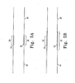
- FIG. 5A shows a schematic cross-sectional representation of the prosthetic modules of FIG. 4B ;
- FIG. 5B shows a schematic cross-sectional representation of interconnected prosthetic modules which have an engagement region shorter than the overlap region
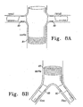
- FIG. 6A shows a partial sectional view of two interconnected prosthetic modules, each with stents attached
- FIG. 6B shows a front perspective view of the external prosthetic module of FIG. 6A ;
- FIG. 7 shows an exploded perspective view of an embodiment of an introducer in perspective view with a partially deployed, bifurcated aortic prosthesis
- FIG. 8A shows a frontal, partial cross-sectional view of prosthetic modules deployed in the aortic and renal arteries
- FIG. 8B shows a frontal, partial cross-sectional view of an embodiment in the aortic and illac arteries
- FIG. 8C shows a frontal, partial cross-sectional view of an embodiment in the iliac and hypogastric arteries
- FIG. 8D shows a frontal, partial cross-sectional view of an embodiment deployed in the abdominal aorta and having a helical prosthetic branch
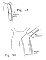
- FIG. 9A shows a frontal, partial cross-sectional view of an embodiment in the thoracic aortic artery
- FIG. 9B shows a frontal, partial cross-sectional view of an embodiment in the thoracic aortic and left subclavian arteries.
- FIG. 9C shows a frontal, partial cross-sectional view of an embodiment having a helical prosthetic branch and deployed into the thoracic aorta.
- the present invention relates to a modular endoluminal prosthesis that is implanted in a vessel or lumen in order to exclude damaged vascular tissue and/or preserve at least some of the existing vascular function.
- the present invention also relates to minimizing, if not eliminating, intermodular pull-out and leaks.
- Telescoping describes the process of establishing the circumferential overlap of two tubular grafts by fitting the end of one tubular graft into the other end
- the two ends are preferably of nearly the same diameter so that circumferential apposition can be promoted through the overlap region.
- the telescoping connections between the prosthetic modules can be significantly and advantageously improved by having specific surface geometries or features on the contact surfaces of those prosthetic modules.
- prosthesis means any replacement for a body part or function of that body part It can also mean a device that enhances or adds functionality to a physiological system,
- endoluminal describes objects that are found or can be placed inside a lumen in the human or animal body.
- a lumen can be an existing lumens or a lumen created by surgical intervention. This includes lumens such as blood vessels, parts of the gastrointestinal tract, ducts such as bile ducts, parts of the respiratory system, etc.
- Endoluminal prosthesis thus describes a prosthesis that can be placed inside one of these lumens.
- graft means the generally cannular or tubular member which acts as an artificial vessel.
- a graft by itself, or with the addition of stents and/or other elements, can be an endoluminal prosthesis.
- prosthesis means any device or structure that adds rigidity, expansion force or support to a graft or prosthesis.
- pull-out force means the maximum force of resistance to partial or full dislocation provided by a modular prosthesis.
- the pull-out force of a prosthesis having two interconnected modules can be measured by an MTS ALLIANCE RT/5 ® tensile testing machine, which is available from the MTS Corporation, Eden Prairie, Minnesota, USA.
- the MTS machine is connected to a computer terminal that is used to control the machine, collect, and process the data.
- a pressurization pump system is attached to the load cell located on the tensile arm of the MTS machine.
- One end of the prosthesis is connected to the pressurization pump, which provides an internal pressure of 60mmHg to simulate the pressure exerted by blood upon the device when deployed in vivo.
- the other end of the prosthesis is sealed.
- the prosthesis is completely immersed in a 37°C water bath during the testing to simulate mean human body temperature.
- the MTS machine pulls the devices at 0.1mm increments until the devices are completely separated.
- the computer will record, inter alia, the highest force with which the modules resist separation, i.e . the pull-out force.
- the embodiment of the present invention shown in Figure 1A is a prosthetic module 10, which includes a substantially tubular graft 12 having a passageway or lumen 13 extending therethrough.
- the tubular graft 12 has an external surface 20, an internal surface 22 and a terminus 24.
- the purpose of the tubular graft 12 is to contain and/or shunt blood or other fluid.
- the size and shape of the prosthetic module 10 can vary significantly depending on the anatomy in which it is to be implanted, and the corresponding module to which this prosthetic module 10 will be connected.
- the tubular graft 12 can have a taper, turns or any other suitable geometry. Physiological variables, deployment characteristics and other factors contribute to the determination of proper size and shape of the prosthetic module 10.
- the tubular graft material is preferably non-porous so that it does not leak or sweat under physiologic forces.
- the graft material is preferably made of woven or knitted polyester (Vascutek Ltd., Renfrewshire, Scotland, UK). Other biocompatible fabrics, non-woven materials and porous sheets may be used as the graft material.
- biocompatible polymers from which porous sheets can be formed include polyesters, such as poly(ethylene terephthalate), polylactide, polyglycolide and copolymers thereof; fluorinated polymers, such as PTFE, expanded PTFE and poly(vinylidene fluoride); polysiloxanes, including polydimethyl siloxane; and polyurethanes, including polyetherurethanes, polyurethane ureas, polyetherurethane ureas, polyurethanes containing carbonate linkages and polyurethanes containing siloxane segments.
- materials that are not inherently biocompatible may be subjected to surface modifications in order to render the materials biocompatible.
- Examples of surface modifications include graft polymerization of biocompatible polymers from the material surface, coating of the surface with a crosslinked biocompatible polymer, chemical modification with biocompatible functional groups, and immobilization of a compatibilizing agent such as heparin or other substances.
- a compatibilizing agent such as heparin or other substances.
- any polymer that may be formed into a porous sheet can be used to make a graft material, provided the final porous material is biocompatible.
- Polymers that can be formed into a porous sheet include polyolefins, polyacrylonitrile, nylons, polyaramids and polysulfones, in addition to polyesters, fluorinated polymers, polysiloxanes and polyurethanes as listed above.
- the porous sheet is made of one or more polymers that do not require treatment or modification to be biocompatible.
- the graft material may include a biocompatible polyurethane.
- biocompatible polyurethanes include THORALON ® (Thoratec, Desion, CA),BIOSPAN ® , BIONATE ® , ELASTHANE TM , PURSIL TM and CARBOSIL TM (Polymer Technology Group, Berkeley, CA).
- THORALON ® is a polyetherurethane urea blended with a siloxane- containing surface modifying additive.
- the polymer is a mixture of base polymer BPS-215 and an additive SMA-300.
- the graft material may also include extracellular matrix materials.
- the "extracellular matrix” is a collagen-rich substance that is found in between cells in animal tissue and serves as a structural element in tissues. It is typically a complex mixture of polysaccharides and proteins secreted by cells.
- the extracellular matrix can be isolated and treated in a variety of ways. Following isolation and treatment, it is referred to as an "extracellular matrix material," or ECMM.
- ECMMs may be isolated from submucosa (including small intestine submucosa), stomach submucosa, urinary bladder submucosa, tissue mucosa, renal capsule, dura mater, liver basement membrane, pericardium or other tissues.
- tela submucosa a preferred type of ECMM
- SIS small intestine submucosa
- Another type of ECMM, isolated from liver basement membrane, is described in U.S. Patent No. 6,379,710 .
- ECMM may also be isolated from pericardium, as described in U. S. Patent No. 4,502, 159 .
- the graft material can be made thicker by making multi-laminate constructs, for example SIS constructs as described in U. S. Patent Nos. 5,968,096 ; 5,955,110 ; 5,885,619 ; and 5,711,969 .
- Projections 18 in the embodiment shown in Figure 1A extend from the terminus 24 to cover a length of the tubular graft 12.
- the projections 18 do not necessarily cover an entire circumference of the tubular graft 12, nor do they have to extend to the terminus 24.
- projection means any element or unit of surface relief, such as a crimp, corrugation, ridge or dimple.
- projection and “surface feature” exclude the roughness that exists solely in the planar weave of a textile, fabric or similar surface.
- projection also includes a single circumvolution (360- degree turn) of a continuous helical or annular projection and any surface relief that projects from the internal surface of the tubular graft 12.
- a “surface feature” is an element or unit of surface geometry (i.e., a projection or groove, or the like) that is capable of engaging a projection when the surface feature contacts the projection.
- Projections and surface features can be closely related. For example, a crimped surface has both surface features and projections. Therefore, for example, reference can be made to projections engaging surface features, or projections engaging projections.
- a "ridge” is a category of projections or surface features that include crimps, corrugations, and other surface geometries.
- the projections 18 on the tubular graft 12 are the result of a specific surface geometry modification.
- the projections 18 are in the shape of a helical crimp or ridge in the fabric of the tubular graft 12.
- the helical crimp like that shown in Figure 1A can be created by mounting the tubular graft 12 over a mandrel of substantially the same diameter.
- a thread, wire or other filament is wrapped helically around the tubular graft 12.
- the helical pitch is preferably between about 0.5mm and about 4mm and more preferably between about 1mm and about 3mm.
- the desired pitch can vary depending on the diameters of the interconnected modules, the characteristics of the tubular graft 12, and the desired pull-out force.
- the assembly as described is then heated to a temperature of 138°C for eight (8) hours. Other temperatures can be used. Typically, the higher the temperature, the shorter the time required for adequate crimping, and vice versa. This may induce helical crimping in the wrapped portion of the prosthesis 10. This process can be varied to suit the constituent polymer used in the prosthesis 10, the thickness of the fabric or fiber, the thread count (if the fabric is woven), the desired rigidity of the crimping, and other factors.
- the tubular graft 12 may also be molded, folded, mechanically crimped or corrugated, or treated in any way known to those of skill in the art to create projections and/or surface features.
- a ridge, including a corrugation, can also be woven into the fabric itself.
- parallel annular or ring-shaped ridges or crimps 14 can be employed. These projections and surface features can be created by wrapping multiple filaments in a circular fashion on a length of the tubular graft 12 and then heat treating the assembly using the method described above.
- the parallel rings can be spaced by any suitable distance, preferably between 0.5mm and 4mm and more preferably between 1 mm and 3mm.
- multiple parallel helices 34 instead of a single helix can be created.
- the process used to create a single helix, as described above in reference to Figure 1 is employed.
- multiple filaments instead of a single filament, are wrapped in parallel helices over a length of the tubular graft 30.
- Any number of helices with any suitable pitch and any suitable angulation relative to the tubular graft 30 can be used.
- the pitch for multiple parallel helices is preferably between about 0.5mm and about 4mm and more preferably between about 1mm and about 3mm.
- the relative angulation is preferably between about 5 and about 10 degrees, and more preferably between about 5 and about 6 degrees.
- the desired pitch and angulation can vary depending on the diameters of the interconnected modules, the characteristics of the tubular graft.30, and the desired pull-out force.
- the tubular graft 36 can also comprise a dimple 38 or dimples.
- a dimple is considered to create a projection on the internal surface 32 and a surface feature on the external surface 25 of the tubular graft 36.
- Such a graft 36 can interconnect with a graft with a similar dimple so that the dimples index or register with each other.
- different types of projections can be used together on a single prosthetic module.
- FIG 4A shows two prosthetic modules 40, 50 that are suitable for interconnection.
- the modules 40, 50 are approximately the same diameter.
- the first or external module 40 has an opening 41 at one end 43 and an internal surface 46.
- the second or internal prosthetic module 50 has an opening 45 at one end 47 and an external surface 48.
- a large difference in diameter can prevent circumferential apposition, thereby preventing adequate intermodular seal.
- the projections and surface feature 42,44 on both modules 40, 50 are substantially matching or complementary. This means that the projections and surface features 42, 44 have substantially the same frequency and amplitude or are otherwise similar. As shown in Figure 4A , the projections 42, 44 on both prosthetic modules 40, 50 are in the form of helical crimps which have approximately the same pitch.
- Complementary projections tend to maximize the surface contact between opposing contact surfaces and ensure that the projections engage or index with opposing projections. Regardless of the type of projection employed, the pull-out force may be increased and the incidence of endoleaks may be decreased if there are substantially complementary projections.
- the telescoping interconnection is formed by inserting one end 47 of the internal prosthetic module 50 into one end 43 of the external prosthetic module 40.
- Figure 4B shows the resulting interconnection of prosthetic modules 40, 50.
- the external prosthetic module 40 overlaps the internal prosthetic module 50, to form an overlap region 26.
- the contact surface of the external prosthetic module 40 is the internal surface 46 and the contact surface of the internal prosthetic module 50 is the external surface 48. Therefore, the external projections 52 on the internal module 50 engage the internal projections 53 of the external module 40 to decrease the risk of modular dislocation and improve the seal so that the interconnection becomes more fluid-tight.
- the contact surfaces 46, 48 preferably have at least partially complementary projections 52, 53. Because the corresponding projections 52, 53 are complementary, they can substantially register or index with each other.
- the overlap region 26 can be of any suitable length. Typically, the longer the overlap region 26, the greater the pull-out force. In a two-piece thoracic endoluminal prosthesis, for example, the overlap region can be about 8cm, although overlap regions may be as short as about 1mm.
- the engagement region 54 is the region in which corresponding, and preferably complementary, projections 52, 53 contact each other.
- the overlap region 26 can be longer than or the same length as the engagement region 54.
- Figure 5A shows an engagement region 54 which is about the same length as the overlap region 26.
- Figure 5B shows interconnected modules in which the engagement region 54 is shorter than the overlap region 26.
- the projections or surface features 42, 44 preferably do not extend beyond the overlap region 26. This minimizes any unnecessary negative hemodynamic effects that may be caused by the projections or surface features 42, 44 that face the lumen. Projections which are adjacent to blood flow may have the effect of thickening the hemodynamic boundary layer, thereby impeding flow, and, in some cases, causing turbulence.
- Figure 5A it is shown schematically how the corresponding, complementary projections 52, 53 engage one another. This encourages maximum surface contact between the complementary projections 52, 53. It is not necessary, however, for the complementary projections 52, 53 to perfectly index with each other.
- Figure 6A shows the use of stents to reinforce the modular interconnection.
- stents 68, 70 at the overlap region 75.
- Internal stents 70 may be attached to the internal module 64, while external stents 68 may be attached to the external module 60. This ensures that the stents 68, 70 reinforce the seal, without interfering with the engagement fit between the opposing projections 72, 74.
- the internal stents 70 are typically held at less than their relaxed diameter by the combined resisting force of the overlapping modules 60, 64 and the external stents 68.
- Internal stents fixed to the internal surface of the internal prosthetic module can also be used without any opposing stents. Stents that are outside of the overlap region 75 will not interfere with the seal, and can therefore be attached to the internal or external surface of the prosthetic modules 60, 64.
- Figure 6B shows an external prosthetic module 60 having projections 72 on the internal contact surface 73 and attached external stents 68.
- Any stent known in the art can be employed, preferably self-expanding zigzag stents.
- the Gianturco Z-stents commercially available from Cook Incorporated, Bloomington, Indiana can be used.
- the stents can be made ofnitinol or stainless steel. They can be self-expanding, balloon-expandable or shape memory stents. These stents can be attached to the external or internal surface of the tubular graft.
- a stent can be attached with a single suture at the peak of each acute bend in the stent or, preferably, multiple sutures at each peak.
- the suture material can be Prolene (5-0) or any other material known to one of skill in the art. Any method of attaching stents known to those of skill in the art can be used.
- Figure 7 shows a self expanding bifurcated prosthesis 120, a self-expanding tubular prosthesis 150 (product code TFB 1 through TFB5, available from Cook Incorporated, Bloomington, Indiana) and an endovascular deployment system 100, also known as an introducer 100, for deploying the prosthesis 120 in a lumen of a patient during a medical procedure.
- product code TFB 1 through TFB5 available from Cook Incorporated, Bloomington, Indiana
- an endovascular deployment system 100 also known as an introducer 100, for deploying the prosthesis 120 in a lumen of a patient during a medical procedure.
- the bifurcated prosthesis 120 has a generally inverted Y-shaped configuration.
- the prosthesis 120 includes a body 123, a shorter leg 160 and a longer leg 132.
- the bifurcated prosthesis 120 comprises a tubular graft material, such as woven polyester, with self-expanding stents attached thereto.
- the self-expanding stents 119 cause the prosthesis 120 to expand following its release from the introducer 100.
- the prosthesis 120 also includes a self-expanding zigzag stent 121 that extends from its proximal end.
- the self-expanding zigzag stent 121 has distally extending barbs 151. When it is released from the introducer 100, the self-expanding zigzag stent 121 anchors the barbs 151, and thus the proximal end of the prosthesis 120, to the lumen of the patient.
- the self-expanding tubular prosthesis 150 is similar to the bifurcated prosthesis 120, but has a unitary (i.e ., non-bifurcated) lumen.
- the tubular prosthesis 150 also comprises a tubular graft material, such as woven polyester, having self-expanding stents attached thereto.
- the tubular prosthesis 150 is configured to form a telescoping interconnection to the shorter leg 160 of the bifurcated prosthesis 120, such that projections on each can engage each other.
- the introducer 100 includes an external manipulation section 180, a distal attachment region 182 and a proximal attachment region 184.
- the distal attachment region 182 and the proximal attachment region 184 secure the distal and proximal ends of the prosthesis 120, respectively.
- the distal and proximal attachment regions 182 and 184 will travel through the lumen to a desired deployment site.
- the external manipulation section 180 which is acted upon by a user to manipulate the introducer, remains outside of the patient throughout the procedure.
- the proximal attachment region 184 of the introducer 100 includes a cylindrical sleeve 110.
- the cylindrical sleeve 110 has a long tapered flexible extension 111 extending from its proximal end.
- the flexible extension 111 has an internal longitudinal apertures (not shown). This longitudinal aperture facilitates advancement of the tapered flexible extension 111 along an insertion wire (not shown).
- the longitudinal aperture also provides a channel for the introduction of medical reagents. For example, it may be desirable to supply a contrast agent to allow angiography to be performed during placement and deployment phases of the medical procedure.
- a thin walled metal tube 115 is fastened to the extension 111.
- the thin walled metal tube 115 is flexible so that the introducer 100 can be advanced along a relatively tortuous vessel, such as a femoral artery, and so that the distal attachment region 182 can be longitudinally and rotationally manipulated.
- the thin walled metal tube 115 extends through the introducer 100 to the manipulation section 180, terminating at a connection means 116.
- connection means 116 is adapted to accept a syringe to facilitate the introduction of reagents into the thin walled metal tube 115.
- the thin walled metal tube 115 is in fluid communication with the apertures 112 of the flexible extension 111. Therefore, reagents introduced into connection means 116 will flow to and emanate from the apertures 112.
- a plastic tube 141 is coaxial with and radially outside of the thin walled metal tube 115.
- the plastic tube 141 is "thick walled" - its wall is preferably several times thicker than that of the thin walled metal tube 115.
- a sheath 130 is coaxial with and radially outside of the plastic tube 141. The thick walled plastic tube 141 and the sheath 130 extend distally to the manipulation region 180.
- the prosthesis 120 is retained in a compressed condition by the sheath 130.
- the sheath 130 extends distally to a gripping and hemostatic sealing means 135 of the external manipulation section 180.
- the sheath 130 is advanced over the cylindrical sleeve 110 of the proximal attachment region 184 while the prosthesis 120 is held in a compressed state by an external force.
- a distal attachment (retention) section 140 is coupled to the thick walled plastic tube 141.
- the distal attachment section 140 retains a distal end 142 of the prosthesis 120 during the procedure.
- the cylindrical sleeve 110 retains the self-expanding zigzag stent 121.
- the distal end 142 of the prosthesis 120 is retained by the distal attachment section 140.
- the distal end 142 of the prosthesis 120 has a loop (not shown) through which a distal trigger wire (not shown) extends.
- the distal trigger wire extends through an aperture (not shown) in the distal attachment section 140 into an annular region between the thin walled tube 115 and the thick walled tube 141.
- the distal trigger wire extends through the annular space to the manipulation region 180.
- the distal trigger wire exits the annular space at a distal wire release mechanism 125.
- the external manipulation section 180 includes a hemostatic sealing means 135.
- the hemostatic sealing means 135 includes a hemostatic seal (not shown) and a side tube 129.
- the hemostatic sealing means 135 also includes a clamping collar (not shown) that clamps the sheath 130 to the hemostatic seal, and a silicone seal ring (not shown) that forms a hemostatic seal around the thick walled plastic tube 141.
- the side tube 129 facilitates the introduction of medical reagents between the thick walled tube 141 and the sheath 130.
- a proximal portion of the external manipulation section 180 includes a release wire actuation section that has a body 136.
- the body 136 is mounted onto the thick walled plastic tube 141.
- the thin walled tube 115 passes through the body 136.
- the distal wire release mechanism 125 and the proximal wire release mechanism 124 are mounted for slidable movement onto the body 136.
- the positioning of the proximal and distal wire release mechanisms 124 and 125 is such that the proximal wire release mechanism 124 must be moved before the distal wire release mechanism 125 can be moved. Therefore, the distal end 142 of the prosthesis 120 cannot be released until the self-expanding zigzag stent 121 has been released, and the barbs 151 have been anchored to the lumen. Clamping screws 137 prevent inadvertent early release of the prosthesis 120.
- a hemostatic seal (not shown) is included so that the release wires can extend out through the body 136 without unnecessary blood loss during the medical procedure.
- a distal portion of the external manipulation section 180 includes a pin vise 139.
- the pin vise 139 is mounted onto the distal end of the body 136.
- the pin vise 139 has a screw cap 146.
- vise jaws (not shown) of the pin vise 139 clamp against or engage the thin walled metal tube 115.
- the thin walled tube 115 can only move with the body 136, and hence the thin walled tube 115 can only move with the thick walled tube 141.
- the screw cap 146 With the screw cap 146 tightened, the entire assembly can be moved together as one piece.
- a second introducer may be used to introduce the tubular prosthesis 150 and create a telescoping interconnection.
- This second introducer may be based on the same principles as the introducer 100 described above, but less complex.
- the second introducer may include a sheath for containing the tubular prosthesis 150 in a compressed state, so that it can be introduced into a targeted anatomy and then released to either self expand or be actively expanded with a balloon.
- the second introducer may also be adapted so that it can introduce the tubular prosthesis 150 by passing it through one ostium in the bifurcated prosthesis 120 and partially out of another ostium until the terminus of the tubular prosthesis 150 that is closest to the external end of the second introducer is properly positioned. At that point, the tubular prosthesis 150 can be released from the second introducer.
- Prosthetic modules are preferably deployed seriatim.
- the modular interconnection between the tubular prosthesis 150 and the bifurcated prosthesis 120 is formed in situ. First the bifurcated prosthesis 120 is deployed, and then the tubular prosthesis 150 is deployed.
- a bifurcated aortic prosthesis 120 as described in WO 98/53761 , can be deployed into the abdominal aorta.
- the bifurcated prosthesis 120 has a generally inverted Y-shaped configuration having a body portion 123, a shorter leg 160 and a longer leg 132.
- the body of the prosthesis is constructed from a woven polyester tube.
- At the proximal end of the prosthesis 120 is a self-expanding stent 121 which extends beyond the end of the prosthesis and has distally extending barbs 151.
- the shorter leg 160 has projections on its distal terminus.
- This bifurcated prosthesis 120 can be deployed in any method known in the art, preferably the method described in WO 98/53761 in which the devise is inserted by an introducer via a surgical cut-down into a femoral artery, and then advanced into the desired position over a stiff wire guide using endoluminal interventional techniques.
- a guide wire (not shown) is first introduced into a femoral artery of the patient and advanced until its tip is beyond the desired deployment region of the prosthesis 120.
- the introducer assembly 100 is fully assembled, and ready for introduction into the patient.
- the prosthesis 120 is retained at one end by the cylindrical sleeve 110 and the other by the distal attachment sections 140, and compressed by the sheath 130. If an aortic aneurism is to be repaired, the introducer assembly 100 can be inserted through a femoral artery over the guide wire, and positioned by radiographic techniques, which are not discussed here.
- the sheath 130 is withdrawn to just proximal of the distal attachment section 140. This action releases the middle portion of the prosthesis 120 so that it can expand radially.
- the proximal self-expanding stent 121 is still retained within the cylindrical sleeve 110. Also, the distal end 142 of the prosthesis 120 is still retained within the external sheath 130.
- the pin vise 139 is released to allow small movements of the thin walled tube 115 with respect to the thick walled tube 141. These movements allow the prosthesis 120 to be lengthened or shortened or rotated or compressed for accurate placement in the desired location within the lumen. X-ray opaque markers (not shown) may be placed along the prosthesis 120 to assist with placement of the prosthesis.
- the proximal trigger wire When the proximal end of the prosthesis 120 is in place, the proximal trigger wire is withdrawn by distal movement of the proximal wire release mechanism 124.
- the proximal wire release mechanism 124 and the proximal trigger wire can be completely removed by passing the proximal wire release mechanism 124 over the pin vise 139, the screw cap 146, and the connection means 116.
- the screw cap 146 of the pin vise 139 is then loosened.
- the thin walled tube 115 can be pushed in a proximal direction to move the cylindrical sleeve 110 in a proximal direction.
- the self-expanding stent 121 expands.
- the barbs 151 grip the walls of the lumen to hold the proximal end of the prosthesis 120 in place. From this stage on, the proximal end of the prosthesis 120 typically cannot be moved.
- the external sheath 130 is withdrawn to distal of the distal attachment section 140. This withdrawal allows the contralateral limb 160 and the longer leg 132 of the prosthesis 120 to expand. At this point, the distal end 142 of the prosthesis 120 may still be moved. Consequently, the prosthesis 120 can still be rotated or lengthened or shortened for accurate positioning. Such positioning of the prosthesis 120 may ensure that the shorter leg 160 extends in the direction of, and/or into a contralateral artery.
- the tubular prosthesis 150 can be deployed.
- the tubular prosthesis 150 is deployed such that it forms a telescoping interconnection with the shorter leg 160 such that it extends from the shorter leg 160 into the contralateral artery.
- the interconnection of the prosthesis 120 and tubular prosthesis 150, especially the formation of the engagement region, is described in greater detail in other portions of this disclosure.
- the method of introduction of the second prosthetic module 150 is as follows.
- a guide wire (not shown) is introduced into the contralateral femoral artery and advanced until its tip is above the region into which the prosthesis is to be deployed.
- the introducer is then advanced over the guide wire with an oscillating and rotating action until preferably about one stent of the extension prosthesis 150 is within the contralateral limb 160.
- a final position check may then be made before the sheath is withdrawn while holding the thick walled tube in place.
- the introducer can then be removed after the gap between the sheath and flexible extension is closed.
- the release of the distal attachment device which contains the ipsilateral leg 132 and the withdrawal of the first introducer 100 can then proceed.
- a leg extension can then be attached to the ipsilateral leg, if indicated.
- a second prosthetic module by passing one end of it through a portion of the first prosthetic module until the other end of the second prosthetic module is properly positioned to form a telescoping connection.
- the second prosthetic module can be allowed to expand, or actively balloon expanded.
- a renal branch extension module can be introduced through an iliac artery, into the iliac leg of the bifurcated prosthesis and through the inside of the prosthesis. Then the renal branch extension can be deployed by passing it through the prosthetic branch until an appropriate length of the renal branch extension is within the prosthetic branch. At this point the renal branch extension can be allowed to expand or actively expanded to form a telescoping connection with the aortic prosthesis.
- FIG. 8A shows a first prosthetic module which is placed into the aorta
- an interconnecting prosthetic module can be placed into the renal ( Figure 8A ), iliac ( Figure 8B ), superior mesenteric, celiac or other artery to form a telescoping interconnection 80.
- Figures 8A also shows a crimped portion of the prosthetic trunk 81 which is interconnectable with the crimped portion of the prosthetic trunk 83 shown on Figure 8B .
- an interconnecting prosthetic module can be placed into the hypogastric artery so that they form a telescoping interconnection 80.
- an interconnecting prosthetic module can be placed into the hypogastric artery, so that they form a telescoping interconnection 80.
- Helical prosthetic branches are further described in U.S. Application Publication No. 2004/0193254 , filed January 13,200 and published September 30, 2004, entitled "Branched Vessel Endoluminal Device.”
- a connecting prosthetic module can be placed into another portion of the thoracic aorta ( Figure 9A ), the left subclavian ( Figure 9B ), left common carotid, innominate or other artery.
- a thoracic aortic module may have a helical branch 87 that extends towards the left subclavian artery to interconnect with a left subclavian extension module at a telescoping interconnection 80.
- prosthetic modules which are implanted in the same artery can be connected to each other ( Figure 8D ).
- the overlap region 80 of each of these embodiments is preferably adapted to the size of the relevant anatomy and the forces to which the prostheses are exposed in the relevant anatomy.
Claims (20)
- Prothèse endoluminale modulaire, comprenant :un premier module prothétique (40) ayant une ouverture à une extrémité (41) et une surface interne (46) ; etun deuxième module prothétique (50) ayant une ouverture à une extrémité (43) et une surface externe (48) ;les premier et deuxième modules (40, 50) étant formés d'un matériau de greffe et pouvant être connectés en insérant la première extrémité (43) du deuxième module (50) dans la première extrémité (41) du premier module (40), la surface interne (46) ou la surface externe (48) comprenant au moins une saillie (42 ou 44) et l'autre surface, la surface interne (46) ou la surface externe (48) comprenant au moins une structure de surface (42, ou 44) formée dans le matériau de greffe, ladite saillie (42 ou 44) et ladite structure de surface (42 ou 44) étant au moins en partie complémentaires de sorte que la structure de surface (42 ou 44) s'engage avec la saillie (42 ou 44) lorsque les modules sont connectés.
- Prothèse selon la revendication 1, dans laquelle l'au moins une saillie (42 ou 44) est une première crête (42 ou 44).
- Prothèse selon la revendication 2, dans laquelle l'au moins une structure de surface (42 ou 44) est une deuxième crête (42 ou 44) et dans laquelle la première crête (42 ou 44) est au moins substantiellement complémentaire de la deuxième crête (42 ou 44).
- Prothèse selon la revendication 3, dans laquelle l'au moins une saillie (42 ou 44) est une première crête hélicoïdale (42 ou 44) et dans laquelle l'au moins une structure de surface (42 ou 44) est une deuxième crête hélicoïdale (42 ou 44).
- Prothèse selon la revendication 4, dans laquelle la première crête hélicoïdale (42 ou 44) et la deuxième crête hélicoïdale (42 ou 44) ont chacune un pas d'au moins 1 mm.
- Prothèse selon la revendication 1, dans laquelle l'au moins une saillie est une première pluralité de crêtes hélicoïdales substantiellement parallèles (34) et l'au moins une structure de surface est une deuxième pluralité de crêtes hélicoïdales substantiellement parallèles, la première pluralité de crêtes hélicoïdales substantiellement parallèles (34) étant au moins substantiellement complémentaire de la deuxième pluralité de crêtes hélicoïdales substantiellement parallèles.
- Prothèse selon la revendication 1, dans laquelle l'au moins une saillie est une première pluralité de crêtes annulaires substantiellement parallèles (14).
- Prothèse selon la revendication 7, dans laquelle l'au moins une structure de surface est une deuxième pluralité de crêtes annulaires substantiellement parallèles (14).
- Prothèse selon la revendication 8, dans laquelle la première pluralité de crêtes annulaires substantiellement parallèles (14) est au moins substantiellement complémentaire de la deuxième pluralité de crêtes annulaires substantiellement parallèles (14).
- Prothèse selon la revendication 8 ou 9, dans laquelle les crêtes annulaires de la première pluralité de crêtes annulaires substantiellement parallèles (14) et de la deuxième pluralité de crêtes annulaires substantiellement parallèles (14) sont espacées de manière à avoir au moins environ 4 crêtes parallèles par centimètre.
- Prothèse selon la revendication 8 ou 9, dans laquelle les crêtes annulaires de la première pluralité de crêtes annulaires substantiellement parallèles (14) et de la deuxième pluralité de crêtes annulaires substantiellement parallèles (14) sont espacées de manière à avoir au moins environ 8 crêtes parallèles par centimètre.
- Prothèse selon la revendication 8 ou 9, dans laquelle les crêtes annulaires de la première pluralité de crêtes annulaires substantiellement parallèles (14) et de la deuxième pluralité de crêtes annulaires substantiellement parallèles (14) ont une hauteur d'au moins environ 0,1 mm.
- Prothèse selon la revendication 1, 2, 6, 8 ou 9, dans laquelle le premier module prothétique est un module prothétique bifurqué (83) comprenant des première et deuxième pattes et dans laquelle la première patte comprend la première extrémité du premier module prothétique et dans laquelle le deuxième module prothétique est un module d'extension dimensionné de manière à former une connexion télescopique avec la première patte.
- Prothèse selon la revendication 1, 2, 6, 7, 8 ou 9, comprenant en outre au moins un premier stent (68 ou 70) disposé soit à l'extérieur sur le premier module prothétique (40) soit à l'intérieur sur le premier module prothétique (40).
- Prothèse selon la revendication 14, comprenant en outre au moins un deuxième stent (68 ou 70) disposé soit à l'intérieur sur le deuxième module prothétique (50) soit à l'extérieur sur le deuxième module prothétique (50).
- Prothèse selon la revendication 1, dans laquelle l'au moins une saillie et l'au moins une structure de surface comprennent des contacts de sertissage.
- Prothèse selon la revendication 1, dans laquelle l'au moins une saillie et l'au moins une structure de surface comprennent des ondulations.
- Prothèse selon la revendication 1, 2, 6, 7, 8, 9, 16 ou 17, dans laquelle l'au moins une saillie est formée dans le matériau de greffe.
- Prothèse selon la revendication 1, 2, 6, 7, 8, 9, 16 ou 17, dans laquelle une connexion de type télescopique entre le premier module prothétique (40) et le deuxième module prothétique (50) est capable de résister à une force d'extraction supérieure à 4 Newtons lorsque la prothèse est pressurisée à 60 mmHg et immergée dans de l'eau à 37°C.
- Prothèse selon la revendication 1, 2, 6, 7, 8, 9, 16 ou 17, dans laquelle la connexion de type télescopique entre le premier module prothétique (40) et le deuxième module prothétique (50) est capable de résister à une force d'extraction supérieure à 7 Newtons lorsque la prothèse est pressurisée à 60 mmHg et immergée dans de l'eau à 37°C.
Applications Claiming Priority (2)
| Application Number | Priority Date | Filing Date | Title |
|---|---|---|---|
| US51061703P | 2003-10-10 | 2003-10-10 | |
| PCT/US2004/033420 WO2005034803A2 (fr) | 2003-10-10 | 2004-10-08 | Prothese endoluminale a modules interconnectables |
Publications (2)
| Publication Number | Publication Date |
|---|---|
| EP1673037A2 EP1673037A2 (fr) | 2006-06-28 |
| EP1673037B1 true EP1673037B1 (fr) | 2009-08-26 |
Family
ID=34435113
Family Applications (1)
| Application Number | Title | Priority Date | Filing Date |
|---|---|---|---|
| EP04794695A Active EP1673037B1 (fr) | 2003-10-10 | 2004-10-08 | Prothese endoluminale a modules interconnectables |
Country Status (8)
| Country | Link |
|---|---|
| US (1) | US20050113905A1 (fr) |
| EP (1) | EP1673037B1 (fr) |
| JP (1) | JP4406649B2 (fr) |
| AT (1) | ATE440564T1 (fr) |
| AU (1) | AU2004279442B8 (fr) |
| CA (1) | CA2540815C (fr) |
| DE (1) | DE602004022842D1 (fr) |
| WO (1) | WO2005034803A2 (fr) |
Cited By (1)
| Publication number | Priority date | Publication date | Assignee | Title |
|---|---|---|---|---|
| US10888414B2 (en) | 2019-03-20 | 2021-01-12 | inQB8 Medical Technologies, LLC | Aortic dissection implant |
Families Citing this family (52)
| Publication number | Priority date | Publication date | Assignee | Title |
|---|---|---|---|---|
| US8034100B2 (en) | 1999-03-11 | 2011-10-11 | Endologix, Inc. | Graft deployment system |
| US6261316B1 (en) | 1999-03-11 | 2001-07-17 | Endologix, Inc. | Single puncture bifurcation graft deployment system |
| US7147661B2 (en) | 2001-12-20 | 2006-12-12 | Boston Scientific Santa Rosa Corp. | Radially expandable stent |
| US9125733B2 (en) | 2003-01-14 | 2015-09-08 | The Cleveland Clinic Foundation | Branched vessel endoluminal device |
| EP3031426B1 (fr) | 2003-10-14 | 2022-07-20 | Cook Medical Technologies LLC | Dispositif d'introduction pour un dispositif de ramification latérale iliaque |
| US7998186B2 (en) * | 2003-10-14 | 2011-08-16 | William A. Cook Australia Pty. Ltd. | Introducer for a side branch device |
| EP1713525B1 (fr) * | 2004-02-09 | 2010-06-16 | Cook Incorporated | Prothese coulee bioremodelable |
| DE102004014337B4 (de) * | 2004-03-22 | 2012-03-15 | Deutsches Zentrum für Luft- und Raumfahrt e.V. | Vorrichtung zum Anschließen einer Einrichtung zur biventrikulären Unterstützung eines Herzes |
| ATE464855T1 (de) * | 2004-03-31 | 2010-05-15 | Cook Inc | Transplantatmaterial und gefässprothese mit extrazellulärer kollagenmatrix und dessen herstellungsverfahren |
| US8048144B2 (en) * | 2004-11-30 | 2011-11-01 | Scimed Life Systems, Inc. | Prosthesis fixation device and method |
| US20060247760A1 (en) * | 2005-04-29 | 2006-11-02 | Medtronic Vascular, Inc. | Methods and apparatus for treatment of aneurysms adjacent branch arteries |
| US8911491B2 (en) * | 2005-09-02 | 2014-12-16 | Medtronic Vascular, Inc. | Methods and apparatus for treatment of aneurysms adjacent branch arteries including branch artery flow lumen alignment |
| US20090054966A1 (en) * | 2006-02-13 | 2009-02-26 | Merlin Md Pte Ltd. | Endovascular device with membrane |
| US7678141B2 (en) * | 2006-04-18 | 2010-03-16 | Medtronic Vascular, Inc. | Stent graft having a flexible, articulable, and axially compressible branch graft |
| US8523931B2 (en) | 2007-01-12 | 2013-09-03 | Endologix, Inc. | Dual concentric guidewire and methods of bifurcated graft deployment |
| US20090088833A1 (en) * | 2007-09-28 | 2009-04-02 | Maximiliano Soetermans | Double wall stent with retrieval member |
| US9414842B2 (en) * | 2007-10-12 | 2016-08-16 | St. Jude Medical, Cardiology Division, Inc. | Multi-component vascular device |
| US9107741B2 (en) | 2007-11-01 | 2015-08-18 | Cook Medical Technologies Llc | Flexible stent graft |
| WO2009086015A2 (fr) * | 2007-12-21 | 2009-07-09 | Boston Scientific Scimed, Inc. | Dispositif d'endoprothèse flexible doté de revêtements polymères à motif |
| US9180030B2 (en) | 2007-12-26 | 2015-11-10 | Cook Medical Technologies Llc | Low profile non-symmetrical stent |
| US8728145B2 (en) | 2008-12-11 | 2014-05-20 | Cook Medical Technologies Llc | Low profile non-symmetrical stents and stent-grafts |
| GB2476451A (en) | 2009-11-19 | 2011-06-29 | Cook William Europ | Stent Graft |
| US8574284B2 (en) * | 2007-12-26 | 2013-11-05 | Cook Medical Technologies Llc | Low profile non-symmetrical bare alignment stents with graft |
| US9226813B2 (en) | 2007-12-26 | 2016-01-05 | Cook Medical Technologies Llc | Low profile non-symmetrical stent |
| US20090171454A1 (en) * | 2007-12-27 | 2009-07-02 | Cook Incorporated | Coated stent and methods of manufacture |
| US8221494B2 (en) | 2008-02-22 | 2012-07-17 | Endologix, Inc. | Apparatus and method of placement of a graft or graft system |
| US8236040B2 (en) | 2008-04-11 | 2012-08-07 | Endologix, Inc. | Bifurcated graft deployment systems and methods |
| EP2293838B1 (fr) | 2008-07-01 | 2012-08-08 | Endologix, Inc. | Système de cathéter |
| US8679572B2 (en) | 2008-08-28 | 2014-03-25 | Cook Medical Technologies, LLC | Coated stent |
| US20100249898A1 (en) * | 2009-03-24 | 2010-09-30 | Medtronic Vascular, Inc. | Stent Graft |
| WO2010127040A1 (fr) | 2009-04-28 | 2010-11-04 | Endologix, Inc. | Appareil et procédé de placement d'une greffe ou d'un système de greffe |
| EP2424447A2 (fr) | 2009-05-01 | 2012-03-07 | Endologix, Inc. | Procédé et dispositif percutanés pour traiter des dissections |
| US10772717B2 (en) | 2009-05-01 | 2020-09-15 | Endologix, Inc. | Percutaneous method and device to treat dissections |
| US8491646B2 (en) | 2009-07-15 | 2013-07-23 | Endologix, Inc. | Stent graft |
| WO2011017123A2 (fr) | 2009-07-27 | 2011-02-10 | Endologix, Inc. | Greffon de stent |
| US9757263B2 (en) | 2009-11-18 | 2017-09-12 | Cook Medical Technologies Llc | Stent graft and introducer assembly |
| JP5323022B2 (ja) * | 2010-10-13 | 2013-10-23 | マーリン エムディー ピーティーイー リミテッド | 膜を有する血管内器具 |
| JP6261339B2 (ja) | 2010-11-02 | 2018-01-17 | エンドロジックス、インク | グラフトまたはグラフトシステムの配置の器具および方法 |
| US9393100B2 (en) | 2010-11-17 | 2016-07-19 | Endologix, Inc. | Devices and methods to treat vascular dissections |
| CN103561807B (zh) | 2011-03-01 | 2015-11-25 | 恩朵罗杰克斯股份有限公司 | 导管系统及其使用方法 |
| US20120290072A1 (en) | 2011-05-12 | 2012-11-15 | Theobald Elizabeth A | Emergency vascular repair prosthesis |
| US8551158B2 (en) | 2011-05-13 | 2013-10-08 | Cook Medical Technologies Llc | Steerable iliac branch device |
| US10335296B2 (en) * | 2011-05-17 | 2019-07-02 | The University Of Kentucky Research Foundation | Graft within a graft endoluminal graft |
| US9066824B2 (en) * | 2011-10-21 | 2015-06-30 | The Charlotte-Mecklenburg Hospital Authority | Method and apparatus for endovascular therapy of aortic pathology |
| US20130166015A1 (en) | 2011-12-22 | 2013-06-27 | Cook Medical Technologies Llc | Hybrid aortic arch replacement |
| US20140358245A1 (en) * | 2013-05-30 | 2014-12-04 | Boston Scientific Scimed, Inc. | Segmental ureteral stent |
| EP3102160B1 (fr) * | 2014-02-07 | 2019-03-20 | Cook Medical Technologies LLC | Stent télescopique |
| US20160143729A1 (en) * | 2014-11-26 | 2016-05-26 | Cormatrix Cardiovascular, Inc. | Regenerative Respiratory Tract Prostheses |
| WO2017004265A1 (fr) | 2015-06-30 | 2017-01-05 | Endologix, Inc. | Ensemble de verrouillage pour accoupler un fil-guide à un système de distribution |
| WO2017015298A1 (fr) * | 2015-07-19 | 2017-01-26 | Sanford Health | Greffe d'endoprothèse vasculaire de pontage ayant des éléments de verrouillage |
| CA3157099C (fr) | 2021-01-19 | 2023-07-11 | Sainath Intellectual Properties, Llc | Endoprotheses telescopiques |
| US11324583B1 (en) | 2021-07-06 | 2022-05-10 | Archo Medical LTDA | Multi-lumen stent-graft and related surgical methods |
Citations (1)
| Publication number | Priority date | Publication date | Assignee | Title |
|---|---|---|---|---|
| WO2005027784A2 (fr) * | 2003-09-19 | 2005-03-31 | Endovascular Technologies, Inc. | Stent modulaire greffable pour reparation endovasculaire d'anevrismes et dissection de la crosse aortique |
Family Cites Families (93)
| Publication number | Priority date | Publication date | Assignee | Title |
|---|---|---|---|---|
| US4604762A (en) * | 1981-02-13 | 1986-08-12 | Thoratec Laboratories Corporation | Arterial graft prosthesis |
| US6221102B1 (en) * | 1983-12-09 | 2001-04-24 | Endovascular Technologies, Inc. | Intraluminal grafting system |
| US4902508A (en) * | 1988-07-11 | 1990-02-20 | Purdue Research Foundation | Tissue graft composition |
| US5628783A (en) * | 1991-04-11 | 1997-05-13 | Endovascular Technologies, Inc. | Bifurcated multicapsule intraluminal grafting system and method |
| US5197976A (en) * | 1991-09-16 | 1993-03-30 | Atrium Medical Corporation | Manually separable multi-lumen vascular graft |
| US5151105A (en) * | 1991-10-07 | 1992-09-29 | Kwan Gett Clifford | Collapsible vessel sleeve implant |
| US5720776A (en) * | 1991-10-25 | 1998-02-24 | Cook Incorporated | Barb and expandable transluminal graft prosthesis for repair of aneurysm |
| BR9405622A (pt) * | 1993-09-30 | 1999-09-08 | Endogad Res Pty Ltd | Enxerto intraluminal |
| DE9319267U1 (de) * | 1993-12-15 | 1994-02-24 | Vorwerk Dierk Dr | Aortenendoprothese |
| US5609627A (en) * | 1994-02-09 | 1997-03-11 | Boston Scientific Technology, Inc. | Method for delivering a bifurcated endoluminal prosthesis |
| US6039749A (en) * | 1994-02-10 | 2000-03-21 | Endovascular Systems, Inc. | Method and apparatus for deploying non-circular stents and graftstent complexes |
| US5653743A (en) * | 1994-09-09 | 1997-08-05 | Martin; Eric C. | Hypogastric artery bifurcation graft and method of implantation |
| US5723003A (en) * | 1994-09-13 | 1998-03-03 | Ultrasonic Sensing And Monitoring Systems | Expandable graft assembly and method of use |
| US5755770A (en) * | 1995-01-31 | 1998-05-26 | Boston Scientific Corporatiion | Endovascular aortic graft |
| US5683449A (en) * | 1995-02-24 | 1997-11-04 | Marcade; Jean Paul | Modular bifurcated intraluminal grafts and methods for delivering and assembling same |
| US5709713A (en) * | 1995-03-31 | 1998-01-20 | Cardiovascular Concepts, Inc. | Radially expansible vascular prosthesis having reversible and other locking structures |
| US5733337A (en) * | 1995-04-07 | 1998-03-31 | Organogenesis, Inc. | Tissue repair fabric |
| US5711969A (en) * | 1995-04-07 | 1998-01-27 | Purdue Research Foundation | Large area submucosal tissue graft constructs |
| US6193745B1 (en) * | 1995-10-03 | 2001-02-27 | Medtronic, Inc. | Modular intraluminal prosteheses construction and methods |
| US6287315B1 (en) * | 1995-10-30 | 2001-09-11 | World Medical Manufacturing Corporation | Apparatus for delivering an endoluminal prosthesis |
| US5591195A (en) * | 1995-10-30 | 1997-01-07 | Taheri; Syde | Apparatus and method for engrafting a blood vessel |
| US6045557A (en) * | 1995-11-10 | 2000-04-04 | Baxter International Inc. | Delivery catheter and method for positioning an intraluminal graft |
| US5824040A (en) * | 1995-12-01 | 1998-10-20 | Medtronic, Inc. | Endoluminal prostheses and therapies for highly variable body lumens |
| US6576009B2 (en) * | 1995-12-01 | 2003-06-10 | Medtronic Ave, Inc. | Bifurcated intraluminal prostheses construction and methods |
| US5865723A (en) * | 1995-12-29 | 1999-02-02 | Ramus Medical Technologies | Method and apparatus for forming vascular prostheses |
| US5755791A (en) * | 1996-04-05 | 1998-05-26 | Purdue Research Foundation | Perforated submucosal tissue graft constructs |
| FR2748199B1 (fr) * | 1996-05-02 | 1998-10-09 | Braun Celsa Sa | Prothese vasculaire transcutanee chirurgicalement anastomosable |
| US5800514A (en) * | 1996-05-24 | 1998-09-01 | Meadox Medicals, Inc. | Shaped woven tubular soft-tissue prostheses and methods of manufacturing |
| US5617878A (en) * | 1996-05-31 | 1997-04-08 | Taheri; Syde A. | Stent and method for treatment of aortic occlusive disease |
| US5755773A (en) * | 1996-06-04 | 1998-05-26 | Medtronic, Inc. | Endoluminal prosthetic bifurcation shunt |
| DK0925077T3 (da) * | 1996-08-23 | 2003-12-08 | Cook Biotech Inc | Fremgangsmåde til opnåelse af en oprenset collagen-baseret matrice fra submucosavæv |
| AU743779B2 (en) * | 1996-12-10 | 2002-02-07 | Cook Biotech, Inc. | Tubular grafts from purified submucosa |
| US6102938A (en) * | 1997-06-17 | 2000-08-15 | Medtronic Inc. | Endoluminal prosthetic bifurcation shunt |
| US6165195A (en) * | 1997-08-13 | 2000-12-26 | Advanced Cardiovascylar Systems, Inc. | Stent and catheter assembly and method for treating bifurcations |
| US6361544B1 (en) * | 1997-08-13 | 2002-03-26 | Advanced Cardiovascular Systems, Inc. | Stent and catheter assembly and method for treating bifurcations |
| US6187033B1 (en) * | 1997-09-04 | 2001-02-13 | Meadox Medicals, Inc. | Aortic arch prosthetic graft |
| US5984955A (en) * | 1997-09-11 | 1999-11-16 | Wisselink; Willem | System and method for endoluminal grafting of bifurcated or branched vessels |
| US6520988B1 (en) * | 1997-09-24 | 2003-02-18 | Medtronic Ave, Inc. | Endolumenal prosthesis and method of use in bifurcation regions of body lumens |
| AUPP083597A0 (en) * | 1997-12-10 | 1998-01-08 | William A Cook Australia Pty Ltd | Endoluminal aortic stents |
| US6395018B1 (en) * | 1998-02-09 | 2002-05-28 | Wilfrido R. Castaneda | Endovascular graft and process for bridging a defect in a main vessel near one of more branch vessels |
| FR2775182B1 (fr) * | 1998-02-25 | 2000-07-28 | Legona Anstalt | Dispositif formant andoprothese intracorporelle endoluminale, en particulier aortique abdominale |
| US6129756A (en) * | 1998-03-16 | 2000-10-10 | Teramed, Inc. | Biluminal endovascular graft system |
| US6887268B2 (en) * | 1998-03-30 | 2005-05-03 | Cordis Corporation | Extension prosthesis for an arterial repair |
| US6290731B1 (en) * | 1998-03-30 | 2001-09-18 | Cordis Corporation | Aortic graft having a precursor gasket for repairing an abdominal aortic aneurysm |
| US6524336B1 (en) * | 1998-04-09 | 2003-02-25 | Cook Incorporated | Endovascular graft |
| US6093203A (en) * | 1998-05-13 | 2000-07-25 | Uflacker; Renan | Stent or graft support structure for treating bifurcated vessels having different diameter portions and methods of use and implantation |
| AU761192B2 (en) * | 1998-06-10 | 2003-05-29 | Converge Medical, Inc. | Sutureless anastomosis systems |
| US6099548A (en) * | 1998-07-28 | 2000-08-08 | Taheri; Syde A. | Apparatus and method for deploying an aortic arch graft |
| US6368345B1 (en) * | 1998-09-30 | 2002-04-09 | Edwards Lifesciences Corporation | Methods and apparatus for intraluminal placement of a bifurcated intraluminal garafat |
| US6273909B1 (en) * | 1998-10-05 | 2001-08-14 | Teramed Inc. | Endovascular graft system |
| US6059824A (en) * | 1998-12-23 | 2000-05-09 | Taheri; Syde A. | Mated main and collateral stent and method for treatment of arterial disease |
| DE60040206D1 (de) * | 1999-02-01 | 2008-10-23 | Univ Texas | Gewebte, zwei und dreiwegige stents und herstellungsverfahren dafür |
| DE19938377A1 (de) * | 1999-08-06 | 2001-03-01 | Biotronik Mess & Therapieg | Stent für Gefässverzweigungen |
| US6344056B1 (en) * | 1999-12-29 | 2002-02-05 | Edwards Lifesciences Corp. | Vascular grafts for bridging a vessel side branch |
| US6325823B1 (en) * | 1999-10-29 | 2001-12-04 | Revasc Corporation | Endovascular prosthesis accommodating torsional and longitudinal displacements and methods of use |
| US6585758B1 (en) * | 1999-11-16 | 2003-07-01 | Scimed Life Systems, Inc. | Multi-section filamentary endoluminal stent |
| US6361555B1 (en) * | 1999-12-15 | 2002-03-26 | Advanced Cardiovascular Systems, Inc. | Stent and stent delivery assembly and method of use |
| US6398807B1 (en) * | 2000-01-31 | 2002-06-04 | Scimed Life Systems, Inc. | Braided branching stent, method for treating a lumen therewith, and process for manufacture therefor |
| US6296661B1 (en) * | 2000-02-01 | 2001-10-02 | Luis A. Davila | Self-expanding stent-graft |
| US7226474B2 (en) * | 2000-05-01 | 2007-06-05 | Endovascular Technologies, Inc. | Modular graft component junctions |
| US6939377B2 (en) * | 2000-08-23 | 2005-09-06 | Thoratec Corporation | Coated vascular grafts and methods of use |
| US6986786B1 (en) * | 2000-09-11 | 2006-01-17 | Scimed Life Systerms, Inc. | Endovascular prostethic devices having hook and loop structures |
| WO2002030329A2 (fr) * | 2000-10-13 | 2002-04-18 | Rex Medical, L.P. | Stents couverts a branche laterale |
| ATE348576T1 (de) * | 2000-11-15 | 2007-01-15 | Mcmurray Fabrics Inc | Röhrenförmige weichgewebsprothese mit gesäumten übergängen |
| US7314483B2 (en) * | 2000-11-16 | 2008-01-01 | Cordis Corp. | Stent graft with branch leg |
| US6942692B2 (en) * | 2000-11-16 | 2005-09-13 | Cordis Corporation | Supra-renal prosthesis and renal artery bypass |
| US7267685B2 (en) * | 2000-11-16 | 2007-09-11 | Cordis Corporation | Bilateral extension prosthesis and method of delivery |
| ES2303851T3 (es) * | 2001-01-19 | 2008-09-01 | Boston Scientific Limited | Introductor para el despliegue de protesis ramificada. |
| US6602225B2 (en) * | 2001-02-28 | 2003-08-05 | Scimed Life Systems, Inc | Substantially circular catheter assembly |
| KR20030094304A (ko) * | 2001-03-28 | 2003-12-11 | 쿡 인코포레이티드 | 모듈식 스텐트 그라프트 조립체 및 그 사용 방법 |
| US7105017B2 (en) * | 2001-04-11 | 2006-09-12 | Andrew Kerr | Axially-connected stent/graft assembly |
| US20030009212A1 (en) * | 2001-07-06 | 2003-01-09 | Andrew Kerr | Axially-connected stent/graft assembly |
| US7175651B2 (en) * | 2001-07-06 | 2007-02-13 | Andrew Kerr | Stent/graft assembly |
| EP1266635A3 (fr) * | 2001-04-11 | 2003-01-29 | Andrew Kerr | Dispositif stent-greffe avec connection axiale |
| CA2352620A1 (fr) * | 2001-07-06 | 2003-01-06 | Pierre-Louis Foucault | Palan a chaine anti-reversion |
| AUPR847201A0 (en) * | 2001-10-26 | 2001-11-15 | Cook Incorporated | Endoluminal graft |
| US6981977B2 (en) * | 2001-10-26 | 2006-01-03 | Atrium Medical Corporation | Body fluid cartridge exchange platform device |
| US7014653B2 (en) * | 2001-12-20 | 2006-03-21 | Cleveland Clinic Foundation | Furcated endovascular prosthesis |
| US7326237B2 (en) * | 2002-01-08 | 2008-02-05 | Cordis Corporation | Supra-renal anchoring prosthesis |
| US20030130720A1 (en) * | 2002-01-08 | 2003-07-10 | Depalma Donald F. | Modular aneurysm repair system |
| US6911040B2 (en) * | 2002-01-24 | 2005-06-28 | Cordis Corporation | Covered segmented stent |
| US7029494B2 (en) * | 2002-02-08 | 2006-04-18 | Scimed Life Systems, Inc. | Braided modular stent with hourglass-shaped interfaces |
| US6939369B2 (en) * | 2002-04-03 | 2005-09-06 | Cook Incorporated | Intraluminal graft assembly and vessel repair system |
| EP1515666B1 (fr) * | 2002-06-26 | 2011-11-16 | Cook Medical Technologies LLC | Fixation greffe/endoprothese |
| US7611529B2 (en) * | 2002-06-28 | 2009-11-03 | Cook Incorporated | Thoracic introducer |
| US20040019375A1 (en) * | 2002-07-26 | 2004-01-29 | Scimed Life Systems, Inc. | Sectional crimped graft |
| US7294147B2 (en) * | 2002-08-23 | 2007-11-13 | Cook Incorporated | Composite prosthesis |
| AU2002951147A0 (en) * | 2002-09-02 | 2002-09-19 | Cook Incorporated | Branch grafting device and method |
| US20040059406A1 (en) * | 2002-09-20 | 2004-03-25 | Cully Edward H. | Medical device amenable to fenestration |
| AU2003295797B2 (en) * | 2002-11-22 | 2009-01-29 | Cook Biotech, Inc. | Stent tissue graft prosthesis |
| US7105020B2 (en) * | 2003-01-14 | 2006-09-12 | The Cleveland Clinic Foundation | Branched vessel endoluminal device |
| JP4970053B2 (ja) * | 2004-01-20 | 2012-07-04 | クック・インコーポレイテッド | 縫合された取付け装置を有する腔内ステントグラフト |
| US7699883B2 (en) * | 2004-10-25 | 2010-04-20 | Myles Douglas | Vascular graft and deployment system |
-
2004
- 2004-10-08 EP EP04794695A patent/EP1673037B1/fr active Active
- 2004-10-08 AU AU2004279442A patent/AU2004279442B8/en active Active
- 2004-10-08 US US10/962,001 patent/US20050113905A1/en not_active Abandoned
- 2004-10-08 WO PCT/US2004/033420 patent/WO2005034803A2/fr active Search and Examination
- 2004-10-08 AT AT04794695T patent/ATE440564T1/de not_active IP Right Cessation
- 2004-10-08 DE DE602004022842T patent/DE602004022842D1/de active Active
- 2004-10-08 CA CA2540815A patent/CA2540815C/fr active Active
- 2004-10-08 JP JP2006534435A patent/JP4406649B2/ja active Active
Patent Citations (1)
| Publication number | Priority date | Publication date | Assignee | Title |
|---|---|---|---|---|
| WO2005027784A2 (fr) * | 2003-09-19 | 2005-03-31 | Endovascular Technologies, Inc. | Stent modulaire greffable pour reparation endovasculaire d'anevrismes et dissection de la crosse aortique |
Cited By (1)
| Publication number | Priority date | Publication date | Assignee | Title |
|---|---|---|---|---|
| US10888414B2 (en) | 2019-03-20 | 2021-01-12 | inQB8 Medical Technologies, LLC | Aortic dissection implant |
Also Published As
| Publication number | Publication date |
|---|---|
| DE602004022842D1 (de) | 2009-10-08 |
| WO2005034803A2 (fr) | 2005-04-21 |
| US20050113905A1 (en) | 2005-05-26 |
| JP4406649B2 (ja) | 2010-02-03 |
| WO2005034803A3 (fr) | 2005-05-19 |
| EP1673037A2 (fr) | 2006-06-28 |
| JP2007508064A (ja) | 2007-04-05 |
| AU2004279442B2 (en) | 2010-04-01 |
| CA2540815A1 (fr) | 2005-04-21 |
| ATE440564T1 (de) | 2009-09-15 |
| AU2004279442A8 (en) | 2011-11-24 |
| CA2540815C (fr) | 2011-10-04 |
| AU2004279442B8 (en) | 2011-11-24 |
| AU2004279442A1 (en) | 2005-04-21 |
Similar Documents
| Publication | Publication Date | Title |
|---|---|---|
| EP1673037B1 (fr) | Prothese endoluminale a modules interconnectables | |
| US9095461B2 (en) | Aorta and branch vessel stent grafts and method | |
| EP1737389B1 (fr) | Dispositif de reparation d'une endoprothese | |
| AU2007284361B2 (en) | Stent graft extension | |
| US9198787B2 (en) | Conformable prosthesis delivery system and method for deployment thereof | |
| AU2007258592B2 (en) | Stent with a crush-resistant zone | |
| EP2331013B1 (fr) | Dispositif endoluminal pour vaisseaux ramifiés | |
| US8043363B2 (en) | Endoluminal prosthesis | |
| CA3009244C (fr) | Protheses vasculaires utilisees pour le traitement des anevrismes | |
| EP1696828B1 (fr) | Prolongations reliees les unes aux autres pour prothese endoluminale | |
| EP1965732B1 (fr) | Dispositif endoluminal comprenant un mecanisme de fixation proximale ou distale et procedes d'utilisation de ce dernier | |
| EP1998715B1 (fr) | Greffon de stent pour extension de branche iliaque | |
| WO2006113501A1 (fr) | Prothese endoluminale | |
| AU2018214103B1 (en) | A stent-graft |
Legal Events
| Date | Code | Title | Description |
|---|---|---|---|
| PUAI | Public reference made under article 153(3) epc to a published international application that has entered the european phase |
Free format text: ORIGINAL CODE: 0009012 |
|
| 17P | Request for examination filed |
Effective date: 20060403 |
|
| AK | Designated contracting states |
Kind code of ref document: A2 Designated state(s): AT BE BG CH CY CZ DE DK EE ES FI FR GB GR HU IE IT LI LU MC NL PL PT RO SE SI SK TR |
|
| DAX | Request for extension of the european patent (deleted) | ||
| 17Q | First examination report despatched |
Effective date: 20070814 |
|
| GRAP | Despatch of communication of intention to grant a patent |
Free format text: ORIGINAL CODE: EPIDOSNIGR1 |
|
| GRAS | Grant fee paid |
Free format text: ORIGINAL CODE: EPIDOSNIGR3 |
|
| GRAA | (expected) grant |
Free format text: ORIGINAL CODE: 0009210 |
|
| AK | Designated contracting states |
Kind code of ref document: B1 Designated state(s): AT BE BG CH CY CZ DE DK EE ES FI FR GB GR HU IE IT LI LU MC NL PL PT RO SE SI SK TR |
|
| REG | Reference to a national code |
Ref country code: GB Ref legal event code: FG4D |
|
| REG | Reference to a national code |
Ref country code: CH Ref legal event code: EP |
|
| REG | Reference to a national code |
Ref country code: IE Ref legal event code: FG4D |
|
| REF | Corresponds to: |
Ref document number: 602004022842 Country of ref document: DE Date of ref document: 20091008 Kind code of ref document: P |
|
| PG25 | Lapsed in a contracting state [announced via postgrant information from national office to epo] |
Ref country code: SE Free format text: LAPSE BECAUSE OF FAILURE TO SUBMIT A TRANSLATION OF THE DESCRIPTION OR TO PAY THE FEE WITHIN THE PRESCRIBED TIME-LIMIT Effective date: 20090826 Ref country code: FI Free format text: LAPSE BECAUSE OF FAILURE TO SUBMIT A TRANSLATION OF THE DESCRIPTION OR TO PAY THE FEE WITHIN THE PRESCRIBED TIME-LIMIT Effective date: 20090826 Ref country code: AT Free format text: LAPSE BECAUSE OF FAILURE TO SUBMIT A TRANSLATION OF THE DESCRIPTION OR TO PAY THE FEE WITHIN THE PRESCRIBED TIME-LIMIT Effective date: 20090826 |
|
| PG25 | Lapsed in a contracting state [announced via postgrant information from national office to epo] |
Ref country code: PL Free format text: LAPSE BECAUSE OF FAILURE TO SUBMIT A TRANSLATION OF THE DESCRIPTION OR TO PAY THE FEE WITHIN THE PRESCRIBED TIME-LIMIT Effective date: 20090826 Ref country code: SI Free format text: LAPSE BECAUSE OF FAILURE TO SUBMIT A TRANSLATION OF THE DESCRIPTION OR TO PAY THE FEE WITHIN THE PRESCRIBED TIME-LIMIT Effective date: 20090826 |
|
| PG25 | Lapsed in a contracting state [announced via postgrant information from national office to epo] |
Ref country code: BG Free format text: LAPSE BECAUSE OF FAILURE TO SUBMIT A TRANSLATION OF THE DESCRIPTION OR TO PAY THE FEE WITHIN THE PRESCRIBED TIME-LIMIT Effective date: 20091126 Ref country code: PT Free format text: LAPSE BECAUSE OF FAILURE TO SUBMIT A TRANSLATION OF THE DESCRIPTION OR TO PAY THE FEE WITHIN THE PRESCRIBED TIME-LIMIT Effective date: 20091228 Ref country code: CY Free format text: LAPSE BECAUSE OF FAILURE TO SUBMIT A TRANSLATION OF THE DESCRIPTION OR TO PAY THE FEE WITHIN THE PRESCRIBED TIME-LIMIT Effective date: 20090826 |
|
| PG25 | Lapsed in a contracting state [announced via postgrant information from national office to epo] |
Ref country code: ES Free format text: LAPSE BECAUSE OF FAILURE TO SUBMIT A TRANSLATION OF THE DESCRIPTION OR TO PAY THE FEE WITHIN THE PRESCRIBED TIME-LIMIT Effective date: 20091207 Ref country code: EE Free format text: LAPSE BECAUSE OF FAILURE TO SUBMIT A TRANSLATION OF THE DESCRIPTION OR TO PAY THE FEE WITHIN THE PRESCRIBED TIME-LIMIT Effective date: 20090826 Ref country code: DK Free format text: LAPSE BECAUSE OF FAILURE TO SUBMIT A TRANSLATION OF THE DESCRIPTION OR TO PAY THE FEE WITHIN THE PRESCRIBED TIME-LIMIT Effective date: 20090826 Ref country code: CZ Free format text: LAPSE BECAUSE OF FAILURE TO SUBMIT A TRANSLATION OF THE DESCRIPTION OR TO PAY THE FEE WITHIN THE PRESCRIBED TIME-LIMIT Effective date: 20090826 Ref country code: RO Free format text: LAPSE BECAUSE OF FAILURE TO SUBMIT A TRANSLATION OF THE DESCRIPTION OR TO PAY THE FEE WITHIN THE PRESCRIBED TIME-LIMIT Effective date: 20090826 |
|
| REG | Reference to a national code |
Ref country code: NL Ref legal event code: V1 Effective date: 20100501 |
|
| PG25 | Lapsed in a contracting state [announced via postgrant information from national office to epo] |
Ref country code: SK Free format text: LAPSE BECAUSE OF FAILURE TO SUBMIT A TRANSLATION OF THE DESCRIPTION OR TO PAY THE FEE WITHIN THE PRESCRIBED TIME-LIMIT Effective date: 20090826 Ref country code: MC Free format text: LAPSE BECAUSE OF NON-PAYMENT OF DUE FEES Effective date: 20091031 |
|
| REG | Reference to a national code |
Ref country code: CH Ref legal event code: PL |
|
| PG25 | Lapsed in a contracting state [announced via postgrant information from national office to epo] |
Ref country code: BE Free format text: LAPSE BECAUSE OF FAILURE TO SUBMIT A TRANSLATION OF THE DESCRIPTION OR TO PAY THE FEE WITHIN THE PRESCRIBED TIME-LIMIT Effective date: 20090826 |
|
| PLBE | No opposition filed within time limit |
Free format text: ORIGINAL CODE: 0009261 |
|
| STAA | Information on the status of an ep patent application or granted ep patent |
Free format text: STATUS: NO OPPOSITION FILED WITHIN TIME LIMIT |
|
| REG | Reference to a national code |
Ref country code: FR Ref legal event code: ST Effective date: 20100630 |
|
| PG25 | Lapsed in a contracting state [announced via postgrant information from national office to epo] |
Ref country code: NL Free format text: LAPSE BECAUSE OF NON-PAYMENT OF DUE FEES Effective date: 20100501 Ref country code: FR Free format text: LAPSE BECAUSE OF NON-PAYMENT OF DUE FEES Effective date: 20091102 |
|
| 26N | No opposition filed |
Effective date: 20100527 |
|
| PG25 | Lapsed in a contracting state [announced via postgrant information from national office to epo] |
Ref country code: GR Free format text: LAPSE BECAUSE OF FAILURE TO SUBMIT A TRANSLATION OF THE DESCRIPTION OR TO PAY THE FEE WITHIN THE PRESCRIBED TIME-LIMIT Effective date: 20091127 Ref country code: LI Free format text: LAPSE BECAUSE OF NON-PAYMENT OF DUE FEES Effective date: 20091031 Ref country code: CH Free format text: LAPSE BECAUSE OF NON-PAYMENT OF DUE FEES Effective date: 20091031 |
|
| PG25 | Lapsed in a contracting state [announced via postgrant information from national office to epo] |
Ref country code: IT Free format text: LAPSE BECAUSE OF NON-PAYMENT OF DUE FEES Effective date: 20091008 |
|
| PG25 | Lapsed in a contracting state [announced via postgrant information from national office to epo] |
Ref country code: LU Free format text: LAPSE BECAUSE OF NON-PAYMENT OF DUE FEES Effective date: 20091008 |
|
| PG25 | Lapsed in a contracting state [announced via postgrant information from national office to epo] |
Ref country code: HU Free format text: LAPSE BECAUSE OF FAILURE TO SUBMIT A TRANSLATION OF THE DESCRIPTION OR TO PAY THE FEE WITHIN THE PRESCRIBED TIME-LIMIT Effective date: 20100227 |
|
| PG25 | Lapsed in a contracting state [announced via postgrant information from national office to epo] |
Ref country code: TR Free format text: LAPSE BECAUSE OF FAILURE TO SUBMIT A TRANSLATION OF THE DESCRIPTION OR TO PAY THE FEE WITHIN THE PRESCRIBED TIME-LIMIT Effective date: 20090826 |
|
| PGFP | Annual fee paid to national office [announced via postgrant information from national office to epo] |
Ref country code: IE Payment date: 20230925 Year of fee payment: 20 Ref country code: GB Payment date: 20230914 Year of fee payment: 20 |
|
| PGFP | Annual fee paid to national office [announced via postgrant information from national office to epo] |
Ref country code: DE Payment date: 20230915 Year of fee payment: 20 |