EP1672913A2 - Image pickup apparatus - Google Patents
Image pickup apparatus Download PDFInfo
- Publication number
- EP1672913A2 EP1672913A2 EP05026841A EP05026841A EP1672913A2 EP 1672913 A2 EP1672913 A2 EP 1672913A2 EP 05026841 A EP05026841 A EP 05026841A EP 05026841 A EP05026841 A EP 05026841A EP 1672913 A2 EP1672913 A2 EP 1672913A2
- Authority
- EP
- European Patent Office
- Prior art keywords
- image pickup
- lens
- image
- control means
- frequency
- Prior art date
- Legal status (The legal status is an assumption and is not a legal conclusion. Google has not performed a legal analysis and makes no representation as to the accuracy of the status listed.)
- Granted
Links
- 238000001514 detection method Methods 0.000 claims abstract description 46
- 230000006835 compression Effects 0.000 claims description 7
- 238000007906 compression Methods 0.000 claims description 7
- 238000000605 extraction Methods 0.000 description 16
- 238000010586 diagram Methods 0.000 description 14
- 238000011156 evaluation Methods 0.000 description 12
- 230000008859 change Effects 0.000 description 11
- 230000004438 eyesight Effects 0.000 description 7
- 230000006870 function Effects 0.000 description 7
- 238000000034 method Methods 0.000 description 5
- 238000006243 chemical reaction Methods 0.000 description 4
- 230000003287 optical effect Effects 0.000 description 4
- 230000008569 process Effects 0.000 description 4
- 230000001105 regulatory effect Effects 0.000 description 3
- 230000004044 response Effects 0.000 description 3
- 230000008901 benefit Effects 0.000 description 2
- 239000000284 extract Substances 0.000 description 2
- 230000004304 visual acuity Effects 0.000 description 2
- 230000004075 alteration Effects 0.000 description 1
- 238000009937 brining Methods 0.000 description 1
- 230000003111 delayed effect Effects 0.000 description 1
- 230000007274 generation of a signal involved in cell-cell signaling Effects 0.000 description 1
- 230000006872 improvement Effects 0.000 description 1
- 230000010354 integration Effects 0.000 description 1
- 238000002360 preparation method Methods 0.000 description 1
- 230000007704 transition Effects 0.000 description 1
Images








Classifications
-
- H—ELECTRICITY
- H04—ELECTRIC COMMUNICATION TECHNIQUE
- H04N—PICTORIAL COMMUNICATION, e.g. TELEVISION
- H04N23/00—Cameras or camera modules comprising electronic image sensors; Control thereof
- H04N23/60—Control of cameras or camera modules
- H04N23/66—Remote control of cameras or camera parts, e.g. by remote control devices
- H04N23/663—Remote control of cameras or camera parts, e.g. by remote control devices for controlling interchangeable camera parts based on electronic image sensor signals
-
- H—ELECTRICITY
- H04—ELECTRIC COMMUNICATION TECHNIQUE
- H04N—PICTORIAL COMMUNICATION, e.g. TELEVISION
- H04N23/00—Cameras or camera modules comprising electronic image sensors; Control thereof
- H04N23/60—Control of cameras or camera modules
- H04N23/67—Focus control based on electronic image sensor signals
- H04N23/673—Focus control based on electronic image sensor signals based on contrast or high frequency components of image signals, e.g. hill climbing method
Definitions
- the present invention relates to an image pickup apparatus to which an exchangeable lens system is set and capable of picking up a still image and a moving image.
- a maximum power point tracking system is conventionally known as an automatic focus regulation system used for an image input unit such as a video camera.
- a solid-state image pickup device such as a CCD image pickup device
- This automatic focus regulation system does not require a special optical member for focus regulation and has an advantage of accurately brining into focus independently of a distance even for a distant place or near place.
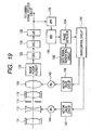
- a maxim-power-point-tracking-type automatic focus regulation system is briefly described below by referring to FIG. 19.
- variable power lens The light from an object enters the image pickup face (photoelectric conversion face) of an image pickup device 120 by passing through a fixed first lens group 110, second lens group 112 for variable power (hereafter referred to as variable power lens), aperture stop 114, fixed third lens group 116 and fourth lens group 118 (hereafter referred to as focusing lens) having a focus regulation function and a function for correcting movement of a focus face in accordance with variable power.
- the image pickup device 120 converts an optical image on the image pickup face into an electrical signal.
- An output signal for the image pickup device 120 is sample-held by a CDS circuit 122, amplified to a predetermined level by an AGC circuit 124 and converted into a digital signal by an A/D converter 126.
- An output signal of the A/D converter 126 is supplied to a not-illustrated camera signal process circuit.
- An output of the A/D converter 126 is also applied to a band-pass filter (BPF) 128.
- BPF band-pass filter
- the BPF 128 extracts a predetermined high-frequency component from the image data output from the A/D converter 126.
- Every output of the BPF 128 is converted into a straight-polarity signal by an ABS circuit 130.
- a gate signal generation circuit 132 generates a gate signal for designating a portion corresponding to the inside of a focus detection area in an image pickup screen.
- a phase detector 134 phase-detects (for example, peak-holds or integrates) only a signal corresponding to the inside of the focus detection area from an output of the ABS circuit 130 in accordance with the gate signal.
- the phase-detected signal is output at an interval synchronizing with integral multiples of a vertical sync signal as an AF (automatic focus regulation) evaluation value.
- a main control circuit 136 constituted of a microcomputer captures an output (AF evaluation value) of the phase detector 134.
- Focusing speed corresponding to a focusing degree and a motor driving direction according to an increment of AF evaluation value are decided based on the captured signal and a motor driving circuit 138 is controlled based on the decided result.
- the motor driving circuit 138 drives a focus motor 140 in accordance with an instruction from the main control circuit 136 to move the focusing lens 118 to a designated position at a designated speed.
- the focusing lens 118 is controlled at a position where an output of the BPF 128 is maximized.
- the main control circuit 136 also rotates a zoom motor 144 by a motor driving circuit 142 to move the variable power lens 112 up to a designated position in accordance with a variable power operation by a user.
- FIG. 20 shows a flowchart of the maximum-power-point-tracking-type automatic focus regulation system by the main control circuit 136.
- the main control circuit 136 continuously captures outputs (AF evaluation values) of the phase detector 134 at intervals synchronizing with integral multiples of a vertical sync signal to execute automatic focus regulation control.
- AF return control is started (S1) and the focusing lens 118 is driven in a direction in which an AF evaluation value increases to perform the maximum power point tracking control (S2).
- the apex of the mountain is determined (S3) and stopped at a highest-level point to wait for restart (S4).
- the AF return control is restarted (S5).
- Japanese Patent Application Laid-Open No. H08-327893 discloses a moving focus regulator for excluding the influence of a spatial frequency of an object whose focus will be detected and always performing focus regulation in accordance with a best image face position without changing focus detection optical system.
- an image pickup apparatus capable of picking up a moving image and a still image and selecting the number of recording pixels in still image pickup and a high-vision (HD) image pickup apparatus also in moving images are spread.
- HD high-vision
- an early exchangeable lens system corresponds to image recording of only a standard TV signal
- a camera and lens capable of picking up a resolution still image higher than a TV signal and high vision are developed and put on sale and new and old camera lenses are present.
- the lens only has a resolution for standard TV and an AF system may be present in the lens.
- the AF system only has a system for conventional standard TV.
- the frequency to be extracted is usually previously decided by a camera.
- a signal to be extracted has a high frequency
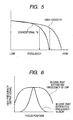
- a signal change is small when the peak is greatly deviated compared with a case where a frequency to be extracted is low (when focus position is horizontally deviated from the peak position of a high-frequency output signal) as shown in FIG. 6 and response is delayed.
- a case may occur in which the peak of the fluctuation of the aberration of a lens is detected because the focusing operation is performed by a signal equal to or higher than the resolution of a lens and AF is stopped at a position of not focusing an object.
- AF is a lens for high vision and signal for focusing is generated by the camera and transmitted to the lens.
- the lens receives only a signal for standard TV, when performing AF for high vision, a case may occur in which AF starts from a greatly deviated state or operation nearby focusing is not properly performed.
- a lens has an AF function regulated to NTSC, the focusing signal of the camera is regulated to an NTSC-type frequency to be extracted and a still image is recorded at higher pixel and higher density than in the case of NTSC type.
- FIG. 7 is an illustration showing comparison between spatial frequency characteristic to be resolved of NTSC and spatial frequency to be resolved when recording images at high pixel and high density when picking up a still image.
- the spatial frequency to be resolved in the case of NTSC is as NTSCHz and a still image is picked up at 3 million pixels more than a necessary spatial frequency of NTSC.
- the spatial frequency to be resolved "Stil-300" Hz becomes higher than the spatial frequency to be resolved for NTSC.
- the spatial frequency to be resolved is not a frequency at a limit in which the frequency can be resolved but a frequency having high enough MTF is an object spatial frequency to be resolved as indicated by the arrows in FIG. 7.
- a necessary spatial frequency characteristic depends on the setting.
- the performance of a lens depends on the focal length, focus position and aperture stop and they are also factors of change in resolving powers of the lens.
- a spatial frequency to be resolved differs between WIDE (wide side) and TELE (telephoto side) for the focal length as shown in FIG. 9.
- a spatial frequency to be resolved in WIDE is higher than in TELE because an object image becomes more minute in WIDE than in TELE.
- a spatial frequency to be resolved depends on F No. of an aperture stop. Therefore, a phenomenon same as the case previously described occurs in AF.
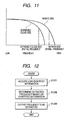
- FIG. 11 is an example in which spatial frequencies to be resolved at focus positions differ.
- an object of the present invention to provide an image pickup apparatus capable of realizing a preferable automatic focus regulation performance in any exchangeable lens, its lens state, combination with a camera or image pickup state.
- an image pickup apparatus of the present invention whose lens is exchangeable is constituted so as to change an output of focus detection means from the information sent from the exchangeable lens to a camera or information sent from the camera to the lens or change a frequency detected by the focus detection means.
- FIG. 1 shows a schematic block diagram of an embodiment of the present invention.
- a lens unit 200 which is an exchangeable lens is set to a camera unit 201 through a lens mount 201a and camera mount 202a.
- the light from an object enters the image pickup surface (photoelectric conversion surface) of an image pickup device 20 by passing through a fixed first lens group 10, variable power lens 12, aperture stop 14, fixed third lens group 16 and focusing lens 18.
- the image pickup device 20 converts an optical image on an image pickup face into electrical signals.
- An output signal of the image pickup device 20 is sample-held by a CDS circuit 22, amplified to a predetermined level by an AGC circuit 24 and then converted into a digital signal by an A/D converter 26.
- An output signal of the A/D converter 26 is supplied to a not-illustrated camera signal process circuit.
- An output of the A/D converter 26 is input to an AF preprocess circuit 28.
- the AF preprocess circuit 28 generates an AF evaluation value and supplies the AF evaluation value to a camera main control circuit 31 constituted of a microcomputer.
- the camera main control circuit 31 captures an output (AF evaluation value) of the AF preprocess circuit 28 and transmits the output to a lens main control circuit 30 through the camera mount 202a and lens mount 201a.
- the lens main control circuit 30 decides a focusing speed and motor driving direction in which an AF evaluation value increases in accordance with a focusing degree and controls a motor driving circuit 32 in accordance with the decided speed and direction.
- the motor driving circuit 32 drives a focus motor 34 in accordance with an instruction from the camera main control circuit 31 and thereby moves the focusing lens 18 to a focusing position at the decided speed.
- the focusing lens 18 is controlled to a position at which an AF evaluation value is maximized.
- the lens main control circuit 31 rotates a zoom motor 38 by a motor driving circuit 36 in accordance with the variable power operation by a user to move the variable power lens 12 up to a designated position.
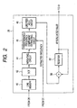
- FIG. 2 shows a schematic block diagram of an example of the AF preprocess circuit 28.
- FIG. 3 is an illustration of a focus detection area in a screen and a pixel configuration in the focus detection area.
- a focus detection area 56 is set in a screen 54 of one frame or one field.
- the focus detection area 56 is constituted of a plurality of horizontal lines 58 and each horizontal line 58 is constituted of a plurality of pixels 60.
- the line memory 40 stores pixel data for one horizontal line P0, P1, and Pn of the focus detection area 56 from the output data of the A/D converter 26.
- a discrete cosine conversion (DCT) circuit 42 orthogonally converts the image data for one horizontal line in the line memory 40 and outputs frequency area data F0, F1, ... and Fn.
- DCT discrete cosine conversion
- a weighting circuit 44 multiples an output of the DCT circuit 42 by predetermined constants K0 to Kn so that frequency components have almost uniform level.
- the weighting circuit 44 outputs k0 x P0, K1 x P1, ... and Kn x Pn.
- the predetermined frequency component extraction circuit 46 extracts only components instructed by the camera main control circuit 31 from outputs k0 x P0, K1 x P1, ... and Kn x Pn of the weighting circuit 44 and outputs the components.
- a line peak hold circuit 48 holds the maximum value in outputs for one line output from the predetermined frequency component extraction circuit 46 and updates a held value by the maximum value of the next horizontal line every horizontal line.
- An adder 50 and a register 52 constitute an accumulator.
- the accumulator functions as a vertical-directional integration circuit and accumulates and adds outputs of the line peak hold circuit 48.
- the register 52 is set to zero. Then, the adder 5.0 adds an output of the register 52 to an output of the line peak hold circuit 48 and writes an addition result in the register 52.
- the stored value of the register 52 is supplied to the camera main control circuit 31 as an AF evaluation value.
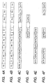
- FIGS. 4A to 4F show examples of data transition in the line memory 40, DCT circuit 42, weighting circuit 46 and predetermined frequency component extraction circuit 46.
- FIG. 4A shows a data string stored in the line memory 40
- FIG. 4B shows a data string output from the DCT circuit 42
- FIG. 4C shows an output data string of the weighting circuit 42.
- FIGS. 4D, 4E and 4F are output examples of the predetermined frequency component extraction circuit 46.
- F0 is a lowest frequency component nearby a DC component, frequency becomes higher in order of F1, F2, ... and Fn is a highest frequency component.
- the camera main control circuit 30 obtains the identification signal of a lens from communication with the lens main control circuit 31. It is possible to determine the characteristic of the lens in accordance with the identification signal. For example, it is possible to determine a content format of a signal necessary for the lens-side performance (SD or HD) AF.
- SD or HD lens-side performance
- a camera can change the contents by the identification signal- when transmitting a signal for AF to the lens.
- FIG. 12 shows a flow
- the camera main control circuit 30 obtains the identification information on a lens.
- the band of a frequency extracted from an image signal is determined from the lens identification information and decided in S1203.
- the camera main control circuit 31 determines whether to send the information on a frequency extracted to the lens main control circuit to the lens in accordance with a lens identification signal and can transmit the information according to necessity.
- This function makes it possible to perform preferable AF even if frequencies extracted from image signals differ when performing AF are different.
- This embodiment has a feature of deciding a spatial frequency to be resolved and deciding the frequency band of a high frequency component extracted from an image signal by adding a lens state and image pickup state.
- FIG. 13 A portion same as FIG. 1 is provided with the same symbol and its description is omitted.
- Image pickup state detection means 87 detects a still image and moving image and image pickup states such as the size, number of pixels, compression rate, pixel density of an image to be picked up.
- the detected image pickup states are input to the camera main control circuit 30.
- states of a lens such as focal length information, aperture stop information and focus information are detected by lens state detection means 88 and input to the lens main control circuit 31.
- a spatial frequency which can be resolved depends on a lens state, image pickup mode or compression rate.
- a spatial frequency to be resolved is 10 MHz
- a lens state is a spatial frequency to be resolved of 0.5 MHz when a lens state is telephoto side end infinite F8
- 0.5 MHz is sufficient for a frequency extracted by an image signal for AF.
- the main control circuits 30 and 31 respectively have a spatial frequency detection function and extraction frequency determination function.
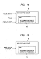
- Extraction frequency determination data is stored in ROMs 30a and 31a in the main control circuits 30 and 31 shown in FIGS. 14 and 15.
- frequency band frequency component data is extracted by the predetermined frequency component extraction circuit 46 in accordance with the extraction frequency determination data stored in built-in ROMs 30a and 31a from an image pickup state and lens state.
- the camera reads image pickup states (image pickup mode and image compression rate, etc) and in S1602, transmits a spatial frequency to be resolved or frequency to be extracted from an image signal to the lens.
- the lens reads the lens state.and compares a spatial frequency to be resolved obtained in S1604 with a frequency extracted from an image signal obtained from the spatial frequency.
- a lower frequency of them is designated to the camera as a frequency to be extracted in S1605 and the camera obtains a signal in accordance with the designation in S1604.
- the lens main control circuit 31 reads the lens state in S1701 and obtains frequency information extracted from a spatial frequency to be resolved in the lens state or frequency information extracted from the image signal in S1702.
- the frequency is transmitted to the camera main control circuit 30 in S1703 and the camera main control circuit 30 reads an image pickup state in S1704.
- a spatial frequency to be resolved or frequency extracted from the image signal is detected from the pickup state in S1705 and compared with the information from the lens state obtained in S1703.
- automatic focusing means is present in the camera, it is allowed to communicate AF driving information such as speed, direction and driving value to the lens to perform AF.
- the lens main control circuit 31 reads a lens state.
- the spatial frequency or frequency information is transmitted to the camera main control circuit 30 in S1803 and the camera main control circuit 30 reads an image pickup state in S1804.
- a spatial frequency to be resolved or frequency extracted from an image signal is detected from the pickup state in S1805 and compared with the information from the lens state obtained in S1803.
- a lower frequency of them is a frequency to be extracted in S1806 to perform AF in accordance with the decided extraction frequency.
- a spatial frequency to be resolved is 5 MHz from the lens information and a spatial frequency to be resolved is 3 MHz from the image pickup state, a frequency to be resolved is decided as 3 MHz because 3 MHz is lower than 5 MHz.
- a frequency band to be extracted to the predetermined frequency component extraction circuit 46 is designated as 3 MHz.
- the spatial frequency to be resolved in the above case is not a limit frequency to be resolved but it is a sufficient frequency of MTF and approx. 80% of a resolution limit frequency.
Landscapes
- Engineering & Computer Science (AREA)
- Multimedia (AREA)
- Signal Processing (AREA)
- Studio Devices (AREA)
- Automatic Focus Adjustment (AREA)
- Focusing (AREA)
Abstract
Description
- The present invention relates to an image pickup apparatus to which an exchangeable lens system is set and capable of picking up a still image and a moving image.
- A maximum power point tracking system is conventionally known as an automatic focus regulation system used for an image input unit such as a video camera.
- This is a system for extracting a high frequency component in an image signal obtained from a solid-state image pickup device such as a CCD image pickup device, driving an image pickup lens so that the high frequency component is maximized and regulating a focal point.
- This automatic focus regulation system does not require a special optical member for focus regulation and has an advantage of accurately brining into focus independently of a distance even for a distant place or near place.
- A maxim-power-point-tracking-type automatic focus regulation system is briefly described below by referring to FIG. 19.
- The light from an object enters the image pickup face (photoelectric conversion face) of an
image pickup device 120 by passing through a fixedfirst lens group 110,second lens group 112 for variable power (hereafter referred to as variable power lens),aperture stop 114, fixedthird lens group 116 and fourth lens group 118 (hereafter referred to as focusing lens) having a focus regulation function and a function for correcting movement of a focus face in accordance with variable power. - The
image pickup device 120 converts an optical image on the image pickup face into an electrical signal. - An output signal for the
image pickup device 120 is sample-held by aCDS circuit 122, amplified to a predetermined level by anAGC circuit 124 and converted into a digital signal by an A/D converter 126. - An output signal of the A/
D converter 126 is supplied to a not-illustrated camera signal process circuit. - Because the process content of the camera signal process circuit is publicly known but it is not related with the present invention, further description thereof is omitted.
- An output of the A/
D converter 126 is also applied to a band-pass filter (BPF) 128. - The
BPF 128 extracts a predetermined high-frequency component from the image data output from the A/D converter 126. - Every output of the
BPF 128 is converted into a straight-polarity signal by anABS circuit 130. - A gate
signal generation circuit 132 generates a gate signal for designating a portion corresponding to the inside of a focus detection area in an image pickup screen. - A
phase detector 134 phase-detects (for example, peak-holds or integrates) only a signal corresponding to the inside of the focus detection area from an output of theABS circuit 130 in accordance with the gate signal. - The phase-detected signal is output at an interval synchronizing with integral multiples of a vertical sync signal as an AF (automatic focus regulation) evaluation value.
- A
main control circuit 136 constituted of a microcomputer captures an output (AF evaluation value) of thephase detector 134. - Focusing speed corresponding to a focusing degree and a motor driving direction according to an increment of AF evaluation value are decided based on the captured signal and a
motor driving circuit 138 is controlled based on the decided result. - The
motor driving circuit 138 drives afocus motor 140 in accordance with an instruction from themain control circuit 136 to move the focusinglens 118 to a designated position at a designated speed. - Thereby, the focusing
lens 118 is controlled at a position where an output of theBPF 128 is maximized. - The
main control circuit 136 also rotates azoom motor 144 by amotor driving circuit 142 to move thevariable power lens 112 up to a designated position in accordance with a variable power operation by a user. - Thereby, it is possible to change focal lengths and image pickup magnifications are changed.
- FIG. 20 shows a flowchart of the maximum-power-point-tracking-type automatic focus regulation system by the
main control circuit 136. - The
main control circuit 136 continuously captures outputs (AF evaluation values) of thephase detector 134 at intervals synchronizing with integral multiples of a vertical sync signal to execute automatic focus regulation control. - When power supply is turned on or an image pickup preparation mode is started, AF return control is started (S1) and the focusing
lens 118 is driven in a direction in which an AF evaluation value increases to perform the maximum power point tracking control (S2). - By overshooting and the returning the apex of a mountain (maximum point of power), the apex of the mountain is determined (S3) and stopped at a highest-level point to wait for restart (S4). When detecting that the level of the AF evaluation value lowers from the level at the time of stop, the AF return control is restarted (S5).
- Moreover, in addition to a system for extracting a high-frequency component in an image signal by the
BPF 128, a configuration of extracting a high-frequency component from a conversion result of a two-dimensional orthogonal converter used for image compression and using the component for automatic focus regulation is also proposed in recent years. - Furthermore, Japanese Patent Application Laid-Open No. H08-327893 discloses a moving focus regulator for excluding the influence of a spatial frequency of an object whose focus will be detected and always performing focus regulation in accordance with a best image face position without changing focus detection optical system.
- The conventional maximum-power-point-tracking-type automatic focus regulation system is described above. In recent years, however, change in lenses to zoom and high magnification and change in image pickup means to high pixel and high density are accelerated for image pickup of a camera.
- Moreover, an image pickup apparatus capable of picking up a moving image and a still image and selecting the number of recording pixels in still image pickup and a high-vision (HD) image pickup apparatus also in moving images are spread.
- In the case of an exchangeable lens system, a camera and lens advance in improvement of the resolution of an image pickup apparatus and image quality with the times and evolve to various conformations.
- For example, though an early exchangeable lens system corresponds to image recording of only a standard TV signal, a camera and lens capable of picking up a resolution still image higher than a TV signal and high vision are developed and put on sale and new and old camera lenses are present.
- It is preferable that combination of them is performed without problem in image pickup in combination of marketability, merchandize property and compatibility.
- For example, when a camera corresponds to HD and image pickup cannot be performed by even combination with an old lens designed for standard TV, the marketability and merchandize property as an exchangeable lens system are extremely deteriorated.
- However, in the case of this combination, because a camera is high-resolution vision, a spatial frequency to be resolved as shown in FIG. 5 is high.
- Therefore, a high extraction frequency characteristic of high frequency component to be detected from an image signal is also necessary compared to a conventional TV system.
- In some cases, there may be a case in which proper AF cannot be performed unless there is further information. However, in the case of this example, the lens only has a resolution for standard TV and an AF system may be present in the lens.
- However, the AF system only has a system for conventional standard TV.
- In the case of focus detection means, it is necessary to extract the high-frequency component in the image signal as described above. However, the frequency to be extracted is usually previously decided by a camera.
- For example, when a focus signal of a camera is set for high vision in accordance with the above' combination, a case in which characteristic is not satisfied and the operation of AF may not be proper.
- Moreover, when an AF system is present in a lens, it is possible to perform only AF for conventional TV.
- Therefore, it is considered that the AF does not properly operate or does not operate at all.
- That is, because a signal to be extracted has a high frequency, a signal change is small when the peak is greatly deviated compared with a case where a frequency to be extracted is low (when focus position is horizontally deviated from the peak position of a high-frequency output signal) as shown in FIG. 6 and response is delayed.
- Moreover, a case may occur in which the peak of the fluctuation of the aberration of a lens is detected because the focusing operation is performed by a signal equal to or higher than the resolution of a lens and AF is stopped at a position of not focusing an object.
- However, a case may occur in which a lens for high vision is used, a camera for standard TV is used, AF is a lens for high vision and signal for focusing is generated by the camera and transmitted to the lens.
- In this case, because the lens receives only a signal for standard TV, when performing AF for high vision, a case may occur in which AF starts from a greatly deviated state or operation nearby focusing is not properly performed.
- Moreover, a case is assumed in which a camera capable of picking up a still image and NTSC-type moving image is used, a lens has an AF function regulated to NTSC, the focusing signal of the camera is regulated to an NTSC-type frequency to be extracted and a still image is recorded at higher pixel and higher density than in the case of NTSC type.
- FIG. 7 is an illustration showing comparison between spatial frequency characteristic to be resolved of NTSC and spatial frequency to be resolved when recording images at high pixel and high density when picking up a still image.
- As shown in FIG. 7, it is assumed that the spatial frequency to be resolved in the case of NTSC is as NTSCHz and a still image is picked up at 3 million pixels more than a necessary spatial frequency of NTSC.
- In this case, the spatial frequency to be resolved "Stil-300" Hz becomes higher than the spatial frequency to be resolved for NTSC.
- In this case, it is assumed that the spatial frequency to be resolved is not a frequency at a limit in which the frequency can be resolved but a frequency having high enough MTF is an object spatial frequency to be resolved as indicated by the arrows in FIG. 7.
- Though this deciding method is optional, sufficient MTF is obtained when setting approx. 80% of a limit resolution spatial frequency as a target.
- Therefore, when picking up a still image of 3 million pixels by using the spatial frequency of "NTSC" Hz to be resolved of NTSC as a frequency characteristic for focusing detecting of AF, defocusing can be recognized due to the difference of resolution limit of the spatial frequency.
- That is, it is impossible to detect the peak of a focus for the object of "Still-300" Hz.
- Also in this case, a problem same as a case of combination of standard TV and HD previously described occurs.
- That is, it is difficult to detect a focus position from a defocusing state and as a result, response characteristic is deteriorated. Similarly, because positional width of peak is narrow nearby the peak, a problem in lacking in stability occurs by overshooting a peak position.
- However, by taking only still image pickup as an example, in the case of a camera having a plurality of settings of a picked-up image such as compression rate and number of pixels for recording, a necessary spatial frequency characteristic depends on the setting.
- For example, when it is possible to select one million pixels and two million pixels as the number of image-picking up pixels, the necessary AF frequency characteristic for them differs as shown in FIG. 8.
- Therefore, a problem of AF operation same as the case in which a camera corresponds to high vision and standard TV occurs as previously described.
- Moreover, the performance of a lens depends on the focal length, focus position and aperture stop and they are also factors of change in resolving powers of the lens.
- Therefore, frequency characteristics necessary for AF are also changed due to a lens state. For example, a spatial frequency to be resolved differs between WIDE (wide side) and TELE (telephoto side) for the focal length as shown in FIG. 9.
- In general, a spatial frequency to be resolved in WIDE is higher than in TELE because an object image becomes more minute in WIDE than in TELE.
- Nowadays, while change in zoom to high magnification advances, the difference between spatial frequencies to be resolved at WIDE end and TELE end tends to increase.
- Moreover, as shown in FIG. 10, a spatial frequency to be resolved depends on F No. of an aperture stop. Therefore, a phenomenon same as the case previously described occurs in AF.
- Furthermore, the resolving power of a lens may be changed depending on a focus position. FIG. 11 is an example in which spatial frequencies to be resolved at focus positions differ.
- Therefore, a problem same as the case previously described occurs in AF.
- Various problems of AF occur in a lens and an image pickup apparatus because a frequency to be resolved differs in accordance with the type or state of a lens to be set like this and the type or image pickup state of a camera, respectively.
- Therefore, it is an object of the present invention to provide an image pickup apparatus capable of realizing a preferable automatic focus regulation performance in any exchangeable lens, its lens state, combination with a camera or image pickup state.
- To achieve the above object, in the case of an image pickup apparatus of the present invention whose lens is exchangeable is constituted so as to change an output of focus detection means from the information sent from the exchangeable lens to a camera or information sent from the camera to the lens or change a frequency detected by the focus detection means.
- The above and other objects, features, and advantages of the invention will become more apparent from the following detailed description taken in conjunction with the accompany drawings.
-
- FIG. 1 is a schematic block diagram of
embodiment 1 of the present invention; - FIG. 2 is a schematic block diagram of an example of an AF preprocess circuit;
- FIG. 3 is an illustration of a focus detection area in a screen and an image configuration in the focus detection area;
- FIGS. 4A, 4B, 4C, 4D, 4E and 4F are data characteristic diagrams of a
line memory 40,DCT circuit 42,weighting circuit 46 and predetermined-frequency-component extraction circuit 46; - FIG. 5 is an extraction frequency characteristic diagram of a high frequency component detected from an image signal;
- FIG. 6 is a relational diagram between output of signal of high frequency component of AF and position of focus when an extraction frequency is high;
- FIG. 7 is a comparison diagram between spatial frequency characteristic to be resolved of NTSC and spatial frequency to be resolved when recording a still image at a high pixel and high density;
- FIG. 8 is a frequency characteristic diagram of a spatial frequency to be resolved of AF;
- FIG. 9 is a spatial frequency characteristic diagram to be resolved of wide and tele;
- FIG. 10 is a spatial frequency characteristic diagram to be resolved in accordance with FNo. of an aperture stop;
- FIG. 11 is a spatial frequency characteristic diagram to be resolved at the position of a focus;
- FIG. 12 is an operation flow chart of
embodiment 1 of the present invention; - FIG. 13 is a schematic block diagram of
embodiment 2 of the present invention; - FIG. 14 is an illustration of a main control circuit constituting the
embodiment 2 of the present invention; - FIG. 15 is an illustration of a main control circuit constituting the
embodiment 2 of the present invention; - FIG. 16 is an operational flowchart of the
embodiment 2 of the present invention; - FIG. 17 is an operational flowchart of the
embodiment 2 of the present invention; - FIG. 18 is an operational flowchart of the
embodiment 2 of the present invention; - FIG. 19 is a block diagram of a conventional maximum-power-point-tracking-type automatic focus regulator; and
- FIG. 20 is a flowchart of automatic focus regulation operation by a conventional maximum-power-point-tracking-type main control circuit.
- The present invention is described below in accordance with embodiments by referring to the accompanying drawings.
- Embodiments of the present invention are described below in detail by referring to the accompanying drawings.
- FIG. 1 shows a schematic block diagram of an embodiment of the present invention.
- A
lens unit 200 which is an exchangeable lens is set to acamera unit 201 through alens mount 201a andcamera mount 202a. - The light from an object enters the image pickup surface (photoelectric conversion surface) of an
image pickup device 20 by passing through a fixedfirst lens group 10,variable power lens 12, aperture stop 14, fixedthird lens group 16 and focusinglens 18. - The
image pickup device 20 converts an optical image on an image pickup face into electrical signals. - An output signal of the
image pickup device 20 is sample-held by aCDS circuit 22, amplified to a predetermined level by anAGC circuit 24 and then converted into a digital signal by an A/D converter 26. - An output signal of the A/
D converter 26 is supplied to a not-illustrated camera signal process circuit. - An output of the A/
D converter 26 is input to anAF preprocess circuit 28. - The
AF preprocess circuit 28 generates an AF evaluation value and supplies the AF evaluation value to a cameramain control circuit 31 constituted of a microcomputer. - The camera
main control circuit 31 captures an output (AF evaluation value) of theAF preprocess circuit 28 and transmits the output to a lensmain control circuit 30 through thecamera mount 202a andlens mount 201a. - The lens
main control circuit 30 decides a focusing speed and motor driving direction in which an AF evaluation value increases in accordance with a focusing degree and controls amotor driving circuit 32 in accordance with the decided speed and direction. - The
motor driving circuit 32 drives afocus motor 34 in accordance with an instruction from the cameramain control circuit 31 and thereby moves the focusinglens 18 to a focusing position at the decided speed. - Thereby, the focusing
lens 18 is controlled to a position at which an AF evaluation value is maximized. - The lens
main control circuit 31 rotates azoom motor 38 by amotor driving circuit 36 in accordance with the variable power operation by a user to move thevariable power lens 12 up to a designated position. - Thereby, it is possible to change focal lengths and image pickup magnifications are changed.
- FIG. 2 shows a schematic block diagram of an example of the
AF preprocess circuit 28. - FIG. 3 is an illustration of a focus detection area in a screen and a pixel configuration in the focus detection area.
- A
focus detection area 56 is set in ascreen 54 of one frame or one field. Thefocus detection area 56 is constituted of a plurality ofhorizontal lines 58 and eachhorizontal line 58 is constituted of a plurality ofpixels 60. - As shown in FIG. 2, the
line memory 40 stores pixel data for one horizontal line P0, P1, and Pn of thefocus detection area 56 from the output data of the A/D converter 26. - A discrete cosine conversion (DCT)
circuit 42 orthogonally converts the image data for one horizontal line in theline memory 40 and outputs frequency area data F0, F1, ... and Fn. - A
weighting circuit 44 multiples an output of theDCT circuit 42 by predetermined constants K0 to Kn so that frequency components have almost uniform level. - That is, the
weighting circuit 44 outputs k0 x P0, K1 x P1, ... and Kn x Pn. - The predetermined frequency
component extraction circuit 46 extracts only components instructed by the cameramain control circuit 31 from outputs k0 x P0, K1 x P1, ... and Kn x Pn of theweighting circuit 44 and outputs the components. - A line
peak hold circuit 48 holds the maximum value in outputs for one line output from the predetermined frequencycomponent extraction circuit 46 and updates a held value by the maximum value of the next horizontal line every horizontal line. - An
adder 50 and aregister 52 constitute an accumulator. - The accumulator functions as a vertical-directional integration circuit and accumulates and adds outputs of the line
peak hold circuit 48. - That is, at first, the
register 52 is set to zero. Then, the adder 5.0 adds an output of theregister 52 to an output of the linepeak hold circuit 48 and writes an addition result in theregister 52. - By executing the above operation for all
horizontal lines 58 in thefocus detection area 56, an accumulated value of maximum values of predetermined frequency components of allhorizontal lines 58 in the focus detection area is stored in theregister 52. - The stored value of the
register 52 is supplied to the cameramain control circuit 31 as an AF evaluation value. - FIGS. 4A to 4F show examples of data transition in the
line memory 40,DCT circuit 42,weighting circuit 46 and predetermined frequencycomponent extraction circuit 46. - FIG. 4A shows a data string stored in the
line memory 40, FIG. 4B shows a data string output from theDCT circuit 42 and FIG. 4C shows an output data string of theweighting circuit 42. - FIGS. 4D, 4E and 4F are output examples of the predetermined frequency
component extraction circuit 46. - In the case of outputs F0 to Fn of the
DCT circuit 42, F0 is a lowest frequency component nearby a DC component, frequency becomes higher in order of F1, F2, ... and Fn is a highest frequency component. - The camera
main control circuit 30 obtains the identification signal of a lens from communication with the lensmain control circuit 31. It is possible to determine the characteristic of the lens in accordance with the identification signal. For example, it is possible to determine a content format of a signal necessary for the lens-side performance (SD or HD) AF. - In the case of the present invention, a camera can change the contents by the identification signal- when transmitting a signal for AF to the lens.
- In the case of this embodiment, it is described that a frequency characteristic extracted from an image signal is changed and transmitted to a lens.
- For example, when there are a plurality of exchangeable lenses having AF systems different from each other and an AF signal suitable for each lens is previously known, it is possible to output a signal converted into a format suitable for each lens in accordance with lens identification information. Moreover, it is allowed to directly send a signal for driving the
focus motor 34 from the cameramain control circuit 31. Thereby, it is possible to perform preferable AF by any combination. - FIG. 12 shows a flow.
- In S1201, the camera
main control circuit 30 obtains the identification information on a lens. - In S1202, the band of a frequency extracted from an image signal is determined from the lens identification information and decided in S1203.
- In this case, the camera
main control circuit 31 determines whether to send the information on a frequency extracted to the lens main control circuit to the lens in accordance with a lens identification signal and can transmit the information according to necessity. - This function makes it possible to perform preferable AF even if frequencies extracted from image signals differ when performing AF are different.
- Then,
embodiment 2 of the present invention is described below. - This embodiment has a feature of deciding a spatial frequency to be resolved and deciding the frequency band of a high frequency component extracted from an image signal by adding a lens state and image pickup state.
- Description is continued by referring to FIG. 13. A portion same as FIG. 1 is provided with the same symbol and its description is omitted.
- Image pickup state detection means 87 detects a still image and moving image and image pickup states such as the size, number of pixels, compression rate, pixel density of an image to be picked up. The detected image pickup states are input to the camera
main control circuit 30. - Moreover, states of a lens such as focal length information, aperture stop information and focus information are detected by lens state detection means 88 and input to the lens
main control circuit 31. - Even for the same lens and image pickup means, a spatial frequency which can be resolved depends on a lens state, image pickup mode or compression rate.
- For example, even if an image pickup state is 2 million pixels of a still image and free from compression and a spatial frequency to be resolved is 10 MHz, when a lens state is a spatial frequency to be resolved of 0.5 MHz when a lens state is telephoto side end infinite F8, 0.5 MHz is sufficient for a frequency extracted by an image signal for AF.
- As previously described, because the spatial frequency is high, when raising a frequency to be extracted, a problem occurs that it is difficult to find a focus direction at the time of defocusing because change of signals is small at a portion other than a portion nearby focus peak.
- Therefore, it is necessary to decide an optimum extraction frequency for AF by adding a lens characteristic and image pickup state.
- The
main control circuits - Extraction frequency determination data is stored in
ROMs main control circuits - It is decided in which frequency band frequency component data is extracted by the predetermined frequency
component extraction circuit 46 in accordance with the extraction frequency determination data stored in built-inROMs - For example, a case in which a camera decides an extraction frequency in accordance with a designation from a lens is described below by referring to the flow in FIG. 16.
- In S1601, the camera reads image pickup states (image pickup mode and image compression rate, etc) and in S1602, transmits a spatial frequency to be resolved or frequency to be extracted from an image signal to the lens.
- In S1603, the lens reads the lens state.and compares a spatial frequency to be resolved obtained in S1604 with a frequency extracted from an image signal obtained from the spatial frequency.
- A lower frequency of them is designated to the camera as a frequency to be extracted in S1605 and the camera obtains a signal in accordance with the designation in S1604.
- Moreover, a case in which the camera obtains lens information from the lens is described in accordance with the flow in FIG. 17.
- The lens
main control circuit 31 reads the lens state in S1701 and obtains frequency information extracted from a spatial frequency to be resolved in the lens state or frequency information extracted from the image signal in S1702. - The frequency is transmitted to the camera
main control circuit 30 in S1703 and the cameramain control circuit 30 reads an image pickup state in S1704. - A spatial frequency to be resolved or frequency extracted from the image signal is detected from the pickup state in S1705 and compared with the information from the lens state obtained in S1703.
- It is also allowed to obtain a lower frequency of them as a frequency to be extracted in S1706.
- Moreover, because automatic focusing means is present in the camera, it is allowed to communicate AF driving information such as speed, direction and driving value to the lens to perform AF.
- Description is made below by referring to the flow in FIG. 18. In S1801, the lens
main control circuit 31 reads a lens state. - In S1802, a spatial frequency to be resolved in the lens state or frequency information extracted from an image signal is obtained.
- The spatial frequency or frequency information is transmitted to the camera
main control circuit 30 in S1803 and the cameramain control circuit 30 reads an image pickup state in S1804. - A spatial frequency to be resolved or frequency extracted from an image signal is detected from the pickup state in S1805 and compared with the information from the lens state obtained in S1803.
- A lower frequency of them is a frequency to be extracted in S1806 to perform AF in accordance with the decided extraction frequency.
- It is allowed to set a frequency band to be selected to the spatial frequency of the lens but when the band exceeds the upper limit or lower limit, the band is set to the upper limit value or lower limit value.
- For example, when lens information is WIDE end, F8 and infinite end and an image, pickup state is a moving image and NTSC, a spatial frequency to be resolved is 5 MHz from the lens information and a spatial frequency to be resolved is 3 MHz from the image pickup state, a frequency to be resolved is decided as 3 MHz because 3 MHz is lower than 5 MHz.
- Therefore, in this case, a frequency band to be extracted to the predetermined frequency
component extraction circuit 46 is designated as 3 MHz. - The spatial frequency to be resolved in the above case is not a limit frequency to be resolved but it is a sufficient frequency of MTF and approx. 80% of a resolution limit frequency.
- By this, because a frequency to be extracted is selected according to a spatial frequency which can be actually resolved according to the lens information and the pickup information, defocusing does not occur.
- As described above, according to the present invention, it is possible to solve the problems that the response of AF from a defocused state and operations are not stabilized.
- As many apparently widely different embodiments of the present invention can be made without departing from the sprit and scope thereof, it is to be understood that the invention is not limited to the specific embodiment thereof except as defined in the appended claims.
Claims (10)
- An image pickup apparatus comprising:an interchangeable image-pickup lens unit having a focus lens unit, information on the image pickup lens, and a first control means for controlling movement of the focus lens unit ; anda camera unit having:an image pickup unit for picking up the image of an object,a signal processing unit for extracting a signal in a predetermined frequency band from an image obtained by the image pickup means,second control means for computing a signal indicating a focusing degree in accordance with a signal input from the signal processing unit, whereinthe second control means determines the frequency to be extracted in accordance with the information on the lens.
- The image pickup apparatus according to claim 1, wherein
the camera unit further includes image pickup state detection means and the second control means further decides a predetermined frequency to be extracted in accordance with a detection result of the detection means. - The image pickup apparatus according to claim 1 or 2, wherein
the image pickup lens unit has lens state detection means for detecting a state of a lens, a detection result of the lens state detection means is transmitted to the second control means and the second control means further determines the frequency to be extracted in accordance with the transmitted detection result of the lens state detection means. - The image pickup apparatus according to claim 3, wherein
the detection result of the image pickup state detection means is transmitted to the first control means, the first control circuit determines a predetermined frequency in accordance with the transmitted detection result of the image pickup state detection means and the detection result of the lens state detection means and transmits the predetermined frequency to the second control means and the second control means further determines the predetermined frequency to be extracted in accordance with the transmitted predetermined frequericy. - The image pickup apparatus according to claim 1, wherein the information on the image pickup lens is an identification number for identifying lens unit characteristics.
- The image pickup apparatus according to claim 2 wherein the image pickup state detection means is at least one of a moving image and still image pickup state, standard image pickup and high-vision image pickup state and the number of pixels of an image pickup device and size, compression rate and pixel density of an image to be picked up.
- The image pickup apparatus according to claim 3 wherein the image pickup state detection means includes at least one of zoom information, aperture stop information and focus position information.
- An image pickup apparatus comprising:an interchangeable image-pickup lens unit having a focus lens unit, lens state detection means, and a first control means for controlling movement of the focus lens unit; anda camera unit having an image pickup unit for picking up the image of an object, a signal processing unit for extracting a signal in a predetermined frequency band from an image obtained by the image pickup means and a second control means for computing a signal indicating a focusing degree in accordance with a signal input from the signal processing unit, whereinthe second control means determines the frequency to be extracted in accordance with the detection result of the lens state detection means transmitted from the lens unit.
- An image pickup apparatus comprising:an interchangeable image pickup lens unit having a focus lens unit, lens state detection means, and a first control means for controlling movement of the focus lens unit; anda camera unit having an image pickup unit for picking up the image of an object, signal processing unit for extracting a signal in a predetermined frequency band from an image obtained by the image pickup means and a second control means for computing a signal indicating a focusing degree in accordance with a signal input from the signal processing unit, wherein the first control means determines the frequency to be extracted in accordance with a detection result of the lens state detection means and transmits the frequency to the second control means.
- The image pickup apparatus according to claim 9 wherein the camera unit has an image pickup state detection means, transmits a detection result of the image pickup state detection means to the first control means, the first control means determines a predetermined frequency in accordance with the transmitted detection result of the image pickup state detection means and transmits the predetermined frequency to the second control means.
Applications Claiming Priority (1)
| Application Number | Priority Date | Filing Date | Title |
|---|---|---|---|
| JP2004366035A JP4522249B2 (en) | 2004-12-17 | 2004-12-17 | Imaging device |
Publications (3)
| Publication Number | Publication Date |
|---|---|
| EP1672913A2 true EP1672913A2 (en) | 2006-06-21 |
| EP1672913A3 EP1672913A3 (en) | 2009-01-07 |
| EP1672913B1 EP1672913B1 (en) | 2013-11-20 |
Family
ID=36129767
Family Applications (1)
| Application Number | Title | Priority Date | Filing Date |
|---|---|---|---|
| EP05026841.6A Expired - Lifetime EP1672913B1 (en) | 2004-12-17 | 2005-12-08 | Image pickup apparatus |
Country Status (3)
| Country | Link |
|---|---|
| US (1) | US7692711B2 (en) |
| EP (1) | EP1672913B1 (en) |
| JP (1) | JP4522249B2 (en) |
Families Citing this family (7)
| Publication number | Priority date | Publication date | Assignee | Title |
|---|---|---|---|---|
| JP5173131B2 (en) * | 2005-10-26 | 2013-03-27 | キヤノン株式会社 | Optical apparatus and focus adjustment method |
| KR100856275B1 (en) | 2006-12-05 | 2008-09-03 | 삼성전기주식회사 | Module having part identification ID and electronic device for setting characteristic variable value of part using same |
| JP5550304B2 (en) * | 2009-10-19 | 2014-07-16 | キヤノン株式会社 | Imaging device |
| KR101579737B1 (en) * | 2010-01-05 | 2015-12-23 | 삼성전자주식회사 | Auto focus adjusting apparatus and camera system |
| US8611737B2 (en) * | 2010-12-22 | 2013-12-17 | Canon Kabushiki Kaisha | Lens driving device, control method, and lens system |
| WO2013161262A1 (en) * | 2012-04-26 | 2013-10-31 | パナソニック株式会社 | Display control system, indicating device, and display panel |
| JP6313685B2 (en) * | 2014-05-01 | 2018-04-18 | キヤノン株式会社 | Imaging apparatus and control method thereof |
Citations (2)
| Publication number | Priority date | Publication date | Assignee | Title |
|---|---|---|---|---|
| US20040119871A1 (en) | 2002-12-13 | 2004-06-24 | Kosuke Nobuoka | Autofocus apparatus |
| US20040130652A1 (en) | 2002-12-27 | 2004-07-08 | Tadashi Sasaki | Auto focus system |
Family Cites Families (12)
| Publication number | Priority date | Publication date | Assignee | Title |
|---|---|---|---|---|
| US4484806A (en) * | 1982-04-28 | 1984-11-27 | Matsushita Electric Industrial Co., Ltd. | Automatic focussing apparatus |
| JP2831995B2 (en) * | 1987-01-14 | 1998-12-02 | キヤノン株式会社 | Camera system and interchangeable lens |
| JP2537270B2 (en) * | 1988-08-31 | 1996-09-25 | キヤノン株式会社 | Interchangeable lens camera |
| JP3021462B2 (en) * | 1988-11-17 | 2000-03-15 | ソニー株式会社 | Video camera device and control method therefor |
| DE69225156T2 (en) * | 1991-02-01 | 1998-11-05 | Canon Kk | Interchangeable lens camera converter |
| US6236431B1 (en) * | 1993-05-27 | 2001-05-22 | Canon Kabushiki Kaisha | Video camera apparatus with distance measurement area adjusted based on electronic magnification |
| US6373524B2 (en) * | 1995-06-22 | 2002-04-16 | Canon Kabushiki Kaisha | Interchangeable lens video camera system |
| JPH1010414A (en) * | 1996-06-20 | 1998-01-16 | Canon Inc | Imaging device |
| JP3945115B2 (en) * | 2000-03-07 | 2007-07-18 | コニカミノルタフォトイメージング株式会社 | Digital camera, camera body, imaging lens and recording medium |
| US7184090B2 (en) * | 2001-09-28 | 2007-02-27 | Nikon Corporation | Camera |
| JP4045483B2 (en) * | 2002-03-13 | 2008-02-13 | フジノン株式会社 | Focus status detection device |
| JP2004258088A (en) * | 2003-02-24 | 2004-09-16 | Fuji Photo Optical Co Ltd | Autofocus system |
-
2004
- 2004-12-17 JP JP2004366035A patent/JP4522249B2/en not_active Expired - Fee Related
-
2005
- 2005-12-08 US US11/297,072 patent/US7692711B2/en not_active Expired - Fee Related
- 2005-12-08 EP EP05026841.6A patent/EP1672913B1/en not_active Expired - Lifetime
Patent Citations (2)
| Publication number | Priority date | Publication date | Assignee | Title |
|---|---|---|---|---|
| US20040119871A1 (en) | 2002-12-13 | 2004-06-24 | Kosuke Nobuoka | Autofocus apparatus |
| US20040130652A1 (en) | 2002-12-27 | 2004-07-08 | Tadashi Sasaki | Auto focus system |
Also Published As
| Publication number | Publication date |
|---|---|
| EP1672913A3 (en) | 2009-01-07 |
| US7692711B2 (en) | 2010-04-06 |
| JP2006174244A (en) | 2006-06-29 |
| JP4522249B2 (en) | 2010-08-11 |
| EP1672913B1 (en) | 2013-11-20 |
| US20060132617A1 (en) | 2006-06-22 |
Similar Documents
| Publication | Publication Date | Title |
|---|---|---|
| US7916182B2 (en) | Imaging device and method which performs face recognition during a timer delay | |
| US6850280B2 (en) | Automatic focus adjusting device with distance measuring area selection based on discrimination of a state of focus | |
| EP2882181A1 (en) | Image capturing apparatus and control method thereof | |
| JP2006258944A (en) | Autofocus system | |
| JP2005215040A (en) | Autofocus system | |
| US7145598B2 (en) | Image pickup apparatus capable of making effective depiction by reducing pixel signals | |
| CN101582987A (en) | Image capture device and programe storage medium | |
| JP2010096962A (en) | Auto focus system with af frame auto-tracking function | |
| CN1452004A (en) | Camera | |
| JP2005338352A (en) | Autofocus system | |
| JP2006215181A (en) | Imaging device | |
| JP4596246B2 (en) | Auto focus system | |
| EP1672913B1 (en) | Image pickup apparatus | |
| US6333761B2 (en) | Image pickup apparatus having focus detection area size dependent on aspect ratio | |
| JP2957800B2 (en) | Automatic focusing device | |
| JP2007129310A (en) | Imaging device | |
| JP2000152065A (en) | Automatic focusing method and device | |
| US9621787B2 (en) | Image pickup apparatus for transmitting, to lens unit, control information for focusing and stopping at different timings, lens unit, and methods of controlling the same | |
| US20120075495A1 (en) | Electronic camera | |
| KR100682428B1 (en) | Image pickup device and control method thereof, and automatic focusing device of image pickup device | |
| JP4574345B2 (en) | Imaging device | |
| JP3628648B2 (en) | Optical system controller | |
| JP2006178211A5 (en) | ||
| JP2006267220A (en) | Auto focus system | |
| JP2006162943A (en) | Automatic focus control method and automatic focus control device |
Legal Events
| Date | Code | Title | Description |
|---|---|---|---|
| PUAI | Public reference made under article 153(3) epc to a published international application that has entered the european phase |
Free format text: ORIGINAL CODE: 0009012 |
|
| AK | Designated contracting states |
Kind code of ref document: A2 Designated state(s): AT BE BG CH CY CZ DE DK EE ES FI FR GB GR HU IE IS IT LI LT LU LV MC NL PL PT RO SE SI SK TR |
|
| AX | Request for extension of the european patent |
Extension state: AL BA HR MK YU |
|
| PUAL | Search report despatched |
Free format text: ORIGINAL CODE: 0009013 |
|
| AK | Designated contracting states |
Kind code of ref document: A3 Designated state(s): AT BE BG CH CY CZ DE DK EE ES FI FR GB GR HU IE IS IT LI LT LU LV MC NL PL PT RO SE SI SK TR |
|
| AX | Request for extension of the european patent |
Extension state: AL BA HR MK YU |
|
| 17P | Request for examination filed |
Effective date: 20090707 |
|
| AKX | Designation fees paid |
Designated state(s): AT BE BG CH CY CZ DE DK EE ES FI FR GB GR HU IE IS IT LI LT LU LV MC NL PL PT RO SE SI SK TR |
|
| 17Q | First examination report despatched |
Effective date: 20120601 |
|
| GRAP | Despatch of communication of intention to grant a patent |
Free format text: ORIGINAL CODE: EPIDOSNIGR1 |
|
| INTG | Intention to grant announced |
Effective date: 20130610 |
|
| GRAS | Grant fee paid |
Free format text: ORIGINAL CODE: EPIDOSNIGR3 |
|
| GRAA | (expected) grant |
Free format text: ORIGINAL CODE: 0009210 |
|
| AK | Designated contracting states |
Kind code of ref document: B1 Designated state(s): AT BE BG CH CY CZ DE DK EE ES FI FR GB GR HU IE IS IT LI LT LU LV MC NL PL PT RO SE SI SK TR |
|
| REG | Reference to a national code |
Ref country code: GB Ref legal event code: FG4D |
|
| REG | Reference to a national code |
Ref country code: CH Ref legal event code: EP |
|
| REG | Reference to a national code |
Ref country code: AT Ref legal event code: REF Ref document number: 642217 Country of ref document: AT Kind code of ref document: T Effective date: 20131215 |
|
| REG | Reference to a national code |
Ref country code: IE Ref legal event code: FG4D |
|
| REG | Reference to a national code |
Ref country code: DE Ref legal event code: R096 Ref document number: 602005041890 Country of ref document: DE Effective date: 20140116 |
|
| REG | Reference to a national code |
Ref country code: NL Ref legal event code: VDEP Effective date: 20131120 |
|
| REG | Reference to a national code |
Ref country code: AT Ref legal event code: MK05 Ref document number: 642217 Country of ref document: AT Kind code of ref document: T Effective date: 20131120 |
|
| REG | Reference to a national code |
Ref country code: LT Ref legal event code: MG4D |
|
| PG25 | Lapsed in a contracting state [announced via postgrant information from national office to epo] |
Ref country code: FI Free format text: LAPSE BECAUSE OF FAILURE TO SUBMIT A TRANSLATION OF THE DESCRIPTION OR TO PAY THE FEE WITHIN THE PRESCRIBED TIME-LIMIT Effective date: 20131120 Ref country code: NL Free format text: LAPSE BECAUSE OF FAILURE TO SUBMIT A TRANSLATION OF THE DESCRIPTION OR TO PAY THE FEE WITHIN THE PRESCRIBED TIME-LIMIT Effective date: 20131120 Ref country code: LT Free format text: LAPSE BECAUSE OF FAILURE TO SUBMIT A TRANSLATION OF THE DESCRIPTION OR TO PAY THE FEE WITHIN THE PRESCRIBED TIME-LIMIT Effective date: 20131120 Ref country code: IS Free format text: LAPSE BECAUSE OF FAILURE TO SUBMIT A TRANSLATION OF THE DESCRIPTION OR TO PAY THE FEE WITHIN THE PRESCRIBED TIME-LIMIT Effective date: 20140320 Ref country code: SE Free format text: LAPSE BECAUSE OF FAILURE TO SUBMIT A TRANSLATION OF THE DESCRIPTION OR TO PAY THE FEE WITHIN THE PRESCRIBED TIME-LIMIT Effective date: 20131120 |
|
| PG25 | Lapsed in a contracting state [announced via postgrant information from national office to epo] |
Ref country code: LV Free format text: LAPSE BECAUSE OF FAILURE TO SUBMIT A TRANSLATION OF THE DESCRIPTION OR TO PAY THE FEE WITHIN THE PRESCRIBED TIME-LIMIT Effective date: 20131120 Ref country code: BE Free format text: LAPSE BECAUSE OF FAILURE TO SUBMIT A TRANSLATION OF THE DESCRIPTION OR TO PAY THE FEE WITHIN THE PRESCRIBED TIME-LIMIT Effective date: 20131120 Ref country code: ES Free format text: LAPSE BECAUSE OF FAILURE TO SUBMIT A TRANSLATION OF THE DESCRIPTION OR TO PAY THE FEE WITHIN THE PRESCRIBED TIME-LIMIT Effective date: 20131120 Ref country code: AT Free format text: LAPSE BECAUSE OF FAILURE TO SUBMIT A TRANSLATION OF THE DESCRIPTION OR TO PAY THE FEE WITHIN THE PRESCRIBED TIME-LIMIT Effective date: 20131120 |
|
| PG25 | Lapsed in a contracting state [announced via postgrant information from national office to epo] |
Ref country code: PT Free format text: LAPSE BECAUSE OF FAILURE TO SUBMIT A TRANSLATION OF THE DESCRIPTION OR TO PAY THE FEE WITHIN THE PRESCRIBED TIME-LIMIT Effective date: 20140320 |
|
| PG25 | Lapsed in a contracting state [announced via postgrant information from national office to epo] |
Ref country code: EE Free format text: LAPSE BECAUSE OF FAILURE TO SUBMIT A TRANSLATION OF THE DESCRIPTION OR TO PAY THE FEE WITHIN THE PRESCRIBED TIME-LIMIT Effective date: 20131120 |
|
| REG | Reference to a national code |
Ref country code: CH Ref legal event code: PL |
|
| REG | Reference to a national code |
Ref country code: DE Ref legal event code: R097 Ref document number: 602005041890 Country of ref document: DE |
|
| PG25 | Lapsed in a contracting state [announced via postgrant information from national office to epo] |
Ref country code: RO Free format text: LAPSE BECAUSE OF FAILURE TO SUBMIT A TRANSLATION OF THE DESCRIPTION OR TO PAY THE FEE WITHIN THE PRESCRIBED TIME-LIMIT Effective date: 20131120 Ref country code: MC Free format text: LAPSE BECAUSE OF FAILURE TO SUBMIT A TRANSLATION OF THE DESCRIPTION OR TO PAY THE FEE WITHIN THE PRESCRIBED TIME-LIMIT Effective date: 20131120 Ref country code: PL Free format text: LAPSE BECAUSE OF FAILURE TO SUBMIT A TRANSLATION OF THE DESCRIPTION OR TO PAY THE FEE WITHIN THE PRESCRIBED TIME-LIMIT Effective date: 20131120 Ref country code: CZ Free format text: LAPSE BECAUSE OF FAILURE TO SUBMIT A TRANSLATION OF THE DESCRIPTION OR TO PAY THE FEE WITHIN THE PRESCRIBED TIME-LIMIT Effective date: 20131120 Ref country code: SK Free format text: LAPSE BECAUSE OF FAILURE TO SUBMIT A TRANSLATION OF THE DESCRIPTION OR TO PAY THE FEE WITHIN THE PRESCRIBED TIME-LIMIT Effective date: 20131120 |
|
| REG | Reference to a national code |
Ref country code: IE Ref legal event code: MM4A |
|
| PLBE | No opposition filed within time limit |
Free format text: ORIGINAL CODE: 0009261 |
|
| REG | Reference to a national code |
Ref country code: FR Ref legal event code: ST Effective date: 20140829 |
|
| STAA | Information on the status of an ep patent application or granted ep patent |
Free format text: STATUS: NO OPPOSITION FILED WITHIN TIME LIMIT |
|
| PG25 | Lapsed in a contracting state [announced via postgrant information from national office to epo] |
Ref country code: DK Free format text: LAPSE BECAUSE OF FAILURE TO SUBMIT A TRANSLATION OF THE DESCRIPTION OR TO PAY THE FEE WITHIN THE PRESCRIBED TIME-LIMIT Effective date: 20131120 |
|
| 26N | No opposition filed |
Effective date: 20140821 |
|
| GBPC | Gb: european patent ceased through non-payment of renewal fee |
Effective date: 20140220 |
|
| PG25 | Lapsed in a contracting state [announced via postgrant information from national office to epo] |
Ref country code: IE Free format text: LAPSE BECAUSE OF NON-PAYMENT OF DUE FEES Effective date: 20131208 Ref country code: CH Free format text: LAPSE BECAUSE OF NON-PAYMENT OF DUE FEES Effective date: 20131231 Ref country code: LI Free format text: LAPSE BECAUSE OF NON-PAYMENT OF DUE FEES Effective date: 20131231 |
|
| PG25 | Lapsed in a contracting state [announced via postgrant information from national office to epo] |
Ref country code: FR Free format text: LAPSE BECAUSE OF NON-PAYMENT OF DUE FEES Effective date: 20140120 |
|
| REG | Reference to a national code |
Ref country code: DE Ref legal event code: R097 Ref document number: 602005041890 Country of ref document: DE Effective date: 20140821 |
|
| PG25 | Lapsed in a contracting state [announced via postgrant information from national office to epo] |
Ref country code: GB Free format text: LAPSE BECAUSE OF NON-PAYMENT OF DUE FEES Effective date: 20140220 |
|
| PG25 | Lapsed in a contracting state [announced via postgrant information from national office to epo] |
Ref country code: SI Free format text: LAPSE BECAUSE OF FAILURE TO SUBMIT A TRANSLATION OF THE DESCRIPTION OR TO PAY THE FEE WITHIN THE PRESCRIBED TIME-LIMIT Effective date: 20131120 |
|
| PG25 | Lapsed in a contracting state [announced via postgrant information from national office to epo] |
Ref country code: CY Free format text: LAPSE BECAUSE OF FAILURE TO SUBMIT A TRANSLATION OF THE DESCRIPTION OR TO PAY THE FEE WITHIN THE PRESCRIBED TIME-LIMIT Effective date: 20131120 Ref country code: TR Free format text: LAPSE BECAUSE OF FAILURE TO SUBMIT A TRANSLATION OF THE DESCRIPTION OR TO PAY THE FEE WITHIN THE PRESCRIBED TIME-LIMIT Effective date: 20131120 |
|
| PG25 | Lapsed in a contracting state [announced via postgrant information from national office to epo] |
Ref country code: LU Free format text: LAPSE BECAUSE OF NON-PAYMENT OF DUE FEES Effective date: 20131208 Ref country code: BG Free format text: LAPSE BECAUSE OF FAILURE TO SUBMIT A TRANSLATION OF THE DESCRIPTION OR TO PAY THE FEE WITHIN THE PRESCRIBED TIME-LIMIT Effective date: 20131120 Ref country code: HU Free format text: LAPSE BECAUSE OF FAILURE TO SUBMIT A TRANSLATION OF THE DESCRIPTION OR TO PAY THE FEE WITHIN THE PRESCRIBED TIME-LIMIT; INVALID AB INITIO Effective date: 20051208 |
|
| PG25 | Lapsed in a contracting state [announced via postgrant information from national office to epo] |
Ref country code: GR Free format text: LAPSE BECAUSE OF NON-PAYMENT OF DUE FEES Effective date: 20131120 Ref country code: IT Free format text: LAPSE BECAUSE OF FAILURE TO SUBMIT A TRANSLATION OF THE DESCRIPTION OR TO PAY THE FEE WITHIN THE PRESCRIBED TIME-LIMIT Effective date: 20131120 |
|
| PG25 | Lapsed in a contracting state [announced via postgrant information from national office to epo] |
Ref country code: GR Free format text: LAPSE BECAUSE OF FAILURE TO SUBMIT A TRANSLATION OF THE DESCRIPTION OR TO PAY THE FEE WITHIN THE PRESCRIBED TIME-LIMIT Effective date: 20140221 |
|
| PGFP | Annual fee paid to national office [announced via postgrant information from national office to epo] |
Ref country code: DE Payment date: 20201020 Year of fee payment: 16 |
|
| REG | Reference to a national code |
Ref country code: DE Ref legal event code: R119 Ref document number: 602005041890 Country of ref document: DE |
|
| PG25 | Lapsed in a contracting state [announced via postgrant information from national office to epo] |
Ref country code: DE Free format text: LAPSE BECAUSE OF NON-PAYMENT OF DUE FEES Effective date: 20220701 |