EP1672750A1 - Wiring connector - Google Patents
Wiring connector Download PDFInfo
- Publication number
- EP1672750A1 EP1672750A1 EP05111749A EP05111749A EP1672750A1 EP 1672750 A1 EP1672750 A1 EP 1672750A1 EP 05111749 A EP05111749 A EP 05111749A EP 05111749 A EP05111749 A EP 05111749A EP 1672750 A1 EP1672750 A1 EP 1672750A1
- Authority
- EP
- European Patent Office
- Prior art keywords
- terminal
- terminals
- row
- wiring connector
- connector
- Prior art date
- Legal status (The legal status is an assumption and is not a legal conclusion. Google has not performed a legal analysis and makes no representation as to the accuracy of the status listed.)
- Granted
Links
- 239000012212 insulator Substances 0.000 claims abstract description 7
- 230000000295 complement effect Effects 0.000 description 3
- 238000004519 manufacturing process Methods 0.000 description 3
- 210000000078 claw Anatomy 0.000 description 2
- 230000000052 comparative effect Effects 0.000 description 2
- 238000010586 diagram Methods 0.000 description 2
- 239000000463 material Substances 0.000 description 2
- 238000005452 bending Methods 0.000 description 1
- 230000000694 effects Effects 0.000 description 1
- 239000000446 fuel Substances 0.000 description 1
- 239000002828 fuel tank Substances 0.000 description 1
- 239000002699 waste material Substances 0.000 description 1
- XLYOFNOQVPJJNP-UHFFFAOYSA-N water Substances O XLYOFNOQVPJJNP-UHFFFAOYSA-N 0.000 description 1
Images


Classifications
-
- H—ELECTRICITY
- H01—ELECTRIC ELEMENTS
- H01R—ELECTRICALLY-CONDUCTIVE CONNECTIONS; STRUCTURAL ASSOCIATIONS OF A PLURALITY OF MUTUALLY-INSULATED ELECTRICAL CONNECTING ELEMENTS; COUPLING DEVICES; CURRENT COLLECTORS
- H01R31/00—Coupling parts supported only by co-operation with counterpart
- H01R31/08—Short-circuiting members for bridging contacts in a counterpart
-
- B—PERFORMING OPERATIONS; TRANSPORTING
- B62—LAND VEHICLES FOR TRAVELLING OTHERWISE THAN ON RAILS
- B62J—CYCLE SADDLES OR SEATS; AUXILIARY DEVICES OR ACCESSORIES SPECIALLY ADAPTED TO CYCLES AND NOT OTHERWISE PROVIDED FOR, e.g. ARTICLE CARRIERS OR CYCLE PROTECTORS
- B62J11/00—Supporting arrangements specially adapted for fastening specific devices to cycles, e.g. supports for attaching maps
- B62J11/10—Supporting arrangements specially adapted for fastening specific devices to cycles, e.g. supports for attaching maps for mechanical cables, hoses, pipes or electric wires, e.g. cable guides
- B62J11/19—Supporting arrangements specially adapted for fastening specific devices to cycles, e.g. supports for attaching maps for mechanical cables, hoses, pipes or electric wires, e.g. cable guides specially adapted for electric wires
Definitions
- the present invention relates to a wiring connector capable of collectively outputting a plurality of input side interconnections.
- a wiring connector for collection is used as a practical wiring connector.
- a branch connector needs only to be used in order to branch single wiring into a plurality of output interconnections.
- a wiring connector needs only to be selected in accordance with intended use from a practical standpoint.
- a known example of such a wiring connector is provided with two stages of a plurality of terminal rows. (Refer to, e.g., Japanese Utility Model Publication No. Sho 63-33509 (Pages. 4 and 5, Figs. 4 and 5).
- the conventional wiring connector is composed of a connector housing made of an insulator and a terminal group arranged in the connector housing.
- This terminal group is integrally formed of a plurality of terminals. More specifically, the terminal group is formed into a first terminal row and a second terminal row each having a plurality of terminals by folding it back at the center portion thereof.
- the wiring connector is hard to manufacture, so that a problem arises in that a restriction is imposed on the number of the terminals included in the plurality of terminal rows.
- the wiring connector is formed to include the first and the second terminal row each having a plurality of terminals by folding it back at the center portion thereof. This provides a drawback that it is difficult to integrally form more than two stages of terminals.
- a wiring connector capable of preventing the shapes of terminal groups from differing from each other and arbitrarily increasing the number of stages of terminal rows.
- it is another object of the present invention is to provide a wiring connector capable of solving the problem in that three or more stages of terminals cannot be integrally formed, thereby arbitrarily increasing the number of terminal rows.
- the invention pertaining to claim 1 is characterized in that, in a wiring connector including:
- the variations of the wiring connector can be increased. If the number of stages of terminal rows can be arbitrarily increased, preferably the number of interconnections connectable at the same time can be increased.
- the number of terminals of the plurality of terminal rows can be freely set.
- the number of stages of the terminal rows can be arbitrarily increased.
- the turndown is formed to attach the first and second terminal rows to the connector housing, and the new connection terminal is formed at the turndown, the use applications of the wiring connector can be increased.
- the invention pertaining to claim 2 is characterized in that the first terminal row is made different in the number of terminals from the second terminal row.
- the wiring connector can be realized which is adaptable to arbitrary use applications.
- the invention pertaining to claim 3 is characterized in that the new connection terminal serves as a base terminal. Since the new connection terminal is formed at the turndown, the position of the output side terminal can be identified easily, facilitating wiring.
- the invention pertaining to claim 4 is characterized in that the new connection terminal and a terminal near the new connection terminal serve as base terminals and the remaining terminals serve as branch terminals.
- the new connection terminal and a terminal near the new connection terminal serve as base terminals and the remaining terminals serve as branch terminals, those positions can be identified easily and the rated power consumption of the wiring connector can be improved. In addition, even if one of the base terminals develops trouble, another base terminal can complement the function of the base terminal in trouble.
- the invention pertaining to claim 5 is characterized in that an independent terminal row independent electrically of the first terminal row and the second terminal row is arranged on the same plane as the first terminal row or the second terminal row.
- the independent terminal row independent electrically of the first terminal row and the second terminal row is arranged on the same plane as the first terminal row or the second terminal row, the space of the connector housing can be utilized effectively.
- Claim 6 is characterized in that a hole portion is formed in a sidewall of the connector housing, the new connection terminal is introduced to the exterior of the connector housing through the hole portion, and a harness is extended from the connection terminal.
- the new connection terminal is introduced to the exterior of the connector housing through the hole portion, and a harness is extended from the connection terminal, the degree of freedom of the wiring can be increased and the use applications of the connection terminal can be increased.
- Claim 7 is characterized in that the new connection terminal and a terminal near the new connection terminal serve as base terminals.
- the power supply ground can be intended to be reinforced.
- the number of terminals of the plurality of terminal rows can be freely set. This leads to an advantage that the variations of the wiring connector can be increased.
- the bases of at least the first terminal row and the second terminal row adjacent to each other are formed integrally with each other, the number of stages of the terminal rows can be arbitrarily increased. This leads to an advantage that the number of interconnections connectable to each other at the same time can be increased.
- the turndown is formed to attach the first and second terminal rows to the connector housing, and the new connection terminal is formed at the turndown, the use applications of the wiring connector can be advantageously increased.
- the wiring connector can be realized which is adaptable to arbitrary use applications.
- the new connection terminal is made to serve as a base terminal, the new connection terminal is located at the turndown. This leads to an advantage that its position can be identified easily, facilitating wiring.
- the new connection terminal is introduced to the exterior of the connector housing through the hole portion, and a harness is extended from the connection terminal, it is advantageous that the degree of freedom of the wiring can be increased and the use applications of the connection terminal can be increased.
- the power supply ground can be advantageously intended to be reinforced.
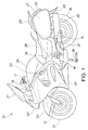
- Fig. 1 is a lateral view of a motorcycle employing a wiring connector according to the present invention.
- a motorcycle 10 includes a handlebar 11, a front fork 12 and a front wheel 13 steered by the handlebar 11, which are disposed in the front portion 18 of a vehicle body.
- a body frame 14 is disposed along from the front portion 18 to the middle portion 19 of the vehicle body and an engine (not shown) is mounted on the body frame 14.
- a swing arm 15 is swingably attached to the lower portion of the body frame 14 and a rear wheel 16 is attached to the rear end of the swing arm 15.
- reference numeral 21 denotes a windscreen, 62 a headlamp, 23 a front fender, 24 a cowling, 25 a fuel tank, 26 a seat, 27 a saddle bag, 28 a stand, 29 a grab rail, 31 an exhaust pipe, 32 a muffler, 33 a rear fender, and 50 a tail lamp.
- reference numeral 30 denotes a wiring connector.
- this wiring connector (branch connector) 30 is a connector capable of increasing the number of interconnections that can be simultaneously connected thereto and expanding its applications.
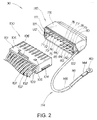
- Fig. 2 is a perspective view of the wiring connector of the present invention with an I-shaped terminal group 113 (see Fig. 5) omitted, described later.
- a wiring connector 30 is composed of a male connector (plug) 100 and a female connector (socket) 110 adapted to receive the male connector 100.
- This wiring connector 30 is adapted to assemble the grounding wires of a plurality of connection equipment into several grounding wires, which are connected to a predetermined earth point.
- Fig. 3 is a wiring block diagram of the motorcycle employing the wiring connector according to the present invention.
- a wiring system 40 is shown in Fig. 3. Incidentally, this wiring system 40 is one example of use of the wiring connector 30.
- reference numeral 41 denotes an up-down switch, 42 an option terminal, 43 a water temperature sensor, 44 a screen relay, 45 a right rear winker, 46 a first fan, 47 a second fan, 48 a stop lamp relay, 49 a left rear winker, 50 a tail lamp, 51 a stop lamp, 52 a low beam head lamp relay, 53 high beam head lamp relay, 54 a fuel pump, 55 an electrically driven screen, 56 a horn, 57 a bank angle sensor, 58 a meter, 59 a right front winker, 61 a left front winker, and 62 a head lamp.
- connection equipment 41 to 62 the components denoted by reference numerals 41 through 62 are generically named "the connection equipment 41 to 62" in this specification.
- the wiring system 40 is such that the grounding ends of the connection equipment 41 to 62 are connected to respective terminals of the wiring connector 30, namely, "a 1st terminal” 71 to "a 9th terminal” 79 and “a 13th terminal” 83 to "a 16th terminal” 86, and +B ends of the connection equipment 41 to 62 are connected to +B (plus) terminal 65 of a battery 64 or a power supply.
- Reference numeral 66 denotes the ground (minus) of the battery 64.
- a 10th terminal” 80 as a terminal, "a 11th terminal” 81 as a new connection terminal, and “a 12th terminal” 82 as a terminal serve each as an output side grounding wire which collects input side grounding wires received from "the 1st terminal” 71 though “the 9th terminal” 79 and “the 13th terminal” 83 through “the 16th terminal” 86 as base terminal side grounding wires and outputs them.
- the 1st terminal” 71 through “the 16th terminal” 86 are terminals electrically and mechanically connected to one another.
- the 17th terminal” 87 through “the 21st terminal” are terminals electrically and mechanically connected to one another and separated from “the 1st terminal” 71 through “the 16th terminal” 86.
- the 17th terminal” 87 through “the 21st terminal” 91 are used as sensor grounding terminals in the present embodiment. Note that “the 17th terminal” 87 through “the 21st terminal” 91 may be used as circuit terminals other than the grounding terminals.
- the detailed shape of the wiring connector 30 will be described below.
- Fig. 4 is an exploded perspective view of the male connector of the wiring connector according to the present invention.
- the male connector 100 is composed of a male housing 101 made of an insulator and cables 102 ... (symbol "" denotes plurality, and the same holds true of the following) fixedly inserted into the male housing 101.
- the male housing 101 includes tubelike parts 103 ... adapted to fixedly press fit the cables 102 ..., rails 104, 104 (one of the rails 104 is omitted) used to insert the male housing 101 into the female connector 110 in a predetermined direction, locking claws 105, 105 adapted to be locked to the female connector 110, and an engaging part 106 used to withdraw the male housing 101 from the female connector 110 (see Fig. 2).
- Each of the cables 102 is provided with a male terminal 107 adapted to be fixedly inserted into the tubelike part 103.
- Fig. 5 is an exploded perspective view of the female connector of the wiring connector according to the present invention.
- the female connector 110 includes a connector housing 111 made of an insulator, a U-shaped terminal group 112, an I-shaped terminal group 113, a harness 114, and a heat shrinkage tube 115.
- the U-shaped terminal group 112 is in an almost-U-shape and is adapted to be fixedly press fitted (attached) to the connector housing 111.
- the I-shaped terminal group 113 is formed linear (I-shaped) as a row of independent terminals and is adapted to be fixedly press fitted (attached) to the connector housing 111.
- the harness 114 is connected to "the 11th terminal" 81 as a new connector terminal (terminal) of the U-shaped terminal group 112.
- the heat shrinkage tube 115 shields retaining holes 123, 123 and a hole portion 125 and supports the harness 114 by being overlaid on the sidewalls 124 of the connector housing 111.
- the connector housing 111 is formed with a storage recess portion 121, guide portions 122, 122 retaining holes 123, 123 a hole portion 125 and press fit portions 126 (see Fig. 6).
- the storage recess portion 121 is adapted to store the U-shaped terminal group 112 and the I-shaped terminal group 113.
- the guide portions 122, 122 are adapted to guide the rails 104, 104 of the male housing 101.
- the retaining holes 123, 123 are adapted to retain the locking claws 105, 105 of the male housing 101.
- the hole portion 125 is adapted to extend the harness 114 and "the 11th terminal" 81 out of the connector housing 111 to the exterior thereof.
- "the 11th terminal" 81 of the U-shaped terminal group 112 is formed at a turndown 127.
- the U-shaped terminal group 112 is formed of "the 1st terminal” 71 through “the 16th terminal” 86, a base 131 adapted to electrically and mechanically connect “the 1st terminal” 71 through “the 16th terminal” 86, press fit pins 132 ... formed at the base 131 so as to correspond to "the 1st terminal” 71 through “the 16th terminal” 86, and the turndown 127 adapted to turn down the U-shaped group 112 in a U-shaped manner.
- the I-shaped terminal group 113 is formed of "the 17th terminal” 87 through “the 21st terminal” 91, a base 133 adapted to electrically and mechanically connect “the 17th terminal” 87 through “the 21st terminal” 91, and press fit pins 134 ... formed at the base 133 so as to correspond to "the 17th terminal” 87 through “the 21st terminal” 91.
- the 1st terminal” 71 through “the 10th terminal” 80 of the U-shaped terminal group 112 constitute a first terminal row 137.
- "The 12th terminal” 82 through “the 16th terminal” 86 of the U-shaped terminal group 112 and “the 17th terminal” 87 through “the 21st terminal” 91 of the I-shaped terminal group 113 constitute a second terminal row 138.
- the terminal rows 137, 138 formed of the plurality of the terminals 71 to 91 attached to the connector housing 111, and a plurality of stages of the terminal rows 137, 138 are arranged in the connector housing 111, if adjacent terminal rows included in the plurality of stages of the terminal rows 137, 138 are called a first terminal row 137 and a second terminal row 138, at least the bases 131 of the first terminal row 137 and the second terminal row 138 are formed integrally with each other and the turndown 127 is formed to attach the first and second terminal rows 137, 138 to the connector housing 111, and "the 11th terminal" 81 or a new connection terminal is formed at the turndown 127.
- the variations of the wiring connector can be increased. If the number of stages of terminal rows can be arbitrarily increased, preferably the number of interconnections connectable at the same time can be increased.
- the bases 131 of at least the first terminal row 137 and the second terminal row 138 adjacent to each other are formed integrally with each other, the number of terminals of the plurality of terminal rows 137, 138 can be freely set. Consequently, the variations of the wiring connector 30 can be increased.
- the bases 131 of at least the first terminal row 137 and the second terminal row 138 adjacent to each other are formed integrally with each other, the number of stages of the terminal rows can be arbitrarily increased. As a result, the number of wires connectable at the same time can be increased.
- the turndown 127 is formed to attach the first and second terminal rows 137, 138 to the connector housing 111, and the new connection terminal 81 is formed at the turndown 127, the use applications of the wiring connector 30 can be increased.
- the position of new connection terminal can be identified easily.
- the wiring connector 30 is formed such that the number of the terminals included in the first terminal row 137 electrically conducted to each other is made different from the number of the terminals included in the second terminal row 138 electrically conducted to the first terminal rows 137.
- the wiring connector 30 is formed such that the number of the terminals included in the first terminal row 137 electrically conducted to each other is made different from the number of the terminals included in the second terminal row 138 electrically conducted to the first terminal rows 137, the wiring connector can be realized which is adaptable to arbitrary use applications.
- the wiring connector 30 is configured such that "the 11th terminal" 81 or the new connection terminal is an output side terminal to the ground, serving as a base terminal of the branch connector.
- the new connection terminal 81 is formed at the turndown 127, the position of the output side terminal can be identified easily.
- the wiring connector 30 is configured such that the terminals ("the 10th terminal” 80 and “the 12th terminal” 82) near the new connection terminal 81 are base terminals (output side terminals in the embodiment) and the remaining terminals ("the 1st terminal” 71 through “the 9th terminal” 79 and “the 13th terminal” 83 through “the 16th terminal” 86) are branch terminals (input side terminals in the embodiment). Therefore, the rated power consumption of the wiring connector can be improved. In addition, even if one of the base terminals develops trouble, other base terminals can complement the function of the base terminal in trouble. Consequently, the wiring connector can be improved in reliability.
- the wiring connector 30 is configured such that the independent terminal row (I-shaped terminal row) 113 electrically independent of "the 12th terminal” through “the 16th terminal” electrically and mechanically connected to the first terminal row 137 is disposed in the second terminal row 138, the space of the connector housing 111 can be utilized effectively.
- the wiring connector 30 has the hole portion 125 formed in the sidewall 124 of the connector housing 111. "The 11th terminal" 81 or the new connection terminal is introduced to the exterior of the connector housing 111 through the hole portion 125 and the harness 114 is extended from the connection terminal 81. Therefore, the degree of freedom of the wiring can be increased in terms of design and the use applications of the connection terminals 81 can be increased.
- the wiring connector 30 intends to reinforce the power supply ground by allowing the new connection terminal 81 and the terminals ("the 10th terminal” 80 and "the 12th terminal” 82) near the new connection terminal 81 to serve as the base terminals of the branch connector (wiring connector).
- Fig 6 is a plan view of the female connector of the wiring connector according to the present invention.
- the harness 114 is composed of a harness body 141, a harness side terminal 142 attached to one end of the harness body 141, a lug terminal 143 attached to the other end of the harness body 141, a tube 144 covering the lug terminal 143 and the other end of the harness body 141, and a protection tube 145 covering the harness body 141.
- the wiring connector 30 (see Fig. 2) has the hole portion 125 formed in the sidewall 124 (see Fig. 5) of the connector housing 111, "the 11th terminal" 81 or the new connection terminal 81 is introduced to the exterior of the connector housing 111 through the hole portion 125 and the harness 114 is extended from the connection terminal 81.
- the hole portion 125 is formed in the sidewall 124 of the connector housing 111, "the 11th terminal" 81 or the new connection terminal 81 is introduced to the exterior of the connector housing 111 through the hole portion 125 and the harness 114 is extended from the connection terminal 81, whereby the use applications of the connection terminal 81 can be increased.
- Figs. 7 (a) and 7(b) are comparatively explanatory views of a terminal group of a conventional wiring connector and the U-shaped terminal group of the wiring connector according to the present invention.
- Fig. 7(a) depicts a U-shaped terminal group 212 by way of comparative example and
- Fig. 7(b) depicts the U-shaped terminal group 112 of the present embodiment.
- the U-shaped terminal group 212 is formed by setting up a plurality of terminals 214 ... , 215 ... , 216 ... from a bottom portion 213. Accordingly, it is difficult to form three or more stages of terminal rows, that is, it is impossible to realize a wiring connector having multiple stages of terminal rows.
- the U-shaped terminal group 112 is formed by connecting the terminals 71 through 86 continuously. Accordingly, a multiple stage wiring connector having two or more terminal rows can be realized by a plurality of turndowns such as the turndown 127.
- Figs. 8 (a) and 8(b) are comparatively explanatory views of the terminal group of a conventional wiring connector and the U-shaped terminal group of the wiring connector according to the present invention, illustrating the developed states thereof.
- Fig. 8 (a) is exemplification in a case of manufacturing the U-shaped terminal group having the same shape through the conventional bending and illustrates the U-shaped terminal group 212 as a comparative example.
- Fig. 8(b) illustrates the U-shaped terminal group 112 according to the embodiment of the present invention.
- the U-shaped terminal group 212 is formed by setting up a plurality of terminals 214 ..., 215 ..., 216 from a bottom portion 213.
- waste portions of the material 217, 218, and 219 are produced to degrade efficiency and to increase the cost of the wiring connector in some cases.
- the U-shaped terminal group 112 is formed by allowing the base portion 131 to connect the terminals 71 through 86.
- the material can be utilized effectively to reduce the cost of the wiring connector 30 and to improve the productivity of the wiring connector 30.
- a long terminal group is cut away as appropriate into a variety of terminal groups whose numbers of terminals are different from one another, which can be used for a wiring connector having a plurality of rows.
- the wiring connector according to the present invention is configured such that "the 1st terminal” 71 through “the 21st terminal” have the same shape as shown in Fig. 5, the wiring connector of the invention is not limited this configuration.
- "the 11th terminal” 81 may be formed thicker so as to increase its current capacity.
- the wiring connector according to the present invention is configured to have the two stages of terminal rows 137, 138 as shown in Fig. 5, the wiring connector of the invention is not limited to this configuration.
- the number of the stages of terminal rows may be three or more.
- the wiring connector according to the present invention is configured such that the independent terminal row (I-shaped terminal group) 113 independent electrically of the second terminal row 138 is arranged on the same plane as the second terminal row 138.
- the wiring connector of the invention is not limited to this configuration, that is, the independent terminal row independent electrically of the other terminal rows may be arranged on another terminal row.
- the invention is configured such that the base terminal is arranged on the ground output side and the branch terminal is arranged on the ground input side, the invention is not limited to this configuration.
- the configuration may be such that the base terminal is arranged on the ground input side and the branch terminal is arranged on the ground output side.
- the present invention uses the wiring connector for the grounding circuit
- the application is not limited to the grounding circuit.
- the application is arbitrary.
- the wiring connector may be used in such a way as to cut away or bend the press fit pin 132 just below the turndown 127. This makes it possible to divert a conventional connector housing without a socket for the press fit pin 132 to the present invention by forming the hole portion 125 in the conventional connector housing.
- the wiring connector according to the present invention is preferably applied to relatively large motorcycles having many various accessories.
Landscapes
- Engineering & Computer Science (AREA)
- Mechanical Engineering (AREA)
- Connector Housings Or Holding Contact Members (AREA)
- Coupling Device And Connection With Printed Circuit (AREA)
- Connection Or Junction Boxes (AREA)
Abstract
Description
- The present invention relates to a wiring connector capable of collectively outputting a plurality of input side interconnections.
- Many various types of wiring connectors have been put to practical use for any purpose.
- For example, if a plurality of input side interconnections are collectively outputted, a wiring connector for collection is used as a practical wiring connector. A branch connector needs only to be used in order to branch single wiring into a plurality of output interconnections. Thus, a wiring connector needs only to be selected in accordance with intended use from a practical standpoint.
- A known example of such a wiring connector is provided with two stages of a plurality of terminal rows. (Refer to, e.g., Japanese Utility Model Publication No. Sho 63-33509 (Pages. 4 and 5, Figs. 4 and 5).
- The conventional wiring connector is composed of a connector housing made of an insulator and a terminal group arranged in the connector housing. This terminal group is integrally formed of a plurality of terminals. More specifically, the terminal group is formed into a first terminal row and a second terminal row each having a plurality of terminals by folding it back at the center portion thereof.
- For example, if the conventional wiring connector includes the first terminal row and the second terminal row which have terminals different in number from each other, the terminal groups are different in shape from each other. Therefore, the wiring connector is hard to manufacture, so that a problem arises in that a restriction is imposed on the number of the terminals included in the plurality of terminal rows.
- In addition, the wiring connector is formed to include the first and the second terminal row each having a plurality of terminals by folding it back at the center portion thereof. This provides a drawback that it is difficult to integrally form more than two stages of terminals.
- Accordingly, it is desired to provide a wiring connector capable of preventing the shapes of terminal groups from differing from each other and arbitrarily increasing the number of stages of terminal rows.
- It is an object of the present invention to provide a wiring connector capable of solving the problem in that terminal groups are different in shape from each other so as to become difficult to manufacture, and freely setting the number of terminals included in a plurality of terminal rows. In addition, it is another object of the present invention is to provide a wiring connector capable of solving the problem in that three or more stages of terminals cannot be integrally formed, thereby arbitrarily increasing the number of terminal rows.
- The invention pertaining to
claim 1 is characterized in that, in a wiring connector including: - a connector housing made of an insulator; and a plurality of stages of terminal rows arranged in the connector housing, the terminal rows each being formed of a plurality of terminals connected to each other; if terminal rows adjacent to each other among the plurality of terminal rows are called a first terminal row and a second terminal row, respective bases of at least the first and second terminal rows adjacent to each other are formed integrally with each other, a turndown adapted to attach the first and second terminal rows to the connector housing is formed by folding back the bases, and a new connection terminal is formed at the turndown.
- For example, if it is possible to freely set the number of terminals included in the plurality of terminal rows, preferably the variations of the wiring connector can be increased. If the number of stages of terminal rows can be arbitrarily increased, preferably the number of interconnections connectable at the same time can be increased.
- More specifically, since the bases of at least the first terminal row and the second terminal row adjacent to each other are formed integrally with each other, the number of terminals of the plurality of terminal rows can be freely set. In addition, since the bases of at least the first terminal row and the second terminal row adjacent to each other are formed integrally with each other, the number of stages of the terminal rows can be arbitrarily increased.
- Further, since the turndown is formed to attach the first and second terminal rows to the connector housing, and the new connection terminal is formed at the turndown, the use applications of the wiring connector can be increased.
- The invention pertaining to claim 2 is characterized in that the first terminal row is made different in the number of terminals from the second terminal row.
- Since the first terminal row is made different in the number of terminals from the second terminal row, the wiring connector can be realized which is adaptable to arbitrary use applications.
- The invention pertaining to
claim 3 is characterized in that the new connection terminal serves as a base terminal. Since the new connection terminal is formed at the turndown, the position of the output side terminal can be identified easily, facilitating wiring. - The invention pertaining to claim 4 is characterized in that the new connection terminal and a terminal near the new connection terminal serve as base terminals and the remaining terminals serve as branch terminals.
- Since the new connection terminal and a terminal near the new connection terminal serve as base terminals and the remaining terminals serve as branch terminals, those positions can be identified easily and the rated power consumption of the wiring connector can be improved. In addition, even if one of the base terminals develops trouble, another base terminal can complement the function of the base terminal in trouble.
- The invention pertaining to claim 5 is characterized in that an independent terminal row independent electrically of the first terminal row and the second terminal row is arranged on the same plane as the first terminal row or the second terminal row.
- Since the independent terminal row independent electrically of the first terminal row and the second terminal row is arranged on the same plane as the first terminal row or the second terminal row, the space of the connector housing can be utilized effectively.
- Claim 6 is characterized in that a hole portion is formed in a sidewall of the connector housing, the new connection terminal is introduced to the exterior of the connector housing through the hole portion, and a harness is extended from the connection terminal.
- Since the hole portion is formed in a sidewall of the connector housing, the new connection terminal is introduced to the exterior of the connector housing through the hole portion, and a harness is extended from the connection terminal, the degree of freedom of the wiring can be increased and the use applications of the connection terminal can be increased.
-
Claim 7 is characterized in that the new connection terminal and a terminal near the new connection terminal serve as base terminals. - Since the new connection terminal and the terminal near the new connection terminal serve as base terminals, the power supply ground can be intended to be reinforced.
- In the invention according to
claim 1, since the bases of at least the first terminal row and the second terminal row adjacent to each other are formed integrally with each other, the number of terminals of the plurality of terminal rows can be freely set. This leads to an advantage that the variations of the wiring connector can be increased. In addition, since the bases of at least the first terminal row and the second terminal row adjacent to each other are formed integrally with each other, the number of stages of the terminal rows can be arbitrarily increased. This leads to an advantage that the number of interconnections connectable to each other at the same time can be increased. - Further, since the turndown is formed to attach the first and second terminal rows to the connector housing, and the new connection terminal is formed at the turndown, the use applications of the wiring connector can be advantageously increased.
- In the invention according to claim 2, since the first terminal row is made different in the number of terminals from the second terminal row, the wiring connector can be realized which is adaptable to arbitrary use applications.
- In the invention according to
claim 3, since the new connection terminal is made to serve as a base terminal, the new connection terminal is located at the turndown. This leads to an advantage that its position can be identified easily, facilitating wiring. - In the invention according to claim 4, since the new connection terminal and a terminal near the new connection terminal serve as base terminals and the remaining terminals serve as branch terminals, those positions can be identified easily and the rated power consumption of the wiring connector can be improved. In addition, even if one of the base terminals develops trouble, another base terminal can complement the function of the base terminal in trouble. This leads to an advantage that the reliability of the wiring connector can be improved.
- In the invention according to claim 5, since the independent terminal row independent electrically of the first terminal row and the second terminal row is arranged on the same plane as the first terminal row or the second terminal row, it is advantageous that the space of the connector housing can be utilized effectively.
- In the invention according to claim 6, since the hole portion is formed in a sidewall of the connector housing, the new connection terminal is introduced to the exterior of the connector housing through the hole portion, and a harness is extended from the connection terminal, it is advantageous that the degree of freedom of the wiring can be increased and the use applications of the connection terminal can be increased.
- In the invention according to
claim 7, since the new connection terminal and the terminal near the new connection terminal are made to serve as base terminals, the power supply ground can be advantageously intended to be reinforced. -
- Fig. 1 is a side view of a motorcycle employing a wiring connector according to the present invention.
- Fig. 2 is a perspective view of the wiring connector according to the present invention.
- Fig. 3 is a wiring block diagram of the motorcycle employing the wiring connector according to the present invention.
- Fig. 4 is an exploded perspective view of a male connector of the wiring connector according to the present invention.
- Fig. 5 is an exploded perspective view of a female connector of the wiring connector according to the present invention.
- Fig. 6 is a plan view of the female connector of the wiring connector according to the present invention.
- Fig. 7a and 7b include comparatively explanatory views of the terminal group of a conventional wiring connector and the U-shaped terminal group of the wiring connector according to the present invention.
- Fig. 8a and 8b include comparatively explanatory views of the terminal group of a conventional wiring connector and the U-shaped terminal group of the wiring connector according to the present invention, illustrating the developed shapes thereof.
- 30 ... wiring connector, 71 to 79 ... branch terminal ("1st terminal" to "9th terminal"), 80 ... base terminal ("10th terminal"), 81 ... new connection terminal (base terminal or "11th terminal"), 82 ... base terminal ("12th terminal"), 83 to 86 ... branch terminal ("13th terminal" to "16th terminal"), 111 ... connector housing, 113 ... independent terminal row (I-shaped terminal group), 114 ... harness, 127 ... turndown, 131 ... base, 137, 138 ... first and second terminal rows.
- Preferred embodiments of the present invention will be below described with reference to the accompanying drawings. Incidentally, the drawings shall be viewed from the direction of reference numerals.
- Fig. 1 is a lateral view of a motorcycle employing a wiring connector according to the present invention. In the figure, a
motorcycle 10 includes a handlebar 11, afront fork 12 and afront wheel 13 steered by the handlebar 11, which are disposed in thefront portion 18 of a vehicle body. Abody frame 14 is disposed along from thefront portion 18 to themiddle portion 19 of the vehicle body and an engine (not shown) is mounted on thebody frame 14. Aswing arm 15 is swingably attached to the lower portion of thebody frame 14 and arear wheel 16 is attached to the rear end of theswing arm 15. - In the figure,
reference numeral 21 denotes a windscreen, 62 a headlamp, 23 a front fender, 24 a cowling, 25 a fuel tank, 26 a seat, 27 a saddle bag, 28 a stand, 29 a grab rail, 31 an exhaust pipe, 32 a muffler, 33 a rear fender, and 50 a tail lamp. - In addition,
reference numeral 30 denotes a wiring connector. As described later, this wiring connector (branch connector) 30 is a connector capable of increasing the number of interconnections that can be simultaneously connected thereto and expanding its applications. - Fig. 2 is a perspective view of the wiring connector of the present invention with an I-shaped terminal group 113 (see Fig. 5) omitted, described later.
- A
wiring connector 30 is composed of a male connector (plug) 100 and a female connector (socket) 110 adapted to receive themale connector 100. Thiswiring connector 30 is adapted to assemble the grounding wires of a plurality of connection equipment into several grounding wires, which are connected to a predetermined earth point. - Specific examples of how the
wiring connector 30 is used will be described with reference to the next figure. - Fig. 3 is a wiring block diagram of the motorcycle employing the wiring connector according to the present invention. A
wiring system 40 is shown in Fig. 3. Incidentally, thiswiring system 40 is one example of use of thewiring connector 30. - In the figure,
reference numeral 41 denotes an up-down switch, 42 an option terminal, 43 a water temperature sensor, 44 a screen relay, 45 a right rear winker, 46 a first fan, 47 a second fan, 48 a stop lamp relay, 49 a left rear winker, 50 a tail lamp, 51 a stop lamp, 52 a low beam head lamp relay, 53 high beam head lamp relay, 54 a fuel pump, 55 an electrically driven screen, 56 a horn, 57 a bank angle sensor, 58 a meter, 59 a right front winker, 61 a left front winker, and 62 a head lamp. - Incidentally, the components denoted by
reference numerals 41 through 62 are generically named "theconnection equipment 41 to 62" in this specification. - The
wiring system 40 is such that the grounding ends of theconnection equipment 41 to 62 are connected to respective terminals of thewiring connector 30, namely, "a 1st terminal" 71 to "a 9th terminal" 79 and "a 13th terminal" 83 to "a 16th terminal" 86, and +B ends of theconnection equipment 41 to 62 are connected to +B (plus)terminal 65 of abattery 64 or a power supply.Reference numeral 66 denotes the ground (minus) of thebattery 64. - "A 10th terminal" 80 as a terminal, "a 11th terminal" 81 as a new connection terminal, and "a 12th terminal" 82 as a terminal serve each as an output side grounding wire which collects input side grounding wires received from "the 1st terminal" 71 though "the 9th terminal" 79 and "the 13th terminal" 83 through "the 16th terminal" 86 as base terminal side grounding wires and outputs them.
- Incidentally, "the 1st terminal" 71 through "the 16th terminal" 86 are terminals electrically and mechanically connected to one another.
- In addition, "the 17th terminal" 87 through "the 21st terminal" are terminals electrically and mechanically connected to one another and separated from "the 1st terminal" 71 through "the 16th terminal" 86. "The 17th terminal" 87 through "the 21st terminal" 91 are used as sensor grounding terminals in the present embodiment. Note that "the 17th terminal" 87 through "the 21st terminal" 91 may be used as circuit terminals other than the grounding terminals.
- The detailed shape of the
wiring connector 30 will be described below. - Fig. 4 is an exploded perspective view of the male connector of the wiring connector according to the present invention. The
male connector 100 is composed of amale housing 101 made of an insulator andcables 102 ... (symbol "..." denotes plurality, and the same holds true of the following) fixedly inserted into themale housing 101. - The
male housing 101 includestubelike parts 103 ... adapted to fixedly press fit thecables 102 ..., rails 104, 104 (one of therails 104 is omitted) used to insert themale housing 101 into thefemale connector 110 in a predetermined direction, lockingclaws female connector 110, and anengaging part 106 used to withdraw themale housing 101 from the female connector 110 (see Fig. 2). - Each of the
cables 102 is provided with amale terminal 107 adapted to be fixedly inserted into thetubelike part 103. - Fig. 5 is an exploded perspective view of the female connector of the wiring connector according to the present invention. The
female connector 110 includes a connector housing 111 made of an insulator, a U-shapedterminal group 112, an I-shapedterminal group 113, aharness 114, and aheat shrinkage tube 115. TheU-shaped terminal group 112 is in an almost-U-shape and is adapted to be fixedly press fitted (attached) to the connector housing 111. The I-shapedterminal group 113 is formed linear (I-shaped) as a row of independent terminals and is adapted to be fixedly press fitted (attached) to the connector housing 111. Theharness 114 is connected to "the 11th terminal" 81 as a new connector terminal (terminal) of theU-shaped terminal group 112. Theheat shrinkage tube 115shields retaining holes hole portion 125 and supports theharness 114 by being overlaid on thesidewalls 124 of the connector housing 111. - The connector housing 111 is formed with a
storage recess portion 121, guideportions holes 123, 123 ahole portion 125 and press fit portions 126 (see Fig. 6). Thestorage recess portion 121 is adapted to store theU-shaped terminal group 112 and the I-shapedterminal group 113. Theguide portions rails male housing 101. The retaining holes 123, 123 are adapted to retain the lockingclaws male housing 101. Thehole portion 125 is adapted to extend theharness 114 and "the 11th terminal" 81 out of the connector housing 111 to the exterior thereof. Incidentally, "the 11th terminal" 81 of theU-shaped terminal group 112 is formed at a turndown 127. - The
U-shaped terminal group 112 is formed of "the 1st terminal" 71 through "the 16th terminal" 86, a base 131 adapted to electrically and mechanically connect "the 1st terminal" 71 through "the 16th terminal" 86, press fit pins 132 ... formed at the base 131 so as to correspond to "the 1st terminal" 71 through "the 16th terminal" 86, and the turndown 127 adapted to turn down theU-shaped group 112 in a U-shaped manner. - The I-shaped
terminal group 113 is formed of "the 17th terminal" 87 through "the 21st terminal" 91, a base 133 adapted to electrically and mechanically connect "the 17th terminal" 87 through "the 21st terminal" 91, and press fit pins 134 ... formed at the base 133 so as to correspond to "the 17th terminal" 87 through "the 21st terminal" 91. - "The 1st terminal" 71 through "the 10th terminal" 80 of the
U-shaped terminal group 112 constitute a firstterminal row 137. "The 12th terminal" 82 through "the 16th terminal" 86 of theU-shaped terminal group 112 and "the 17th terminal" 87 through "the 21st terminal" 91 of the I-shapedterminal group 113 constitute a secondterminal row 138. - In other words, the following can be said. In the
wiring connector 30 in which the connector housing 111 is formed of an insulator, theterminal rows terminals 71 to 91 attached to the connector housing 111, and a plurality of stages of theterminal rows terminal rows terminal row 137 and a secondterminal row 138, at least thebases 131 of the firstterminal row 137 and the secondterminal row 138 are formed integrally with each other and the turndown 127 is formed to attach the first and secondterminal rows - For instance, if it is possible to freely set the number of terminals included in a plurality of terminal rows, preferably the variations of the wiring connector can be increased. If the number of stages of terminal rows can be arbitrarily increased, preferably the number of interconnections connectable at the same time can be increased.
- In other words, since the
bases 131 of at least the firstterminal row 137 and the secondterminal row 138 adjacent to each other are formed integrally with each other, the number of terminals of the plurality ofterminal rows wiring connector 30 can be increased. In addition, since thebases 131 of at least the firstterminal row 137 and the secondterminal row 138 adjacent to each other are formed integrally with each other, the number of stages of the terminal rows can be arbitrarily increased. As a result, the number of wires connectable at the same time can be increased. - Further, since the turndown 127 is formed to attach the first and second
terminal rows new connection terminal 81 is formed at the turndown 127, the use applications of thewiring connector 30 can be increased. In addition, when a particular input terminal or output terminal is connected to a new connection terminal, the position of new connection terminal can be identified easily. - Also it can be said that the
wiring connector 30 is formed such that the number of the terminals included in the firstterminal row 137 electrically conducted to each other is made different from the number of the terminals included in the secondterminal row 138 electrically conducted to the firstterminal rows 137. - Since the
wiring connector 30 is formed such that the number of the terminals included in the firstterminal row 137 electrically conducted to each other is made different from the number of the terminals included in the secondterminal row 138 electrically conducted to the firstterminal rows 137, the wiring connector can be realized which is adaptable to arbitrary use applications. - As shown in Fig. 3, the
wiring connector 30 is configured such that "the 11th terminal" 81 or the new connection terminal is an output side terminal to the ground, serving as a base terminal of the branch connector. - For example, since the
new connection terminal 81 is formed at the turndown 127, the position of the output side terminal can be identified easily. - As shown in Fig. 3, the
wiring connector 30 is configured such that the terminals ("the 10th terminal" 80 and "the 12th terminal" 82) near thenew connection terminal 81 are base terminals (output side terminals in the embodiment) and the remaining terminals ("the 1st terminal" 71 through "the 9th terminal" 79 and "the 13th terminal" 83 through "the 16th terminal" 86) are branch terminals (input side terminals in the embodiment). Therefore, the rated power consumption of the wiring connector can be improved. In addition, even if one of the base terminals develops trouble, other base terminals can complement the function of the base terminal in trouble. Consequently, the wiring connector can be improved in reliability. - Since the
wiring connector 30 is configured such that the independent terminal row (I-shaped terminal row) 113 electrically independent of "the 12th terminal" through "the 16th terminal" electrically and mechanically connected to the firstterminal row 137 is disposed in the secondterminal row 138, the space of the connector housing 111 can be utilized effectively. - The
wiring connector 30 has thehole portion 125 formed in thesidewall 124 of the connector housing 111. "The 11th terminal" 81 or the new connection terminal is introduced to the exterior of the connector housing 111 through thehole portion 125 and theharness 114 is extended from theconnection terminal 81. Therefore, the degree of freedom of the wiring can be increased in terms of design and the use applications of theconnection terminals 81 can be increased. - As shown in Fig. 3, the
wiring connector 30 intends to reinforce the power supply ground by allowing thenew connection terminal 81 and the terminals ("the 10th terminal" 80 and "the 12th terminal" 82) near thenew connection terminal 81 to serve as the base terminals of the branch connector (wiring connector). - Fig 6 is a plan view of the female connector of the wiring connector according to the present invention.
- The
harness 114 is composed of aharness body 141, aharness side terminal 142 attached to one end of theharness body 141, alug terminal 143 attached to the other end of theharness body 141, atube 144 covering thelug terminal 143 and the other end of theharness body 141, and aprotection tube 145 covering theharness body 141. - It can be said that the wiring connector 30 (see Fig. 2) has the
hole portion 125 formed in the sidewall 124 (see Fig. 5) of the connector housing 111, "the 11th terminal" 81 or thenew connection terminal 81 is introduced to the exterior of the connector housing 111 through thehole portion 125 and theharness 114 is extended from theconnection terminal 81. - That is to say, the
hole portion 125 is formed in thesidewall 124 of the connector housing 111, "the 11th terminal" 81 or thenew connection terminal 81 is introduced to the exterior of the connector housing 111 through thehole portion 125 and theharness 114 is extended from theconnection terminal 81, whereby the use applications of theconnection terminal 81 can be increased. - Figs. 7 (a) and 7(b) are comparatively explanatory views of a terminal group of a conventional wiring connector and the U-shaped terminal group of the wiring connector according to the present invention. Fig. 7(a) depicts a U-shaped
terminal group 212 by way of comparative example and Fig. 7(b) depicts theU-shaped terminal group 112 of the present embodiment. - In Fig. 7(a), the
U-shaped terminal group 212 is formed by setting up a plurality ofterminals 214 ... , 215 ... , 216 ... from abottom portion 213. Accordingly, it is difficult to form three or more stages of terminal rows, that is, it is impossible to realize a wiring connector having multiple stages of terminal rows. - In Fig. 7(b), the
U-shaped terminal group 112 is formed by connecting theterminals 71 through 86 continuously. Accordingly, a multiple stage wiring connector having two or more terminal rows can be realized by a plurality of turndowns such as the turndown 127. - Figs. 8 (a) and 8(b) are comparatively explanatory views of the terminal group of a conventional wiring connector and the U-shaped terminal group of the wiring connector according to the present invention, illustrating the developed states thereof. Fig. 8 (a) is exemplification in a case of manufacturing the U-shaped terminal group having the same shape through the conventional bending and illustrates the
U-shaped terminal group 212 as a comparative example. Fig. 8(b) illustrates theU-shaped terminal group 112 according to the embodiment of the present invention. - In Fig. 8(a), the
U-shaped terminal group 212 is formed by setting up a plurality ofterminals 214 ..., 215 ..., 216 from abottom portion 213. Thus, waste portions of thematerial - In Fig. 8(b), the
U-shaped terminal group 112 is formed by allowing thebase portion 131 to connect theterminals 71 through 86. Thus, the material can be utilized effectively to reduce the cost of thewiring connector 30 and to improve the productivity of thewiring connector 30. - In addition, a long terminal group is cut away as appropriate into a variety of terminal groups whose numbers of terminals are different from one another, which can be used for a wiring connector having a plurality of rows.
- Incidentally, while the wiring connector according to the present invention is configured such that "the 1st terminal" 71 through "the 21st terminal" have the same shape as shown in Fig. 5, the wiring connector of the invention is not limited this configuration. For example, "the 11th terminal" 81 may be formed thicker so as to increase its current capacity.
- While the wiring connector according to the present invention is configured to have the two stages of
terminal rows - The wiring connector according to the present invention is configured such that the independent terminal row (I-shaped terminal group) 113 independent electrically of the second
terminal row 138 is arranged on the same plane as the secondterminal row 138. However, the wiring connector of the invention is not limited to this configuration, that is, the independent terminal row independent electrically of the other terminal rows may be arranged on another terminal row. - While the invention is configured such that the base terminal is arranged on the ground output side and the branch terminal is arranged on the ground input side, the invention is not limited to this configuration. The configuration may be such that the base terminal is arranged on the ground input side and the branch terminal is arranged on the ground output side.
- While the present invention uses the wiring connector for the grounding circuit, the application is not limited to the grounding circuit. The application is arbitrary.
- In addition, the wiring connector may be used in such a way as to cut away or bend the
press fit pin 132 just below the turndown 127. This makes it possible to divert a conventional connector housing without a socket for thepress fit pin 132 to the present invention by forming thehole portion 125 in the conventional connector housing. - The wiring connector according to the present invention is preferably applied to relatively large motorcycles having many various accessories.
Claims (7)
- A wiring connector comprising:- a connector housing (111) made of an insulator; and- a plurality of stages of terminal rows (137, 138) arranged in the connector housing, the terminal rows each being formed of a plurality of terminals (71 to 91) connected to each other;wherein, if terminal rows adjacent to each other among the plurality of terminal rows (137, 138) are called a first terminal row (137) and a second terminal row (138), respective bases of at least the first and second terminal rows adjacent to each other are formed integrally with each other, a turndown (127) adapted to attach the first and second terminal rows (137, 138) to the connector housing (111) is formed by folding back the bases, and a new connection terminal (81) is formed at the turndown (127).
- The wiring connector according to claim 1, wherein the first terminal row (137) is made different in the number of terminals from the second terminal row (138).
- The wiring connector according to claim 1, wherein the new connection terminal (81) serves as a base terminal.
- The wiring connector according to claim 1, wherein the new connection terminal (81) and a terminal near the new connection terminal serve as base terminals and the remaining terminals serve as branch terminals.
- The wiring connector according to claim 2, wherein an independent terminal row (113) independent electrically of the first terminal row and the second terminal row is arranged on the same plane as the first terminal row or the second terminal row.
- The wiring connector according to claim 1, wherein a hole portion (125) is formed in a sidewall of the connector housing (111), the new connection terminal (81) is introduced to the exterior of the connector housing through the hole portion, and a harness (114) is extended from the connection terminal.
- The wiring connector according to claim 3 or 4, wherein the new connection terminal (81) and a terminal near the new connection terminal serve as base terminals.
Applications Claiming Priority (1)
| Application Number | Priority Date | Filing Date | Title |
|---|---|---|---|
| JP2004363603A JP4313297B2 (en) | 2004-12-15 | 2004-12-15 | Wiring connector |
Publications (2)
| Publication Number | Publication Date |
|---|---|
| EP1672750A1 true EP1672750A1 (en) | 2006-06-21 |
| EP1672750B1 EP1672750B1 (en) | 2008-01-23 |
Family
ID=36011032
Family Applications (1)
| Application Number | Title | Priority Date | Filing Date |
|---|---|---|---|
| EP05111749A Expired - Lifetime EP1672750B1 (en) | 2004-12-15 | 2005-12-06 | Wiring connector |
Country Status (7)
| Country | Link |
|---|---|
| US (1) | US7335054B2 (en) |
| EP (1) | EP1672750B1 (en) |
| JP (1) | JP4313297B2 (en) |
| CN (1) | CN100574016C (en) |
| DE (1) | DE602005004490T2 (en) |
| ES (1) | ES2300944T3 (en) |
| TW (1) | TWI290400B (en) |
Families Citing this family (18)
| Publication number | Priority date | Publication date | Assignee | Title |
|---|---|---|---|---|
| DE202007005373U1 (en) * | 2007-04-12 | 2008-08-21 | Weidmüller Interface GmbH & Co. KG | Modular terminal block system |
| JP5233962B2 (en) * | 2009-11-10 | 2013-07-10 | 住友電装株式会社 | Joint connector and wire harness |
| US7867021B1 (en) * | 2010-03-08 | 2011-01-11 | Brant Gregory S | Vehicle power connection device for accessories |
| DE102010039847A1 (en) * | 2010-08-26 | 2012-03-01 | Schunk Bahn- Und Industrietechnik Gmbh | ground contact |
| JP5896755B2 (en) * | 2012-01-20 | 2016-03-30 | 矢崎総業株式会社 | Ground connection structure |
| JP2013149515A (en) * | 2012-01-20 | 2013-08-01 | Yazaki Corp | Ground connection structure |
| DE202013104068U1 (en) * | 2013-09-09 | 2014-12-12 | Weidmüller Interface GmbH & Co. KG | Panel feed-through device |
| DE102014202316B4 (en) * | 2014-02-07 | 2021-04-01 | Te Connectivity Germany Gmbh | Contact carrier with a base body and at least one contact element, tool for injection molding a contact carrier and method for producing a contact carrier |
| JP2016076378A (en) * | 2014-10-06 | 2016-05-12 | 矢崎総業株式会社 | connector |
| JP6206392B2 (en) * | 2014-12-25 | 2017-10-04 | 株式会社オートネットワーク技術研究所 | Joint connector |
| WO2016203451A1 (en) * | 2015-06-19 | 2016-12-22 | Bombardier Inc. | Configurable harness |
| KR101755856B1 (en) * | 2015-10-06 | 2017-07-19 | 현대자동차주식회사 | Multi earth Connector For Vehicle |
| GB2550384B (en) * | 2016-05-18 | 2019-02-27 | Ford Global Tech Llc | An engine coolant temperature sensor |
| CN106646093A (en) * | 2016-12-28 | 2017-05-10 | 中核核电运行管理有限公司 | Digital quantity input and output test device of digital computer control system |
| DE102020204456A1 (en) * | 2020-04-07 | 2021-10-07 | Te Connectivity Germany Gmbh | Connection arrangement |
| KR102189158B1 (en) | 2020-04-17 | 2020-12-09 | 부경대학교 산학협력단 | Method for manufacturing composite material for electrical wiring connector having excellent heat dissipation and electrical insulation, and composite material manufactured thereby |
| KR102357367B1 (en) | 2020-04-17 | 2022-02-04 | 부경대학교 산학협력단 | Method for manufacturing composite material for semiconductor test socket having excellent heat dissipation and durability, and composite material manufactured thereby |
| JP7509833B2 (en) * | 2022-08-17 | 2024-07-02 | 矢崎総業株式会社 | Joint connector and its manufacturing method |
Citations (4)
| Publication number | Priority date | Publication date | Assignee | Title |
|---|---|---|---|---|
| US5112239A (en) * | 1990-08-07 | 1992-05-12 | Yazaki Corporation | Electrical connector |
| US5788519A (en) * | 1995-05-02 | 1998-08-04 | Yazaki Corporation | Waterproof grounding connector and method of assembling same |
| US20020009909A1 (en) * | 2000-07-13 | 2002-01-24 | Sumitomo Wiring Systems, Ltd. | Ground joint connector |
| US20040115973A1 (en) * | 2002-10-12 | 2004-06-17 | Sumitomo Wiring Systems, Ltd. | Ground connector and method of mounting it |
Family Cites Families (5)
| Publication number | Priority date | Publication date | Assignee | Title |
|---|---|---|---|---|
| DE3032414A1 (en) * | 1980-08-28 | 1982-03-18 | F.E. Schulte Strathaus Kg, 4750 Unna | DEVICE FOR DETACHABLE CONNECTION, IN PARTICULAR OF HIGH VOLTAGE LINE END |
| JPS6333509A (en) | 1986-07-29 | 1988-02-13 | Mitsui Toatsu Chem Inc | Production of fine hexagonal cobalt particle |
| US5344327A (en) * | 1993-07-22 | 1994-09-06 | Molex Incorporated | Electrical connectors |
| JP3269920B2 (en) * | 1994-07-28 | 2002-04-02 | 三菱電機株式会社 | connector |
| DE60027953T2 (en) * | 1999-04-13 | 2007-04-19 | Sumitomo Wiring Systems, Ltd., Yokkaichi | Waterproof connector for electrical connection contacts |
-
2004
- 2004-12-15 JP JP2004363603A patent/JP4313297B2/en not_active Expired - Fee Related
-
2005
- 2005-10-27 TW TW094137606A patent/TWI290400B/en not_active IP Right Cessation
- 2005-12-06 ES ES05111749T patent/ES2300944T3/en not_active Expired - Lifetime
- 2005-12-06 EP EP05111749A patent/EP1672750B1/en not_active Expired - Lifetime
- 2005-12-06 DE DE602005004490T patent/DE602005004490T2/en not_active Expired - Lifetime
- 2005-12-08 US US11/296,437 patent/US7335054B2/en not_active Expired - Lifetime
- 2005-12-12 CN CNB2005101302762A patent/CN100574016C/en not_active Expired - Fee Related
Patent Citations (4)
| Publication number | Priority date | Publication date | Assignee | Title |
|---|---|---|---|---|
| US5112239A (en) * | 1990-08-07 | 1992-05-12 | Yazaki Corporation | Electrical connector |
| US5788519A (en) * | 1995-05-02 | 1998-08-04 | Yazaki Corporation | Waterproof grounding connector and method of assembling same |
| US20020009909A1 (en) * | 2000-07-13 | 2002-01-24 | Sumitomo Wiring Systems, Ltd. | Ground joint connector |
| US20040115973A1 (en) * | 2002-10-12 | 2004-06-17 | Sumitomo Wiring Systems, Ltd. | Ground connector and method of mounting it |
Also Published As
| Publication number | Publication date |
|---|---|
| TWI290400B (en) | 2007-11-21 |
| CN1790824A (en) | 2006-06-21 |
| DE602005004490D1 (en) | 2008-03-13 |
| EP1672750B1 (en) | 2008-01-23 |
| JP4313297B2 (en) | 2009-08-12 |
| JP2006172899A (en) | 2006-06-29 |
| DE602005004490T2 (en) | 2009-01-22 |
| ES2300944T3 (en) | 2008-06-16 |
| TW200623568A (en) | 2006-07-01 |
| CN100574016C (en) | 2009-12-23 |
| US20060128185A1 (en) | 2006-06-15 |
| US7335054B2 (en) | 2008-02-26 |
Similar Documents
| Publication | Publication Date | Title |
|---|---|---|
| EP1672750B1 (en) | Wiring connector | |
| JP6505065B2 (en) | Branch structure and wire harness | |
| JP6562886B2 (en) | Branch structure and wire harness | |
| US6906261B2 (en) | Wiring system for interconnecting vehicle-mounted electronic devices through a wiring harness | |
| CN112864536A (en) | Electric automobile high voltage battery module connecting device and electric automobile high voltage battery module connection structure | |
| US11146020B2 (en) | Wire harness including a connector holder | |
| JP2001286039A (en) | Vehicle electrical connection box | |
| EP0919438B1 (en) | Wiring structure and wiring method for motorcycle | |
| CN204885584U (en) | Lighting device that connector housing , electric connector and bicycle were used | |
| US20050258764A1 (en) | Vehicle interior illumination lamp | |
| JP4096800B2 (en) | Automotive relay box | |
| JP2001136635A (en) | Branch junction box | |
| JP4382223B2 (en) | Electrical connector | |
| JP3994908B2 (en) | Electrical junction box for automobiles | |
| JP4263082B2 (en) | Electrical junction box | |
| CN213243022U (en) | Wire harness structure and automobile | |
| JP3888098B2 (en) | Junction block | |
| JP2026046519A (en) | Wiring module | |
| JP3515663B2 (en) | Motorcycle wiring structure | |
| JP2000228817A (en) | Structure for connecting electrical joint box and wire harness | |
| CN2406347Y (en) | Cable connector | |
| KR100568072B1 (en) | Automotive Multifunction Connector | |
| JPS625014Y2 (en) | ||
| CN114498137A (en) | Direct-insertion type soft drainage waterproof connector for vehicle and manufacturing method thereof | |
| JP2003125518A (en) | Junction block and circuit routing method thereof |
Legal Events
| Date | Code | Title | Description |
|---|---|---|---|
| PUAI | Public reference made under article 153(3) epc to a published international application that has entered the european phase |
Free format text: ORIGINAL CODE: 0009012 |
|
| 17P | Request for examination filed |
Effective date: 20051206 |
|
| AK | Designated contracting states |
Kind code of ref document: A1 Designated state(s): AT BE BG CH CY CZ DE DK EE ES FI FR GB GR HU IE IS IT LI LT LU LV MC NL PL PT RO SE SI SK TR |
|
| AX | Request for extension of the european patent |
Extension state: AL BA HR MK YU |
|
| AKX | Designation fees paid |
Designated state(s): DE ES FR IT |
|
| GRAP | Despatch of communication of intention to grant a patent |
Free format text: ORIGINAL CODE: EPIDOSNIGR1 |
|
| GRAS | Grant fee paid |
Free format text: ORIGINAL CODE: EPIDOSNIGR3 |
|
| GRAA | (expected) grant |
Free format text: ORIGINAL CODE: 0009210 |
|
| AK | Designated contracting states |
Kind code of ref document: B1 Designated state(s): DE ES FR IT |
|
| REF | Corresponds to: |
Ref document number: 602005004490 Country of ref document: DE Date of ref document: 20080313 Kind code of ref document: P |
|
| REG | Reference to a national code |
Ref country code: ES Ref legal event code: FG2A Ref document number: 2300944 Country of ref document: ES Kind code of ref document: T3 |
|
| ET | Fr: translation filed | ||
| PLBE | No opposition filed within time limit |
Free format text: ORIGINAL CODE: 0009261 |
|
| STAA | Information on the status of an ep patent application or granted ep patent |
Free format text: STATUS: NO OPPOSITION FILED WITHIN TIME LIMIT |
|
| 26N | No opposition filed |
Effective date: 20081024 |
|
| REG | Reference to a national code |
Ref country code: DE Ref legal event code: R084 Ref document number: 602005004490 Country of ref document: DE Effective date: 20130802 |
|
| REG | Reference to a national code |
Ref country code: FR Ref legal event code: PLFP Year of fee payment: 11 |
|
| REG | Reference to a national code |
Ref country code: FR Ref legal event code: PLFP Year of fee payment: 12 |
|
| REG | Reference to a national code |
Ref country code: FR Ref legal event code: PLFP Year of fee payment: 13 |
|
| PGFP | Annual fee paid to national office [announced via postgrant information from national office to epo] |
Ref country code: FR Payment date: 20171113 Year of fee payment: 13 |
|
| PGFP | Annual fee paid to national office [announced via postgrant information from national office to epo] |
Ref country code: ES Payment date: 20180102 Year of fee payment: 13 |
|
| PGFP | Annual fee paid to national office [announced via postgrant information from national office to epo] |
Ref country code: IT Payment date: 20181220 Year of fee payment: 14 |
|
| PG25 | Lapsed in a contracting state [announced via postgrant information from national office to epo] |
Ref country code: FR Free format text: LAPSE BECAUSE OF NON-PAYMENT OF DUE FEES Effective date: 20181231 |
|
| PGFP | Annual fee paid to national office [announced via postgrant information from national office to epo] |
Ref country code: DE Payment date: 20191126 Year of fee payment: 15 |
|
| REG | Reference to a national code |
Ref country code: ES Ref legal event code: FD2A Effective date: 20200131 |
|
| PG25 | Lapsed in a contracting state [announced via postgrant information from national office to epo] |
Ref country code: ES Free format text: LAPSE BECAUSE OF NON-PAYMENT OF DUE FEES Effective date: 20181207 |
|
| PG25 | Lapsed in a contracting state [announced via postgrant information from national office to epo] |
Ref country code: IT Free format text: LAPSE BECAUSE OF NON-PAYMENT OF DUE FEES Effective date: 20191206 |
|
| REG | Reference to a national code |
Ref country code: DE Ref legal event code: R119 Ref document number: 602005004490 Country of ref document: DE |
|
| PG25 | Lapsed in a contracting state [announced via postgrant information from national office to epo] |
Ref country code: DE Free format text: LAPSE BECAUSE OF NON-PAYMENT OF DUE FEES Effective date: 20210701 |