BACKGROUND OF THE INVENTION
Field of the Invention
-
The present invention relates to a method of forming a periodic refractive index distribution in a light transmission path such as an optical fiber member or a plane waveguide path which is applied to an optical communication device or the like, and an optical filter, and more particularly, it relates to a method of forming a periodic refractive index distribution in a light transmission path for controlling its transmission and reflection characteristics.
Description of the Background Art
-
In order to form a grating by a permanent fluctuation distribution of a refractive index in a silica optical fiber member for controlling its transmission and reflection characteristics, interference or diffraction of a laser beam is utilized in general. Alternatively, a grating of a permanent refractive index distribution is formed by intermittently moving an optical fiber member which is irradiated with a laser beam while limiting a region irradiated with the laser beam through a slit.
-
Figs. 4A to 4C schematically illustrate an exemplary method of forming a permanent refractive index distribution in an optical fiber member through interference of a laser beam. Referring to Fig. 4A, a silica optical fiber member 10 includes a core 1 which is doped with Ge and a clad layer 2 covering the core 1. An ultraviolet laser beam 21 is divided into a pair of laser beams 21a and 21b by a beam splitter (half mirror) 22. The respective laser beams 21 a and 21b are reflected by total reflection mirrors 23a and 23b, to interfere with each other at the position of the core 1.Namely, the interfering light has an intensity distribution which periodically fluctuates along the longitudinal direction of the core 1, so that a permanent grating 1 a having a refractive index periodically fluctuating along the longitudinal direction of the core 1 is formed by interaction between the interfering light and Ge.
-
When light L is incident upon the optical fiber member 10 including the periodic permanent refractive index fluctuation distribution 1 a, a partial light component La which is included in the light L is reflected by the grating 1 a, so that only the remaining partial light component Lb passes through the grating 1a. Figs. 4B and 4C are graphs showing the relations between wavelengths lambda and intensity values I in the partial light components La and Lb respectively. Namely, the permanent grating 1 a reflects only the light component La of a specific wavelength in the incident light L, and can serve as a kind of filter.
-
Fig. 5 schematically illustrates an exemplary method of forming a permanent refractive index distribution in an optical fiber member through a slit. In the method shown in Fig. 5, an optical fiber member 10 including a core 1 and a clad layer 2 is partially shielded by a pair of slit masks 30a and 30b. The optical fiber member 10 is irradiated with an ultraviolet laser beam which is expressed by arrow 32 through a slit 31 between the slit masks 30a and 30b. At this time, the ultraviolet laser beam 32 has a direction of polarization which is parallel to the slit 31, as shown by arrow 33. Due to such irradiation with the ultraviolet laser beam 32, a permanent high refractive region is formed in the core 1 of the optical fiber member 10 in correspondence to the slit 31.Therefore, a permanent refractive index distribution can be formed similarly to the grating 1a shown in Fig. 4A, by intermittently moving the optical fiber member 10 along its longitudinal direction, as shown by arrow 11.
-
In the method utilizing interference or diffraction of a laser beam included in the conventional methods of forming permanent refractive index distributions in optical fiber members, however, the optical fiber member must be irradiated with a laser beam for at least several 10 minutes in order to form a sufficient permanent refractive index distribution, and it is difficult to stably maintain an optical system for forming an interference or diffraction fringe with no influence by temperature change or external vibration. Namely, the optical system for forming an interference or diffraction fringe for forming a fine grating in the core of an optical fiber member requires fine control, disadvantageously leading to inferior controllability in the process.
-
On the other hand, the method of forming a permanent refractive index distribution in an optical fiber member through a slit disadvantageously requires an enormous time for forming a grating including hundreds of periodic refractive index fluctuations, although this method requires no optical system for forming an interference or diffraction fringe. As understood from Fig. 5, only a single refractive index fluctuation can be formed by single irradiation with a laser beam through the slit.
-
Further, an optical filer including a permanent refractive index distribution which is formed by the aforementioned conventional method is a static filter, and it is impossible to change its characteristics after formation of the filter, except the central wavelength of transmitted light. In order to control the transmission property of a conventional optical filter, therefore, the optical filter which is inserted in a light transmission path is mechanically exchanged. Alternatively, mechanical force is applied to a filter forming a permanent periodic structure of a refractive index by irradiation with a laser beam, thereby changing the central wavelength of transmitted light. However, the former method has such problems that the speed of response is so slow that selectable spectra are definite, and high density packaging cannot be attained since a filter exchanger is large-sized.On the other hand, the latter method has such a problem that the speed of response is so slow that only the central wavelength of transmitted light is controllable.
-
Document CA 1 149 209 discloses a method for forming an optical fibre reflector having a core of a first light transmitting material and a cladding covering the core. A portion of the cladding is removed to selected thickness in the portion to form a periodic discontinuity on the surface of the light transmission path.
-
The publication "electronics letters, vol. 22, no. 6, March 1986, pages 341-343" refers to an intermediate product having a light transmission path including a core and a clad layer. On the surface of the fibre core a high-reflectivity, narrow band, first-order guided-mode pracfilter is produced by corrugation of the fibre core.
-
Document EP 0 441 693 A1 relates to a method of forming a refractive index distribution in an optical fibre including a core and a clad layer. The method includes arranging a mask film on the clad layer. The method includes arranging a mask film on the clad layer and a radiating the fibre with an electromagnetic wave, i. g. with a laser beam, through the mask film to form a refractive index fluctuation distribution in the core.
SUMMARY OF THE INVENTION
-
In consideration of the aforementioned problems of the prior art, an object of the present invention is to provide a method which can form a permanant refractive index distribution in a light transmission path with excellent controllability in a relatively short time.
-
According to the present invention a miniature optical filter may be provided allowing high density packaging, whose filter characteristics can be controlled at a high speed of response so that not only the central wavelength of transmitted light but the transmittance and the bandwidth can be dynamically changed, and a method of using the same.
-
According to an aspect of the present invention, a method of forming a periodic refractive index distribution in a light transmission path comprises the steps of: preparing a light transmission path including a core and a clad layer; applying a photosensitive material layer onto the surface of said clad layer; patterning said photosensitive material layer through photolithography thereby forming a mask pattern; and irradiating said light transmission path with an X-ray wave through said mask pattern thereby forming a periodic refractive index fluctuation distribution corresponding to said mask pattern in said core, said permanent refractive index fluctuation distribution remaining unchanged after said irradiation with said X-ray wave.
-
A method of forming a periodic refractive index distribution in a light transmission path may comprise the steps of preparing a light transmission path including a core and a clad layer, applying a photosensitive material layer on the surface of the clad layer, patterning the photosensitive material layer through photolithography thereby forming a mask pattern, and irradiating the light transmission path with an electromagnetic wave having a wavelength not exceeding that of visible light, thereby forming a fluctuation distribution of a refractive index corresponding to the mask pattern in the core.
-
A method of forming a refractive index distribution in a light transmission path may also comprise the steps of preparing a light transmission path including a core and a clad layer, applying a photosensitive material layer to the surface of the clad layer, patterning the photosensitive material layer through photolithography for forming a first mask pattern, covering a surface part of the clad layer exposed in the region of the first mask pattern with a metal layer, removing the first mask pattern for forming a second mask pattern consisting of the metal layer, and irradiating the light transmission path with an electromagnetic wave having a wavelength not exceeding that of visible light through the second mask pattern, thereby forming a fluctuation distribution of a refractive index corresponding to the second mask pattern in the core.
-
A method of forming a refractive index distribution in a light transmission path may comprise the steps of forming a metal layer on a support film, patterning the metal layer through photolithography thereby forming a mask film including the support film and the patterned metal layer pattern, arranging the mask film so that the metal layer pattern approximates the surface of a clad layer of a light transmission path including a core and the clad layer and irradiating the light transmission path with an electromagnetic wave having a wavelength not exceeding that of visible light through the mask film, thereby forming a fluctuation distribution of a refractive index corresponding to the metal layer pattern in the core.
-
In another method of forming a refractive index distribution in a light transmission path an optical mask corresponding to the refractive index fluctuation distribution to be formed in the light transmission path is directly formed on the outer surface of the light transmission path, or a previously formed plane mask is arranged in proximity to the outer surface of an optical fiber member, whereby no complicated optical system is required for forming an interference or diffraction fringe dissimilarly to the prior art and no long time is required for forming a remaining permanent refractive index distribution dissimilarly to the conventional method employing a slit, while the refractive index distribution can be dynamically controlled during irradiation with light by changing the intensity of the light or a region irradiated with the light.According to the present invention, further, it is not necessary to utilize interference or diffraction, whereby an X-ray having higher efficiency of causing refractive index change than ultraviolet light can be employed to enable formation of a permanent refractive index distribution in a shorter time, while the response speed of response for dynamically controlling the refractive index distribution can be improved.
-
An optical filter may comprise a light transmission path including a core and a clad layer, and a fringy shielding pattern which is periodically formed on the surface of the light transmission path.
-
A method of using an optical filter including a fringy shielding pattern which is periodically formed on the surface of a light transmission path including a core and a clad layer may comprise the steps of irradiating the core with light through the shielding pattern for filtering light advancing in the light transmission path and adjusting at least either the intensity of the light or a region irradiated with the light thereby dynamically controlling the characteristics of the optical filter.
-
The foregoing and other objects, features, aspects and advantages of the present invention will become more apparent from the following detailed description of the present invention when taken in conjunction with the accompanying drawings.
BRIEF DESCRIPTION OF THE DRAWINGS
-
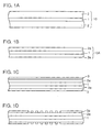
- Figs. 1A to 1D are sectional views schematically showing steps of a first method of forming a refractive index distribution in an optical fiber member;
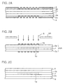
- Figs. 2A to 2C are sectional views schematically showing steps following that of Fig. 1D;
- Figs. 3A to 3D are sectional views schematically showing a second method of forming a refractive index distribution in an optical fiber member;
- Figs. 4A to 4C schematically illustrate a conventional method of forming a refractive index distribution in an optical fiber member through an interference fringe caused by a laser beam; and
- Fig. 5 schematically illustrates a conventional method of forming a refractive index distribution in an optical fiber member through a slit.
DESCRIPTION OF THE PREFERRED EMBODIMENTS
-
Figs. 1A to 1D and 2A to 2C are sectional views schematically illustrating a first method of forming a refractive index distribution in a light transmission path. The light transmission path includes an optical fiber member or a plane waveguide path which is generally applied to optical communication, while the application thereof is not necessarily restricted to this. In short, the light transmission path may include a core part having a high refractive index and a clad part of a surface layer having a lower refractive index than the core part.
-
Fig. 1A shows an exemplary section along the longitudinal direction of an ordinary single mode optical fiber member. This optical fiber member 10 includes a core 1 and a clad layer 2 covering the core 1. In general, the core 1 has a sectional diameter of 10 µm, and the clad layer 2 has that of 7.5 µm. Namely, the optical fiber member 10 has an outer diameter of 125 µm.
-
Referring to Fig. 1B, the clad layer 2 is worked into a clad layer 2a of not more than 50 µm in thickness with aqueous hydrofluoric acid. This process is desirable for improving the efficiency of reaction between an electromagnetic wave which is applied later and the core 1. When a strong electromagnetic wave is employed, therefore, the clad layer 2 may not necessarily be reduced in thickness.
-
While the clad layer 2a is preferably reduced in thickness in order to improve the reaction efficiency between the applied electromagnetic wave and the core 1, the light transmission loss of the optical fiber member 10 is increased if the clad layer 2a is extremely reduced in thickness. Therefore, the clad layer 2a preferably has a thickness of at least 10 µm. In concrete Example, an optical fiber member 10 having an outer diameter of 125 µm was dipped in 50 % aqueous hydrofluoric acid for 20 minutes, and worked into an optical fiber member 10A of 50 µm in outer diameter. Namely, the clad layer 2a of the optical fiber member 10A has a thickness of 20 µm.
-
Referring to Fig. 1C, a photosensitive material layer 3 is applied onto the surface of the clad layer 2a which is reduced in thickness. The material for the photosensitive material layer 3 can be selected from various materials, such as PMMA (polymethyl methacrylate) which is photosensitive resin, for example. In concrete Example, PMMA was applied in a thickness of 1 µm, dried and thereafter heated in the air to 170 DEG C and maintained in this state for 30 minutes, in order to form the photosensitive material layer 3.
-
Referring to Fig. 1D, the PMMA layer 3 is worked into a resin mask pattern 3a including a groove pattern having a period of 0.5 µm through well-known photolithography. A refractive index distribution can be formed in the core 1 by transversely irradiating the optical fiber member 10A with an electromagnetic wave through the resin mask pattern 3 a. In consideration of shielding performance with respect to the electromagnetic wave, however, the resin mask pattern 3 a is preferably replaced with a metal mask pattern, as described below.
-
Referring to Fig. 2A, at least the clad layer surface which is exposed from the resin mask pattern 3a is covered with a metal layer 4. The metal layer 4 can be made of W, Ta or the like. In concrete Example, a thin film of W having a thickness of 0.3 µm was formed by vacuum deposition. In this case, the resin mask pattern 3a is also covered with the W thin film 4.
-
Referring to Fig. 2B, the resin mask pattern 3a is removed, whereby the portion of the W thin film 4 covering the resin mask pattern 3a is removed by a lift-off method, while leaving a metal mask pattern 4a. In this state, the optical fiber member 10A is transversely irradiated with an electromagnetic wave through a slit 5A as shown by arrows 5, whereby a refractive index fluctuation distribution 1a corresponding to the metal mask pattern 4a is formed in the core 1. In this case, the core 1 is directly irradiated with the electromagnetic wave through the metal mask pattern 4a with no necessity for forming an interference or diffraction fringe of the electromagnetic wave, and hence the electromagnetic wave can be prepared from not only visible light or ultraviolet radiation, but an X-ray having high efficiency of causing refractive index change.In concrete Example, the refractive index for light of a specific wavelength by the formed permanent refractive index distribution 1a was increased with increase of the irradiation time, to form a narrow-band reflection filter in about 30 seconds when core 1 was irradiated with an X-ray through the W mask pattern 4a of 0.3 µm.
-
Finally with reference to Fig. 2C, the clad layer 2a is preferably covered with a flexible reinforcing resin layer 6. This flexible resin layer 6 is adapted to reinforce the mechanical strength of the thinned optical fiber member 10A, and can be formed by applying ultraviolet setting resin and hardening the same by irradiation with ultraviolet radiation from an UV lamp or the like, for example. While the reinforcing resin layer 6 is applied after removal of the metal mask pattern 4a in Fig. 2C, the same may alternatively be applied while leaving the metal mask pattern 4a.
-
Figs. 3A to 3D are sectional views schematically illustrating a second method of forming a refractive index distribution in an optical fiber member.
-
Referring to Fig. 3A, a metal layer 8 consisting of W, Ta or the like is deposited on a support film 7 consisting of a carbon film, a silicon nitride film or a silicon carbide film by sputtering, for example.
-
Referring to Fig. 3B, the metal layer 8 is worked into a metal mask pattern 8a including a periodic groove pattern through well-known photolithography, thereby forming a mask film 9.
-
Referring to Fig. 3C, the mask film 9 is so arranged that the metal layer pattern 8a approximates an optical fiber member 10A. The optical fiber member 10A includes a core 1 and a thinned clad layer 2a. In this state, a permanent refractive index fluctuation distribution 1 a corresponding to the metal layer pattern 8a can be formed in the core 1 by irradiating the core 1 with an electromagnetic wave expressed by arrows 5 through a slit 5A and the mask film 9.
-
Finally with reference to Fig. 3D, the thinned clad layer 2a is covered with a flexible reinforcing resin layer 6, preferably similarly to that shown in Fig. 2C.
-
The inventor has first found that extremely larger refractive index change is caused in the core 1 during irradiation with light 5 as shown in Fig. 2B or 3C, as compared with permanent refractive index change remaining in the core 1 after the irradiation with the light 5. For example, it has been recognized that refractive index change which is caused in the core 1 during irradiation with light 5 of high intensity can reach about 10 times a refractive index which can permanently remain in the core 1 after removal of the light 5. It has also been recognized that the refractive index change in the core 1 can be dynamically changed in response to the light intensity by changing the intensity of the light 5 during the irradiation therewith.
-
Namely, a light transmission path comprising a periodic fringy shielding pattern on its surface as shown in Fig. 2B or Fig. 3C can be employed as an optical filter whose control transmission characteristics can be dynamically controlled.
-
As concrete Example of such an optical filter, a periodic tungsten shielding pattern 4a at a pitch of 0.5 µm was formed by X-ray lithography through steps similar to those shown in Figs. 1A to 1C and 2A and 2B. The optical filter shown in Fig. 2B having such a shielding pattern 4a was irradiated with a semiconductor laser beam 5 having a wavelength of 0.65 µm. During the irradiation with the laser beam 5, the transmission attenuation factor of the optical filter was controllable by adjusting the intensity of the laser beam 5, while the bandwidth of the transmitted light was controllable in the range of 0.5 nm to 60 nm by adjusting the slit 5A shown in Fig. 2B and changing the length of the region irradiated with the laser beam 5. Further, it was possible to control the central wavelength of the transmitted light in the range of 1.2 µm to 1.7 µm by applying mechanical force to the optical filter.
-
According to the present invention, as hereinabove described, it is possible not only to provide a method which can form static and dynamic refractive index distributions in a light transmission path with excellent controllability in a short time, but to provide an optical filter whose transmission characteristics can be dynamically controlled and a method of using the same.