EP1672327A2 - Angle measuring device - Google Patents
Angle measuring device Download PDFInfo
- Publication number
- EP1672327A2 EP1672327A2 EP05020999A EP05020999A EP1672327A2 EP 1672327 A2 EP1672327 A2 EP 1672327A2 EP 05020999 A EP05020999 A EP 05020999A EP 05020999 A EP05020999 A EP 05020999A EP 1672327 A2 EP1672327 A2 EP 1672327A2
- Authority
- EP
- European Patent Office
- Prior art keywords
- measuring device
- angle measuring
- cap
- circuit board
- printed circuit
- Prior art date
- Legal status (The legal status is an assumption and is not a legal conclusion. Google has not performed a legal analysis and makes no representation as to the accuracy of the status listed.)
- Granted
Links
- 230000008878 coupling Effects 0.000 claims abstract description 11
- 238000010168 coupling process Methods 0.000 claims abstract description 11
- 238000005859 coupling reaction Methods 0.000 claims abstract description 11
- 125000006850 spacer group Chemical group 0.000 claims description 8
- 239000002184 metal Substances 0.000 description 5
- 239000004020 conductor Substances 0.000 description 2
- 230000003321 amplification Effects 0.000 description 1
- 238000005266 casting Methods 0.000 description 1
- 150000001875 compounds Chemical class 0.000 description 1
- 230000001419 dependent effect Effects 0.000 description 1
- 238000009434 installation Methods 0.000 description 1
- 238000005259 measurement Methods 0.000 description 1
- 238000003199 nucleic acid amplification method Methods 0.000 description 1
- 238000007493 shaping process Methods 0.000 description 1
Images


Classifications
-
- G—PHYSICS
- G01—MEASURING; TESTING
- G01D—MEASURING NOT SPECIALLY ADAPTED FOR A SPECIFIC VARIABLE; ARRANGEMENTS FOR MEASURING TWO OR MORE VARIABLES NOT COVERED IN A SINGLE OTHER SUBCLASS; TARIFF METERING APPARATUS; MEASURING OR TESTING NOT OTHERWISE PROVIDED FOR
- G01D5/00—Mechanical means for transferring the output of a sensing member; Means for converting the output of a sensing member to another variable where the form or nature of the sensing member does not constrain the means for converting; Transducers not specially adapted for a specific variable
- G01D5/26—Mechanical means for transferring the output of a sensing member; Means for converting the output of a sensing member to another variable where the form or nature of the sensing member does not constrain the means for converting; Transducers not specially adapted for a specific variable characterised by optical transfer means, i.e. using infrared, visible, or ultraviolet light
- G01D5/32—Mechanical means for transferring the output of a sensing member; Means for converting the output of a sensing member to another variable where the form or nature of the sensing member does not constrain the means for converting; Transducers not specially adapted for a specific variable characterised by optical transfer means, i.e. using infrared, visible, or ultraviolet light with attenuation or whole or partial obturation of beams of light
- G01D5/34—Mechanical means for transferring the output of a sensing member; Means for converting the output of a sensing member to another variable where the form or nature of the sensing member does not constrain the means for converting; Transducers not specially adapted for a specific variable characterised by optical transfer means, i.e. using infrared, visible, or ultraviolet light with attenuation or whole or partial obturation of beams of light the beams of light being detected by photocells
- G01D5/347—Mechanical means for transferring the output of a sensing member; Means for converting the output of a sensing member to another variable where the form or nature of the sensing member does not constrain the means for converting; Transducers not specially adapted for a specific variable characterised by optical transfer means, i.e. using infrared, visible, or ultraviolet light with attenuation or whole or partial obturation of beams of light the beams of light being detected by photocells using displacement encoding scales
- G01D5/3473—Circular or rotary encoders
- G01D5/34738—Axles; Driving or coupling means
-
- G—PHYSICS
- G01—MEASURING; TESTING
- G01D—MEASURING NOT SPECIALLY ADAPTED FOR A SPECIFIC VARIABLE; ARRANGEMENTS FOR MEASURING TWO OR MORE VARIABLES NOT COVERED IN A SINGLE OTHER SUBCLASS; TARIFF METERING APPARATUS; MEASURING OR TESTING NOT OTHERWISE PROVIDED FOR
- G01D11/00—Component parts of measuring arrangements not specially adapted for a specific variable
- G01D11/24—Housings ; Casings for instruments
- G01D11/245—Housings for sensors
Definitions
- the invention relates to an angle measuring device according to claim 1.
- Angular measuring devices often also called rotary encoders, are used to measure rotational movements of a rotatably mounted body, in particular a shaft, over one or more revolutions (multiturn mode of operation). The rotational movement is detected incrementally or absolutely. In conjunction with gear racks and gears or with threaded spindles, linear movements can also be measured with an angle measuring device.
- connecting cable of the angle measuring device is supplied to an operating voltage and the measuring signals removed and forwarded to a subsequent electronics.
- an opening is provided on a cap of the angle-measuring device, through which the connection cable of the angle-measuring device can be fed and contacted there with a suitable electrical connection unit.
- the invention has for its object to provide an angle measuring device of the type mentioned above, which allows a simple and reliable means of rapid assembly, wherein the angle measuring device can be sealed well against the environment and an electrical coupling to the angle measuring device works reliably.
- At least one spacer is provided to optimize the ease and function of an electrical coupling and to improve the tightness of the angle measuring device, with the aid of which the cap is positioned relative to the circuit board such that the opening is aligned with respect to the electrical coupling element.
- the angle measuring device has means by which, in the end, a correlation between the cap and an electrical coupling element that is unambiguous with respect to the angular position is ensured.
- the aforementioned means is, for example, a positive connection between a base body of the angle measuring device and the cap
- dowel pins may be attached directly to the cap (or be part of the cap), which require an angle-faithful assembly with corresponding holes in the circuit board.
- the cap has elements which cooperate with the circuit board such that a relative angular position between the cap and the circuit board can be fixed by a positive connection.
- angle gauges are part of a data network, e.g. with an Ethernet architecture, to which they supply measurement data but also receive data from it.
- network connectors or network sockets are used as electrical coupling elements in this connection, for example so-called RJ45 connectors or corresponding sockets.
- the angle measuring device comprises at least one additional contact element for producing a electrical connection with one or more signal lines.
- the contact element is configured in such a way that the angle measuring device as a whole can be attached to the same function in at least two different installation positions.
- the corresponding contact elements may be designed as ring contacts.
- the contact elements can be designed as sheet metal parts.
- the contact elements can also be defined by printed conductors or pads on a printed circuit board, which is located in the end region of the angle measuring device.
- the end of the external signal line which cooperates with the contact element designed as a resilient component to allow a reliable electrical contact.
- the angle measuring device shown in FIGS. 1 to 5 has a shaft 7 for connection to a body to be measured.
- the angle measuring device itself is attached via a cap 1 to another body by means of flange holes 1.4.
- the body to be measured is for example a motor shaft and the other body is a stationary motor housing.
- Angle measuring devices designed for these applications are also often referred to as rotary encoders.
- the angle measuring device is constructed so that its cap 1 forms a part of the outer contour of the motor after attachment to a motor housing. In other words, the angle measuring device is not surrounded by a further housing part, but forms after assembly with the outer contour of the motor.
- the angle measuring device comprises a main body 3, which has a recess 3.1, in which an annular electrically non-conductive insulating body 4 is inserted.
- this insulating body are a first ring contact 4.1 and a second ring contact 4.2, which consist of an electrically conductive material.
- the ring contacts 4.1, 4.2 are arranged concentrically with respect to the shaft 7.
- the shaft 7 is rotatably supported in the base body 3 by means of bearings 6, wherein on the shaft 7 arranged in the interior of the angle measuring code disc 8 is fixed and the shaft 7 via a gear 5 drives one or more further code discs.
- a gear 5 drives one or more further code discs.
- the code disk 8 is scanned in the example shown photoelectrically by a scanning device.
- Corresponding photosensitive detectors are located on a printed circuit board 2, on which inter alia, electrical components for signal shaping - for example, for amplification and digitization - of the signals supplied by the detectors are arranged.
- On the circuit board is next to this measuring electronics continue an electrical coupling element, in the illustrated embodiment, a socket 2.1 through which in the presented embodiment a RJ45 connector can be included.
- the socket 2.1 is accurately positioned on the circuit board 2.
- the cup-shaped cap 1 is provided, which is clamped over the circumference on the base body 3.
- this compound is a press connection.
- the base body has a fitting recess 3.2.
- the cap 1 is aligned so that a nose 1.3 is received by the fitting recess 3.2 (Fig. 4).
- the cap 1 has as integral components three spacers 1.1 and an opening 1.2.
- the cap 1 is designed in the presented embodiment as a casting, wherein the end faces were machined to increase the dimensional accuracy of the length of the spacer 1.1. In this way, an extremely accurate position of the end faces of the spacers 1.1 with respect to the opening 1.2 is achieved.
- a corresponding plug can be inserted into the socket 2.1.
- the wall of the opening 1.2 serves as a guide for the plug.
- Such angle measuring devices or rotary encoders are often used in comparatively rough industrial environments, which is why it is important that the cap 1 encloses the interior of the angle measuring device tight.
- the area of the plug connection or the opening 1.2 and the socket 2.1 is critical in this context. A high degree of tightness in this area can not be achieved if the position of the bush 2.1 relative to the opening 1.2 in the cap 1 has too great a tolerance.
- the socket 2.1 is accurately placed on the printed circuit board 2, but the printed circuit board 2 itself has tolerances with respect to its flatness and thickness. These tolerances are comparatively large. Therefore, in conventional designs, the plug would generally be biased relative to the socket 2.1 by the opening 1.2 acting as the guide be positioned. This cant can be so large that the connector is not produced, or produces electrically unreliable contacts. In addition, if a connector is still produced, stomata in the region of the connector arise, resulting in leaks.
- the base body 3 is structurally designed so that the circuit board 2 can be mounted only in a certain angular position (with respect to the axis of the shaft 7) in the angle measuring device.
- the passport recess 3.2 and the nose 1.3 as already mentioned, a relation between the cap 1 and the main body 3, which is unique with regard to the angular position, is ensured.
- a snug fit the plug to the socket 2.1 is achieved in the tangential direction.
- angle measuring devices or encoders are not only connected to the environment by the plug connection for which the socket 2.1 is provided.
- the angle measuring devices are supplied by separate, coming from the outside, signal lines signals. These signals can originate, for example, from a temperature sensor of the motor, to which the angle measuring device or the cap 1 is flanged.
- two encircling ring contacts 4.1, 4.2 are arranged on the underside of the angle measuring device. These serve to cooperate with (not shown in the figures) resilient contact elements of a temperature output of the engine.
- the angle measuring device is designed in this way, that they can be flange-mounted on the motor housing in different angular positions, depending on the required cable outlet direction, and that nevertheless a contacting of the signal outputs of the motor is possible.
- the contact elements of the temperature output of the motor always meet the ring contacts 4.1, 4.2 of the angle measuring device, regardless of the angle position in which the angle measuring device was flanged to the engine.
- the ring contacts 4.1, 4.2 are each designed as one-piece sheet metal parts, which are provided with a gold-plated layer. Aligned axially parallel to the shaft 7 are metal strips 4.11, 4.12, which are each a part of the ring contacts 4.1, 4.2.
- the insulating body 4 is configured so that it has a region 4.1, which is aligned axially parallel to the shaft 7 within the base body 3 and the metal strip 4.11, 4.12 receives.
- the metal strips 4.11, 4.12 terminate at the circuit board 2 and are contacted there to corresponding tracks.
- the temperature signals are then further processed in corresponding circuits on the printed circuit board 2 and output via the socket 2.1 as digital values and possibly also as analog signals.
Abstract
Description
Die Erfindung betrifft eine Winkelmesseinrichtung gemäß dem Patentanspruch 1.The invention relates to an angle measuring device according to
Winkelmesseinrichtungen, häufig auch Drehgeber genannt, dienen zur Messung von Drehbewegungen eines drehbar gelagerten Körpers, insbesondere einer Welle, über eine oder mehrere Umdrehungen (Multiturn-Funktionsweise). Die Drehbewegung wird dabei inkremental oder absolut erfasst. In Verbindung mit Zahnstangen und Zahnrädern oder mit Gewindespindeln lassen sich mit einer Winkelmesseinrichtung auch lineare Bewegungen messen.Angular measuring devices, often also called rotary encoders, are used to measure rotational movements of a rotatably mounted body, in particular a shaft, over one or more revolutions (multiturn mode of operation). The rotational movement is detected incrementally or absolutely. In conjunction with gear racks and gears or with threaded spindles, linear movements can also be measured with an angle measuring device.
Über Anschlusskabel werden der Winkelmesseinrichtung eine Betriebsspannung zugeführt und die Messsignale abgenommen und an eine Folgeelektronik weitergeleitet. Hierzu ist bei bekannten Winkelmesseinrichtungen an einer Kappe der Winkelmesseinrichtung eine Öffnung vorgesehen, durch die hindurch das Anschlusskabel der Winkelmesseinrichtung zugeführt und dort mit einer geeigneten elektrischen Anschlusseinheit kontaktiert werden kann.About connecting cable of the angle measuring device is supplied to an operating voltage and the measuring signals removed and forwarded to a subsequent electronics. For this purpose, in the case of known angle-measuring devices, an opening is provided on a cap of the angle-measuring device, through which the connection cable of the angle-measuring device can be fed and contacted there with a suitable electrical connection unit.
Der Erfindung liegt die Aufgabe zugrunde, eine Winkelmesseinrichtung der eingangs genannten Art zu schaffen, die mit einfachen Mitteln eine zuverlässige und schnelle Montage ermöglicht, wobei die Winkelmesseinrichtung gegenüber der Umgebung gut abgedichtet werden kann und eine elektrische Kupplung an der Winkelmesseinrichtung zuverlässig arbeitet.The invention has for its object to provide an angle measuring device of the type mentioned above, which allows a simple and reliable means of rapid assembly, wherein the angle measuring device can be sealed well against the environment and an electrical coupling to the angle measuring device works reliably.
Diese Aufgabe wird erfindungsgemäß durch die Schaffung einer Winkelmesseinrichtung mit den Merkmalen des Patentanspruchs 1 gelöst.This object is achieved by the provision of an angle measuring device with the features of
Demnach ist zur Optimierung der Leichtgängigkeit und Funktion einer elektrischen Kupplung sowie zur Verbesserung der Dichtheit der Winkelmesseinrichtung zumindest ein Abstandshalter vorgesehen, mit dessen Hilfe die Kappe relativ zur Leiterplatte derart positioniert ist, dass die Öffnung bezüglich des elektrischen Kupplungselements ausgerichtet ist. Durch diese exakte relative räumliche Zuordnung der Kappe gegenüber der Leiterplatte kann ein hoher Grad an Dichtheit im Bereich der elektrischen Kupplung reproduzierbar erreicht werden.Accordingly, at least one spacer is provided to optimize the ease and function of an electrical coupling and to improve the tightness of the angle measuring device, with the aid of which the cap is positioned relative to the circuit board such that the opening is aligned with respect to the electrical coupling element. By this exact relative spatial allocation of the cap relative to the circuit board, a high degree of tightness in the field of electrical coupling can be reproducibly achieved.
Ferner weist die Winkelmesseinrichtung Mittel auf durch die letztlich eine bezüglich der Winkellage eindeutige Zuordnung zwischen der Kappe und eines elektrischen Kupplungselements sichergestellt ist. Das vorgenannte Mittel ist beispielsweise eine formschlüssige Verbindung zwischen einem Grundkörper der Winkelmesseinrichtung und der Kappe Alternativ dazu können auch Passstifte direkt an der Kappe angebracht sein (oder Bestandteil der Kappe sein), die mit entsprechenden Bohrungen in der Leiterplatte eine winkeltreue Montage bedingen. Hier weist also die Kappe Elemente auf, welche mit der Leiterplatte derart zusammenwirken, dass eine relative Winkellage zwischen Kappe und der Leiterplatte durch einen Formschluss festlegbar ist.Furthermore, the angle measuring device has means by which, in the end, a correlation between the cap and an electrical coupling element that is unambiguous with respect to the angular position is ensured. The aforementioned means is, for example, a positive connection between a base body of the angle measuring device and the cap Alternatively, also dowel pins may be attached directly to the cap (or be part of the cap), which require an angle-faithful assembly with corresponding holes in the circuit board. Here, therefore, the cap has elements which cooperate with the circuit board such that a relative angular position between the cap and the circuit board can be fixed by a positive connection.
Häufig sind derartige Winkelmesseinrichtung Bestandteil eines Datennetzwerkes, z.B. mit einer Ethernet-Architektur, an das sie Messdaten liefern aber auch von diesem Daten empfangen. Deshalb werden in diesem Zusammenhang als elektrische Kupplungselemente oft bekannte Netzwerkstecker bzw. Netzwerkbuchsen verwendet, beispielsweise so genannte RJ45-Stecker bzw. entsprechende Buchsen.Often such angle gauges are part of a data network, e.g. with an Ethernet architecture, to which they supply measurement data but also receive data from it. For this reason, often known network connectors or network sockets are used as electrical coupling elements in this connection, for example so-called RJ45 connectors or corresponding sockets.
Gemäß einem weiteren Aspekt der Erfindung umfasst die Winkelmesseinrichtung zumindest ein zusätzliches Kontaktelement zur Herstellung einer elektrischen Verbindung mit einer oder mehreren Signalleitungen. Das Kontaktelement ist derart ausgestaltet, dass die Winkelmesseinrichtung als Ganzes in zumindest zwei unterschiedlichen Einbaulagen funktionsgleich anbaubar ist. Zu diesem Zweck können die entsprechenden Kontaktelemente als Ringkontakte ausgeführt sein. Gemäß einer vorteilhaften Variante können weiterhin die Kontaktelemente als Blechteile ausgestaltet sein. Alternativ dazu können die Kontaktelemente auch durch Leiterbahnen oder Pads auf einer Leiterplatte, die sich im Endbereich der Winkelmesseinrichtung befindet, definiert werden.According to a further aspect of the invention, the angle measuring device comprises at least one additional contact element for producing a electrical connection with one or more signal lines. The contact element is configured in such a way that the angle measuring device as a whole can be attached to the same function in at least two different installation positions. For this purpose, the corresponding contact elements may be designed as ring contacts. According to an advantageous variant, furthermore, the contact elements can be designed as sheet metal parts. Alternatively, the contact elements can also be defined by printed conductors or pads on a printed circuit board, which is located in the end region of the angle measuring device.
Mit Vorteil ist das Ende der externen Signalleitung, welches mit dem Kontaktelement zusammenwirkt als federndes Bauteil ausgestaltet, um eine zuverlässige elektrische Kontaktierung zu ermöglichen.Advantageously, the end of the external signal line, which cooperates with the contact element designed as a resilient component to allow a reliable electrical contact.
Zusätzliche vorteilhafte Ausgestaltungen der Erfindung sind den abhängigen Ansprüchen zu entnehmen.Additional advantageous embodiments of the invention can be found in the dependent claims.
Weitere Merkmale und Vorteile der Erfindung werden bei der nachfolgenden Beschreibung eines Ausführungsbeispiels anhand der Figuren deutlich werden.Further features and advantages of the invention will become apparent in the following description of an embodiment with reference to the figures.
Es zeigen:
Figur 1- eine perspektivische Schnitt-Ansicht einer Winkelmesseinrichtung,
Figur 2- eine perspektivische Ansicht der Winkelmesseinrichtung,
Figur 3- eine perspektivische Ansicht der Winkelmesseinrichtung, mit aufgeschnittener Kappe,
Figur 4- eine weitere perspektivische Schnitt-Ansicht der Winkelmesseinrichtung,
Figur 5- eine weitere perspektivische Ansicht der Winkelmesseinrichtung mit aufgeschnittener Kappe.
- FIG. 1
- a perspective sectional view of an angle measuring device,
- FIG. 2
- a perspective view of the angle measuring device,
- FIG. 3
- a perspective view of the angle measuring device, with cut-cap,
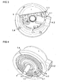
- FIG. 4
- another perspective sectional view of the angle measuring device,
- FIG. 5
- another perspective view of the angle measuring device with cut cap.
Die in den Figuren 1 bis 5 dargestellte Winkelmesseinrichtung weist eine Welle 7 zum Anschluss an einen zu messenden Körper auf. Die Winkelmesseinrichtung selbst wird über eine Kappe 1 an einem weiteren Körper mit Hilfe von Flanschbohrungen 1.4 befestigt. Der zu messende Körper ist beispielsweise eine Motorwelle und der weitere Körper ein stationäres Motorgehäuse. Winkelmesseinrichtungen, die für diese Anwendungen konzipiert sind werden auch häufig als Drehgeber bezeichnet. Im gezeigten Ausführungsbeispiel ist die Winkelmesseinrichtung so konstruiert, dass deren Kappe 1 nach dem Anbau an ein Motorgehäuse einen Teil der Außenkontur des Motors bildet. Mit anderen Worten wird die Winkelmesseinrichtung nicht von einem weiteren Gehäuseteil umgeben, sondern bildet nach erfolgter Montage mit die äußere Kontur des Motors.The angle measuring device shown in FIGS. 1 to 5 has a
Die Winkelmesseinrichtung umfasst einen Grundkörper 3, welcher eine Ausnehmung 3.1 aufweist, in der ein ringförmiger elektrisch nicht-leitender Isolierkörper 4 eingelegt ist. In diesem Isolierkörper befinden sich ein erster Ringkontakt 4.1 und ein zweiter Ringkontakt 4.2, welche aus einem elektrisch leitfähigen Material bestehen. Die Ringkontakte 4.1, 4.2 sind bezüglich der Welle 7 konzentrisch angeordnet.The angle measuring device comprises a
In bekannter Weise ist die Welle 7 im Grundkörper 3 mit Hilfe von Lagern 6 drehbar gelagert, wobei an der Welle 7 eine im Inneren der Winkelmesseinrichtung angeordneten Codescheibe 8 befestigt ist und die Welle 7 über ein Getriebe 5 eine oder mehrere weitere Codescheiben antreibt. Durch das Getriebe 5 und die weiteren Codescheiben wird eine Multitum-Funktionsweise der Winkelmesseinrichtung erreicht.In known manner, the
Die Codescheibe 8 wird im gezeigten Beispiel lichtelektrisch von einer Abtasteinrichtung abgetastet. Entsprechende lichtempfindliche Detektoren befinden sich auf einer Leiterplatte 2, auf der unter anderem elektrische Bauelemente zur Signalformung - beispielsweise zur Verstärkung und Digitalisierung - der von den Detektoren gelieferten Abtastsignalen angeordnet sind. Auf der Leiterplatte befindet sich neben dieser Messelektronik weiterhin ein elektrisches Kupplungselement, im vorgestellten Ausführungsbeispiel eine Buchse 2.1 durch welche im vorgestellten Ausführungsbeispiel ein RJ45 Stecker aufgenommen werden kann. Die Buchse 2.1 ist passgenau auf der Leiterplatte 2 positioniert.The code disk 8 is scanned in the example shown photoelectrically by a scanning device. Corresponding photosensitive detectors are located on a printed
Zum Schutz der Winkelmesseinrichtung und ihrer Messelektronik ist die topfförmige Kappe 1 vorgesehen, welche über den Umfang klemmend am Grundkörper 3 befestigt ist. Im dargestellten Beispiel ist diese Verbindung eine Pressverbindung. Damit eine bezüglich der Winkellage eindeutige Zuordnung zwischen der Kappe 1 und dem Grundkörper 3 sichergestellt ist, weist der Grundkörper eine Pass-Ausnehmung 3.2 auf. Beim Zusammenbau wird die Kappe 1 so ausgerichtet, dass eine Nase 1.3 von der Pass-Ausnehmung 3.2 aufgenommen wird (Fig. 4). Ferner weist die Kappe 1 als integrale Bestandteile drei Abstandshalter 1.1 sowie eine Öffnung 1.2 auf. Die Kappe 1 ist im vorgestellten Ausführungsbeispiel als ein Gussteil ausgestaltet, wobei zur Erhöhung der Maßgenauigkeit der Länge der Abstandshalter 1.1 deren Endflächen spanabhebend bearbeitet wurden. Auf diese Weise wird eine überaus genaue Lage der Endflächen der Abstandshalter 1.1 in Bezug auf die Öffnung 1.2 erreicht.To protect the angle measuring device and its measuring electronics, the cup-
Durch die Öffnung 1.2 kann ein entsprechender Stecker in die Buchse 2.1 eingeschoben werden. Die Wandung der Öffnung 1.2 dient gleichzeitig als Führung für den Stecker.Through the opening 1.2 a corresponding plug can be inserted into the socket 2.1. The wall of the opening 1.2 serves as a guide for the plug.
Derartige Winkelmesseinrichtungen bzw. Drehgeber werden häufig in vergleichsweise rauen Industrieumgebungen eingesetzt, weshalb es wichtig ist, dass die Kappe 1 den Innenraum der Winkelmesseinrichtung dicht umschließt. Gerade der Bereich der Steckverbindung bzw. der Öffnung 1.2 und der Buchse 2.1 ist in diesem Zusammenhang kritisch. Ein hoher Grad an Dichtheit in diesem Bereich ist nicht zu erreichen, wenn die Lage der Buchse 2.1 relativ zur Öffnung 1.2 in der Kappe 1 zu große Toleranzen aufweist.Such angle measuring devices or rotary encoders are often used in comparatively rough industrial environments, which is why it is important that the
Wie bereits erwähnt, wird die Buchse 2.1 passgenau auf der Leiterplatte 2 platziert, jedoch weist die Leiterplatte 2 selbst bezüglich ihrer Ebenheit und Dicke Toleranzen auf. Diese Toleranzen sind vergleichsweise groß. Deshalb würde bei herkömmlichen Bauarten durch die als Führung dienende Öffnung 1.2 der Stecker im Allgemeinen schräg bzw. verkantet relativ zur Buchse 2.1 positioniert werden. Diese Verkantung kann so groß sein, dass die Steckverbindung nicht herstellbar ist, oder elektrisch unzuverlässige Kontakte erzeugt. Darüber hinaus können, wenn eine Steckverbindung noch herstellbar ist, Spaltöffnungen im Bereich der Steckverbindung entstehen, welche in Undichtigkeiten resultieren.As already mentioned, the socket 2.1 is accurately placed on the printed
Eine exakte räumliche Zuordnung zwischen der Buchse 2.1 und der Öffnung 1.2 wird nunmehr dadurch erreicht, dass die Abstandshalter 1.1 sich auf der Leiterplatte 2 abstützen. Die Leiterplatte 2 ruht ihrerseits auf einem Leiterplattenauflager, das im gezeigten Ausführungsbeispiel als ein umlaufender. Absatz 3.3 im Grundkörper 3 ausgebildet ist. Auf diese Weise werden die Dickentoleranzen der Leiterplatte 2 ausgeglichen, so dass in Richtung der Achse der Welle 7 die Öffnung 1.2 exakt in der richtigen Position bezüglich der Buchse 1.2 platziert ist.An exact spatial association between the socket 2.1 and the opening 1.2 is now achieved in that the spacers 1.1 are supported on the
Darüber hinaus ist der Grundkörper 3 konstruktiv so ausgestaltet, dass die Leiterplatte 2 nur in einer bestimmten Winkellage (bezüglich der Achse der Welle 7) in der Winkelmesseinrichtung montiert werden kann. Hinzu kommt, dass durch die Pass-Ausnehmung 3.2 und die Nase 1.3, wie bereits erwähnt, eine bezüglich der Winkellage eindeutige Zuordnung zwischen der Kappe 1 und dem Grundkörper 3 sichergestellt. Somit wird auch in tangentialer Richtung ein passgenauer Anbau des Steckers an der Buchse 2.1 erreicht.In addition, the
Häufig sind aber derartige Winkelmesseinrichtungen bzw. Drehgeber nicht nur durch die Steckverbindung, für welche die Buchse 2.1 vorgesehen ist, mit der Umgebung verbunden. Darüber hinaus werden nämlich oft auch den Winkelmesseinrichtungen durch separate, von außen kommende, Signalleitungen Signale zugeführt. Diese Signale können beispielsweise von einem Temperaturfühler des Motors stammen, an dem die Winkelmesseinrichtung bzw. die Kappe 1 angeflanscht ist. Gemäß den Figuren 4 und 5 sind an der Unterseite der Winkelmesseinrichtung zwei umlaufende Ringkontakte 4.1, 4.2 angeordnet. Diese dienen dazu mit (in den Figuren nicht dargestellten) federnden Kontaktelementen eines Temperaturausgangs des Motors zusammenzuwirken. Die Winkelmesseinrichtung ist dabei so ausgestaltet, dass sie in unterschiedlichen Winkellagen - je nach erforderlicher Kabelabgangsrichtung - am Motorgehäuse angeflanscht werden kann, und dabei aber trotzdem eine Kontaktierung der Signalausgänge des Motors möglich ist. Mit anderen Worten treffen die Kontaktelemente des Temperaturausgangs des Motors stets auf die Ringkontakte 4.1, 4.2 der Winkelmesseinrichtung, unabhängig davon in welcher Winkellage die Winkelmesseinrichtung am Motor angeflanscht wurde.Frequently, however, such angle measuring devices or encoders are not only connected to the environment by the plug connection for which the socket 2.1 is provided. In addition, often also the angle measuring devices are supplied by separate, coming from the outside, signal lines signals. These signals can originate, for example, from a temperature sensor of the motor, to which the angle measuring device or the
Die Ringkontakte 4.1, 4.2 sind jeweils als einstückige Blechteile ausgestaltet, die mit einer vergoldeten Schicht versehen sind. Achsparallel zur Welle 7 ausgerichtet sind Blechstreifen 4.11, 4.12, welche jeweils ein Bestandteil der Ringkontakte 4.1, 4.2 sind. Der Isolierkörper 4 ist so ausgestaltet, das dieser einen Bereich 4.1 aufweist, welcher innerhalb des Grundkörpers 3 achsparallel zur Welle 7 ausgerichtet ist und die Blechstreifen 4.11, 4.12 aufnimmt. Die Blechstreifen 4.11, 4.12 enden an der Leiterplatte 2 und sind dort an entsprechenden Leiterbahnen kontaktiert. Die Temperatursignale werden dann in entsprechenden Schaltungen auf der Leiterplatte 2 weiterverarbeitet und über die Buchse 2.1 als digitale Werte ggf. auch als analoge Signale ausgegeben.The ring contacts 4.1, 4.2 are each designed as one-piece sheet metal parts, which are provided with a gold-plated layer. Aligned axially parallel to the
Claims (6)
Applications Claiming Priority (1)
| Application Number | Priority Date | Filing Date | Title |
|---|---|---|---|
| DE102004060864A DE102004060864A1 (en) | 2004-12-17 | 2004-12-17 | Angle measuring device |
Publications (3)
| Publication Number | Publication Date |
|---|---|
| EP1672327A2 true EP1672327A2 (en) | 2006-06-21 |
| EP1672327A3 EP1672327A3 (en) | 2011-02-09 |
| EP1672327B1 EP1672327B1 (en) | 2016-01-13 |
Family
ID=36128356
Family Applications (1)
| Application Number | Title | Priority Date | Filing Date |
|---|---|---|---|
| EP05020999.8A Not-in-force EP1672327B1 (en) | 2004-12-17 | 2005-09-27 | Angle measuring device |
Country Status (5)
| Country | Link |
|---|---|
| US (1) | US7446305B2 (en) |
| EP (1) | EP1672327B1 (en) |
| JP (1) | JP4922608B2 (en) |
| CN (1) | CN100487366C (en) |
| DE (1) | DE102004060864A1 (en) |
Cited By (1)
| Publication number | Priority date | Publication date | Assignee | Title |
|---|---|---|---|---|
| EP3581910A1 (en) * | 2018-06-14 | 2019-12-18 | Baumer Electric AG | Rotary encoder for rail vehicles |
Families Citing this family (8)
| Publication number | Priority date | Publication date | Assignee | Title |
|---|---|---|---|---|
| DE502006000758D1 (en) * | 2005-03-16 | 2008-06-26 | Busch Dieter & Co Prueftech | Vibration sensor or transducer |
| DE102006041056C5 (en) * | 2006-09-01 | 2015-02-19 | Siemens Aktiengesellschaft | Encoder for connecting additional sensors and electrical machine with such a rotary encoder |
| DE102008008278A1 (en) * | 2008-02-07 | 2009-08-13 | Dr. Johannes Heidenhain Gmbh | Angle measuring device |
| DE102011005351A1 (en) * | 2011-03-10 | 2012-09-13 | Dr. Johannes Heidenhain Gmbh | Assembly of an angle measuring device and method for producing this unit |
| US8943702B2 (en) * | 2012-04-30 | 2015-02-03 | Caterpillar Inc. | Guard for sensor apparatus in tilting arrangement |
| DE102014205397A1 (en) * | 2014-03-24 | 2015-09-24 | Dr. Johannes Heidenhain Gmbh | Sensing element for an inductive angle measuring device |
| JP6412176B2 (en) | 2017-01-11 | 2018-10-24 | ファナック株式会社 | Electric motor |
| CN113776564A (en) * | 2021-09-29 | 2021-12-10 | 深圳市宽田科技有限公司 | Built-in rotary encoder that detects rotational speed |
Citations (2)
| Publication number | Priority date | Publication date | Assignee | Title |
|---|---|---|---|---|
| EP0776065A1 (en) * | 1995-11-21 | 1997-05-28 | Dr. Johannes Heidenhain GmbH | Angle measuring device |
| US5708496A (en) * | 1996-03-11 | 1998-01-13 | Renco Encoders, Inc. | Modular optical shaft encoder having a slide gap centering mechanism and method of use |
Family Cites Families (6)
| Publication number | Priority date | Publication date | Assignee | Title |
|---|---|---|---|---|
| JPH04115120A (en) * | 1990-09-05 | 1992-04-16 | Alps Electric Co Ltd | Assembling method for magnetic-type rotary encoder |
| DE19641929C2 (en) * | 1996-10-11 | 2000-01-05 | Ruhlatec Industrieprodukte | Encoder |
| US6166374A (en) * | 1998-11-04 | 2000-12-26 | Agilent Technologies, Inc. | Molded spring gap setting mechanism for optical encoders |
| EP1043570A3 (en) * | 1999-04-08 | 2004-06-23 | Alps Electric Co., Ltd. | Rotational angle sensor |
| DE10031302A1 (en) * | 2000-06-27 | 2002-01-10 | Heidenhain Gmbh Dr Johannes | Winkelmeßrichtung |
| US6919558B2 (en) * | 2002-06-10 | 2005-07-19 | Hewlett-Packard Development Company, L.P. | Positioning apparatus and assembly thereof |
-
2004
- 2004-12-17 DE DE102004060864A patent/DE102004060864A1/en not_active Withdrawn
-
2005
- 2005-09-27 EP EP05020999.8A patent/EP1672327B1/en not_active Not-in-force
- 2005-12-13 US US11/301,676 patent/US7446305B2/en not_active Expired - Fee Related
- 2005-12-15 JP JP2005361481A patent/JP4922608B2/en not_active Expired - Fee Related
- 2005-12-16 CN CNB200510131765XA patent/CN100487366C/en not_active Expired - Fee Related
Patent Citations (2)
| Publication number | Priority date | Publication date | Assignee | Title |
|---|---|---|---|---|
| EP0776065A1 (en) * | 1995-11-21 | 1997-05-28 | Dr. Johannes Heidenhain GmbH | Angle measuring device |
| US5708496A (en) * | 1996-03-11 | 1998-01-13 | Renco Encoders, Inc. | Modular optical shaft encoder having a slide gap centering mechanism and method of use |
Cited By (1)
| Publication number | Priority date | Publication date | Assignee | Title |
|---|---|---|---|---|
| EP3581910A1 (en) * | 2018-06-14 | 2019-12-18 | Baumer Electric AG | Rotary encoder for rail vehicles |
Also Published As
| Publication number | Publication date |
|---|---|
| CN1789910A (en) | 2006-06-21 |
| US20060131490A1 (en) | 2006-06-22 |
| JP2006171003A (en) | 2006-06-29 |
| EP1672327A3 (en) | 2011-02-09 |
| JP4922608B2 (en) | 2012-04-25 |
| DE102004060864A1 (en) | 2006-06-22 |
| US7446305B2 (en) | 2008-11-04 |
| EP1672327B1 (en) | 2016-01-13 |
| CN100487366C (en) | 2009-05-13 |
Similar Documents
| Publication | Publication Date | Title |
|---|---|---|
| EP1672327B1 (en) | Angle measuring device | |
| EP1672326B1 (en) | Angle measurement device | |
| EP1464935B1 (en) | Apparatus for determining the torque applied to a shaft | |
| EP1851567A1 (en) | Modular ultrasonic sensor | |
| WO2015044034A2 (en) | Electric machine and connecting unit for an electric machine | |
| EP2824426B1 (en) | Capacitative rotation angle sensor | |
| EP0375622B1 (en) | Measuring array comprising at least one linear electronic length-measuring probe | |
| EP2687823A2 (en) | Device for the recording and processing of sensor measurement values and/or for controlling actuators | |
| EP1924834A1 (en) | Sensor arrangement | |
| EP2326921B1 (en) | Rotary transducer and series of rotary transducers | |
| EP2527809A1 (en) | Sensor device | |
| EP0284787B1 (en) | Displacement and/or position indicator | |
| DE102006036746B4 (en) | Position measuring device | |
| DE102017212039B4 (en) | Rotation angle measuring device | |
| EP2797176A1 (en) | Sensor unit | |
| EP2038619A1 (en) | Sensor arrangement | |
| DE3643164A1 (en) | ENCODER AND METHOD FOR THE PRODUCTION THEREOF | |
| DE102020122368B4 (en) | Position sensor and manufacturing method as well as method for determining a position of a linear actuator | |
| DE102011084411A1 (en) | Angle measurement device i.e. rotary encoder, for measuring relative angle position between e.g. motor shaft and stationary motor housing, has holding element producing force and pushing component toward cap in assembled state | |
| WO2019001614A1 (en) | Bearing sensor ring, sensor bearing arrangement and process for the production thereof | |
| DE102007016536B4 (en) | Device for measuring a pressure prevailing in a pressure medium | |
| DE19543372A1 (en) | Angle measurement device for measuring shaft angle over multiple rotations - has cable strain relieving device inside conducting housing forming integral part of housing and effective irrespective opening lid position, with cable having conducting sleeve in contact with strain relieving device | |
| EP1452836A1 (en) | Angular displacement sensing apparatus | |
| DE19741355A1 (en) | Magnet sensor for locking rotational speed, e.g. of gear=shaped magnet rotor | |
| EP3581910B1 (en) | Rotary encoder for rail vehicles |
Legal Events
| Date | Code | Title | Description |
|---|---|---|---|
| PUAI | Public reference made under article 153(3) epc to a published international application that has entered the european phase |
Free format text: ORIGINAL CODE: 0009012 |
|
| AK | Designated contracting states |
Kind code of ref document: A2 Designated state(s): AT BE BG CH CY CZ DE DK EE ES FI FR GB GR HU IE IS IT LI LT LU LV MC NL PL PT RO SE SI SK TR |
|
| AX | Request for extension of the european patent |
Extension state: AL BA HR MK YU |
|
| PUAL | Search report despatched |
Free format text: ORIGINAL CODE: 0009013 |
|
| AK | Designated contracting states |
Kind code of ref document: A3 Designated state(s): AT BE BG CH CY CZ DE DK EE ES FI FR GB GR HU IE IS IT LI LT LU LV MC NL PL PT RO SE SI SK TR |
|
| AX | Request for extension of the european patent |
Extension state: AL BA HR MK YU |
|
| RIC1 | Information provided on ipc code assigned before grant |
Ipc: G01D 5/347 20060101ALI20110103BHEP Ipc: G01D 11/24 20060101AFI20060418BHEP |
|
| 17P | Request for examination filed |
Effective date: 20110809 |
|
| AKX | Designation fees paid |
Designated state(s): AT BE BG CH CY CZ DE DK EE ES FI FR GB GR HU IE IS IT LI LT LU LV MC NL PL PT RO SE SI SK TR |
|
| GRAP | Despatch of communication of intention to grant a patent |
Free format text: ORIGINAL CODE: EPIDOSNIGR1 |
|
| INTG | Intention to grant announced |
Effective date: 20151009 |
|
| GRAS | Grant fee paid |
Free format text: ORIGINAL CODE: EPIDOSNIGR3 |
|
| GRAA | (expected) grant |
Free format text: ORIGINAL CODE: 0009210 |
|
| AK | Designated contracting states |
Kind code of ref document: B1 Designated state(s): AT BE BG CH CY CZ DE DK EE ES FI FR GB GR HU IE IS IT LI LT LU LV MC NL PL PT RO SE SI SK TR |
|
| REG | Reference to a national code |
Ref country code: GB Ref legal event code: FG4D Free format text: NOT ENGLISH |
|
| REG | Reference to a national code |
Ref country code: CH Ref legal event code: EP |
|
| REG | Reference to a national code |
Ref country code: IE Ref legal event code: FG4D Free format text: LANGUAGE OF EP DOCUMENT: GERMAN |
|
| REG | Reference to a national code |
Ref country code: AT Ref legal event code: REF Ref document number: 770839 Country of ref document: AT Kind code of ref document: T Effective date: 20160215 |
|
| REG | Reference to a national code |
Ref country code: DE Ref legal event code: R096 Ref document number: 502005015079 Country of ref document: DE |
|
| REG | Reference to a national code |
Ref country code: LT Ref legal event code: MG4D |
|
| REG | Reference to a national code |
Ref country code: NL Ref legal event code: MP Effective date: 20160113 |
|
| PG25 | Lapsed in a contracting state [announced via postgrant information from national office to epo] |
Ref country code: NL Free format text: LAPSE BECAUSE OF FAILURE TO SUBMIT A TRANSLATION OF THE DESCRIPTION OR TO PAY THE FEE WITHIN THE PRESCRIBED TIME-LIMIT Effective date: 20160113 |
|
| PG25 | Lapsed in a contracting state [announced via postgrant information from national office to epo] |
Ref country code: GR Free format text: LAPSE BECAUSE OF FAILURE TO SUBMIT A TRANSLATION OF THE DESCRIPTION OR TO PAY THE FEE WITHIN THE PRESCRIBED TIME-LIMIT Effective date: 20160414 Ref country code: IT Free format text: LAPSE BECAUSE OF FAILURE TO SUBMIT A TRANSLATION OF THE DESCRIPTION OR TO PAY THE FEE WITHIN THE PRESCRIBED TIME-LIMIT Effective date: 20160113 Ref country code: ES Free format text: LAPSE BECAUSE OF FAILURE TO SUBMIT A TRANSLATION OF THE DESCRIPTION OR TO PAY THE FEE WITHIN THE PRESCRIBED TIME-LIMIT Effective date: 20160113 Ref country code: FI Free format text: LAPSE BECAUSE OF FAILURE TO SUBMIT A TRANSLATION OF THE DESCRIPTION OR TO PAY THE FEE WITHIN THE PRESCRIBED TIME-LIMIT Effective date: 20160113 |
|
| PG25 | Lapsed in a contracting state [announced via postgrant information from national office to epo] |
Ref country code: LV Free format text: LAPSE BECAUSE OF FAILURE TO SUBMIT A TRANSLATION OF THE DESCRIPTION OR TO PAY THE FEE WITHIN THE PRESCRIBED TIME-LIMIT Effective date: 20160113 Ref country code: LT Free format text: LAPSE BECAUSE OF FAILURE TO SUBMIT A TRANSLATION OF THE DESCRIPTION OR TO PAY THE FEE WITHIN THE PRESCRIBED TIME-LIMIT Effective date: 20160113 Ref country code: PT Free format text: LAPSE BECAUSE OF FAILURE TO SUBMIT A TRANSLATION OF THE DESCRIPTION OR TO PAY THE FEE WITHIN THE PRESCRIBED TIME-LIMIT Effective date: 20160513 Ref country code: PL Free format text: LAPSE BECAUSE OF FAILURE TO SUBMIT A TRANSLATION OF THE DESCRIPTION OR TO PAY THE FEE WITHIN THE PRESCRIBED TIME-LIMIT Effective date: 20160113 Ref country code: IS Free format text: LAPSE BECAUSE OF FAILURE TO SUBMIT A TRANSLATION OF THE DESCRIPTION OR TO PAY THE FEE WITHIN THE PRESCRIBED TIME-LIMIT Effective date: 20160513 Ref country code: SE Free format text: LAPSE BECAUSE OF FAILURE TO SUBMIT A TRANSLATION OF THE DESCRIPTION OR TO PAY THE FEE WITHIN THE PRESCRIBED TIME-LIMIT Effective date: 20160113 |
|
| REG | Reference to a national code |
Ref country code: DE Ref legal event code: R097 Ref document number: 502005015079 Country of ref document: DE |
|
| PG25 | Lapsed in a contracting state [announced via postgrant information from national office to epo] |
Ref country code: DK Free format text: LAPSE BECAUSE OF FAILURE TO SUBMIT A TRANSLATION OF THE DESCRIPTION OR TO PAY THE FEE WITHIN THE PRESCRIBED TIME-LIMIT Effective date: 20160113 Ref country code: EE Free format text: LAPSE BECAUSE OF FAILURE TO SUBMIT A TRANSLATION OF THE DESCRIPTION OR TO PAY THE FEE WITHIN THE PRESCRIBED TIME-LIMIT Effective date: 20160113 |
|
| PLBE | No opposition filed within time limit |
Free format text: ORIGINAL CODE: 0009261 |
|
| STAA | Information on the status of an ep patent application or granted ep patent |
Free format text: STATUS: NO OPPOSITION FILED WITHIN TIME LIMIT |
|
| PG25 | Lapsed in a contracting state [announced via postgrant information from national office to epo] |
Ref country code: RO Free format text: LAPSE BECAUSE OF FAILURE TO SUBMIT A TRANSLATION OF THE DESCRIPTION OR TO PAY THE FEE WITHIN THE PRESCRIBED TIME-LIMIT Effective date: 20160113 Ref country code: CZ Free format text: LAPSE BECAUSE OF FAILURE TO SUBMIT A TRANSLATION OF THE DESCRIPTION OR TO PAY THE FEE WITHIN THE PRESCRIBED TIME-LIMIT Effective date: 20160113 Ref country code: SK Free format text: LAPSE BECAUSE OF FAILURE TO SUBMIT A TRANSLATION OF THE DESCRIPTION OR TO PAY THE FEE WITHIN THE PRESCRIBED TIME-LIMIT Effective date: 20160113 |
|
| 26N | No opposition filed |
Effective date: 20161014 |
|
| PG25 | Lapsed in a contracting state [announced via postgrant information from national office to epo] |
Ref country code: BE Free format text: LAPSE BECAUSE OF NON-PAYMENT OF DUE FEES Effective date: 20160930 Ref country code: SI Free format text: LAPSE BECAUSE OF FAILURE TO SUBMIT A TRANSLATION OF THE DESCRIPTION OR TO PAY THE FEE WITHIN THE PRESCRIBED TIME-LIMIT Effective date: 20160113 Ref country code: BG Free format text: LAPSE BECAUSE OF FAILURE TO SUBMIT A TRANSLATION OF THE DESCRIPTION OR TO PAY THE FEE WITHIN THE PRESCRIBED TIME-LIMIT Effective date: 20160413 |
|
| PG25 | Lapsed in a contracting state [announced via postgrant information from national office to epo] |
Ref country code: MC Free format text: LAPSE BECAUSE OF FAILURE TO SUBMIT A TRANSLATION OF THE DESCRIPTION OR TO PAY THE FEE WITHIN THE PRESCRIBED TIME-LIMIT Effective date: 20160113 |
|
| REG | Reference to a national code |
Ref country code: CH Ref legal event code: PL |
|
| GBPC | Gb: european patent ceased through non-payment of renewal fee |
Effective date: 20160927 |
|
| REG | Reference to a national code |
Ref country code: IE Ref legal event code: MM4A |
|
| REG | Reference to a national code |
Ref country code: FR Ref legal event code: ST Effective date: 20170531 |
|
| PG25 | Lapsed in a contracting state [announced via postgrant information from national office to epo] |
Ref country code: GB Free format text: LAPSE BECAUSE OF NON-PAYMENT OF DUE FEES Effective date: 20160927 Ref country code: FR Free format text: LAPSE BECAUSE OF NON-PAYMENT OF DUE FEES Effective date: 20160930 Ref country code: LI Free format text: LAPSE BECAUSE OF NON-PAYMENT OF DUE FEES Effective date: 20160930 Ref country code: IE Free format text: LAPSE BECAUSE OF NON-PAYMENT OF DUE FEES Effective date: 20160927 Ref country code: CH Free format text: LAPSE BECAUSE OF NON-PAYMENT OF DUE FEES Effective date: 20160930 |
|
| PG25 | Lapsed in a contracting state [announced via postgrant information from national office to epo] |
Ref country code: LU Free format text: LAPSE BECAUSE OF NON-PAYMENT OF DUE FEES Effective date: 20160927 |
|
| REG | Reference to a national code |
Ref country code: AT Ref legal event code: MM01 Ref document number: 770839 Country of ref document: AT Kind code of ref document: T Effective date: 20160927 |
|
| REG | Reference to a national code |
Ref country code: BE Ref legal event code: MM Effective date: 20160930 |
|
| PG25 | Lapsed in a contracting state [announced via postgrant information from national office to epo] |
Ref country code: AT Free format text: LAPSE BECAUSE OF NON-PAYMENT OF DUE FEES Effective date: 20160927 |
|
| PG25 | Lapsed in a contracting state [announced via postgrant information from national office to epo] |
Ref country code: HU Free format text: LAPSE BECAUSE OF FAILURE TO SUBMIT A TRANSLATION OF THE DESCRIPTION OR TO PAY THE FEE WITHIN THE PRESCRIBED TIME-LIMIT; INVALID AB INITIO Effective date: 20050927 Ref country code: CY Free format text: LAPSE BECAUSE OF FAILURE TO SUBMIT A TRANSLATION OF THE DESCRIPTION OR TO PAY THE FEE WITHIN THE PRESCRIBED TIME-LIMIT Effective date: 20160113 |
|
| PG25 | Lapsed in a contracting state [announced via postgrant information from national office to epo] |
Ref country code: TR Free format text: LAPSE BECAUSE OF FAILURE TO SUBMIT A TRANSLATION OF THE DESCRIPTION OR TO PAY THE FEE WITHIN THE PRESCRIBED TIME-LIMIT Effective date: 20160113 |
|
| PGFP | Annual fee paid to national office [announced via postgrant information from national office to epo] |
Ref country code: DE Payment date: 20210920 Year of fee payment: 17 |
|
| REG | Reference to a national code |
Ref country code: DE Ref legal event code: R119 Ref document number: 502005015079 Country of ref document: DE |
|
| PG25 | Lapsed in a contracting state [announced via postgrant information from national office to epo] |
Ref country code: DE Free format text: LAPSE BECAUSE OF NON-PAYMENT OF DUE FEES Effective date: 20230401 |