EP0776065A1 - Angle measuring device - Google Patents
Angle measuring device Download PDFInfo
- Publication number
- EP0776065A1 EP0776065A1 EP96115610A EP96115610A EP0776065A1 EP 0776065 A1 EP0776065 A1 EP 0776065A1 EP 96115610 A EP96115610 A EP 96115610A EP 96115610 A EP96115610 A EP 96115610A EP 0776065 A1 EP0776065 A1 EP 0776065A1
- Authority
- EP
- European Patent Office
- Prior art keywords
- measuring device
- housing
- angle measuring
- cable
- strain relief
- Prior art date
- Legal status (The legal status is an assumption and is not a legal conclusion. Google has not performed a legal analysis and makes no representation as to the accuracy of the status listed.)
- Granted
Links
- 238000005452 bending Methods 0.000 claims description 4
- 238000005259 measurement Methods 0.000 abstract 1
- 230000005672 electromagnetic field Effects 0.000 description 3
- 238000009434 installation Methods 0.000 description 3
- 230000003321 amplification Effects 0.000 description 1
- 238000010276 construction Methods 0.000 description 1
- 230000001419 dependent effect Effects 0.000 description 1
- 238000002347 injection Methods 0.000 description 1
- 239000007924 injection Substances 0.000 description 1
- 238000000034 method Methods 0.000 description 1
- 238000003199 nucleic acid amplification method Methods 0.000 description 1
- 238000007493 shaping process Methods 0.000 description 1
- 230000008719 thickening Effects 0.000 description 1
Images

Classifications
-
- G—PHYSICS
- G01—MEASURING; TESTING
- G01D—MEASURING NOT SPECIALLY ADAPTED FOR A SPECIFIC VARIABLE; ARRANGEMENTS FOR MEASURING TWO OR MORE VARIABLES NOT COVERED IN A SINGLE OTHER SUBCLASS; TARIFF METERING APPARATUS; MEASURING OR TESTING NOT OTHERWISE PROVIDED FOR
- G01D5/00—Mechanical means for transferring the output of a sensing member; Means for converting the output of a sensing member to another variable where the form or nature of the sensing member does not constrain the means for converting; Transducers not specially adapted for a specific variable
- G01D5/26—Mechanical means for transferring the output of a sensing member; Means for converting the output of a sensing member to another variable where the form or nature of the sensing member does not constrain the means for converting; Transducers not specially adapted for a specific variable characterised by optical transfer means, i.e. using infrared, visible, or ultraviolet light
- G01D5/264—Mechanical constructional elements therefor ; Mechanical adjustment thereof
Definitions
- the invention relates to an angle measuring device according to the preamble of claim 1.
- Angle measuring devices of this type are used to measure rotary movements of a shaft over one or more revolutions.
- the rotary movement is recorded incrementally or absolutely, the measured value output depends on a sequence of counting pulses, a counter value or a code value.
- linear movements can also be measured with such angle measuring devices.
- An operating voltage is supplied to the angle measuring device via connecting cables, and the measuring signals are removed and forwarded to subsequent electronics.
- axially or radially outward-pointing plugs are provided on the housing.
- Such plugs permanently mounted on the housing increase the size of the angle measuring device considerably.
- DE-84 18 488-U1 an attempt was made to use the plug as a cylindrical housing part to train.
- the disadvantage here is that the cable to be connected can only be connected radially. Handling is made more difficult if the angle measuring device to be installed is not radially accessible at the installation location. If the cable is not connected, the contacts of the plug are exposed.
- an angle measuring device in which the plug connection is arranged within the housing of the measuring device.
- a segment-shaped recess is provided on the housing, which can be covered by a pivotable hood. In the cover position, the hood forms a mechanical strain relief for the connecting cable leading from the plug connection to the outside.
- a disadvantage of this angle measuring device is that the strain relief is effective only when the hood is closed, and that the strain relief is formed by the locking of the hood. As a result, there is a risk that the hood will open when tensile force occurs on the connecting cable.
- Another disadvantage of this angle measuring device is that the connecting cable is clamped directly on the outer circumference of the housing and the direction of the connecting cable leading away is thereby predetermined. This direction can only be changed by bending the connection cable outside the housing, for which a free space must be available.
- the invention has for its object to provide an angle measuring device which is compact and flexible in use.
- the advantages of the angle measuring device designed according to the invention are that the measuring device is of simple construction and simple and flexible installation is ensured by the direction of the cable outlet being freely selectable without the installation space having to be larger than the outer contour of the measuring device itself. Another advantage is that the connecting cable can be easily installed or replaced by the manufacturer or by the user of the measuring device, and that the strain relief is effective regardless of a lockable hood. Furthermore, the housing of the angle measuring device forms a shield against external electromagnetic fields.
- the angle measuring device shown in the figures has a shaft 1 for connection to a body to be measured.
- the connection between the shaft 1 and the body to be measured is realized, for example, with a connecting element in the form of a screw 2 protruding through the shaft 1.
- the angle measuring device itself is attached to a further body via a base body 3.
- the body to be measured is, for example, a motor shaft and the other body is the stationary motor housing.
- the shaft 1 is rotatably mounted in the base body 3, a code disk 4 being fastened to the shaft 1 and / or the shaft 1 driving one or more code disks via a gear.
- code disc 4 is scanned photoelectrically by a scanning device 5. Since the code disk 4 is scanned using the transmitted light method, a light source 5.1 is arranged in the base body 3 on one side of the code disk 4 and a detector 5.2 on the other side of the code disk 4. The detector 5.2 is located on a circuit board 6 on the side facing the code disk 4. On the other side of the circuit board 6, electrical components 7 for signal shaping - for example amplification and digitization - of the scanning signals supplied by the detector 5.2 are arranged. On the circuit board 6 there is also a part 8.1 of a plug connection 8. The corresponding part 8.2 of this plug connection 8 is fastened to a connecting cable 9 leading to the outside.
- a pot-shaped housing 10 is provided, which is fastened to the base body 3 by clamping over the circumference.
- this connection is an annular snap connection, in which a groove 11 is provided in the base body 3 and a corresponding projection 12 is provided on the housing 10.
- the housing 10 With the housing 10, the printed circuit board 6 is pressed axially against a surface 13 of the base body 3.
- the housing 10 has an annular shoulder 14.
- the housing 10 has a device 15 for strain relief of the connecting cable 9 in its interior.
- This device 15 is an integral part of the housing 10 and consists of an annular groove 16, in which a projection 17 of a part 18 firmly connected to the connecting cable 9 engages, whereby a positive connection between the housing 10 and the connecting cable 9 or part 18 is formed. A tensile force acting on the connecting cable 9 outside the angle measuring device is not transmitted to the plug connection 8 as a result.
- the part 18 fastened to the connecting cable 9 is preferably a crimp sleeve which has a thickening 16.
- This crimp sleeve 18 is electrically conductive and is clamped in a fit 19 of the housing 10 for secure and simple attachment.
- This fit 19 is adapted to the shape of the sleeve 18 and partially engages around it after snapping.
- the crimp sleeve 18 thus establishes an electrical connection between the shield of the connecting cable 9 and the housing 10.
- the housing 10 can thus be connected in a simple manner to the reference potential of subsequent electronics (counter, control) by means of the connecting cable 9.
- the housing 10 is produced, for example, from an electrically conductive plastic or from an electrically conductive coated plastic - in particular an injection molded part.
- the fit 19 and the annular groove 16 are arranged in the housing 10 such that the connecting cable 9 extends at least approximately perpendicular to the longitudinal axis X of the angle measuring direction in the fit region.
- the housing 10 has a sleeve 20.
- This sleeve 20 is designed so that it has electrical contact with an electrically conductive surface 21 of the circuit board 6.
- the circuit board 6 has, for example, a conductive ring 21.
- the sleeve 20 also protects the printed circuit board 9 and the components 7 from mechanical damage.
- a closable opening 22 is provided at one axial end of the housing 10.
- This opening 22 can be closed with a hinged lid 23.
- the cover 23 is integral components of the housing 10 and can be opened and closed via a film hinge 24. In the closed state, the cover 23 is held by a locking hook 25 of the housing 10, so that the angle measuring device is closed on all sides at least in a dustproof manner and is shielded against electromagnetic fields.
- the manufacturer of the angle measuring device and the user can connect the connecting cable 9 to the part 8.1 of the plug connection and insert the connecting cable 9 into the device 15 for strain relief.
- the housing 10 is designed so that only the connector part 8.1 is accessible from the outside via a housing opening 26 with the cover 23 open.
- the other components 7 on the printed circuit board 6 and the printed circuit board 6 itself are covered by the housing 10 even when the cover 23 is open.
- the screw 2 is also accessible when the cover 23 is open.
- the sleeve 20 prevents damage to the printed circuit board 6 and the components 7 when the user actuates the screw 2 with a tool from the opening 22.
- the device 15 for strain relief is arranged entirely within the radial outer contour of the housing 10 at a distance from the radial outer contour of the base body 3 and housing 10. This has the advantage that the connecting cable 9 can be bent as desired within a range of the angle measuring device itself from the device 15 to the outer contour. As a result, any radial or axial cable outlet can be selected.
- the fixing of the connecting cable 9 for the strain relief must be spaced from the outer contour of the housing 10 at least in accordance with the minimum permissible bending radius of the connecting cable 9. It is particularly advantageous if the device 15 for strain relief - that is, the means for fixing the connecting cable 9 to the housing 10 - is arranged within the housing opening 26 which is accessible and closable from the outside.
Abstract
Description
Die Erfindung betrifft eine Winkelmeßeinrichtung gemäß dem Oberbegriff des Anspruches 1.The invention relates to an angle measuring device according to the preamble of
Derartige Winkelmeßeinrichtungen dienen zur Messung von Drehbewegungen einer Welle über eine oder mehrere Umdrehungen. Die Drehbewegung wird dabei inkremental oder absolut erfaßt, der ausgegebene Meßwert ist abhängig davon eine Folge von Zähimpulsen, ein Zählerwert oder ein Codewert. In Verbindung mit Zahnstangen oder Gewindespindeln lassen sich mit derartigen Winkelmeßeinrichtungen auch lineare Bewegungen messen.Angle measuring devices of this type are used to measure rotary movements of a shaft over one or more revolutions. The rotary movement is recorded incrementally or absolutely, the measured value output depends on a sequence of counting pulses, a counter value or a code value. In connection with racks or threaded spindles, linear movements can also be measured with such angle measuring devices.
Über Anschlußkabel werden der Winkelmeßeinrichtung eine Betriebsspannung zugeführt und die Meßsignale abgenommen und an eine Folgeelektronik weitergeleitet. Hierzu sind bei bekannten Winkelmeßeinrichtungen am Gehäuse axial oder radial nach außen weisende Stecker vorgesehen. Derartige am Gehäuse fest montierte Stecker erhöhen die Baugröße der Winkelmeßeinrichtung erheblich. Aus diesem Grund wurde gemäß der DE-84 18 488-U1 versucht, den Stecker als zylindrisches Gehäuseteil auszubilden. Nachteilig dabei ist, daß das daran anzuschließende Kabel nur radial angeschlossen werden kann. Die Handhabung wird erschwert, wenn die zu montierende Winkelmeßeinrichtung am Einbauort radial nicht zugänglich ist. Bei nicht angeschlossenem Kabel liegen die Kontakte des Steckers frei.An operating voltage is supplied to the angle measuring device via connecting cables, and the measuring signals are removed and forwarded to subsequent electronics. For this purpose, in known angle measuring devices, axially or radially outward-pointing plugs are provided on the housing. Such plugs permanently mounted on the housing increase the size of the angle measuring device considerably. For this reason, according to DE-84 18 488-U1 an attempt was made to use the plug as a cylindrical housing part to train. The disadvantage here is that the cable to be connected can only be connected radially. Handling is made more difficult if the angle measuring device to be installed is not radially accessible at the installation location. If the cable is not connected, the contacts of the plug are exposed.
Aus der DE-43 04 032-A1 - von der diese Erfindung ausgeht - ist eine Winkelmeßeinrichtung bekannt, bei der die Steckverbindung innerhalb des Gehäuses der Meßeinrichtung angeordnet ist. Um diese Steckverbindung zugänglich zu machen, ist am Gehäuse eine segmentförmige Aussparung vorgesehen, die durch eine schwenkbare Haube abdeckbar ist. Die Haube bildet in der Abdeckstellung eine mechanische Zugentlastung für das von der Steckverbindung nach außen führende Anschlußkabel.From DE-43 04 032-A1 - from which this invention is based - an angle measuring device is known in which the plug connection is arranged within the housing of the measuring device. In order to make this plug-in connection accessible, a segment-shaped recess is provided on the housing, which can be covered by a pivotable hood. In the cover position, the hood forms a mechanical strain relief for the connecting cable leading from the plug connection to the outside.
Ein Nachteil dieser Winkelmeßeinrichtung besteht darin, daß die Zugentlastung ausschließlich im geschlossenen Zustand der Haube wirksam ist, und daß die Zugentlastung durch die Verriegelung der Haube gebildet wird. Dadurch besteht die Gefahr, daß bei auftretender Zugkraft am Anschlußkabel sich die Haube öffnet. Ein weiterer Nachteil dieser Winkelmeßeinrichtung ist, daß das Anschlußkabel direkt am Außenumfang des Gehäuses geklemmt ist und dadurch die Richtung des wegführenden Anschlußkabels fest vorgegeben ist. Diese Richtung kann nur dadurch geändert werden, indem das Anschlußkabel außerhalb des Gehäuses gebogen wird, wozu ein freier Raum zur Verfügung stehen muß.A disadvantage of this angle measuring device is that the strain relief is effective only when the hood is closed, and that the strain relief is formed by the locking of the hood. As a result, there is a risk that the hood will open when tensile force occurs on the connecting cable. Another disadvantage of this angle measuring device is that the connecting cable is clamped directly on the outer circumference of the housing and the direction of the connecting cable leading away is thereby predetermined. This direction can only be changed by bending the connection cable outside the housing, for which a free space must be available.
Der Erfindung liegt die Aufgabe zugrunde, eine Winkelmeßeinrichtung zu schaffen, die kompakt aufgebaut und flexibel einsetzbar ist.The invention has for its object to provide an angle measuring device which is compact and flexible in use.
Diese Aufgabe wird von einer Winkelmeßeinrichtung mit den Merkmalen des Anspruches 1 gelöst.This object is achieved by an angle measuring device with the features of
Vorteilhafte Ausgestaltungen entnimmt man den abhängigen Ansprüchen.Advantageous configurations can be found in the dependent claims.
Die Vorteile der erfindungsgemäß ausgebildeten Winkelmeßeinrichtung bestehen darin, daß die Meßeinrichtung einfach aufgebaut ist und ein einfacher und flexibler Einbau gewährleistet ist, indem die Richtung des Kabelausgangs beliebig gewählt werden kann, ohne daß der Einbauraum größer als die Außenkontur der Meßeinrichtung selbst sein muß. Ein weiterer Vorteil ist, daß das Anschlußkabel vom Hersteller oder vom Anwender der Meßeinrichtung einfach montiert oder ausgewechselt werden kann, und daß die Zugentlastung unabhängig von einer verschließbaren Haube wirksam ist. Weiterhin bildet das Gehäuse der Winkelmeßeinrichtung eine Abschirmung gegenüber äußere elektromagnetische Felder.The advantages of the angle measuring device designed according to the invention are that the measuring device is of simple construction and simple and flexible installation is ensured by the direction of the cable outlet being freely selectable without the installation space having to be larger than the outer contour of the measuring device itself. Another advantage is that the connecting cable can be easily installed or replaced by the manufacturer or by the user of the measuring device, and that the strain relief is effective regardless of a lockable hood. Furthermore, the housing of the angle measuring device forms a shield against external electromagnetic fields.
Anhand der Zeichnungen wird die Erfindung näher erläutert.The invention is explained in more detail with reference to the drawings.
Es zeigt
Figur 1- eine Winkelmeßeinrichtung im Querschnitt längs der Wellenachse und
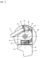
Figur 2- eine Draufsicht auf diese Winkelmeßeinrichtung.
- Figure 1
- an angle measuring device in cross section along the shaft axis and
- Figure 2
- a plan view of this angle measuring device.
Die in den Figuren dargestellte Winkelmeßeinrichtung weist eine Welle 1 zum Anschluß an einen zu messenden Körper auf. Die Verbindung zwischen der Welle 1 und dem zu messenden Körper wird beispielsweise mit einem durch die Welle 1 ragenden Verbindungselement in Form einer Schraube 2 realisiert.The angle measuring device shown in the figures has a
Die Winkelmeßeinrichtung selbst wird über einen Grundkörper 3 an einem weiteren Körper befestigt. Der zu messende Körper ist beispielsweise eine Motorwelle und der weitere Körper das stationäre Motorgehäuse.The angle measuring device itself is attached to a further body via a
In bekannter Weise ist die Welle 1 im Grundkörper 3 drehbar gelagert, wobei an der Weile 1 eine Codescheibe 4 befestigt ist und/oder die Welle 1 über ein Getriebe eine oder mehrere Codescheiben antreibt. Die Codescheibe 4 wird im gezeigten Beispiel lichtelektrisch von einer Abtasteinrichtung 5 abgetastet. Da die Codescheibe 4 im Durchlichtverfahren abgetastet wird, ist hierzu eine Lichtquelle 5.1 im Grundkörper 3 auf einer Seite der Codescheibe 4 und ein Detektor 5.2 auf der anderen Seite der Codescheibe 4 angeordnet. Der Detektor 5.2 befindet sich auf einer Leiterplatte 6 und zwar auf der Seite, die der Codescheibe 4 zugewandt ist. Auf der anderen Seite der Leiterplatte 6 sind elektrische Bauelemente 7 zur Signalformung - beispielsweise Verstärkung und Digitalisierung - der vom Detektor 5.2 gelieferten Abtastsignale angeordnet. Auf der Leiterplatte 6 befindet sich weiterhin ein Teil 8.1 einer Steckverbindung 8. Das korrespondierende Teil 8.2 dieser Steckverbindung 8 ist an einem nach außen führenden Anschlußkabel 9 befestigt.In a known manner, the
Zum Schutz der Winkelmeßeinrichtung ist ein topfförmiges Gehäuse 10 vorgesehen, weiches über den Umfang klemmend am Grundkörper 3 befestigt ist. Im dargestellten Beispiel ist diese Verbindung eine Ringschnappverbindung, bei der im Grundkörper 3 eine Nut 11 und am Gehäuse 10 ein korrespondierender Vorsprung 12 vorgesehen ist.To protect the angle measuring device, a pot-
Mit dem Gehäuse 10 wird die Leiterplatte 6 axial an eine Fläche 13 des Grundkörpers 3 gedrückt. Hierzu weist das Gehäuse 10 einen ringförmigen Absatz 14 auf.With the
Das Gehäuse 10 weist in seinem Innenraum eine Vorrichtung 15 zur Zugentlastung des Anschlußkabels 9 auf. Diese Vorrichtung 15 ist integraler Bestandteil des Gehäuses 10 und besteht aus einer Ringnut 16, in die ein Vorsprung 17 eines mit dem Anschlußkabel 9 fest verbundenen Teiles 18 eingreift, wodurch ein Formschluß zwischen dem Gehäuse 10 und dem Anschlußkabel 9 bzw. dem Teil 18 entsteht. Eine am Anschlußkabel 9 außerhalb der Winkelmeßeinrichtung angreifende Zugkraft wird dadurch nicht auf die Steckverbindung 8 übertragen.The
Das am Anschlußkabel 9 befestigte Teil 18 ist vorzugsweise eine Crimphülse, die eine Verdickung 16 aufweist. Diese Crimphülse 18 ist elektrisch leitend und ist zur sicheren und einfachen Befestigung in einer Passung 19 des Gehäuses 10 geklemmt. Diese Passung 19 ist an die Form der Hülse 18 angepaßt und umgreift diese nach dem Einschnappen teilweise. Die Crimphülse 18 stellt somit eine elektrische Verbindung zwischen dem Schirm des Anschlußkabels 9 und dem Gehäuse 10 her. Das Gehäuse 10 ist dadurch mittels des Anschlußkabels 9 auf einfache Weise mit dem Bezugspotential einer Folgeelektronik (Zähler, Steuerung) verbindbar. Das Gehäuse 10 ist beispielsweise aus einem elektrisch leitenden Kunststoff oder aus einem elektrisch leitend beschichteten Kunststoff hergestellt - insbesondere ein Spritzgußteil. Die Passung 19 und die Ringnut 16 sind derart im Gehäuse 10 angeordnet, daß das Anschlußkabel 9 im Passungsbereich zumindest annähernd senkrecht zur Längsachse X der Winkelmeßrichtung verläuft.The
Zur vollständigen Abschirmung der Bauelemente 7 vor elektromagnetischen Feldern weist das Gehäuse 10 eine Hülse 20 auf. Diese Hülse 20 ist so ausgebildet, daß sie mit einer elektrisch leitenden Fläche 21 der Leiterplatte 6 elektrischen Kontakt hat. Die Leiterplatte 6 weist beispielsweise einen leitenden Ring 21 auf. Die Hülse 20 schützt auch die Leiterplatte 9 und die Bauelemente 7 vor mechanischer Beschädigung.To completely shield the components 7 from electromagnetic fields, the
Zum einfachen Anschluß und Auswechseln des Anschlußkabels 9 ist an einem axialen Ende des Gehäuses 10 eine verschließbare Öffnung 22 vorgesehen. Diese Öffnung 22 ist mit einem aufklappbaren Deckel 23 verschließbar. Der Deckel 23 ist im Beispiel integraler Bestandteile des Gehäuses 10 und über ein Filmscharnier 24 auf- und zuklappbar. Im zugeklappten Zustand wird der Deckel 23 von einem Verriegelungshaken 25 des Gehäuses 10 gehalten, so daß die Winkelmeßeinrichtung allseitig zumindest staubdicht verschlossen und gegen elektromagnetische Felder abgeschirmt ist. In der aufgeklappten Stellung des Deckels 23 - in Figur 1 gestrichelt dargestellt - kann der Hersteller der Winkelmeßeinrichtung sowie der Anwender das Anschlußkabel 9 an das Teil 8.1 der Steckverbindung anschließen und das Anschlußkabel 9 in die Vorrichtung 15 zur Zugentlastung einlegen. Das Gehäuse 10 ist so ausgebildet, daß ausschließlich das Steckverbindungsteil 8.1 über eine Gehäuseöffnung 26 bei geöffnetem Deckel 23 von außen zugänglich ist. Die weiteren Bauelemente 7 auf der Leiterplatte 6 sowie die Leiterplatte 6 selbst sind auch im geöffneten Zustand des Deckels 23 vom Gehäuse 10 abgedeckt.For easy connection and replacement of the connecting
Um eine einfache Montage der Welle 1 der Winkelmeßeinrichtung an eine zu messende Welle zu gewährleisten, ist die Schraube 2 ebenfalls bei geöffnetem Deckel 23 zugänglich. Die Hülse 20 verhindert eine Beschädigung der Leiterplatte 6 und der Bauelemente 7, wenn der Anwender die Schraube 2 mit einem Werkzeug von der Öffnung 22 her betätigt.In order to ensure simple mounting of the
Die Vorrichtung 15 zur Zugentlastung ist vollständig innerhalb der radialen Außenkontur des Gehäuses 10 mit Abstand zur radialen Außenkontur des Grundkörpers 3 und Gehäuses 10 angeordnet. Dies hat den Vorteil, daß das Anschlußkabel 9 innerhalb eines Bereiches der Winkelmeßeinrichtung selbst von der Vorrichtung 15 bis zur Außenkontur beliebig gebogen werden kann. Dadurch kann ein beliebig radialer oder auch axialer Kabelausgang gewählt werden. Die Fixierung des Anschlußkabels 9 für die Zugentlastung muß von der Außenkontur des Gehäuses 10 zumindest entsprechend dem minimal zulässigen Biegeradius des Anschlußkabels 9 beabstandet sein. Besonders vorteilhaft ist es, wenn die Vorrichtung 15 zur Zugentlastung - also die Mittel zur Fixierung des Anschlußkabels 9 am Gehäuse 10 - innerhalb der von außen zugänglichen und verschließbaren Gehäuseöffnung 26 angeordnet sind.The
Zusammenfassend hat die erfindungsgemäß ausgebildete Winkelmeßeinrichtung folgende Vorteile:
- flexibler Kabelausgang bei kleiner Baugröße;
- kostengünstige Herstellung, da einstückiges Gehäuse 10
mit Deckel 23; - vollständiger Berührungsschutz der Leiterplatte 6 auch während des Kabelanschlusses;
sichere Zugentlastung 15 und gute elektrische Verbindung des Anschlußkabels 9mit dem Gehäuse 10;- kein Spezialwerkzeug zum Öffnen und Schließen des Deckels 23 erforderlich;
- Zusatzfunktionen wie zum Beispiel Klemmung der Leiterplatte 6 in
Gehäuse 10 integriert; - sichere Zugentlastung unabhängig von der Stellung des Deckels 23 gewährleistet.
- flexible cable outlet with small size;
- Cost-effective production, since one-
piece housing 10 withcover 23; - complete protection against contact of the printed
circuit board 6 even during the cable connection; -
safe strain relief 15 and good electrical connection of the connectingcable 9 to thehousing 10; - no special tools required to open and close the
cover 23; - Additional functions such as clamping the
circuit board 6 integrated in thehousing 10; - guaranteed strain relief regardless of the position of the
cover 23 guaranteed.
Claims (19)
Priority Applications (1)
| Application Number | Priority Date | Filing Date | Title |
|---|---|---|---|
| DE29624207U DE29624207U1 (en) | 1995-11-21 | 1996-09-28 | Angle measuring system |
Applications Claiming Priority (2)
| Application Number | Priority Date | Filing Date | Title |
|---|---|---|---|
| DE19543372 | 1995-11-21 | ||
| DE1995143372 DE19543372C5 (en) | 1995-11-21 | 1995-11-21 | angle measuring device |
Publications (2)
| Publication Number | Publication Date |
|---|---|
| EP0776065A1 true EP0776065A1 (en) | 1997-05-28 |
| EP0776065B1 EP0776065B1 (en) | 2000-01-05 |
Family
ID=7778016
Family Applications (1)
| Application Number | Title | Priority Date | Filing Date |
|---|---|---|---|
| EP19960115610 Expired - Lifetime EP0776065B1 (en) | 1995-11-21 | 1996-09-28 | Angle measuring device |
Country Status (2)
| Country | Link |
|---|---|
| EP (1) | EP0776065B1 (en) |
| DE (1) | DE59604109D1 (en) |
Cited By (5)
| Publication number | Priority date | Publication date | Assignee | Title |
|---|---|---|---|---|
| EP1167916A2 (en) * | 2000-06-27 | 2002-01-02 | Dr. Johannes Heidenhain GmbH | Housing for angle measuring device |
| EP1672327A2 (en) * | 2004-12-17 | 2006-06-21 | Dr. Johannes Heidenhain GmbH | Angle measuring device |
| EP1672326A1 (en) * | 2004-12-17 | 2006-06-21 | Dr. Johannes Heidenhain GmbH | Angle measurement device |
| EP1703286A1 (en) * | 2005-03-16 | 2006-09-20 | Prüftechnik Dieter Busch Ag | Vibration sensor or transducer |
| US7438588B2 (en) | 2006-12-13 | 2008-10-21 | Renco Encoders, Inc. | Encoder and encoder cover with strain relief |
Citations (3)
| Publication number | Priority date | Publication date | Assignee | Title |
|---|---|---|---|---|
| DE3446911A1 (en) * | 1984-12-21 | 1986-07-03 | Bosch-Siemens Hausgeräte GmbH, 7000 Stuttgart | Electrical hand apparatus for stirring and/or cutting |
| DE4304032A1 (en) * | 1993-02-11 | 1994-08-18 | Heidenhain Gmbh Dr Johannes | Angle measuring device |
| EP0653811A1 (en) * | 1993-11-17 | 1995-05-17 | Thomas & Betts Corporation | Electrical connector strain relief |
-
1996
- 1996-09-28 DE DE59604109T patent/DE59604109D1/en not_active Expired - Lifetime
- 1996-09-28 EP EP19960115610 patent/EP0776065B1/en not_active Expired - Lifetime
Patent Citations (3)
| Publication number | Priority date | Publication date | Assignee | Title |
|---|---|---|---|---|
| DE3446911A1 (en) * | 1984-12-21 | 1986-07-03 | Bosch-Siemens Hausgeräte GmbH, 7000 Stuttgart | Electrical hand apparatus for stirring and/or cutting |
| DE4304032A1 (en) * | 1993-02-11 | 1994-08-18 | Heidenhain Gmbh Dr Johannes | Angle measuring device |
| EP0653811A1 (en) * | 1993-11-17 | 1995-05-17 | Thomas & Betts Corporation | Electrical connector strain relief |
Cited By (11)
| Publication number | Priority date | Publication date | Assignee | Title |
|---|---|---|---|---|
| EP1167916A2 (en) * | 2000-06-27 | 2002-01-02 | Dr. Johannes Heidenhain GmbH | Housing for angle measuring device |
| JP2002048532A (en) * | 2000-06-27 | 2002-02-15 | Dr Johannes Heidenhain Gmbh | Instrument for measuring angle |
| US6617571B2 (en) | 2000-06-27 | 2003-09-09 | Dr. Johannes Heidenhain Gmbh | Rotary encoder |
| EP1167916A3 (en) * | 2000-06-27 | 2003-10-22 | Dr. Johannes Heidenhain GmbH | Housing for angle measuring device |
| EP1672327A2 (en) * | 2004-12-17 | 2006-06-21 | Dr. Johannes Heidenhain GmbH | Angle measuring device |
| EP1672326A1 (en) * | 2004-12-17 | 2006-06-21 | Dr. Johannes Heidenhain GmbH | Angle measurement device |
| US7308765B2 (en) | 2004-12-17 | 2007-12-18 | Dr. Johannes Heidenhain Gmbh | Angle-measuring arrangement |
| EP1672327A3 (en) * | 2004-12-17 | 2011-02-09 | Dr. Johannes Heidenhain GmbH | Angle measuring device |
| EP1703286A1 (en) * | 2005-03-16 | 2006-09-20 | Prüftechnik Dieter Busch Ag | Vibration sensor or transducer |
| US7513162B2 (en) | 2005-03-16 | 2009-04-07 | Prueftechnik Dieter Busch Ag | Vibration sensor or measurement detector |
| US7438588B2 (en) | 2006-12-13 | 2008-10-21 | Renco Encoders, Inc. | Encoder and encoder cover with strain relief |
Also Published As
| Publication number | Publication date |
|---|---|
| DE59604109D1 (en) | 2000-02-10 |
| EP0776065B1 (en) | 2000-01-05 |
Similar Documents
| Publication | Publication Date | Title |
|---|---|---|
| EP1167916B1 (en) | Housing for angle measuring device | |
| EP1703620B1 (en) | Electric drive | |
| DE112009001624T5 (en) | Cable attachment device for electrical appliances | |
| EP1183167B1 (en) | Device for transmitting energy | |
| WO1993013424A1 (en) | Device for measuring rotational parameters | |
| EP1703617B1 (en) | Electric drive | |
| DE19723430A1 (en) | Steering sensor unit for motor vehicle | |
| DE19913262A1 (en) | Angle measuring equipment for measuring rotations of shaft or as rotation shaft encoders has part of connecting cable fastened by holder on housing while holder may release tension of connecting cable | |
| DE102020104511A1 (en) | Charging socket for an electric vehicle | |
| DE19543372C5 (en) | angle measuring device | |
| EP0610869B1 (en) | Angle measuring device | |
| EP0776065B1 (en) | Angle measuring device | |
| DE4300663C1 (en) | Optical steering angle sensor for vehicle | |
| EP0187902B1 (en) | Housing for an electrical device | |
| EP1344034A1 (en) | Pressure measuring device | |
| DE4413496C1 (en) | Angle sensor for relative position of automobile components | |
| DE69923807T2 (en) | Apparatus for measuring a physical quantity related to the rotation of an organ | |
| WO2005088320A1 (en) | Adapter device for testing electrical consumers, in particular for or in a motor vehicle | |
| DE102020213525A1 (en) | Torque and angle sensor assembly | |
| DE2428761C3 (en) | Diagnostic device | |
| EP2447973B1 (en) | Electric addressing device | |
| EP3734298B1 (en) | Measuring assembly for measuring an electrical current | |
| DE19622228C1 (en) | Device for signal transmission to or from motor vehicle steering column | |
| DE29624207U1 (en) | Angle measuring system | |
| DE19913787B4 (en) | encoders |
Legal Events
| Date | Code | Title | Description |
|---|---|---|---|
| PUAI | Public reference made under article 153(3) epc to a published international application that has entered the european phase |
Free format text: ORIGINAL CODE: 0009012 |
|
| 17P | Request for examination filed |
Effective date: 19970312 |
|
| AK | Designated contracting states |
Kind code of ref document: A1 Designated state(s): DE FR GB IT |
|
| 17Q | First examination report despatched |
Effective date: 19980512 |
|
| GRAG | Despatch of communication of intention to grant |
Free format text: ORIGINAL CODE: EPIDOS AGRA |
|
| GRAH | Despatch of communication of intention to grant a patent |
Free format text: ORIGINAL CODE: EPIDOS IGRA |
|
| GRAH | Despatch of communication of intention to grant a patent |
Free format text: ORIGINAL CODE: EPIDOS IGRA |
|
| ITF | It: translation for a ep patent filed |
Owner name: DE DOMINICIS & MAYER S.R.L. |
|
| GRAA | (expected) grant |
Free format text: ORIGINAL CODE: 0009210 |
|
| AK | Designated contracting states |
Kind code of ref document: B1 Designated state(s): DE FR GB IT |
|
| ET | Fr: translation filed | ||
| REF | Corresponds to: |
Ref document number: 59604109 Country of ref document: DE Date of ref document: 20000210 |
|
| GBT | Gb: translation of ep patent filed (gb section 77(6)(a)/1977) |
Effective date: 20000228 |
|
| PLBE | No opposition filed within time limit |
Free format text: ORIGINAL CODE: 0009261 |
|
| STAA | Information on the status of an ep patent application or granted ep patent |
Free format text: STATUS: NO OPPOSITION FILED WITHIN TIME LIMIT |
|
| 26N | No opposition filed | ||
| REG | Reference to a national code |
Ref country code: GB Ref legal event code: IF02 |
|
| PGFP | Annual fee paid to national office [announced via postgrant information from national office to epo] |
Ref country code: IT Payment date: 20100922 Year of fee payment: 15 |
|
| PGFP | Annual fee paid to national office [announced via postgrant information from national office to epo] |
Ref country code: FR Payment date: 20110928 Year of fee payment: 16 Ref country code: GB Payment date: 20110920 Year of fee payment: 16 |
|
| PGFP | Annual fee paid to national office [announced via postgrant information from national office to epo] |
Ref country code: DE Payment date: 20120921 Year of fee payment: 17 |
|
| GBPC | Gb: european patent ceased through non-payment of renewal fee |
Effective date: 20120928 |
|
| REG | Reference to a national code |
Ref country code: FR Ref legal event code: ST Effective date: 20130531 |
|
| PG25 | Lapsed in a contracting state [announced via postgrant information from national office to epo] |
Ref country code: GB Free format text: LAPSE BECAUSE OF NON-PAYMENT OF DUE FEES Effective date: 20120928 |
|
| PG25 | Lapsed in a contracting state [announced via postgrant information from national office to epo] |
Ref country code: FR Free format text: LAPSE BECAUSE OF NON-PAYMENT OF DUE FEES Effective date: 20121001 Ref country code: IT Free format text: LAPSE BECAUSE OF NON-PAYMENT OF DUE FEES Effective date: 20120928 |
|
| REG | Reference to a national code |
Ref country code: DE Ref legal event code: R119 Ref document number: 59604109 Country of ref document: DE Effective date: 20140401 |
|
| PG25 | Lapsed in a contracting state [announced via postgrant information from national office to epo] |
Ref country code: DE Free format text: LAPSE BECAUSE OF NON-PAYMENT OF DUE FEES Effective date: 20140401 |