EP1672303A1 - Drying apparatus for clothing knitted or woven fabric - Google Patents
Drying apparatus for clothing knitted or woven fabric Download PDFInfo
- Publication number
- EP1672303A1 EP1672303A1 EP04772059A EP04772059A EP1672303A1 EP 1672303 A1 EP1672303 A1 EP 1672303A1 EP 04772059 A EP04772059 A EP 04772059A EP 04772059 A EP04772059 A EP 04772059A EP 1672303 A1 EP1672303 A1 EP 1672303A1
- Authority
- EP
- European Patent Office
- Prior art keywords
- drying
- rack
- woven
- knitted fabric
- drying device
- Prior art date
- Legal status (The legal status is an assumption and is not a legal conclusion. Google has not performed a legal analysis and makes no representation as to the accuracy of the status listed.)
- Withdrawn
Links
Images



Classifications
-
- F—MECHANICAL ENGINEERING; LIGHTING; HEATING; WEAPONS; BLASTING
- F26—DRYING
- F26B—DRYING SOLID MATERIALS OR OBJECTS BY REMOVING LIQUID THEREFROM
- F26B13/00—Machines and apparatus for drying fabrics, fibres, yarns, or other materials in long lengths, with progressive movement
-
- F—MECHANICAL ENGINEERING; LIGHTING; HEATING; WEAPONS; BLASTING
- F26—DRYING
- F26B—DRYING SOLID MATERIALS OR OBJECTS BY REMOVING LIQUID THEREFROM
- F26B21/00—Arrangements for supplying or controlling air or other gases for drying solid materials or objects
- F26B21/20—Circulating air or gases in closed cycles, e.g. wholly within the drying enclosure
- F26B21/202—Circulating air or gases in closed cycles, e.g. wholly within the drying enclosure with means for changing the flow pattern, e.g. by reversing gas flow or by moving the materials or objects through subsequent compartments, at least two of which have a different flow direction
- F26B21/204—Circulating air or gases in closed cycles, e.g. wholly within the drying enclosure with means for changing the flow pattern, e.g. by reversing gas flow or by moving the materials or objects through subsequent compartments, at least two of which have a different flow direction by using movable fan units
-
- F—MECHANICAL ENGINEERING; LIGHTING; HEATING; WEAPONS; BLASTING
- F26—DRYING
- F26B—DRYING SOLID MATERIALS OR OBJECTS BY REMOVING LIQUID THEREFROM
- F26B13/00—Machines and apparatus for drying fabrics, fibres, yarns, or other materials in long lengths, with progressive movement
- F26B13/06—Machines and apparatus for drying fabrics, fibres, yarns, or other materials in long lengths, with progressive movement with movement in a sinuous or zig-zag path
-
- F—MECHANICAL ENGINEERING; LIGHTING; HEATING; WEAPONS; BLASTING
- F26—DRYING
- F26B—DRYING SOLID MATERIALS OR OBJECTS BY REMOVING LIQUID THEREFROM
- F26B3/00—Drying solid materials or objects by processes involving the application of heat
-
- F—MECHANICAL ENGINEERING; LIGHTING; HEATING; WEAPONS; BLASTING
- F26—DRYING
- F26B—DRYING SOLID MATERIALS OR OBJECTS BY REMOVING LIQUID THEREFROM
- F26B3/00—Drying solid materials or objects by processes involving the application of heat
- F26B3/28—Drying solid materials or objects by processes involving the application of heat by radiation, e.g. from the sun
-
- F—MECHANICAL ENGINEERING; LIGHTING; HEATING; WEAPONS; BLASTING
- F26—DRYING
- F26B—DRYING SOLID MATERIALS OR OBJECTS BY REMOVING LIQUID THEREFROM
- F26B3/00—Drying solid materials or objects by processes involving the application of heat
- F26B3/28—Drying solid materials or objects by processes involving the application of heat by radiation, e.g. from the sun
- F26B3/283—Drying solid materials or objects by processes involving the application of heat by radiation, e.g. from the sun in combination with convection
Definitions
- the present invention relates to a dryer apparatus for use in a woven and knitted fabric, and more specifically to a dryer apparatus used for drying the woven and knitted fabric or the like, in which medical agent is applied when pretreatment is performed before inkjet printing is carried out, or for drying the woven and knitted fabric as a midterm-drying after the inkjet printing is carried out.
- a pattern or design is drawn in a woven and knitted fabric, such as knit, sweater made of cloth, a clothing fabric, or the like
- printings are performed by means of various types of printing machines, such as a flat screen, rotary screen, roller or the like.
- Products made by such kinds of printings are commercialized after passing through processes such as a drying, a color appearance, a soaping, finishing, after the printing.
- a plate has to be separately made for each of colors to be printed by means of work such as tracing of an original picture for use in printing, reproduction or the like, requiring much trouble, costs, and a term.
- a dryer apparatus for use in such printed materials or small lot production as printing objects does not exist heretofore.
- the dryer apparatus includes a conveyer, and warm wind is blown to the long-sheet-shaped woven and knitted fabric. Therefore, the size of the dryer apparatus is too large and the dryer apparatus is not suitable for sample printings or small lot production (Refer to Patent Document 2).
- Patent Document 1 International Patent Publication No. WO03/031190
- Patent Document 2 Japanese Unexamined Patent Application Publication No. 9-133464
- the present invention is proposed in light of the above-described problems, and an object of the present invention is to provide a dryer apparatus for use in a woven and knitted fabric regardless of whether the surface to be printed is one side surface or both side surfaces, and the dryer apparatus for use in a woven and knitted fabric that is applicable for clothing made of knit, the woven and knitted fabric, or even a small product of small lot production, and that is capable of performing preferable dryings. Further, the object of the present invention is to provide a dryer apparatus that can dry the woven and knitted fabric, specifically, even a thickly formed knitted fabric with good efficiency in a short period of time.
- a dryer apparatus for use in a woven and knitted fabric with respect to the present invention is most largely characterized in that the dryer apparatus for use in woven and knitted fabric includes a frame including, a first drying rack disposed at an upper step; at least one step of a second drying rack disposed at a step lower that the first rack; in which each of the drying rack is formed of a drying surface having permeability, and the frame further includes a first drying device disposed above the first drying rack; a second drying device disposed above the second rack; in which each of the drying devices is formed of a drying irradiation surface for irradiating heat ray and/or heated air, and in which the drying devices are constructed to be movable for reciprocation along the drying surface of the drying rack by means of a driving device, and in which the drying device disposed above the second drying rack is constructed to be able to switch a direction of the drying irradiation surface from downside to upside and to be able to dry from both of an upper and
- the dryer apparatus for use in the woven and knitted fabric is characterized in that the first and the second drying devices disposed in an up-and-down direction are controlled for sliding by means of the same driving device, or the woven and knitted fabric to be performed for drying treatment is moisturized by means of liquid for treatment performed before printing, or in printing. Furthermore, the dryer apparatus for use in the woven and knitted fabric is characterized in that the drying device includes a device for irradiating a heat ray such as an infrared ray, or the like, and the second drying device further includes a drip-proof cover at a drying irradiation surface portion thereof.
- dryer apparatus for use in the woven and knitted fabric is characterized in that the drying device serves as a device for irradiating the heat ray and/or hot wind from the drying irradiation surface, and includes a first drying stage to perform drying by the heat ray, and a second drying stage to perform drying by the heat ray and the hot wind, in which the reciprocating movement of the drying device at the first drying stage is performed at low speed, and the reciprocating movement of the drying device at the second drying stage is performed at speed faster than the speed of the reciprocating movement at the first drying stage.
- a drying surface formed of a drying surface having ventilation is provided at least two steps of a first drying rack and a second drying rack, and when only one face of the woven and knitted fabric is printed, only the printed surface or a treated surface is dried by means of drying surface of each of the drying racks and thereby a large number of the woven and knitted fabrics can be dried, and when both side surfaces of the woven and knitted fabric are printed, a drying irradiation surface at a lower side is upwardly turned around. Therefore, there is an advantage such that the woven and knitted fabric can be efficiently dried from above and below the first drying rack without patches.
- a both-surface drying can be performed not only for the woven and knitted fabric of which both surfaces are printed, but also for a thickly formed woven and knitted fabric, a sweater having a front side knitted fabric and a backside knitted fabric, or the like.
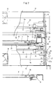
- FIG. 1 is an elevation schematically showing a dryer apparatus for use in the woven and a knitted fabric, and numeral 1 in the figure entirely denotes the apparatus.
- the dryer apparatus 1 for the woven and knitted fabric is configured such that a first drying rack 3a is disposed at an upper part of the frame 2 and a second drying rack 3b is disposed at a lower part of the frame 2, respectively, by means of a supporting member 6 in an up-and-down direction.
- a first drying device 4a is located above the first drying rack 3a disposed at the upper part of the frame 2 and a second drying device 4b is located above the second drying rack 3b disposed at the lower part of the frame 2.
- the first and second drying devices, 4a and 4b are configured to be driven for reciprocating movement above the first and second drying racks, 3a and 3b, by means of a driving device 5, described later and shown in FIG. 5.
- each of the first and second drying racks, 3a and 3b is configured to be independently pulled out and taken out from the frame 2 by means of sliding at a portion of the supporting member, as shown in FIG. 2.
- the aforementioned first and second drying devices, 4a and 4b are configured such that a moving bracket 9 that moves from one end of the first and second drying racks, 3a and 3b, to the other end thereof by means of the driving device 5 is disposed at both sides of the supporting member 6 of the first and second drying racks, 3a and 3b.
- a side board 10 of the first drying device 4a and a side board 11 of the second drying device 4b are provided, and across each of the side boards, 10 and 10, 11 and 11, beams, 12 and 13, having a closed section, and covers, 14 and 15, having approximately C-shaped section are constructed and a plurality of fans 16, 16, and 16, for use in air sending are attached at a side face portion of the covers, 14 and 15, at even intervals (Refer to FIG. 1) .
- a reflecting plate 18 having a trapezoid-shaped section, one side of which opens to serve as a drying irradiation surface 17 is attached to the beams, 12 and 13, via a bracket 19.
- a heater 20 is attached to an inside of the reflecting plate 18 (Refer to FIG. 2).
- the heater 20 to be mounted on the first and second drying devices, 4a and 4b are configured such that the drying device irradiates a heat ray, such as an infrared ray, or the like having a wave form of from 780 nm to 1 mm.
- a heat ray such as an infrared ray, or the like having a wave form of from 780 nm to 1 mm.
- the first and second drying devices, 4a and 4b are formed by attaching a plurality of far-infrared ray heater having a predetermined dimension in a line like manner.
- a drip-proof cover 21 formed of heat resistance glass is attached to an opening portion of the reflecting plate 18 of the second drying device 4b, and the second drying device 4b is configured to be rotatable between the side board 11 and the moving bracket 9 by means of a rotation mechanism 22 at 180 degrees.
- the rotation mechanism 22 of the aforementioned second drying device 4b is configured such that a rotation pivot hole 23 is formed in the side board 11, as shown in FIG. 2. Further, screw holes, 24 and 24, for fixing are formed at two places, i.e., an upper portion and a lower portion on a concentric circle around the rotation pivot hole 23.
- the side board 11 is rotatably supported because a pivot shaft 25 being protruded from the moving bracket 9 is fitted into the rotation pivot hole 23. Further, the position of the drying device 4b of the lower side is configured to be fixed by means of fitting a butterfly bolt 26 inserted from the moving bracket 9 into one of the screw holes 24 for fixing.
- a numeral 27 in the figure denotes an assisting member for positioning having a knob portion 27a.
- a tip end portion of the assisting member 27 is kept under tension to be protruding toward the side board 11 side by means of a spring (not shown) built in the tip end side portion (below the neck portion) from the knob portion 27a in the assisting member 27.
- the drying irradiation surface 17 at a lower side is configured to be located in a manner so as to be closer to the drying rack than the drying irradiation surface 17 at an upper side is, namely located to a asymmetry position.
- the driving device 5 that drives for sliding the aforementioned first and second drying device 4a, and 4b, is composed of an electric motor 30 fixed to the frame 2, a drive belt 31 provided across an entire length of the first and second drying racks, 3a and 3b, a transmission apparatus 33 for transmitting rotation of the electric motor 30 to a pulley 32 at an end of the drive belt 31 at decreased speed, and a clamp 35 of a carrier 34 provided at a middle portion of the moving bracket 9 is connected to the drive belt 31, as shown in a schematic view in FIG. 6.
- the carrier 34 spans across supporting beams 36 at a side of the first drying rack 3a from the front side to the rear side of the frame 2, and is movably supported by a guide rail 37 attached to an upper surface of the supporting beam 36 via a slider 38, as shown in FIG. 2.
- the electric motor 30 is controlled by means of an automatic control apparatus (not shown) on the basis of signals from various kinds of sensors (though not shown, for example, a temperature sensor, an end position sensor for the clothing fabric, or the like). Accordingly, an output power of the fan 16 for use in air sending, or that of the heater 20 of the first and second drying devices, 4a and 4b, and a dimension or speed of a reciprocating movement of the first and second drying devices, 4a and 4b, are controlled.
- FIG. 6 corresponds to a front side of the drying apparatus 1, and the left of FIG. 6 is an illustration showing a state, in which a second drying device 4b is upwardly turned around and in which the first drying rack 3a is dried from above and below, whereas the right of FIG. 6 is a schematic illustration showing the second drying device 4b in the middle of being upwardly turned around.
- liquid for pretreatment is applied to the clothing fabric (woven and knitted fabric) portion of a sweater or the like to be inkjet printed and the clothing fabric portion is brought to a state to be moisturized.
- the clothing fabric is mounted on each of the first and second drying racks, 3a and 3b, in a state that the clothing fabric is developed such that the front side portion to which the pretreatment is applied faces upward, namely, faces each of the drying irradiation surfaces 17 of the first and second drying devices, 4a and 4b.
- the clothing fabric is treated by the dimension or speed of the reciprocating movement of the first and second drying devices, 4a and 4b, the output power of the heater 20 and the air volume of the fans, 16, 16, and 16, for use in the air sending, which is set by means of the automatic control apparatus on the basis of signals from various kinds of sensors, and is brought to predetermined humidity.
- an automatic control for the dimension, the speed, or the number of the reciprocating movement of the first and second drying device, 4a and 4b, or an output control of the output power of the heater 20 is automatically controlled by means of a program set in advance to the automatic control apparatus by the temperature sensor, a moisture percentage sensor, a thickness sensor for the clothing fabric, or the like, the program can be modified by hand and performed.
- the output power of the aforementioned heater 20, and the air volume or the like of the fans, 16, 16, and 16, for sending air of the first and second drying devices, 4a and 4b can be adjusted to be different to each other and excess or deficiency of drying can be prevented.
- the drying of the clothing fabric is performed by using only the heater 20 and by causing the reciprocating movement of the first and second drying devices, 4a and 4b, to be slow in order to prevent medical agent from being affected by wind from the fan 16 for sending air.
- moving speed of the first and second drying devices, 4a and 4b is gradually increased and the drying is accelerated.
- the end position sensor for the clothing fabric detects an end portion of the clothing fabric mounted on the first and second drying racks, 3a and 3b, in a moving direction
- the movement of the first and second drying devices, 4a and 4b is reversed so as to prevent needless output of the heater 20 and the fan 16 for sending air, and efficiency of the dimension of the reciprocating movement.
- the end position sensor for the clothing fabric detects the end portion in a width direction perpendicular to the moving direction of the clothing fabric which is mounted on the first and second drying racks, 3a and 3b, the output power of the heater 20 at a part positioned outside of the end of the clothing fabric is turned off, resulting in reducing power consumption.
- the portion to be inkjet printed is a front side portion and a backside portion (including an entire periphery) of the sweater, or the like, for example, the clothing fabric is mounted on the first drying rack 3a in a developed state, and the second drying device 4b is turned around.
- the second drying device 4b When the knob portion 27a of the assisting member 27 for positioning is pulled after the butterfly bolt 26 is loosened, and a tip end portion of the knob portion 27a is brought to a state to be pulled out from a screw hole 21 for fixing of the side board 11, the second drying device 4b is rotated by small force around the pivot shaft 25. Further, the second drying device 4b is turned around to reach a state for the drying irradiation surface 17 to be proximally in contact with a lower face of the first drying rack 3a, as shown in the figure at the left in FIG. 6, and in FIGs. 1 and 2, after passing through a state, shown in the figure at the right in FIG. 6.
- the butterfly bolt when only the butterfly bolt is operated for rotation in a direction to be screwed, the butterfly bolt can be screwed into the screw hole 24 for fixing and the drying device 4b can be firmly fixed in a state that the drying irradiating surface 17 is proximally in contact with a lower face of the first drying rack 3a at the upper side.
- the drying irradiation surface 17 is fixed in a state that the same is proximally in contact with the lower face of the drying rack 3a at the upper side, the dimension and the speed of the reciprocating drive for the first and second drying device, 4a and 4b, the output power of the heater 20, the air volume of the fans, 16, 16, and 16, for sending air, or the like is automatically controlled by means of the program preset to the automatic control apparatus by the temperature sensor, a moisture percentage sensor, a thickness sensor for the clothing fabric, or the like, and the drying is performed.
- the reason why the drying irradiation surface 17 is configured to be in closer contact with the drying rack 3a than the drying irradiation surface 17 at the upper side when the drying device 4a of the lower side is upwardly turned around is to compensate with the heat ray irradiated by the drying irradiation surface 17 of the drying device 4b at the lower side, or the air volume which are interrupted by the drying surface 8 made of metal and the drip-proof cover 21.
- the drip-proof cover 21 spread over the drying irradiation surface 17 of the drying device 4a at the lower side is to prevent the heater 20 from causing to short circuit by a droplet dripping down from the clothing fabric mounted on the drying rack 3a, or to prevent the heater 20 from adhering of lint or moisture.
- the pretreatment liquid applied to the clothing fabric before printing is explained as an example.
- the dryer apparatus for use in the woven and knitted fabric can be also used for a midterm-drying.
- the drying rack being constructed to be two steps of the lower side and upper side is illustrated, however, the present invention can be carried out by providing three or more drying racks and by providing the drying device corresponding to the drying rack, without being limited to such a construction.
Landscapes
- Engineering & Computer Science (AREA)
- Mechanical Engineering (AREA)
- General Engineering & Computer Science (AREA)
- Life Sciences & Earth Sciences (AREA)
- Microbiology (AREA)
- Textile Engineering (AREA)
- Treatment Of Fiber Materials (AREA)
- Drying Of Solid Materials (AREA)
Abstract
A dryer apparatus for use in a woven and knitted fabric is constructed such that a first drying rack disposed at an upper step, and at least one step of a second drying rack disposed at a lower step thereof are provided in a frame. Each of the drying racks is formed of a drying surface having ventilation. A first drying device is disposed above the first drying rack, and a second drying device is disposed above the second rack. Each of the drying devices is formed of a drying irradiation surface for irradiating heat ray and/or heated air, and is constructed to be movable for reciprocation along the drying surface of the drying rack by means of a driving device. The drying device disposed above the second drying rack is constructed to be able to switch a direction of the drying irradiation surface from downside to upside and to be able to dry from both of an upper and a lower surface of the first drying rack.
Description
- The present invention relates to a dryer apparatus for use in a woven and knitted fabric, and more specifically to a dryer apparatus used for drying the woven and knitted fabric or the like, in which medical agent is applied when pretreatment is performed before inkjet printing is carried out, or for drying the woven and knitted fabric as a midterm-drying after the inkjet printing is carried out.
- Generally, in a case when a pattern or design is drawn in a woven and knitted fabric, such as knit, sweater made of cloth, a clothing fabric, or the like, printings are performed by means of various types of printing machines, such as a flat screen, rotary screen, roller or the like.
- Products made by such kinds of printings are commercialized after passing through processes such as a drying, a color appearance, a soaping, finishing, after the printing.
- However, in such kinds of printings, a plate has to be separately made for each of colors to be printed by means of work such as tracing of an original picture for use in printing, reproduction or the like, requiring much trouble, costs, and a term.
- Further, at a time for adjusting of color paste for each of the colors and coloration change, washing work for each of the plates is also necessary and therefor it has been also a cause of lowering of the productivity.
- Accordingly, as the applicant of the present invention has proposed earlier, there have been inkjet printers for mainly printing a design and a pattern of shape on knit or clothes made of the woven and knitted fabric, or small product as printing object for inkjet printing, and the printed materials are naturally dried after a medical agent is applied for the pretreatment, or after the pattern of shape is printed. However, in particular, when both of surfaces are printed, each of the surfaces is naturally dried one by one, and therefore it has required appreciably long time (Refer to Patent Document 1).
- A dryer apparatus for use in such printed materials or small lot production as printing objects does not exist heretofore.
- For example, in a dryer apparatus described in Japanese Unexamined Patent Application Publication No. 9-133464, applied by Toray Industries, Inc., the dryer apparatus includes a conveyer, and warm wind is blown to the long-sheet-shaped woven and knitted fabric. Therefore, the size of the dryer apparatus is too large and the dryer apparatus is not suitable for sample printings or small lot production (Refer to Patent Document 2).
- Patent Document 1: International Patent Publication No. WO03/031190
- Patent Document 2: Japanese Unexamined Patent Application Publication No. 9-133464
- The present invention is proposed in light of the above-described problems, and an object of the present invention is to provide a dryer apparatus for use in a woven and knitted fabric regardless of whether the surface to be printed is one side surface or both side surfaces, and the dryer apparatus for use in a woven and knitted fabric that is applicable for clothing made of knit, the woven and knitted fabric, or even a small product of small lot production, and that is capable of performing preferable dryings. Further, the object of the present invention is to provide a dryer apparatus that can dry the woven and knitted fabric, specifically, even a thickly formed knitted fabric with good efficiency in a short period of time.
- To achieve the above-described problems, a dryer apparatus for use in a woven and knitted fabric with respect to the present invention is most largely characterized in that the dryer apparatus for use in woven and knitted fabric includes a frame including, a first drying rack disposed at an upper step; at least one step of a second drying rack disposed at a step lower that the first rack; in which each of the drying rack is formed of a drying surface having permeability, and the frame further includes a first drying device disposed above the first drying rack; a second drying device disposed above the second rack; in which each of the drying devices is formed of a drying irradiation surface for irradiating heat ray and/or heated air, and in which the drying devices are constructed to be movable for reciprocation along the drying surface of the drying rack by means of a driving device, and in which the drying device disposed above the second drying rack is constructed to be able to switch a direction of the drying irradiation surface from downside to upside and to be able to dry from both of an upper and a lower surfaces of the first drying rack.
- Further, the dryer apparatus for use in the woven and knitted fabric is characterized in that the first and the second drying devices disposed in an up-and-down direction are controlled for sliding by means of the same driving device, or the woven and knitted fabric to be performed for drying treatment is moisturized by means of liquid for treatment performed before printing, or in printing. Furthermore, the dryer apparatus for use in the woven and knitted fabric is characterized in that the drying device includes a device for irradiating a heat ray such as an infrared ray, or the like, and the second drying device further includes a drip-proof cover at a drying irradiation surface portion thereof. Still further, dryer apparatus for use in the woven and knitted fabric is characterized in that the drying device serves as a device for irradiating the heat ray and/or hot wind from the drying irradiation surface, and includes a first drying stage to perform drying by the heat ray, and a second drying stage to perform drying by the heat ray and the hot wind, in which the reciprocating movement of the drying device at the first drying stage is performed at low speed, and the reciprocating movement of the drying device at the second drying stage is performed at speed faster than the speed of the reciprocating movement at the first drying stage.
- According to a dryer apparatus for use in a woven and knitted fabric of the present invention, a drying surface formed of a drying surface having ventilation is provided at least two steps of a first drying rack and a second drying rack, and when only one face of the woven and knitted fabric is printed, only the printed surface or a treated surface is dried by means of drying surface of each of the drying racks and thereby a large number of the woven and knitted fabrics can be dried, and when both side surfaces of the woven and knitted fabric are printed, a drying irradiation surface at a lower side is upwardly turned around. Therefore, there is an advantage such that the woven and knitted fabric can be efficiently dried from above and below the first drying rack without patches.
- In addition, since the woven and knitted fabric can be dried from above and below the first drying rack, a both-surface drying can be performed not only for the woven and knitted fabric of which both surfaces are printed, but also for a thickly formed woven and knitted fabric, a sweater having a front side knitted fabric and a backside knitted fabric, or the like.
- Hereinbelow, a dryer apparatus for use in a woven and knitted fabric with respect to the present invention is explained on the basis of the drawings.
- FIG. 1 is an elevation schematically showing a dryer apparatus for use in the woven and a knitted fabric, and numeral 1 in the figure entirely denotes the apparatus.
- The dryer apparatus 1 for the woven and knitted fabric is configured such that a
first drying rack 3a is disposed at an upper part of theframe 2 and asecond drying rack 3b is disposed at a lower part of theframe 2, respectively, by means of a supportingmember 6 in an up-and-down direction. afirst drying device 4a is located above thefirst drying rack 3a disposed at the upper part of theframe 2 and asecond drying device 4b is located above thesecond drying rack 3b disposed at the lower part of theframe 2. In addition, the first and second drying devices, 4a and 4b, are configured to be driven for reciprocating movement above the first and second drying racks, 3a and 3b, by means of adriving device 5, described later and shown in FIG. 5. - In the aforementioned first and second drying racks, 3a and 3b, a
drying surface 8 where a net made of metal is tacked across aframe body 7 which is supported by means of a supportingmember 6 is formed. Further, each of the first and second drying racks, 3a and 3b, is configured to be independently pulled out and taken out from theframe 2 by means of sliding at a portion of the supporting member, as shown in FIG. 2. - The aforementioned first and second drying devices, 4a and 4b, are configured such that a moving
bracket 9 that moves from one end of the first and second drying racks, 3a and 3b, to the other end thereof by means of thedriving device 5 is disposed at both sides of the supportingmember 6 of the first and second drying racks, 3a and 3b. At each of the movingbracket 9, aside board 10 of thefirst drying device 4a and aside board 11 of thesecond drying device 4b are provided, and across each of the side boards, 10 and 10, 11 and 11, beams, 12 and 13, having a closed section, and covers, 14 and 15, having approximately C-shaped section are constructed and a plurality offans - In each of the covers, 14 and 15, a
reflecting plate 18 having a trapezoid-shaped section, one side of which opens to serve as adrying irradiation surface 17 is attached to the beams, 12 and 13, via abracket 19. Aheater 20 is attached to an inside of the reflecting plate 18 (Refer to FIG. 2). - Incidentally, the
heater 20 to be mounted on the first and second drying devices, 4a and 4b, are configured such that the drying device irradiates a heat ray, such as an infrared ray, or the like having a wave form of from 780 nm to 1 mm. As shown in FIGs. 3 through 5, the first and second drying devices, 4a and 4b, are formed by attaching a plurality of far-infrared ray heater having a predetermined dimension in a line like manner. - Further, a drip-
proof cover 21 formed of heat resistance glass is attached to an opening portion of the reflectingplate 18 of thesecond drying device 4b, and thesecond drying device 4b is configured to be rotatable between theside board 11 and the movingbracket 9 by means of arotation mechanism 22 at 180 degrees. - The
rotation mechanism 22 of the aforementionedsecond drying device 4b is configured such that arotation pivot hole 23 is formed in theside board 11, as shown in FIG. 2. Further, screw holes, 24 and 24, for fixing are formed at two places, i.e., an upper portion and a lower portion on a concentric circle around therotation pivot hole 23. Theside board 11 is rotatably supported because apivot shaft 25 being protruded from the movingbracket 9 is fitted into therotation pivot hole 23. Further, the position of thedrying device 4b of the lower side is configured to be fixed by means of fitting abutterfly bolt 26 inserted from the movingbracket 9 into one of thescrew holes 24 for fixing. - Incidentally, a
numeral 27 in the figure denotes an assisting member for positioning having aknob portion 27a. A tip end portion of the assistingmember 27 is kept under tension to be protruding toward theside board 11 side by means of a spring (not shown) built in the tip end side portion (below the neck portion) from theknob portion 27a in the assistingmember 27. - Thus, when the
second drying device 4b is turned around and the drying irradiation surfaces, 17 and 17, are thereby positioned in a manner so as to sandwich thefirst drying rack 3a, thedrying irradiation surface 17 at a lower side is configured to be located in a manner so as to be closer to the drying rack than thedrying irradiation surface 17 at an upper side is, namely located to a asymmetry position. - Further, the
driving device 5 that drives for sliding the aforementioned first andsecond drying device electric motor 30 fixed to theframe 2, adrive belt 31 provided across an entire length of the first and second drying racks, 3a and 3b, atransmission apparatus 33 for transmitting rotation of theelectric motor 30 to apulley 32 at an end of thedrive belt 31 at decreased speed, and aclamp 35 of acarrier 34 provided at a middle portion of the movingbracket 9 is connected to thedrive belt 31, as shown in a schematic view in FIG. 6. - The
carrier 34 spans across supportingbeams 36 at a side of thefirst drying rack 3a from the front side to the rear side of theframe 2, and is movably supported by aguide rail 37 attached to an upper surface of the supportingbeam 36 via aslider 38, as shown in FIG. 2. - The
electric motor 30 is controlled by means of an automatic control apparatus (not shown) on the basis of signals from various kinds of sensors (though not shown, for example, a temperature sensor, an end position sensor for the clothing fabric, or the like). Accordingly, an output power of thefan 16 for use in air sending, or that of theheater 20 of the first and second drying devices, 4a and 4b, and a dimension or speed of a reciprocating movement of the first and second drying devices, 4a and 4b, are controlled. - Incidentally, the right side in FIG. 6 corresponds to a front side of the drying apparatus 1, and the left of FIG. 6 is an illustration showing a state, in which a
second drying device 4b is upwardly turned around and in which thefirst drying rack 3a is dried from above and below, whereas the right of FIG. 6 is a schematic illustration showing thesecond drying device 4b in the middle of being upwardly turned around. - A case in which the thus constructed drying apparatus 1 for the woven and knitted fabric is used will be explained below.
- First, in order to improve fixing capability for the ink sprayed by means of an inkjet printer (not shown), liquid for pretreatment is applied to the clothing fabric (woven and knitted fabric) portion of a sweater or the like to be inkjet printed and the clothing fabric portion is brought to a state to be moisturized.
- In a case when the portion to be inkjet printed is, for example, only a front side portion of the sweater or the like, the clothing fabric is mounted on each of the first and second drying racks, 3a and 3b, in a state that the clothing fabric is developed such that the front side portion to which the pretreatment is applied faces upward, namely, faces each of the
drying irradiation surfaces 17 of the first and second drying devices, 4a and 4b. - Next, when the drying apparatus 1 is started, the clothing fabric is treated by the dimension or speed of the reciprocating movement of the first and second drying devices, 4a and 4b, the output power of the
heater 20 and the air volume of the fans, 16, 16, and 16, for use in the air sending, which is set by means of the automatic control apparatus on the basis of signals from various kinds of sensors, and is brought to predetermined humidity. - At this moment, although an automatic control for the dimension, the speed, or the number of the reciprocating movement of the first and second drying device, 4a and 4b, or an output control of the output power of the
heater 20, the air volume of the fans, 16, 16, and 16, for use in sending air, or the like is automatically controlled by means of a program set in advance to the automatic control apparatus by the temperature sensor, a moisture percentage sensor, a thickness sensor for the clothing fabric, or the like, the program can be modified by hand and performed. - In other words, when material of the clothing fabric mounted on each of the first and
second drying racks aforementioned heater 20, and the air volume or the like of the fans, 16, 16, and 16, for sending air of the first and second drying devices, 4a and 4b, can be adjusted to be different to each other and excess or deficiency of drying can be prevented. - Incidentally, since a percentage of moisture content is high at the initial stage of the drying, the drying of the clothing fabric is performed by using only the
heater 20 and by causing the reciprocating movement of the first and second drying devices, 4a and 4b, to be slow in order to prevent medical agent from being affected by wind from thefan 16 for sending air. Along with advancement of drying, moving speed of the first and second drying devices, 4a and 4b, is gradually increased and the drying is accelerated. - By means of performing such a process, the time required for drying can be reduced.
- Further, when the end position sensor for the clothing fabric detects an end portion of the clothing fabric mounted on the first and second drying racks, 3a and 3b, in a moving direction, the movement of the first and second drying devices, 4a and 4b, is reversed so as to prevent needless output of the
heater 20 and thefan 16 for sending air, and efficiency of the dimension of the reciprocating movement. - Furthermore, when the end position sensor for the clothing fabric detects the end portion in a width direction perpendicular to the moving direction of the clothing fabric which is mounted on the first and second drying racks, 3a and 3b, the output power of the
heater 20 at a part positioned outside of the end of the clothing fabric is turned off, resulting in reducing power consumption. - In addition, in a case when the portion to be inkjet printed is a front side portion and a backside portion (including an entire periphery) of the sweater, or the like, for example, the clothing fabric is mounted on the
first drying rack 3a in a developed state, and thesecond drying device 4b is turned around. - When the
knob portion 27a of the assistingmember 27 for positioning is pulled after thebutterfly bolt 26 is loosened, and a tip end portion of theknob portion 27a is brought to a state to be pulled out from ascrew hole 21 for fixing of theside board 11, thesecond drying device 4b is rotated by small force around thepivot shaft 25. Further, thesecond drying device 4b is turned around to reach a state for the dryingirradiation surface 17 to be proximally in contact with a lower face of thefirst drying rack 3a, as shown in the figure at the left in FIG. 6, and in FIGs. 1 and 2, after passing through a state, shown in the figure at the right in FIG. 6. - At a time when the
second drying device 4b is turned around, when theknob portion 27a of the assistingmember 27 is left from hand, since a tip end thereof is always pressed and kept under tension toward aside board 11 side, the tip end automatically fit into thescrew hole 24 for fixing when the same reaches a position to face the tip end, and thebutterfly bolt 26 is brought to a state to be aligned with thescrew hole 24 for fixing. - Accordingly, when only the butterfly bolt is operated for rotation in a direction to be screwed, the butterfly bolt can be screwed into the
screw hole 24 for fixing and thedrying device 4b can be firmly fixed in a state that thedrying irradiating surface 17 is proximally in contact with a lower face of thefirst drying rack 3a at the upper side. - Thus, when the drying
irradiation surface 17 is fixed in a state that the same is proximally in contact with the lower face of thedrying rack 3a at the upper side, the dimension and the speed of the reciprocating drive for the first and second drying device, 4a and 4b, the output power of theheater 20, the air volume of the fans, 16, 16, and 16, for sending air, or the like is automatically controlled by means of the program preset to the automatic control apparatus by the temperature sensor, a moisture percentage sensor, a thickness sensor for the clothing fabric, or the like, and the drying is performed. - Incidentally, the reason why the drying
irradiation surface 17 is configured to be in closer contact with thedrying rack 3a than the dryingirradiation surface 17 at the upper side when thedrying device 4a of the lower side is upwardly turned around is to compensate with the heat ray irradiated by the dryingirradiation surface 17 of thedrying device 4b at the lower side, or the air volume which are interrupted by the dryingsurface 8 made of metal and the drip-proof cover 21. - Further, the drip-
proof cover 21 spread over the dryingirradiation surface 17 of thedrying device 4a at the lower side is to prevent theheater 20 from causing to short circuit by a droplet dripping down from the clothing fabric mounted on thedrying rack 3a, or to prevent theheater 20 from adhering of lint or moisture. - Furthermore, in the above-described embodiment, a case that the pretreatment liquid applied to the clothing fabric before printing is explained as an example. However, it is natural to say that, for example, in a case of cotton or the like, the dryer apparatus for use in the woven and knitted fabric can be also used for a midterm-drying.
- In addition, in the embodiment described-above, the drying rack being constructed to be two steps of the lower side and upper side is illustrated, however, the present invention can be carried out by providing three or more drying racks and by providing the drying device corresponding to the drying rack, without being limited to such a construction.
-
- FIG. 1 is an elevation schematically showing a dryer apparatus for use in the woven and knitted fabric;
- FIG. 2 is an elevation showing part of a drying device and a drying rack;
- FIG. 3 is a looking-up view showing a heater attaching portion;
- FIG. 4 is a cross-section of A-A line of the heater attaching portion;
- FIG. 5 is a side view showing the heater attaching portion; and
- FIG. 6 is a side view schematically showing a drying device.
-
- 1:
- dryer apparatus for use in woven and knitted fabric
- 2:
- frame
- 3a, 3b:
- drying rack
- 4b, 4b:
- drying device
- 8:
- drying surface
- 17:
- drying irradiation surface
- 20:
- heater
- 21:
- drip-proof cover
Claims (5)
- A dryer apparatus for use in a woven and knitted fabric comprising:a frame comprising;a first drying rack disposed at an upper step;at least one step of a second drying rack disposed at a step lower than the first drying rack;wherein each of the first drying rack and the at least one step of the second drying rack is formed of a drying surface having ventilation, and the frame further comprising;a first drying device disposed above the first drying rack;a second drying device disposed above the at least one step of second rack;wherein each of the first drying device and the second drying device is formed of a drying irradiation surface for irradiating a heat ray and/or heated air, andwherein the first drying device and the second drying device are constructed to be movable for reciprocation along the drying surface of the first drying rack and the at least one step of the second drying rack by means of a driving device, andwherein a drying device disposed above the second drying rack is constructed to be able to switch a direction of the drying irradiation surface from downside to upside and to be able to dry from both of an upper and a lower surface of the first drying rack.
- The dryer apparatus for use in the woven and knitted fabric according to Claim 1, wherein the first drying device and the second drying device disposed in an up-and-down direction are controlled for sliding by means of the same driving device.
- The dryer apparatus for use in a woven and knitted fabric according to Claim1, wherein the woven and knitted fabric to be performed for drying treatment is moisturized by means of liquid for treatment being performed before printing, or in printing.
- The dryer apparatus for use in a woven and knitted fabric according to Claim 1, wherein the drying device comprises a device for irradiating the heat ray such as an infrared ray, or the like, and the second drying device further comprises a drip-proof cover at a drying irradiation surface portion thereof.
- The dryer apparatus for use in a woven and knitted fabric according to either one of Claims 1 or 2, wherein the drying device serves as a device for irradiating the heat ray and/or hot wind from the drying irradiation surface, and comprises a first drying stage to perform drying by the heat ray, and a second drying stage to perform drying by the heat ray and the hot wind, and
wherein the reciprocating movement of the drying device at the first drying stage is performed at low speed, and the reciprocating movement of the drying device at the second drying stage is performed at speed faster than the speed of the reciprocating movement at the first drying stage.
Applications Claiming Priority (2)
| Application Number | Priority Date | Filing Date | Title |
|---|---|---|---|
| JP2003315032A JP4291091B2 (en) | 2003-09-08 | 2003-09-08 | Knitting fabric drying equipment. |
| PCT/JP2004/012098 WO2005026636A1 (en) | 2003-09-08 | 2004-08-24 | Drying apparatus for clothing knitted or woven fabric |
Publications (1)
| Publication Number | Publication Date |
|---|---|
| EP1672303A1 true EP1672303A1 (en) | 2006-06-21 |
Family
ID=34308418
Family Applications (1)
| Application Number | Title | Priority Date | Filing Date |
|---|---|---|---|
| EP04772059A Withdrawn EP1672303A1 (en) | 2003-09-08 | 2004-08-24 | Drying apparatus for clothing knitted or woven fabric |
Country Status (6)
| Country | Link |
|---|---|
| US (1) | US7334348B2 (en) |
| EP (1) | EP1672303A1 (en) |
| JP (1) | JP4291091B2 (en) |
| KR (1) | KR101025155B1 (en) |
| CN (1) | CN100434849C (en) |
| WO (1) | WO2005026636A1 (en) |
Cited By (1)
| Publication number | Priority date | Publication date | Assignee | Title |
|---|---|---|---|---|
| CN109654816A (en) * | 2017-10-11 | 2019-04-19 | 天津市信霖塑料制品有限公司 | A kind of rubber additive production drying process device |
Families Citing this family (27)
| Publication number | Priority date | Publication date | Assignee | Title |
|---|---|---|---|---|
| DE102005018145B3 (en) * | 2005-04-20 | 2006-12-07 | Sms Meer Gmbh | Apparatus for the cooling treatment of wire rod loops resting on a roller table |
| US7886458B2 (en) * | 2006-12-22 | 2011-02-15 | G.A. Braun Inc. | Lint collection apparatus and system for fabric dryers |
| US20090133286A1 (en) * | 2007-11-26 | 2009-05-28 | David Vallejo | Method and machine for pre-drying stamp-prints |
| CN101813407B (en) * | 2009-12-29 | 2013-04-17 | 宁波荣溢化纤科技有限公司 | Device for drying chemical fiber |
| CN105044323B (en) * | 2012-07-12 | 2017-06-06 | 艾博生物医药(杭州)有限公司 | A kind of equipment for automating flash baking sample reception pad |
| US9127884B2 (en) * | 2012-12-04 | 2015-09-08 | Eastman Kodak Company | Acoustic drying system with interspersed exhaust channels |
| GB2544110B (en) * | 2015-11-06 | 2019-04-24 | Technijet Digital Ltd | Apparatus and method for treating fabric |
| CN106839666A (en) * | 2015-12-04 | 2017-06-13 | 陈爱平 | A kind of hot air circulation weaving dryer |
| CN105540203A (en) * | 2015-12-21 | 2016-05-04 | 嵊州市意海电机配件厂 | Textile conveyor |
| CN107042705A (en) * | 2016-04-17 | 2017-08-15 | 南京翰骞数码科技有限公司 | Inkjet-printing device drying unit and inkjet-printing device |
| CN105926215A (en) * | 2016-06-23 | 2016-09-07 | 浙江恒生印染有限公司 | Movable drying device for dyeing and finishing machine |
| CN106679378B (en) * | 2016-11-08 | 2019-04-26 | 江苏茂腾针织有限公司 | A kind of weaving swing fast-drying device |
| JP6846229B2 (en) * | 2017-02-13 | 2021-03-24 | 三菱重工機械システム株式会社 | Sheet drying device and method and box making machine |
| CN106798936B (en) * | 2017-03-04 | 2023-06-23 | 广东吉宝电器科技有限公司 | Three-dimensional heating disinfection cupboard based on thick film heating |
| KR101894883B1 (en) * | 2017-06-02 | 2018-10-04 | 엘지전자 주식회사 | Laundry Treating Apparatus |
| CN107270685A (en) * | 2017-06-09 | 2017-10-20 | 周琼 | It is a kind of can flash baking nylon cloth processing drying unit |
| CN108161779B (en) * | 2017-12-28 | 2024-01-16 | 常州市金牛研磨有限公司 | Sand paper production system |
| CN108004814B (en) * | 2017-12-28 | 2023-04-25 | 无锡市艾克斯染整设备有限公司 | Production method and device for continuous pad dyeing of pure cotton non-woven fabric |
| CN108819500A (en) * | 2018-08-03 | 2018-11-16 | 贵州贤俊龙彩印有限公司 | A kind of color press of drying device |
| CN109595910A (en) * | 2018-11-07 | 2019-04-09 | 惠州泰纶纺织机械有限公司 | A kind of judo dryer pneumatic circulating drying system |
| CN110567254A (en) * | 2019-09-28 | 2019-12-13 | 运城学院 | A fishing net drying and collecting device |
| JP7052158B1 (en) | 2020-03-12 | 2022-04-11 | 蘇州汪永亨絲綢科技文化有限公司 | Circulation drying equipment for Song Nishiki dough production |
| CN112571931B (en) * | 2020-12-11 | 2022-12-16 | 柴穗菁 | Printing machine with drying device |
| CN113418361B (en) * | 2021-06-28 | 2022-06-28 | 山东四达工贸股份有限公司 | A system for drying insulating boards |
| CN114046644A (en) * | 2021-11-05 | 2022-02-15 | 湖南贝恩叮当猫婴童用品有限公司 | Drying device of non-woven fabrics is used in processing of panty-shape diapers |
| CN114018027B (en) * | 2021-11-26 | 2022-07-26 | 宿迁奥伯尔航空科技有限公司 | Drying device is used in production of glass fiber enhancement mode nylon materials |
| CN114543457A (en) * | 2022-02-24 | 2022-05-27 | 会理绿陶文化开发有限公司 | Ceramic blank placing equipment with dewatering function |
Family Cites Families (12)
| Publication number | Priority date | Publication date | Assignee | Title |
|---|---|---|---|---|
| US2467291A (en) * | 1944-10-09 | 1949-04-12 | Gustin Bacon Mfg Co | Process for forming felted fibrous insulating material |
| US2830648A (en) * | 1956-06-06 | 1958-04-15 | Lof Glass Fibers Co | Process and apparatus for producing a glass fiber mat |
| JPS6060692A (en) * | 1983-09-14 | 1985-04-08 | 株式会社日立製作所 | Musical sound synthesization circuit |
| JPS6060692U (en) * | 1983-09-30 | 1985-04-26 | 平尾 俊郎 | Far infrared drying device |
| CN85204436U (en) * | 1985-10-23 | 1986-11-05 | 天津市利和毛巾厂 | Loose type guiding barrier drying apparatus for towel fabric |
| CN86202118U (en) * | 1986-04-01 | 1987-06-24 | 湖南省长沙市被服厂 | Infrared fabric drier |
| JP2923814B2 (en) * | 1991-07-15 | 1999-07-26 | 宮崎県 | Food drying equipment |
| JPH09133464A (en) * | 1995-11-07 | 1997-05-20 | Toray Ind Inc | Inkjet dyed fabric manufacturing method and inkjet dyed fabric drying apparatus |
| FR2761380B1 (en) * | 1997-03-28 | 1999-07-02 | Europ Propulsion | METHOD AND MACHINE FOR PRODUCING MULTIAXIAL FIBROUS MATS |
| US6147327A (en) * | 1997-07-03 | 2000-11-14 | Winn; William E. | Hot shelf tower dryer for a cotton gin using heating elements |
| US20040239705A1 (en) | 2001-10-05 | 2004-12-02 | Reiji Arikita | Ink jet printing apparatus and printing method using ink jet |
| CN2519225Y (en) * | 2002-01-16 | 2002-10-30 | 李新证 | Drying machine |
-
2003
- 2003-09-08 JP JP2003315032A patent/JP4291091B2/en not_active Expired - Fee Related
-
2004
- 2004-08-24 KR KR1020067003936A patent/KR101025155B1/en not_active Expired - Fee Related
- 2004-08-24 US US10/569,281 patent/US7334348B2/en not_active Expired - Fee Related
- 2004-08-24 WO PCT/JP2004/012098 patent/WO2005026636A1/en not_active Ceased
- 2004-08-24 CN CNB2004800257744A patent/CN100434849C/en not_active Expired - Fee Related
- 2004-08-24 EP EP04772059A patent/EP1672303A1/en not_active Withdrawn
Non-Patent Citations (1)
| Title |
|---|
| See references of WO2005026636A1 * |
Cited By (1)
| Publication number | Priority date | Publication date | Assignee | Title |
|---|---|---|---|---|
| CN109654816A (en) * | 2017-10-11 | 2019-04-19 | 天津市信霖塑料制品有限公司 | A kind of rubber additive production drying process device |
Also Published As
| Publication number | Publication date |
|---|---|
| US7334348B2 (en) | 2008-02-26 |
| CN1849492A (en) | 2006-10-18 |
| JP4291091B2 (en) | 2009-07-08 |
| KR101025155B1 (en) | 2011-04-01 |
| KR20060069478A (en) | 2006-06-21 |
| CN100434849C (en) | 2008-11-19 |
| US20070011906A1 (en) | 2007-01-18 |
| WO2005026636A1 (en) | 2005-03-24 |
| JP2005083630A (en) | 2005-03-31 |
Similar Documents
| Publication | Publication Date | Title |
|---|---|---|
| US7334348B2 (en) | Dryer apparatus for clothing knitted or woven fabric | |
| US11504980B2 (en) | Apparatus and methods for processing digitally printed textile materials | |
| US20140028767A1 (en) | Producing a hot-air flow in a printer to heat a print media | |
| JP5630606B2 (en) | Inkjet printing apparatus and method for producing printed matter by inkjet printing | |
| CN215204126U (en) | Textile digital printing machine | |
| US20180072043A1 (en) | Heated iron or roller for a textile printing apparatus | |
| CN214992407U (en) | Washing chain that contracts tentering setting machine | |
| KR910002548Y1 (en) | Electric Dryer of Screen Printing | |
| KR100347384B1 (en) | Automatic printing system for silicon and printing method thereof | |
| KR100417072B1 (en) | Label printing press | |
| KR200429037Y1 (en) | Automatic Drying Equipment of Printing Textile Paper | |
| ATE248712T1 (en) | SHEET GUIDE DEVICE IN A PRINTING PRESS | |
| KR101484592B1 (en) | Digital printing machine | |
| KR200263548Y1 (en) | Label printing press | |
| CN223750478U (en) | A drying device for producing polyester printed fabric | |
| CN218666690U (en) | Dyeing apparatus for clothing production stamp | |
| CN221339861U (en) | Screen printer with regulatory function | |
| KR20070007594A (en) | Leather coloring device and method | |
| KR200401794Y1 (en) | Apparatus for tinting of leather | |
| CN220410021U (en) | Drying device for intaglio press | |
| CN113602001B (en) | Multicolor printing and dyeing equipment for cloth processing | |
| CN221213094U (en) | Quick-drying structure of ink-jet paper for printer | |
| CN219927243U (en) | Carton printing execution equipment | |
| CN220808921U (en) | Textile cloth dyeing machine | |
| CN221835115U (en) | Cloth printing device |
Legal Events
| Date | Code | Title | Description |
|---|---|---|---|
| PUAI | Public reference made under article 153(3) epc to a published international application that has entered the european phase |
Free format text: ORIGINAL CODE: 0009012 |
|
| 17P | Request for examination filed |
Effective date: 20060307 |
|
| AK | Designated contracting states |
Kind code of ref document: A1 Designated state(s): DE ES FR GB IT |
|
| DAX | Request for extension of the european patent (deleted) | ||
| RBV | Designated contracting states (corrected) |
Designated state(s): DE ES FR GB IT |
|
| STAA | Information on the status of an ep patent application or granted ep patent |
Free format text: STATUS: THE APPLICATION HAS BEEN WITHDRAWN |
|
| 18W | Application withdrawn |
Effective date: 20091126 |