EP1671854A1 - Horn switch device, airbag system, and steering wheel - Google Patents
Horn switch device, airbag system, and steering wheel Download PDFInfo
- Publication number
- EP1671854A1 EP1671854A1 EP05026985A EP05026985A EP1671854A1 EP 1671854 A1 EP1671854 A1 EP 1671854A1 EP 05026985 A EP05026985 A EP 05026985A EP 05026985 A EP05026985 A EP 05026985A EP 1671854 A1 EP1671854 A1 EP 1671854A1
- Authority
- EP
- European Patent Office
- Prior art keywords
- horn switch
- switch device
- airbag system
- contact
- steering wheel
- Prior art date
- Legal status (The legal status is an assumption and is not a legal conclusion. Google has not performed a legal analysis and makes no representation as to the accuracy of the status listed.)
- Withdrawn
Links
- 230000000994 depressogenic effect Effects 0.000 abstract description 16
- NJPPVKZQTLUDBO-UHFFFAOYSA-N novaluron Chemical compound C1=C(Cl)C(OC(F)(F)C(OC(F)(F)F)F)=CC=C1NC(=O)NC(=O)C1=C(F)C=CC=C1F NJPPVKZQTLUDBO-UHFFFAOYSA-N 0.000 abstract description 5
- 230000037431 insertion Effects 0.000 description 5
- 238000003780 insertion Methods 0.000 description 5
- 229920003002 synthetic resin Polymers 0.000 description 2
- 239000000057 synthetic resin Substances 0.000 description 2
- 239000012772 electrical insulation material Substances 0.000 description 1
- 238000001746 injection moulding Methods 0.000 description 1
- 239000002184 metal Substances 0.000 description 1
- 230000000630 rising effect Effects 0.000 description 1
Images


Classifications
-
- B—PERFORMING OPERATIONS; TRANSPORTING
- B60—VEHICLES IN GENERAL
- B60R—VEHICLES, VEHICLE FITTINGS, OR VEHICLE PARTS, NOT OTHERWISE PROVIDED FOR
- B60R21/00—Arrangements or fittings on vehicles for protecting or preventing injuries to occupants or pedestrians in case of accidents or other traffic risks
- B60R21/02—Occupant safety arrangements or fittings, e.g. crash pads
- B60R21/16—Inflatable occupant restraints or confinements designed to inflate upon impact or impending impact, e.g. air bags
- B60R21/20—Arrangements for storing inflatable members in their non-use or deflated condition; Arrangement or mounting of air bag modules or components
- B60R21/203—Arrangements for storing inflatable members in their non-use or deflated condition; Arrangement or mounting of air bag modules or components in steering wheels or steering columns
- B60R21/2035—Arrangements for storing inflatable members in their non-use or deflated condition; Arrangement or mounting of air bag modules or components in steering wheels or steering columns using modules containing inflator, bag and cover attachable to the steering wheel as a complete sub-unit
- B60R21/2037—Arrangements for storing inflatable members in their non-use or deflated condition; Arrangement or mounting of air bag modules or components in steering wheels or steering columns using modules containing inflator, bag and cover attachable to the steering wheel as a complete sub-unit the module or a major component thereof being yieldably mounted, e.g. for actuating the horn switch or for protecting the driver in a non-deployment situation
-
- B—PERFORMING OPERATIONS; TRANSPORTING
- B60—VEHICLES IN GENERAL
- B60Q—ARRANGEMENT OF SIGNALLING OR LIGHTING DEVICES, THE MOUNTING OR SUPPORTING THEREOF OR CIRCUITS THEREFOR, FOR VEHICLES IN GENERAL
- B60Q5/00—Arrangement or adaptation of acoustic signal devices
- B60Q5/001—Switches therefor
- B60Q5/003—Switches therefor mounted on the steering wheel
Definitions
- the present invention relates to a horn switch, and in particular, it relates to a horn switch device provided in an airbag system and constructed such that, when depressed, a module cover is retracted to turn on a horn switch.
- the invention also relates to an airbag system and a steering wheel including the horn switch device.
- JP-A-10-100832 (Patent Document 1) and JP-A-2001-114057 (Patent Document 2) describe airbag systems in which, when depressed, a module cover is retracted to turn on a horn switch.
- one of contact members is mounted to the module cover, and the other is mounted to a retainer.
- the separate contact members increase the difficulty in assembling work to position them with high accuracy.
- a horn switch device in which a pair of contact members is provided only on one of a retractable body such as a module cover and an unmoving body such as a retainer or a steering wheel, so that the contact members can easily be located, and an airbag system and a steering wheel including the horn switch device.
- a horn switch device includes a retractable body that is retracted by depression by an occupant; an unmoving body that faces the retractable body; a biasing member interposed between the retractable body and the unmoving body, for biasing the retractable body in the restoring direction; and a pair of contact members whose contacts come into or out of contact with each other by the movement of the retractable body. Both of the pair of contact members move together with the retractable body.
- the unmoving body has a contacting body that comes into contact with one of the contact members when the retractable body retracts, to stop the retraction of the contact member, thereby bringing the contacts into contact with each other.
- the horn switch device according to Claim 2 is characterized in that, in Claim 1, the retractable body is the module cover of an airbag system.
- the horn switch device according to Claim 3 is characterized in that, in Claim 2, the unmoving body is a member extending from the retainer of the airbag system.
- the horn switch device according to Claim 4 is characterized in that, in Claim 1, the retractable body is an airbag system.
- the horn switch device is characterized in that, in Claim 4, the unmoving body is a steering wheel or a member extending from the steering wheel.
- An airbag system includes a horn switch device, wherein the horn switch device is the horn switch device according to one of Claims 1 to 5.
- a steering wheel according to Claim 7 includes a horn switch, wherein the horn switch is the horn switch device according to one of Claims 1 to 5.
- a steering wheel according to Claim 8 is equipped with an airbag system including a horn switch device, wherein the airbag system is the airbag system according to Claim 6.
- the contact members are apart from each other when the retractable body such as a module cover or an airbag system is in a restored position (undepressed state).
- the retractable body such as a module cover or an airbag system is in a restored position (undepressed state).
- the retractable body When the retractable body is depressed, one of the contact members comes into contact with the contacting body to bring the contacts into contact with each other, thereby sounding the horn.
- the contact members are provided only to the retractable body. Accordingly, the contact members can easily be positioned, improving the workability in assembling the airbag system, the steering wheel, etc.
- the retractable body may be either a module cover or an airbag system.
- the unmoving body is preferably a member extending from a retainer; when the retractable body is an airbag system, the unmoving member is preferably a steering wheel or a member extending from the steering wheel.
- the airbag system 1 is a driver-seat airbag system disposed in the center (a base 101) of a steering wheel 100.
- the airbag system 1 includes a metal retainer 10, an airbag 20 mounted to the retainer 10 with an airbag-fixing ring 24, an inflator 30 for inflating the airbag 20, a synthetic-resin module cover 40 that covers the folded airbag 20, a horn switch device 60, etc.
- the module cover 40 constructs a retractable body.
- the module cover 40 has a groove-like tear line 40a.
- the airbag 20 is inflated by the inflator 30, the module cover 40 is cleaved along the tear line 40a.
- the retainer 10 has a substantially rectangular main plate 11.
- the main plate 11 has an opening 12 for the inflator 30 to pass through.
- Around the opening 12 are provided through holes for stud bolts 25 standing from the airbag-fixing ring 24.
- An anchor piece 14 stands downward in the drawing (in the direction opposite to the occupant) from the outer rim of the main plate 11 of the retainer 10.
- the anchor piece 14 is used to fix the airbag system 1 to the steering wheel 100.
- the anchor piece 14 has openings 14a for bolts or rivets to pass through.
- the steering wheel 100 has an airbag-system mounting piece 102 rising from the base 101 thereof.
- the mounting piece 102 also has an opening 102a for a bolt or a rivet to pass through.
- the anchor piece 14 In mounting the airbag system 1 to the steering wheel 100, the anchor piece 14 is placed on the mounting piece 102, and they are joined with a bolt or a rivet 103 through the openings 14a and 102a.
- the openings 14a and 102a may be screw sections for bolts.
- An enclosure 15 stands upward in Fig. 1 (toward the occupant) from the outer rim of the main plate 11 of the retainer 10.
- An extension 16 extends laterally (to the side of the airbag system 1) from the distal end of the enclosure 15 in the standing direction. In this embodiment, the extension 16 constructs an unmoving body.
- a nut 17 To the extension 16 is fixed a nut 17, to which the lower end of a guide shaft 50 is screwed.
- the airbag 20 has a structure in which the periphery of an inflator insertion hole 22 thereof is placed on the periphery of the inflator opening 12 of the retainer main plate 11, on which the airbag-fixing ring 24 is placed.
- the stud bolts 25 are passed through the bolt insertion holes provided around the inflator insertion hole 22 of the airbag 20.
- Each stud bolt 25 is then passed through a bolt insertion hole of the retainer 10.
- the stud bolt 25 is then passed through a bolt insertion hole of a flange 31 of the inflator 30, on which a nut 26 is tightened.
- the airbag 20 and the inflator 30 are thus fixed to the retainer 10.
- the module cover 40 has a main surface 41 that faces the occupant and a leg 42 extending from the back of the main surface 41.
- the leg 42 is molded integrally with the main surface 41 by injection molding of synthetic resin and has a substantially rectangular frame shape similar to the enclosure 15 of the retainer 10.
- the periphery 41a of the main surface 41 overhangs outward from the leg 42.
- the leg 42 mounts an overhang 45.
- the overhang 45 extends outward in the direction perpendicular to the direction in which the module cover 40 retracts.
- the overhang 45 has an opening 45a for the guide shaft 50 to pass through.
- the lower end of the guide shaft 50 is screwed into the nut 17 of the extension 16 to be fixed to the extension 16 and stands from the extension 16 toward the occupant.
- the guide shaft 50 projects upward relative to the overhang 45 through the opening 45a and has a flange 51 at the upper end as a stopper. Between the flange 51 and the overhang 45 is interposed a washer 52 made of an electrical insulation material such as rubber.
- An electrically insulating pedestal 53 extends downward from the lower end of the overhang 45 in parallel with the guide shaft 50.
- a projecting first contact member 61 is provided at the lower end of the pedestal 53.
- a ring 63 is disposed under the lower surface of the overhang 45 via a flat washer 54.
- the washer 54 and the ring 63 are disposed coaxially, through which the guide shaft 50 passes.
- a coil spring 90 is interposed between the ring 63 and the extension 16 while having a reserve of energy. The biasing force of the coil spring 90 pushes the washer 54 and the ring 63 against the overhang 45.
- a second contact member 62 extends from the ring 63.
- the second contact member 62 extends toward the extension 16 in a downward slanting direction with increasing distance from the ring 63.
- the second contact member 62 curves to swell out toward the guide shaft 50 relative to the line that connects the distal end and the base end.
- a contacting body 55 rises from the upper surface of the extension 16 in parallel with the guide shaft 50.
- the contacting body 55 is located between the pedestal 53 and the guide shaft 50.
- the contacting body 55 has a window 56 in the middle.
- the second contact member 62 passes through the window 56 to extend to the position below the first contact member 61.
- the second contact member 62 is located a specified distance apart from the lower rim of the window 56.
- the second contact member 62 is apart from the first contact member 61.
- the extension 16 extends from the retainer 10 fixed to the steering wheel 100, so that the extension 16 is not displaced even if the module cover 40 is depressed. Also the guide shaft 50 fixed to the extension 16 is not displaced.
- the second contact member 62 is brought into contact with the lower rim of the window 56, so that the further falling of the second contact member 62 is stopped. Since the first contact member 61 continues falling thereafter, the contact members 61 and 62 come into contact with each other. Thus, the horn switch device 60 is turned on to sound the horn.
- the first and second contact members 61 and 62 and the module cover 40 are pushed up by the repulsive force of the coil spring 90 into the state shown in Fig. 2(a).
- the contact members 61 and 62 are thus pushed open to stop sounding the horn.
- both of the first and second contact members 61 and 62 are mounted to or supported by the module cover 40, so that they can be positioned easily and accurately. This reduces the difficulty in assembling the horn switch device 60 or the airbag system 1.
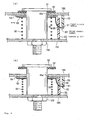
- Fig. 3 is a cross-sectional view of a steering wheel 100A equipped with an airbag system 1A with such a structure.
- Figs. 4(a) and 4(b) are enlarged views of the horn switch device in Fig. 3.
- Fig. 4(a) shows "an undepressed” state in which a module cover is not depressed
- Fig. 4(b) shows "a module-cover depressed state” in which the module cover is depressed to sound a horn.
- This airbag system 1A also includes a retainer 10A, an airbag 20 mounted to the retainer 10A with a ring 24, an inflator 30 for inflating the airbag 20, a module cover 40A that covers the folded airbag 20, a horn switch device 60, etc.
- the entire airbag system 1A constructs a retractable body.
- the retainer 10A of this embodiment also has a substantially rectangular main plate 11.
- the airbag 20 and the inflator 30 are mounted to the main plate 11, whose mounting structure is the same as that of the airbag system 1 in Fig. 1.
- An enclosure 15A stands upward in Fig. 3 (toward the occupant) from the outer rim of the main plate 11 of the retainer 10A.
- An extension 16A extends laterally (to the side of the airbag system 1A or in the direction perpendicular to the direction in which the airbag system 1A retracts (vertically in Fig. 3), ditto for the following) from the distal end of the enclosure 15A in the standing direction.
- the module cover 40A has a main surface 41 that faces the occupant and a leg 42A extending downward in Fig. 3 (in the direction opposite to the occupant) along the inner wall of the enclosure 15A from the back of the main surface 41.
- the leg 42A is fixed to the enclosure 15A with a fixing member (not shown) such as a rivet.
- airbag-system supporting pieces 104 stand from the steering wheel 100A along the outer wall of the enclosure 15A.
- the supporting pieces 104 are provided as many as the extensions 16A, and are disposed such that the respective ends face the extensions 16A from below.
- a facing part 105 that extends to the side of the airbag system 1A (in parallel with the direction in which the extension 16A extends) and faces the lower surface of the extension 16A.
- the facing part 105 constructs an unmoving body.
- a nut 106 for fixing a guide shaft is fixed.
- the extension 16A has an opening 45a' (see Fig. 4), through which the guide shaft 50 passes.
- the lower end of the guide shaft 50 is screwed into the nut 106 at the facing part 105 to be fixed to the facing part 105 and stands upward from the facing part 105.
- a flange 51 is provided as a stopper at the upper end of the guide shaft 50. Between the flange 51 and the extension 16A is interposed an electrically insulating washer 52 made of rubber or the like.
- a horn switch device 60 is disposed between the extension 16A and the facing part 105.
- the horn switch device 60 is substantially the same as that shown in Fig. 2.
- the overhang 45 in Fig. 2 is replaced with the extension 16A, and the extension 16 is replaced with the facing part 105.
- the pedestal 53 having the first contact member 61 projects from the lower surface of the extension 16A, as shown in Fig. 4.
- the ring 63 is disposed below the lower surface of the extension 16A via the flat washer 54, through the openings of which the 50 passes.
- a coil spring 90 is interposed between the ring 63 and the facing part 105 while having a reserve of energy.
- the washer 54 and the ring 63 are pushed against the extension 16A and held by the biasing force of the coil spring 90.
- the contacting body 55 of this embodiment rises from the upper surface of the facing part 105.
- the second contact member 62 is apart from the first contact member 61.
- the entire airbag system 1A is pushed downward. Along with that, the extension 16A and the first and second contact members 61 and 62 fall together. With the falling, the coil spring 90 is compressed.
- the facing part 105 is integrated with the steering wheel 100A, so that the facing part 105 is not displaced even if the module cover 40A is depressed. Also the guide shaft 50 fixed to the facing part 105 is not displaced.
- the second contact member 62 comes into contact with the lower rim of the window 56, so that the further falling of the second contact member 62 is stopped. Since the first contact member 61 continues falling thereafter, the contact members 61 and 62 come into contact with each other. Thus, the horn switch device 60 is turned on to sound the horn.
- the first and second contact members 61 and 62 and the extension 16A are pushed up by the repulsive force of the coil spring 90 to return to the state shown in Fig. 4(a). This opens the contact members 61 and 62 to stop sounding the horn. Along with that, the entire airbag system 1A returns to the initial position.
- both of the first and second contact members 61 and 62 are mounted to or supported by the airbag system 1A, so that they can be positioned easily and accurately. This reduces the difficulty in assembling the horn switch device 60 or the airbag system 1A.
Landscapes
- Engineering & Computer Science (AREA)
- Mechanical Engineering (AREA)
- Physics & Mathematics (AREA)
- Acoustics & Sound (AREA)
- Air Bags (AREA)
- Steering Controls (AREA)
- Push-Button Switches (AREA)
Abstract
Description
- The present invention relates to a horn switch, and in particular, it relates to a horn switch device provided in an airbag system and constructed such that, when depressed, a module cover is retracted to turn on a horn switch. The invention also relates to an airbag system and a steering wheel including the horn switch device.
- Driver-seat airbag systems mounted to car steering wheels are disclosed in which when the module covers of the airbag systems are depressed, horn switches are turned on to sound horns. JP-A-10-100832 (Patent Document 1) and JP-A-2001-114057 (Patent Document 2) describe airbag systems in which, when depressed, a module cover is retracted to turn on a horn switch.
- In the related-art horn switch devices, one of contact members is mounted to the module cover, and the other is mounted to a retainer. The separate contact members increase the difficulty in assembling work to position them with high accuracy.
- Accordingly, it is an object of the present invention to provide a horn switch device in which a pair of contact members is provided only on one of a retractable body such as a module cover and an unmoving body such as a retainer or a steering wheel, so that the contact members can easily be located, and an airbag system and a steering wheel including the horn switch device.
- A horn switch device according to Claim 1 includes a retractable body that is retracted by depression by an occupant; an unmoving body that faces the retractable body; a biasing member interposed between the retractable body and the unmoving body, for biasing the retractable body in the restoring direction; and a pair of contact members whose contacts come into or out of contact with each other by the movement of the retractable body. Both of the pair of contact members move together with the retractable body. The unmoving body has a contacting body that comes into contact with one of the contact members when the retractable body retracts, to stop the retraction of the contact member, thereby bringing the contacts into contact with each other.
- The horn switch device according to Claim 2 is characterized in that, in Claim 1, the retractable body is the module cover of an airbag system.
- The horn switch device according to Claim 3 is characterized in that, in Claim 2, the unmoving body is a member extending from the retainer of the airbag system.
- The horn switch device according to Claim 4 is characterized in that, in Claim 1, the retractable body is an airbag system.
- The horn switch device according to Claim 5 is characterized in that, in Claim 4, the unmoving body is a steering wheel or a member extending from the steering wheel.
- An airbag system according to Claim 6 includes a horn switch device, wherein the horn switch device is the horn switch device according to one of Claims 1 to 5.
- A steering wheel according to Claim 7 includes a horn switch, wherein the horn switch is the horn switch device according to one of Claims 1 to 5.
- A steering wheel according to Claim 8 is equipped with an airbag system including a horn switch device, wherein the airbag system is the airbag system according to Claim 6.
- In the horn switch device according to Claim 1, the contact members are apart from each other when the retractable body such as a module cover or an airbag system is in a restored position (undepressed state). When the retractable body is depressed, one of the contact members comes into contact with the contacting body to bring the contacts into contact with each other, thereby sounding the horn.
- In this horn switch device, the contact members are provided only to the retractable body. Accordingly, the contact members can easily be positioned, improving the workability in assembling the airbag system, the steering wheel, etc.
- In the invention, the retractable body may be either a module cover or an airbag system. When the retractable body is a module cover, the unmoving body is preferably a member extending from a retainer; when the retractable body is an airbag system, the unmoving member is preferably a steering wheel or a member extending from the steering wheel.
- Embodiments of the present invention will be specifically described hereinafter with reference to the drawings.
- Fig. 1 is a cross-sectional view of a steering wheel equipped with an airbag system including a horn switch device according to an embodiment;
- Fig. 2 is a cross-sectional view of the horn switch device in Fig. 1;
- Fig. 3 is a cross-sectional view of a steering wheel equipped with an airbag system including a horn switch device according to another embodiment; and
- Fig. 4 is a cross-sectional view of the horn switch device in Fig. 3.
- The airbag system 1 is a driver-seat airbag system disposed in the center (a base 101) of a
steering wheel 100. The airbag system 1 includes ametal retainer 10, anairbag 20 mounted to theretainer 10 with an airbag-fixing ring 24, aninflator 30 for inflating theairbag 20, a synthetic-resin module cover 40 that covers the foldedairbag 20, ahorn switch device 60, etc. - According to the embodiment, the module cover 40 constructs a retractable body. The
module cover 40 has a groove-like tear line 40a. When theairbag 20 is inflated by theinflator 30, themodule cover 40 is cleaved along thetear line 40a. - The
retainer 10 has a substantially rectangularmain plate 11. Themain plate 11 has anopening 12 for theinflator 30 to pass through. Around the opening 12 are provided through holes forstud bolts 25 standing from the airbag-fixing ring 24. - An
anchor piece 14 stands downward in the drawing (in the direction opposite to the occupant) from the outer rim of themain plate 11 of theretainer 10. Theanchor piece 14 is used to fix the airbag system 1 to thesteering wheel 100. Theanchor piece 14 has openings 14a for bolts or rivets to pass through. Thesteering wheel 100 has an airbag-system mounting piece 102 rising from thebase 101 thereof. Themounting piece 102 also has an opening 102a for a bolt or a rivet to pass through. - In mounting the airbag system 1 to the
steering wheel 100, theanchor piece 14 is placed on themounting piece 102, and they are joined with a bolt or arivet 103 through theopenings openings - An
enclosure 15 stands upward in Fig. 1 (toward the occupant) from the outer rim of themain plate 11 of theretainer 10. Anextension 16 extends laterally (to the side of the airbag system 1) from the distal end of theenclosure 15 in the standing direction. In this embodiment, theextension 16 constructs an unmoving body. - To the
extension 16 is fixed anut 17, to which the lower end of aguide shaft 50 is screwed. - The
airbag 20 has a structure in which the periphery of aninflator insertion hole 22 thereof is placed on the periphery of the inflator opening 12 of the retainermain plate 11, on which the airbag-fixing ring 24 is placed. Thestud bolts 25 are passed through the bolt insertion holes provided around theinflator insertion hole 22 of theairbag 20. Eachstud bolt 25 is then passed through a bolt insertion hole of theretainer 10. Thestud bolt 25 is then passed through a bolt insertion hole of aflange 31 of theinflator 30, on which anut 26 is tightened. Theairbag 20 and theinflator 30 are thus fixed to theretainer 10. - The
module cover 40 has amain surface 41 that faces the occupant and aleg 42 extending from the back of themain surface 41. Theleg 42 is molded integrally with themain surface 41 by injection molding of synthetic resin and has a substantially rectangular frame shape similar to theenclosure 15 of theretainer 10. Theperiphery 41a of themain surface 41 overhangs outward from theleg 42. - The
leg 42 mounts anoverhang 45. Theoverhang 45 extends outward in the direction perpendicular to the direction in which the module cover 40 retracts. Theoverhang 45 has an opening 45a for theguide shaft 50 to pass through. - As shown in Fig. 2, the lower end of the
guide shaft 50 is screwed into thenut 17 of theextension 16 to be fixed to theextension 16 and stands from theextension 16 toward the occupant. The guide shaft 50 projects upward relative to theoverhang 45 through the opening 45a and has aflange 51 at the upper end as a stopper. Between theflange 51 and theoverhang 45 is interposed awasher 52 made of an electrical insulation material such as rubber. - An electrically insulating
pedestal 53 extends downward from the lower end of theoverhang 45 in parallel with theguide shaft 50. A projectingfirst contact member 61 is provided at the lower end of thepedestal 53. - A
ring 63 is disposed under the lower surface of theoverhang 45 via aflat washer 54. Thewasher 54 and thering 63 are disposed coaxially, through which theguide shaft 50 passes. Acoil spring 90 is interposed between thering 63 and theextension 16 while having a reserve of energy. The biasing force of thecoil spring 90 pushes thewasher 54 and thering 63 against theoverhang 45. - A
second contact member 62 extends from thering 63. Thesecond contact member 62 extends toward theextension 16 in a downward slanting direction with increasing distance from thering 63. Thesecond contact member 62 curves to swell out toward theguide shaft 50 relative to the line that connects the distal end and the base end. - A contacting
body 55 rises from the upper surface of theextension 16 in parallel with theguide shaft 50. The contactingbody 55 is located between thepedestal 53 and theguide shaft 50. The contactingbody 55 has awindow 56 in the middle. Thesecond contact member 62 passes through thewindow 56 to extend to the position below thefirst contact member 61. - As shown in Fig. 2(a), before the
module cover 40 is depressed, thesecond contact member 62 is located a specified distance apart from the lower rim of thewindow 56. - The horn-sounding action of the
steering wheel 100 equipped with the airbag system 1 including thishorn switch device 60 will now be described. - As shown in Fig. 2(a), before the
module cover 40 is depressed, thesecond contact member 62 is apart from thefirst contact member 61. - When the
module cover 40 is depressed, theoverhang 45 is pushed down, so that the first andsecond contact members coil spring 90 is compressed. - The
extension 16 extends from theretainer 10 fixed to thesteering wheel 100, so that theextension 16 is not displaced even if themodule cover 40 is depressed. Also theguide shaft 50 fixed to theextension 16 is not displaced. - As the first and
second contact members second contact member 62 is brought into contact with the lower rim of thewindow 56, so that the further falling of thesecond contact member 62 is stopped. Since thefirst contact member 61 continues falling thereafter, thecontact members horn switch device 60 is turned on to sound the horn. - On release from the
module cover 40, the first andsecond contact members module cover 40 are pushed up by the repulsive force of thecoil spring 90 into the state shown in Fig. 2(a). Thecontact members - In this
horn switch device 60, as described above, both of the first andsecond contact members module cover 40, so that they can be positioned easily and accurately. This reduces the difficulty in assembling thehorn switch device 60 or the airbag system 1. - While the embodiment has a structure in which only the module cover is retracted by depression, the invention can also be applied to an airbag system in which the module cover and the retainer move vertically together. Fig. 3 is a cross-sectional view of a steering wheel 100A equipped with an airbag system 1A with such a structure. Figs. 4(a) and 4(b) are enlarged views of the horn switch device in Fig. 3. Fig. 4(a) shows "an undepressed" state in which a module cover is not depressed, and Fig. 4(b) shows "a module-cover depressed state" in which the module cover is depressed to sound a horn.
- This airbag system 1A also includes a
retainer 10A, anairbag 20 mounted to theretainer 10A with aring 24, aninflator 30 for inflating theairbag 20, amodule cover 40A that covers the foldedairbag 20, ahorn switch device 60, etc. According to this embodiment, the entire airbag system 1A constructs a retractable body. - The
retainer 10A of this embodiment also has a substantially rectangularmain plate 11. Theairbag 20 and the inflator 30 are mounted to themain plate 11, whose mounting structure is the same as that of the airbag system 1 in Fig. 1. - An
enclosure 15A stands upward in Fig. 3 (toward the occupant) from the outer rim of themain plate 11 of theretainer 10A. Anextension 16A extends laterally (to the side of the airbag system 1A or in the direction perpendicular to the direction in which the airbag system 1A retracts (vertically in Fig. 3), ditto for the following) from the distal end of theenclosure 15A in the standing direction. - The
module cover 40A has amain surface 41 that faces the occupant and aleg 42A extending downward in Fig. 3 (in the direction opposite to the occupant) along the inner wall of theenclosure 15A from the back of themain surface 41. Theleg 42A is fixed to theenclosure 15A with a fixing member (not shown) such as a rivet. - In this embodiment, airbag-
system supporting pieces 104 stand from the steering wheel 100A along the outer wall of theenclosure 15A. The supportingpieces 104 are provided as many as theextensions 16A, and are disposed such that the respective ends face theextensions 16A from below. At the end of each supportingpiece 104 is provided a facingpart 105 that extends to the side of the airbag system 1A (in parallel with the direction in which theextension 16A extends) and faces the lower surface of theextension 16A. In this embodiment, the facingpart 105 constructs an unmoving body. To the facingpart 105, anut 106 for fixing a guide shaft is fixed. - In this embodiment, the
extension 16A has anopening 45a' (see Fig. 4), through which theguide shaft 50 passes. The lower end of theguide shaft 50 is screwed into thenut 106 at the facingpart 105 to be fixed to the facingpart 105 and stands upward from the facingpart 105. Also in this embodiment, aflange 51 is provided as a stopper at the upper end of theguide shaft 50. Between theflange 51 and theextension 16A is interposed an electrically insulatingwasher 52 made of rubber or the like. - In this embodiment, a
horn switch device 60 is disposed between theextension 16A and the facingpart 105. Thehorn switch device 60 is substantially the same as that shown in Fig. 2. In this embodiment, theoverhang 45 in Fig. 2 is replaced with theextension 16A, and theextension 16 is replaced with the facingpart 105. - Specifically, in this embodiment, the
pedestal 53 having thefirst contact member 61 projects from the lower surface of theextension 16A, as shown in Fig. 4. Thering 63 is disposed below the lower surface of theextension 16A via theflat washer 54, through the openings of which the 50 passes. Acoil spring 90 is interposed between thering 63 and the facingpart 105 while having a reserve of energy. Thewasher 54 and thering 63 are pushed against theextension 16A and held by the biasing force of thecoil spring 90. The contactingbody 55 of this embodiment rises from the upper surface of the facingpart 105. - The other structure of this embodiment is the same as that of the embodiment of Figs. 1 and 2. The same numerals of Figs. 3 and 4 as those of Figs. 1 and 2 indicate the same components.
- The horn-sounding action of the steering wheel 100A equipped with the airbag system 1A having this
horn switch device 60 will be described. - As shown in Fig. 4(a), before the
module cover 40A is depressed, thesecond contact member 62 is apart from thefirst contact member 61. - When the
module cover 40A is depressed, the entire airbag system 1A is pushed downward. Along with that, theextension 16A and the first andsecond contact members coil spring 90 is compressed. - The facing
part 105 is integrated with the steering wheel 100A, so that the facingpart 105 is not displaced even if themodule cover 40A is depressed. Also theguide shaft 50 fixed to the facingpart 105 is not displaced. - As the first and
second contact members second contact member 62 comes into contact with the lower rim of thewindow 56, so that the further falling of thesecond contact member 62 is stopped. Since thefirst contact member 61 continues falling thereafter, thecontact members horn switch device 60 is turned on to sound the horn. - On release from the
module cover 40A, the first andsecond contact members extension 16A are pushed up by the repulsive force of thecoil spring 90 to return to the state shown in Fig. 4(a). This opens thecontact members - Also in this embodiment, both of the first and
second contact members horn switch device 60 or the airbag system 1A.
Claims (8)
- A horn switch device comprising:a retractable body that is retracted by depression by an occupant;an unmoving body that faces the retractable body;a biasing member interposed between the retractable body and the unmoving body, for biasing the retractable body in the restoring direction; anda pair of contact members whose contacts come into or out of contact with each other by the movement of the retractable body, whereinboth of the pair of contact members move together with the retractable body; andthe unmoving body has a contacting body that comes into contact with one of the contact members when the retractable body retracts, to stop the retraction of the contact member, thereby bringing the contacts into contact with each other.
- The horn switch device according to Claim 1, wherein the retractable body is the module cover of an airbag system.
- The horn switch device according to Claim 1 or 2, wherein the unmoving body is a member extending from the retainer of the airbag system.
- The horn switch device according to Claim 1, 2 or 3, wherein the retractable body is an airbag system.
- The horn switch device according to Claim 4, wherein the unmoving body is a steering wheel or a member extending from the steering wheel.
- An airbag system including a horn switch device, wherein the horn switch device is the horn switch device according to one of Claims 1 to 5.
- A steering wheel including a horn switch, wherein the horn switch is the horn switch device according to one of Claims 1 to 5.
- A steering wheel equipped with an airbag system including a horn switch device, wherein the airbag system is the airbag system according to Claim 6.
Applications Claiming Priority (3)
| Application Number | Priority Date | Filing Date | Title |
|---|---|---|---|
| JP2004366357 | 2004-12-17 | ||
| JP2005011774 | 2005-01-19 | ||
| JP2005183678A JP2006228699A (en) | 2004-12-17 | 2005-06-23 | Horn switch device, air bag device, and steering wheel |
Publications (1)
| Publication Number | Publication Date |
|---|---|
| EP1671854A1 true EP1671854A1 (en) | 2006-06-21 |
Family
ID=35759353
Family Applications (1)
| Application Number | Title | Priority Date | Filing Date |
|---|---|---|---|
| EP05026985A Withdrawn EP1671854A1 (en) | 2004-12-17 | 2005-12-09 | Horn switch device, airbag system, and steering wheel |
Country Status (3)
| Country | Link |
|---|---|
| US (1) | US7360786B2 (en) |
| EP (1) | EP1671854A1 (en) |
| JP (1) | JP2006228699A (en) |
Cited By (1)
| Publication number | Priority date | Publication date | Assignee | Title |
|---|---|---|---|---|
| WO2014124954A1 (en) * | 2013-02-15 | 2014-08-21 | Autoliv Development Ab | Device for damping vibrations of an airbag or an airbag apparatus |
Families Citing this family (9)
| Publication number | Priority date | Publication date | Assignee | Title |
|---|---|---|---|---|
| JP2006092921A (en) * | 2004-09-24 | 2006-04-06 | Takata Corp | Horn switch device, air-bag device and steering device |
| US8491003B2 (en) | 2010-02-23 | 2013-07-23 | Judco Manufacturing, Inc. | Airbag frame apparatus |
| US8939466B2 (en) | 2010-02-23 | 2015-01-27 | Judco Partnership, Llc | Airbag frame apparatus |
| JP2015189390A (en) * | 2014-03-28 | 2015-11-02 | 豊田合成株式会社 | steering wheel |
| DE102016124530A1 (en) | 2016-12-15 | 2018-06-21 | Trw Automotive Safety Systems Gmbh | Coupling device for vibratory mounting of a gas bag module to a vehicle steering wheel |
| US11718257B2 (en) | 2016-12-15 | 2023-08-08 | Zf Passive Safety Systems Us Inc | Coupling device for mounting an airbag module to be oscillating on a vehicle steering wheel |
| DE102017119886A1 (en) * | 2017-08-30 | 2019-02-28 | Trw Automotive Safety Systems Gmbh | SPRING ELEMENT FOR FASTENING A GASSACK MODULE TO A VEHICLE WHEEL AND A STEERING WHEEL ASSEMBLY WITH SUCH A SPRING ELEMENT |
| KR102729863B1 (en) * | 2018-11-16 | 2024-11-12 | 현대자동차주식회사 | Steering for vehicles |
| KR20240033489A (en) * | 2022-09-05 | 2024-03-12 | 현대자동차주식회사 | Steering wheel and damper unit of the steering wheel |
Citations (5)
| Publication number | Priority date | Publication date | Assignee | Title |
|---|---|---|---|---|
| FR1471447A (en) * | 1966-03-09 | 1967-03-03 | Flii Vitaloni | Push button switch |
| US5410114A (en) * | 1992-12-25 | 1995-04-25 | Toyoda Gosei Co., Ltd. | Steering wheel horn switch mechanism |
| US20020153714A1 (en) * | 2001-04-18 | 2002-10-24 | Martin Kreuzer | Assembly unit having an airbag module and a vehicle steering wheel |
| US20040046367A1 (en) * | 2002-09-09 | 2004-03-11 | Trw Automotive Safety Systems Gmbh | Airbag module and assembly of steering wheel and airbag module |
| EP1475270A2 (en) * | 2003-05-07 | 2004-11-10 | TRW Automotive Safety Systems GmbH | Assembly comprising a steering wheel and an airbag module |
Family Cites Families (29)
| Publication number | Priority date | Publication date | Assignee | Title |
|---|---|---|---|---|
| JPS56135349A (en) * | 1980-03-25 | 1981-10-22 | Nissan Motor Co Ltd | Switch device on steering wheel |
| JPH02139174U (en) * | 1989-04-24 | 1990-11-20 | ||
| US5627352A (en) * | 1994-09-28 | 1997-05-06 | Toyoda Gosei Co., Ltd. | Steering wheel |
| JPH08207783A (en) * | 1994-12-07 | 1996-08-13 | Toyoda Gosei Co Ltd | Steering wheel |
| US5650600A (en) * | 1995-06-01 | 1997-07-22 | Trw Inc. | Horn switch for air bag module |
| DE69725246T2 (en) * | 1996-08-06 | 2004-07-29 | Toyoda Gosei Co., Ltd., Haruhi | steering wheel |
| US6478330B2 (en) * | 1996-08-06 | 2002-11-12 | Toyoda Gosei Co., Ltd. | Steering wheel |
| JP3726101B2 (en) | 1996-09-30 | 2005-12-14 | オートリブ・ジャパン株式会社 | Driver airbag module |
| DE29805207U1 (en) * | 1998-03-23 | 1998-06-04 | TRW Automotive Safety Systems GmbH, 63743 Aschaffenburg | Steering wheel with an airbag |
| JPH11278280A (en) | 1998-03-26 | 1999-10-12 | Nippon Plast Co Ltd | Steering wheel |
| US6719323B2 (en) * | 1999-08-06 | 2004-04-13 | Honda Giken Kogyo Kabushiki Kaisha | Air bag apparatus and steering wheel |
| JP2001187576A (en) | 1999-12-28 | 2001-07-10 | T S Tec Kk | Horn switch mechanism for steering wheel |
| JP4581244B2 (en) * | 2000-01-14 | 2010-11-17 | タカタ株式会社 | Airbag device and steering wheel |
| JP2001199300A (en) | 2000-01-17 | 2001-07-24 | Hosei Brake Ind Ltd | Steering wheel structure |
| JP2001213326A (en) | 2000-01-31 | 2001-08-07 | Nippon Plast Co Ltd | Steering wheel |
| JP2001233159A (en) | 2000-02-18 | 2001-08-28 | Tokai Rika Co Ltd | Air bag device assembling structure |
| JP4538956B2 (en) * | 2000-03-17 | 2010-09-08 | タカタ株式会社 | Airbag device |
| JP2001278060A (en) | 2000-03-30 | 2001-10-10 | Nippon Plast Co Ltd | Horn device for steering wheel |
| JP2001277976A (en) | 2000-03-31 | 2001-10-10 | Nippon Plast Co Ltd | Vehicular air bag device |
| JP3942338B2 (en) * | 2000-05-12 | 2007-07-11 | 豊田合成株式会社 | Steering wheel horn switch |
| ITTO20010784A1 (en) * | 2001-08-03 | 2003-02-03 | Breed Automotive Tech | HORSE WARNING DEVICE FOR A VEHICLE STEERING WHEEL. |
| GB2390337A (en) * | 2002-07-02 | 2004-01-07 | Autoliv Dev | Steering wheel with airbag centrally and resiliently mounted |
| DE20216755U1 (en) * | 2002-10-30 | 2003-03-20 | TRW Automotive Safety Systems GmbH & Co. KG, 63743 Aschaffenburg | steering wheel |
| JP2004168284A (en) * | 2002-11-01 | 2004-06-17 | Takata Corp | Airbag device |
| JP2005038811A (en) * | 2003-06-30 | 2005-02-10 | Takata Corp | Horn switching device and air bag device |
| US7268309B2 (en) * | 2003-06-30 | 2007-09-11 | Takata Corporation | Horn switch gear and airbag system |
| US7159897B2 (en) * | 2003-07-21 | 2007-01-09 | Delphi Technologies, Inc. | Isolated ground for horn mechanism |
| JP2006044390A (en) * | 2004-08-02 | 2006-02-16 | Honda Motor Co Ltd | Switch case mounting structure |
| JP2007035609A (en) * | 2004-12-10 | 2007-02-08 | Takata Corp | Horn switch device, air bag device, and steering wheel |
-
2005
- 2005-06-23 JP JP2005183678A patent/JP2006228699A/en not_active Withdrawn
- 2005-11-21 US US11/282,728 patent/US7360786B2/en not_active Expired - Fee Related
- 2005-12-09 EP EP05026985A patent/EP1671854A1/en not_active Withdrawn
Patent Citations (5)
| Publication number | Priority date | Publication date | Assignee | Title |
|---|---|---|---|---|
| FR1471447A (en) * | 1966-03-09 | 1967-03-03 | Flii Vitaloni | Push button switch |
| US5410114A (en) * | 1992-12-25 | 1995-04-25 | Toyoda Gosei Co., Ltd. | Steering wheel horn switch mechanism |
| US20020153714A1 (en) * | 2001-04-18 | 2002-10-24 | Martin Kreuzer | Assembly unit having an airbag module and a vehicle steering wheel |
| US20040046367A1 (en) * | 2002-09-09 | 2004-03-11 | Trw Automotive Safety Systems Gmbh | Airbag module and assembly of steering wheel and airbag module |
| EP1475270A2 (en) * | 2003-05-07 | 2004-11-10 | TRW Automotive Safety Systems GmbH | Assembly comprising a steering wheel and an airbag module |
Cited By (4)
| Publication number | Priority date | Publication date | Assignee | Title |
|---|---|---|---|---|
| WO2014124954A1 (en) * | 2013-02-15 | 2014-08-21 | Autoliv Development Ab | Device for damping vibrations of an airbag or an airbag apparatus |
| CN105073507A (en) * | 2013-02-15 | 2015-11-18 | 奥托立夫开发公司 | Device for damping vibrations of an airbag or an airbag apparatus |
| US9561772B2 (en) | 2013-02-15 | 2017-02-07 | Autoliv Deveopment AB | Device for damping vibrations of an airbag or an airbag apparatus |
| CN105073507B (en) * | 2013-02-15 | 2017-12-01 | 奥托立夫开发公司 | Apparatus for damping vibrations of airbags or airbag arrangements |
Also Published As
| Publication number | Publication date |
|---|---|
| JP2006228699A (en) | 2006-08-31 |
| US7360786B2 (en) | 2008-04-22 |
| US20060131851A1 (en) | 2006-06-22 |
Similar Documents
| Publication | Publication Date | Title |
|---|---|---|
| EP1671853A1 (en) | Horn switch device, airbag system, and steering wheel | |
| US6688637B2 (en) | Airbag apparatus | |
| US7173202B2 (en) | Horn switch device, airbag system, and steering wheel | |
| EP0572125B1 (en) | Centre horn switch in driver side air bag module | |
| KR101685236B1 (en) | Air bag device | |
| US8336911B2 (en) | Safety arrangement and method for the production of such a safety arrangement | |
| US6719324B2 (en) | Horn contact apparatus and method | |
| EP1671854A1 (en) | Horn switch device, airbag system, and steering wheel | |
| US11548439B2 (en) | Vehicle horn control system | |
| JP2001260794A (en) | Air bag device | |
| EP1623886A2 (en) | Horn switch gear, airbag system, steering wheel and steering device | |
| US11034319B2 (en) | Air bag module | |
| US20090261560A1 (en) | Airbag device and steering wheel | |
| US6908102B2 (en) | Airbag apparatus | |
| US7422236B2 (en) | Apparatus and method for providing a horn contact mechanism | |
| JPH08318806A (en) | Airbag module for driver's seat | |
| JP3671490B2 (en) | Airbag device for driver's seat | |
| KR0158788B1 (en) | Steering wheel | |
| JP3665881B2 (en) | Driver airbag module | |
| JP3276508B2 (en) | Steering wheel | |
| JPH06270816A (en) | Steering wheel with various kinds of switch | |
| JPH09104311A (en) | Driver airbag module | |
| JP2006228697A (en) | Horn switch device, air bag device, and steering wheel | |
| KR100542590B1 (en) | Car horn | |
| JP2583387Y2 (en) | Steering wheel |
Legal Events
| Date | Code | Title | Description |
|---|---|---|---|
| PUAI | Public reference made under article 153(3) epc to a published international application that has entered the european phase |
Free format text: ORIGINAL CODE: 0009012 |
|
| AK | Designated contracting states |
Kind code of ref document: A1 Designated state(s): AT BE BG CH CY CZ DE DK EE ES FI FR GB GR HU IE IS IT LI LT LU LV MC NL PL PT RO SE SI SK TR |
|
| AX | Request for extension of the european patent |
Extension state: AL BA HR MK YU |
|
| 17P | Request for examination filed |
Effective date: 20061214 |
|
| 17Q | First examination report despatched |
Effective date: 20070112 |
|
| AKX | Designation fees paid |
Designated state(s): DE FR GB SE |
|
| STAA | Information on the status of an ep patent application or granted ep patent |
Free format text: STATUS: THE APPLICATION IS DEEMED TO BE WITHDRAWN |
|
| 18D | Application deemed to be withdrawn |
Effective date: 20071206 |