EP1670987B1 - Multilayer papermaker's fabric having pocket areas defined by a plane difference between at least two top layer weft yarns - Google Patents
Multilayer papermaker's fabric having pocket areas defined by a plane difference between at least two top layer weft yarns Download PDFInfo
- Publication number
- EP1670987B1 EP1670987B1 EP04780569A EP04780569A EP1670987B1 EP 1670987 B1 EP1670987 B1 EP 1670987B1 EP 04780569 A EP04780569 A EP 04780569A EP 04780569 A EP04780569 A EP 04780569A EP 1670987 B1 EP1670987 B1 EP 1670987B1
- Authority
- EP
- European Patent Office
- Prior art keywords
- fabric
- yarns
- papermaker
- weft
- top layer
- Prior art date
- Legal status (The legal status is an assumption and is not a legal conclusion. Google has not performed a legal analysis and makes no representation as to the accuracy of the status listed.)
- Expired - Lifetime
Links
- 239000004744 fabric Substances 0.000 title claims abstract description 150
- 239000011230 binding agent Substances 0.000 claims description 15
- 239000004952 Polyamide Substances 0.000 claims description 4
- 229920002647 polyamide Polymers 0.000 claims description 3
- 229920000728 polyester Polymers 0.000 claims description 3
- 239000007779 soft material Substances 0.000 claims description 2
- 238000009740 moulding (composite fabrication) Methods 0.000 description 77
- 239000010410 layer Substances 0.000 description 60
- 230000015572 biosynthetic process Effects 0.000 description 11
- 239000000835 fiber Substances 0.000 description 10
- XLYOFNOQVPJJNP-UHFFFAOYSA-N water Substances O XLYOFNOQVPJJNP-UHFFFAOYSA-N 0.000 description 8
- 230000000694 effects Effects 0.000 description 5
- 238000000034 method Methods 0.000 description 4
- 230000001965 increasing effect Effects 0.000 description 3
- 238000004519 manufacturing process Methods 0.000 description 3
- 239000000463 material Substances 0.000 description 3
- 238000000059 patterning Methods 0.000 description 3
- 239000002356 single layer Substances 0.000 description 3
- 239000002002 slurry Substances 0.000 description 3
- 238000007605 air drying Methods 0.000 description 2
- 238000001035 drying Methods 0.000 description 2
- 239000002759 woven fabric Substances 0.000 description 2
- 229920003043 Cellulose fiber Polymers 0.000 description 1
- 241000206607 Porphyra umbilicalis Species 0.000 description 1
- 230000002411 adverse Effects 0.000 description 1
- 238000010924 continuous production Methods 0.000 description 1
- 230000007812 deficiency Effects 0.000 description 1
- 238000000151 deposition Methods 0.000 description 1
- 239000006185 dispersion Substances 0.000 description 1
- 230000002708 enhancing effect Effects 0.000 description 1
- 238000001704 evaporation Methods 0.000 description 1
- 230000008020 evaporation Effects 0.000 description 1
- 230000001747 exhibiting effect Effects 0.000 description 1
- 230000001815 facial effect Effects 0.000 description 1
- 229920006122 polyamide resin Polymers 0.000 description 1
- 229920001225 polyester resin Polymers 0.000 description 1
- 239000004645 polyester resin Substances 0.000 description 1
- 239000002952 polymeric resin Substances 0.000 description 1
- 238000003825 pressing Methods 0.000 description 1
- 239000007787 solid Substances 0.000 description 1
- 239000000725 suspension Substances 0.000 description 1
- 229920003002 synthetic resin Polymers 0.000 description 1
- 238000012876 topography Methods 0.000 description 1
- 239000011800 void material Substances 0.000 description 1
- 238000009941 weaving Methods 0.000 description 1
Images


Classifications
-
- D—TEXTILES; PAPER
- D21—PAPER-MAKING; PRODUCTION OF CELLULOSE
- D21F—PAPER-MAKING MACHINES; METHODS OF PRODUCING PAPER THEREON
- D21F1/00—Wet end of machines for making continuous webs of paper
- D21F1/0027—Screen-cloths
- D21F1/0036—Multi-layer screen-cloths
- D21F1/0045—Triple layer fabrics
-
- D—TEXTILES; PAPER
- D21—PAPER-MAKING; PRODUCTION OF CELLULOSE
- D21F—PAPER-MAKING MACHINES; METHODS OF PRODUCING PAPER THEREON
- D21F1/00—Wet end of machines for making continuous webs of paper
-
- D—TEXTILES; PAPER
- D21—PAPER-MAKING; PRODUCTION OF CELLULOSE
- D21F—PAPER-MAKING MACHINES; METHODS OF PRODUCING PAPER THEREON
- D21F11/00—Processes for making continuous lengths of paper, or of cardboard, or of wet web for fibre board production, on paper-making machines
-
- D—TEXTILES; PAPER
- D21—PAPER-MAKING; PRODUCTION OF CELLULOSE
- D21F—PAPER-MAKING MACHINES; METHODS OF PRODUCING PAPER THEREON
- D21F11/00—Processes for making continuous lengths of paper, or of cardboard, or of wet web for fibre board production, on paper-making machines
- D21F11/006—Making patterned paper
-
- D—TEXTILES; PAPER
- D21—PAPER-MAKING; PRODUCTION OF CELLULOSE
- D21F—PAPER-MAKING MACHINES; METHODS OF PRODUCING PAPER THEREON
- D21F11/00—Processes for making continuous lengths of paper, or of cardboard, or of wet web for fibre board production, on paper-making machines
- D21F11/14—Making cellulose wadding, filter or blotting paper
-
- Y—GENERAL TAGGING OF NEW TECHNOLOGICAL DEVELOPMENTS; GENERAL TAGGING OF CROSS-SECTIONAL TECHNOLOGIES SPANNING OVER SEVERAL SECTIONS OF THE IPC; TECHNICAL SUBJECTS COVERED BY FORMER USPC CROSS-REFERENCE ART COLLECTIONS [XRACs] AND DIGESTS
- Y10—TECHNICAL SUBJECTS COVERED BY FORMER USPC
- Y10S—TECHNICAL SUBJECTS COVERED BY FORMER USPC CROSS-REFERENCE ART COLLECTIONS [XRACs] AND DIGESTS
- Y10S162/00—Paper making and fiber liberation
- Y10S162/903—Paper forming member, e.g. fourdrinier, sheet forming member
Definitions
- the present invention relates to the papermaking arts. More specifically, the present invention relates to forming fabrics for the forming section of a paper machine.
- a cellulosic fibrous web is formed by depositing a fibrous slurry, that is, an aqueous dispersion of cellulose fibers, onto a moving forming fabric in the forming section of a paper machine. A large amount of water is drained from the slurry through the forming fabric, leaving the cellulosic fibrous web on the surface of the forming fabric.
- a fibrous slurry that is, an aqueous dispersion of cellulose fibers
- the newly formed cellulosic fibrous web proceeds from the forming section to a press section, which includes a series of press nips.
- the cellulosic fibrous web passes through the press nips supported by a press fabric, or, as is often the case, between two such press fabrics.
- the press nips the cellulosic fibrous web is subjected to compressive forces which squeeze water therefrom, and which adhere the cellulosic fibers in the web to one another to turn the cellulosic fibrous web into a paper sheet.
- the water is accepted by the press fabric or fabrics and, ideally, does not return to the paper sheet.
- the paper sheet finally proceeds to a dryer section, which includes at least one series of rotatable dryer drums or cylinders, which are internally heated by steam.
- the newly formed paper sheet is directed in a serpentine path sequentially around each in the series of drums by a dryer fabric, which holds the paper sheet closely against the surfaces of the drums.
- the heated drums reduce the water content of the paper sheet to a desirable level through evaporation.
- the forming, press and dryer fabrics all take the form of endless loops on the paper machine and function in the manner of conveyors. It should further be appreciated that paper manufacture is a continuous process which proceeds at considerable speeds. That is to say, the fibrous slurry is continuously deposited onto the forming fabric in the forming section, while a newly manufactured paper sheet is continuously wound onto rolls after it exits from the dryer section.
- the properties of absorbency, strength, softness, and aesthetic appearance are important for many products when used for their intended purpose, particularly when the fibrous cellulosic products are facial or toilet tissue, paper towels, sanitary napkins or diapers.
- An alternative process employs a through air drying (TAD) unit either replacing the press fabric above with another woven fabric which transfers the sheet from the forming fabric to the through air drying fabric. It is this fabric which transfers the sheet to a TAD cylinder where hot air is blown through the wet cellulosic sheet, simultaneously drying the sheet and enhancing sheet bulk and softness.
- TAD through air drying
- Woven fabrics take many different forms. For example, they may be woven endless, or flat woven and subsequently rendered into endless form with a seam.
- the present invention relates specifically to the forming fabrics used in the forming section.
- Forming fabrics play a critical role during the paper manufacturing process.
- One of their functions, as implied above, is to form and convey the paper product being manufactured to the press section.
- forming fabrics also need to address water removal and sheet formation issues. That is, forming fabrics are designed to allow water to pass through (i.e. control the rate of drainage) while at the same time prevent fiber an other solids from passing through with the water. If drainage occurs too rapidly or too slowly, the sheet quality and machine efficiency suffers. To control drainage, the space within the forming fabric for the water to drain, commonly referred to as void volume, must be properly designed.
- Contemporary forming fabrics are produced in a wide variety of styles designed to meet the requirements of the paper machines on which they are installed for the paper grades being manufactured. Generally, they comprise a base fabric woven from monofilament and may be single-layered or multi-layered. The yarns are typically extruded from any one of several synthetic polymeric resins, such as polyamide and polyester resins, used for this purpose by those of ordinary skill in the paper machine clothing arts.
- the design of forming fabrics additionally involves a compromise between the desired fiber support and fabric stability.
- a fine mesh fabric may provide the desired paper surface and fiber support properties, but such design may lack the desired stability resulting in a short fabric life.
- coarse mesh fabrics provide stability and long life at the expense of fiber support and the potential for marking.
- multi-layer fabrics were developed. For example, in double and triple layer fabrics, the forming side is designed for support while the wear side is designed for stability.
- fabrics are created by weaving, and having a weave pattern which repeats in both the warp or machine direction (MD) and the weft or cross-machine direction (CD). It will also be appreciated that the resulting fabric must be uniform in appearance; that is there are no abrupt changes in the weave pattern to result in undesirable characteristics in the formed paper sheet. Due to the repeating nature of the weave patterns, a common fabric deficiency is a characteristic diagonal pattern in the fabric. In addition, any pattern marking imparted to the formed tissue will impact the characteristics of the paper.
- a fabric will often be constructed so that the top surface exhibits plane differences between strands.
- a plane difference is typically measured as the difference in height between two adjacent weft (cross direction) strands in the plane of the forming surface.
- Bulk, cross directional tensile, absorbency, and softness are particularly important characteristics when producing sheets of tissue, napkin, and towel paper.
- tissue forming fabrics preferably exhibit plane differences in the forming side.
- U.S. Patent 5,456,293 shows a single layer TAD fabric wherein the MD yarns are interwoven to produce a zigzag effect.
- the pattern has an array of pockets extending diagonally in alternating fashion across its width. Although the ⁇ 293 pattern does distribute these pockets, it is preferable to minimize the effects of any discernible pocket patterning.
- US 5544678 discloses a fabric comprising a top layer and a bottom layer of CD wefts and a system of MD warps interwoven therewith.
- the present invention is a multi-layer tissue forming fabric having different diameter, size, or shape weft strands to produce a plane difference on the forming side.
- the present invention provides a solution to the problems of providing a fabric pattern having a plane difference while maintaining good sheet fiber support and fabric stability properties.
- the present invention is a multi-layer forming fabric, although it may find application in the forming, pressing and drying sections of a paper machine.
- the present invention is a multi-layer fabric having a plane difference in the forming surface while maintaining good sheet fiber support and fabric stability properties.
- the fabric uses at least two different diameter, size, or shape weft strands positioned in the same contour in the forming surface to create a forming side plane difference in the tissue forming fabric. This plane difference in the forming surface generates bulk, cross directional tensile, absorbency, and softness in a sheet of tissue paper formed by the fabric.
- a first embodiment of the invention is a multi-layer forming fabric for use in producing tissue, napkin, and towel paper.
- the fabric comprises a top layer of cross-machine direction (CD) wefts, a bottom layer of CD wefts, and a system of machine-direction (MD) yarns interwoven with the top and bottom layers of CD wefts.
- the top layer has at least two different diameter, size, or shapes of weft yarns that are positioned at the same contour in the layer to produce a plane difference in the forming surface of the fabric. This plane difference in the forming surface generates bulk, cross directional tensile, absorbency, and softness in a sheet of tissue paper formed by the fabric.
- the top layer of CD yarns forms the forming side of the fabric and the bottom layer of CD yarns forms the wear side of the fabric.
- the top layer produces a forming surface impression that significantly reduces the typical problems caused by pocket patterning.
- each MD yarn weaves in the top layer over a small diameter CD weft yarn, under an adjacent large diameter CD weft yarn and the next small CD weft yarn, and over the next large CD weft yarn before crossing to weave in pattern with the bottom laver.
- the CD weft yarns in the top layer may be vertically stacked with the CD weft yarns in the bottom layer.
- the present invention may also include a middle layer of CD weft yarns between the top layer and bottom layer and being interwoven with the system of MD yarns.
- these middle layer CD weft yarns may be vertically stacked with the CD weft yarns in the bottom layer to form a TSS (triple stacked shute double layer) fabric.
- TSS triple stacked shute double layer
- Another embodiment of the invention is a papermaker's fabric comprising a top layer of weft yarns having at least two different diameters, sizes, or shapes positioned at the same contour and interwoven with a system of warp yarns, and a bottom layer of weft yarns interwoven with the system of warp yarns.
- the weft yarns and warp yarns define pocket areas in the surface of the top layer.
- the top layer has at least three levels produced by plane differences between the largest diameter weft yarn and the warp yarns. These levels define pocket depths corresponding to the pocket areas.
- Still another embodiment of the invention is a papermaker's fabric comprising a top layer of weft yarns having at least three different diameters, sizes, or shapes positioned at the same contour and interwoven with a system of warp yarns; a bottom layer of weft yarns interwoven with the system of warp yarns; and binder weft yarns for binding the top layer and bottom layer together to form the fabric.
- the weft yarns which have the larger two diameters and the warp yarns define macro-pocket areas in the surface of the top layer.
- the weft yarns which have the smallest diameter, the binder weft yarns, and the warp yarns define micro-pocket areas in the surface of the top layer.
- the top layer has at least three levels produced by plane differences between the largest diameter weft yarns and the warp yarns. These levels define pocket depths corresponding to the macro-pocket areas and micro-pocket areas.
- the MD yarns and CD wefts are preferably monofilament yarns.
- at least some of the MD yarns and some of the CD weft yarns are preferably one of polyester, polyamide or other polymeric materials known to those skilled in the art of forming fabrics
- the MD yarns and CD wefts may have a circular cross-sectional shape, a rectangular cross-sectional shape or a non-round cross-sectional shape.
- the yarn is of a non-round cross section, for example rectangular, it will usually be woven such that the larger dimension (MD/CD aspect ratio in the CD dimension is larger) is always oriented the same, that is, the yarn is not twisted.
- the yarn is allowed to twist as it is woven and the twist adds a random appearance to the fabric. In other words, the twisted yarns produce a textured fabric which results in a random marking pattern.
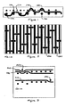
- FIG. 1 is a schematic cross-sectional view in the CD of an example fabric pattern in accordance with the teachings of the present invention.
- the present invention is a multi-layer tissue forming fabric constructed so that the top forming surface has topographical differences measured as a plane difference between two top weft yarns.
- the plane difference the difference in height between two adjacent weft yarns —must be greater than zero.
- the present invention uses at least two different diameter CD weft yarns 100, 110 and positions them on the same contour in the forming surface to create the forming side plane difference in the tissue forming fabric.
- the plane difference in the forming surface generates bulk, cross directional tensile, absorbency, and softness in a sheet of tissue, napkin, or towel paper.
- the present invention is preferably a double layer or triple stacked shute (TSS) double layer fabric.
- TSS triple stacked shute
- the present invention is applicable to any multi-layer fabric style including double layer, double layer support (stacked) shute (DLSS
- each MD yarn 120 passes over a smaller weft 140 in the forming side, under the adjacent larger weft yarn and the next smaller weft yarn, and over the next larger weft yarn 150 before crossing to the bottom layer where it weaves in pattern with the bottom layer CD weft yarns 130.
- FIG 2 is a schematic forming side (top) view of the fabric shown in Figure 1 . Note the machine direction is horizontal. As in Figure 1 , each MD yarn passes over a smaller weft yarn 240 in the forming side, under the adjacent larger weft yarn and the next smaller weft yarn, and over the next larger weft yarn 250 before crossing to the bottom layer.
- the MD yarns are staggered as shown and repeat in pattern every eighth yarn.
- the pattern shown is merely one embodiment of the invention. The invention should not be construed as being limited to this example pattern.
- Figure 3 shows two schematic cross-sectional views in the MD of a fabric pattern in accordance with the teachings of the present invention.
- the top view shows the larger diameter top CD weft yarn 300, which is vertically stacked over the bottom layer CD weft yarn 330.
- a single MD yarn 350 passes over both the CD weft yarns at one location. This knuckle 350 corresponds to knuckle 150 in Figure 1 and knuckle 250 in Figure 2 .
- the bottom view in Figure 3 shows the smaller diameter top CD weft yarn 310.
- a single MD yarn 340 passes over the small CD weft yarn 310, at one location. This knuckle 340 corresponds to knuckle 140 in Figure 1 and knuckle 240 in Figure 2 .
- the invention should not be construed as being limited to the example pattern shown.
- Figure 4 shows an exaggerated schematic cross-sectional view in the CD of the top layer of an example fabric pattern in accordance with the teachings of: 4a) the prior art and 4b) the present invention.
- View 4b illustrates the formation of a tissue paper 460 formed by the plane difference in the forming surface of the fabric produced by two different sized CD weft yarns 400, 410 positioned in the same contour.
- the two different sized CD weft yarns 400,410 are positioned in different contours such that they align in the same plane to produce a uniform forming surface.
- a plane difference in the forming surface generates bulk, cross directional tensile, absorbency, and softness in a sheet of tissue, napkin, or towel paper.
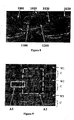
- Figure 5 is a forming side view of a fabric woven in accordance with the teachings of the present invention and a forming side impression made from the fabric Importantly, the imprint of the fabric shows defined pockets minimizing diagonal patterning. This is an advantage of the present invention's fabric pattern over prior art tissue forming fabrics.
- the present invention may also be characterized by pocket areas defined by the yarn pattern in the textured forming surface of the fabric. By aligning different size weft yarns at the same contour in the fabric layer, and by choosing the proper weave pattern, the pocket depth, area and volume can be maximized.
- more than two yarn diameters, sizes, or shapes may be used to define pockets having multiple depth levels and sizes. These pockets may alternatively be described as multiple frames in the forming surface having varying sizes and depths.
- a multi-level pocket depth and size results in a less defined macro surface.
- This embodiment of the present invention incorporates multiple levels of (weft induced) texture with the goal of generating variable levels and sizes of micro-pockets in the forming surface of the fabric which may contribute to the overall bulk of a formed tissue, napkin, or towel sheet. This also enhances the absorptive capacity while maintaining CD tensile and softness in the tissue sheet of paper.
- the paperside surface of the tissue forming fabric is constructed in such a way that the top surface has topographical differences of three or more levels (as measured by plane differences between each top weft yarn and the adjacent warp yarns).
- the (square area of the) pockets are defined by choosing a reference warp yarn and a reference weft yarn and finding the furthest adjacent weft yarn that defines a pocket area.
- FIG. 6 is a forming side view showing defined pocket areas in accordance with the teachings of the present invention.
- rectangles have been superimposed to outline the pocket areas.
- a reference warp yarn knuckle C1 is first selected. From this reference knuckle C1, the warp yarn is traced in the machine direction (up and down in the picture) until the first adjacent weft yarn float is reached (points C2 and.C2a). Then, moving in the cross machine direction, this weft yarn is traced until another warp yarn knuckle appears (points C3 and C3a) in the direction which yields the larger pocket area.
- the longest non-broken weft yarn float moves from left to right and from point C2a the longest non-broken weft yarn float moves right to left.
- the border of the pockets then move along the longest non-broken weft yarn until the next adjacent warp yarn knuckle is reached, i.e. points C3 and C3a. From points C3 and C3a, the borders of the pockets are traced in the opposite direction of travel between points C1 and C2 (or C1 and C2a), until the nearest adjacent weft yarn float is reached (points C4 and C4a).
- the pockets are enclosed by forming a line connecting points C4 or C4a with reference point C1. As shown, the top pocket area is predominantly defined by weft yarns 610, 620 and 630.
- the pocket depth may be optimized.
- the combination of the pocket area and pocket depth defines the pocket volume. Due to the inherent woven nature of the fabric, each defined pocket will have one or more warp yarns located at specific depths below the plane of the fabric surface. It is preferable to have the predominant warp yarns in the pocket at the same plane and to have these predominant warp yarns be as deep as possible beneath the surface of the fabric. This provides the pocket with a large volume.
- Figure 7 is a forming side view showing the predominant warp yarns within a pocket. As shown, the superimposed rectangle corresponds to the border of a pocket area. Within this pocket are two predominant warp yarns 710 and 720. By optimizing the pocket volume (by controlling the pocket size and depth), the properties of the formed tissue, napkin, or towel sheets can be enhanced.
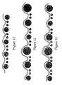
- Figure 10 shows the formation of a tissue paper across the different sized CD yarns of a fabric pattern corresponding to those shown in Figures 6 and 7 .
- This view is analogous to view 4b of Figure 4 and can be contrasted with the prior art shown in view 4a.
- Figure 8 is a cross-sectional view in the MD of a fabric wherein the predominant warp yarns 1100 and 1200 are in the same contour a predetermined distance below the surface of the fabric.
- the reference knuckle 1001 for this pocket area is similar to the reference knuckle C1 shown in Figure 6 .
- Surface weft yarn float 1010 is the long non-broken weft yarn float on the forming surface.
- a significantly large weft yarn 1010 may also distort the overall weave pattern.
- One method of avoiding or minimizing such distortion is to vary the properties of the yarns used.
- polymeric monofilaments may be produced from hard or soft materials. A soft weft material will flex around the warps more easily, thus providing a higher knuckle than a harder weft material. In this case, a softer monofilament can be used to further optimize the pocket depth without distorting the weave pattern.
- micro and macro pockets can be defined by the choice of weave pattern. In such a case, both the micro and macro pockets can act to enhance the surface topography and formed tissue sheet characteristics.
- Figure 9 is a forming side view of another embodiment of the present invention having defined micro and macro pocket areas. In this embodiment, differing diameter wefts are used to create both micro and macro topographical imprints.
- the present fabric includes forming weft yarns W1, W2, and W3; binder yarn groups C; micro pockets A1; and macro pockets A2.
- the forming weft yarns W1, W2 and W3 preferably have different diameters while the yarns in the binder groups C have the same diameter as forming weft yarn W2.
- This arrangement of forming and binder weft yarns produce micro pockets A1 which are similar to the pocket area described in Figure 6 .
- This arrangement also produces macro pockets A2 having a significantly larger surface area than the micro pockets. Due to this surface area difference, the macro pockets will effect the final sheet surface differently than the micro pockets.
- the micro pockets are small enough to impact the small length fibers used in sheet formation while the macro pockets may impact the longer fibers used in sheet formation. Unlike the micro pockets, it is the plane difference between the largest diameter or size weft yarn and the smallest diameter or size weft yarn that determines the depth of the macro pockets. Also note that each macro pocket may contain several micro pockets. This feature acts to blend the effects of each pocket type.
- Figures 11 and 12 show the formation of a tissue paper across the different sized CD yarns of two exemplary fabric patterns, each corresponding to the fabrics shown in Figures 8 and 9 . Again, these figures are analogous to view 4b of Figure 4 and can be compared with the prior art shown in view 4a.
- the present multi-layered fabric can be a double layer, double layer support shute, triple layer with conventional CD binder, triple layer with paired CD binders, triple layer with conventional warp binder, triple layer with paired warp binders, and any other suitable type of multi-layer fabric weave patterns.
- the top layer and bottom layer of each fabric may be bound together by binder weft yarns, binder warp yarns, or integral warp or weft binders.
- the fabric according to the present invention preferably comprises only monofilament yarns.
- the yarns may be polyester, polyamide or other polymeric monofilament.
- the CD and MD yarns may have a circular cross-sectional shape with one or more different diameters. Further, in addition to a circular cross-sectional shape, one or more of the yarns may have other cross-sectional shapes such as a rectangular cross-sectional shape or a non-round cross-sectional shape.
Landscapes
- Woven Fabrics (AREA)
- Paper (AREA)
- Sanitary Thin Papers (AREA)
Abstract
Description
- The present invention relates to the papermaking arts. More specifically, the present invention relates to forming fabrics for the forming section of a paper machine.
- During the papermaking process, a cellulosic fibrous web is formed by depositing a fibrous slurry, that is, an aqueous dispersion of cellulose fibers, onto a moving forming fabric in the forming section of a paper machine. A large amount of water is drained from the slurry through the forming fabric, leaving the cellulosic fibrous web on the surface of the forming fabric.
- The newly formed cellulosic fibrous web proceeds from the forming section to a press section, which includes a series of press nips. The cellulosic fibrous web passes through the press nips supported by a press fabric, or, as is often the case, between two such press fabrics. In the press nips, the cellulosic fibrous web is subjected to compressive forces which squeeze water therefrom, and which adhere the cellulosic fibers in the web to one another to turn the cellulosic fibrous web into a paper sheet. The water is accepted by the press fabric or fabrics and, ideally, does not return to the paper sheet.
- The paper sheet finally proceeds to a dryer section, which includes at least one series of rotatable dryer drums or cylinders, which are internally heated by steam. The newly formed paper sheet is directed in a serpentine path sequentially around each in the series of drums by a dryer fabric, which holds the paper sheet closely against the surfaces of the drums. The heated drums reduce the water content of the paper sheet to a desirable level through evaporation.
- It should be appreciated that the forming, press and dryer fabrics all take the form of endless loops on the paper machine and function in the manner of conveyors. It should further be appreciated that paper manufacture is a continuous process which proceeds at considerable speeds. That is to say, the fibrous slurry is continuously deposited onto the forming fabric in the forming section, while a newly manufactured paper sheet is continuously wound onto rolls after it exits from the dryer section.
- The properties of absorbency, strength, softness, and aesthetic appearance are important for many products when used for their intended purpose, particularly when the fibrous cellulosic products are facial or toilet tissue, paper towels, sanitary napkins or diapers.
- These products can be produced using a variety of processes. Conventional manufacturing machines include a delivery of the suspension of cellulosic fiber onto one or between two forming fabrics. This partially dewatered sheet is then transferred to a press fabric, which dewaters the sheet further as it transfers the sheet to the surface of a large Yankee dryer. The fully dried sheet is either creped or not as it is removed from the Yankee surface and wound onto rolls for further processing.
- An alternative process employs a through air drying (TAD) unit either replacing the press fabric above with another woven fabric which transfers the sheet from the forming fabric to the through air drying fabric. It is this fabric which transfers the sheet to a TAD cylinder where hot air is blown through the wet cellulosic sheet, simultaneously drying the sheet and enhancing sheet bulk and softness.
- Woven fabrics take many different forms. For example, they may be woven endless, or flat woven and subsequently rendered into endless form with a seam.
- The present invention relates specifically to the forming fabrics used in the forming section. Forming fabrics play a critical role during the paper manufacturing process. One of their functions, as implied above, is to form and convey the paper product being manufactured to the press section.
- However, forming fabrics also need to address water removal and sheet formation issues. That is, forming fabrics are designed to allow water to pass through (i.e. control the rate of drainage) while at the same time prevent fiber an other solids from passing through with the water. If drainage occurs too rapidly or too slowly, the sheet quality and machine efficiency suffers. To control drainage, the space within the forming fabric for the water to drain, commonly referred to as void volume, must be properly designed.
- Contemporary forming fabrics are produced in a wide variety of styles designed to meet the requirements of the paper machines on which they are installed for the paper grades being manufactured. Generally, they comprise a base fabric woven from monofilament and may be single-layered or multi-layered. The yarns are typically extruded from any one of several synthetic polymeric resins, such as polyamide and polyester resins, used for this purpose by those of ordinary skill in the paper machine clothing arts.
- The design of forming fabrics additionally involves a compromise between the desired fiber support and fabric stability. A fine mesh fabric may provide the desired paper surface and fiber support properties, but such design may lack the desired stability resulting in a short fabric life. By contrast, coarse mesh fabrics provide stability and long life at the expense of fiber support and the potential for marking. To minimize the design tradeoff and optimize both support and stability, multi-layer fabrics were developed. For example, in double and triple layer fabrics, the forming side is designed for support while the wear side is designed for stability.
- Those skilled in the art will appreciate that fabrics are created by weaving, and having a weave pattern which repeats in both the warp or machine direction (MD) and the weft or cross-machine direction (CD). It will also be appreciated that the resulting fabric must be uniform in appearance; that is there are no abrupt changes in the weave pattern to result in undesirable characteristics in the formed paper sheet. Due to the repeating nature of the weave patterns, a common fabric deficiency is a characteristic diagonal pattern in the fabric. In addition, any pattern marking imparted to the formed tissue will impact the characteristics of the paper.
- To generate bulk, cross directional tensile, absorbency, and softness in a sheet of paper, a fabric will often be constructed so that the top surface exhibits plane differences between strands. For example, a plane difference is typically measured as the difference in height between two adjacent weft (cross direction) strands in the plane of the forming surface. Bulk, cross directional tensile, absorbency, and softness are particularly important characteristics when producing sheets of tissue, napkin, and towel paper. Hence, tissue forming fabrics preferably exhibit plane differences in the forming side.
- One attempt to provide a plane difference is shown in
U.S. Patent 5,456,293 . The '293 patent shows a single layer TAD fabric wherein the MD yarns are interwoven to produce a zigzag effect. However, as stated in the '293 patent's abstract, the pattern has an array of pockets extending diagonally in alternating fashion across its width. Although the `293 pattern does distribute these pockets, it is preferable to minimize the effects of any discernible pocket patterning. - Additionally, several other patents disclose single layer fabrics having plane differences; e.g.
U.S. Patent 5,806,569 ,U.S. Patent 5,839,478 , andU.S. Patent 5,853,547 . While all of these patents describe fabrics exhibiting a plane difference in the forming side, their single layer designs do not allow for the optimized balance between support and stability that multi-layer fabrics can provide. -
US 5544678 discloses a fabric comprising a top layer and a bottom layer of CD wefts and a system of MD warps interwoven therewith. - Therefore, a need exists for a tissue forming fabric having a plane difference in the forming side to generate bulk, cross directional tensile, absorbency, and softness in the tissue paper while minimizing the adverse effects of a strongly defined diagonal pocket pattern.
- A further need exists for such a fabric to provide more cross-directional stability and stiffness to prevent cross directional fabric shrinkage, improve sheet formation and appearance, and potentially increase life.
- The present invention is a multi-layer tissue forming fabric having different diameter, size, or shape weft strands to produce a plane difference on the forming side. The present invention provides a solution to the problems of providing a fabric pattern having a plane difference while maintaining good sheet fiber support and fabric stability properties.
- Accordingly, the present invention is a multi-layer forming fabric, although it may find application in the forming, pressing and drying sections of a paper machine.
- The present invention is a multi-layer fabric having a plane difference in the forming surface while maintaining good sheet fiber support and fabric stability properties. To obtain these characteristics, the fabric uses at least two different diameter, size, or shape weft strands positioned in the same contour in the forming surface to create a forming side plane difference in the tissue forming fabric. This plane difference in the forming surface generates bulk, cross directional tensile, absorbency, and softness in a sheet of tissue paper formed by the fabric.
- A first embodiment of the invention is a multi-layer forming fabric for use in producing tissue, napkin, and towel paper. The fabric comprises a top layer of cross-machine direction (CD) wefts, a bottom layer of CD wefts, and a system of machine-direction (MD) yarns interwoven with the top and bottom layers of CD wefts. The top layer has at least two different diameter, size, or shapes of weft yarns that are positioned at the same contour in the layer to produce a plane difference in the forming surface of the fabric. This plane difference in the forming surface generates bulk, cross directional tensile, absorbency, and softness in a sheet of tissue paper formed by the fabric. The top layer of CD yarns forms the forming side of the fabric and the bottom layer of CD yarns forms the wear side of the fabric. The top layer produces a forming surface impression that significantly reduces the typical problems caused by pocket patterning.
- Preferably, in this embodiment of the fabric, each MD yarn weaves in the top layer over a small diameter CD weft yarn, under an adjacent large diameter CD weft yarn and the next small CD weft yarn, and over the next large CD weft yarn before crossing to weave in pattern with the bottom laver. The CD weft yarns in the top layer may be vertically stacked with the CD weft yarns in the bottom layer.
- The present invention may also include a middle layer of CD weft yarns between the top layer and bottom layer and being interwoven with the system of MD yarns. Alternatively, these middle layer CD weft yarns may be vertically stacked with the CD weft yarns in the bottom layer to form a TSS (triple stacked shute double layer) fabric. Note the terms "shute" and "weft" are interchangeable in this context.
- Another embodiment of the invention is a papermaker's fabric comprising a top layer of weft yarns having at least two different diameters, sizes, or shapes positioned at the same contour and interwoven with a system of warp yarns, and a bottom layer of weft yarns interwoven with the system of warp yarns. The weft yarns and warp yarns define pocket areas in the surface of the top layer. The top layer has at least three levels produced by plane differences between the largest diameter weft yarn and the warp yarns. These levels define pocket depths corresponding to the pocket areas.
- Still another embodiment of the invention is a papermaker's fabric comprising a top layer of weft yarns having at least three different diameters, sizes, or shapes positioned at the same contour and interwoven with a system of warp yarns; a bottom layer of weft yarns interwoven with the system of warp yarns; and binder weft yarns for binding the top layer and bottom layer together to form the fabric. The weft yarns which have the larger two diameters and the warp yarns define macro-pocket areas in the surface of the top layer. The weft yarns which have the smallest diameter, the binder weft yarns, and the warp yarns define micro-pocket areas in the surface of the top layer. The top layer has at least three levels produced by plane differences between the largest diameter weft yarns and the warp yarns. These levels define pocket depths corresponding to the macro-pocket areas and micro-pocket areas.
- Other aspects of the present invention include that the MD yarns and CD wefts are preferably monofilament yarns. Also, at least some of the MD yarns and some of the CD weft yarns are preferably one of polyester, polyamide or other polymeric materials known to those skilled in the art of forming fabrics The MD yarns and CD wefts may have a circular cross-sectional shape, a rectangular cross-sectional shape or a non-round cross-sectional shape. When the yarn is of a non-round cross section, for example rectangular, it will usually be woven such that the larger dimension (MD/CD aspect ratio in the CD dimension is larger) is always oriented the same, that is, the yarn is not twisted. In one aspect of the invention, the yarn is allowed to twist as it is woven and the twist adds a random appearance to the fabric. In other words, the twisted yarns produce a textured fabric which results in a random marking pattern.
- The present invention will now be described in more complete detail with frequent reference being made to the drawing figures, which are identified below.
- For a more complete understanding of the invention, reference is made to the following description and accompanying drawings, in which:
-
Figure 1 is a schematic cross-sectional view in the CD of a fabric pattern in accordance with the teachings of the present invention; -
Figure 2 is a schematic forming side (top) view of a fabric woven in accordance with the teachings of the present invention; -
Figure 3 shows two schematic cross-sectional views in the MD of a fabric pattern in accordance with the teachings of the present invention; -
Figure 4 shows the formation of a tissue paper across the different sized CD yarns of a fabric pattern in accordance with the teachings of: a) the prior art and b) the present invention; -
Figure 5 is a forming side view and a forming side impression of a fabric woven in accordance with the teachings of the present invention; -
Figure 6 is a forming side view showing defined pocket areas in accordance with the teachings of the present invention; -
Figure 7 is a forming side view showing the predominant warp yarns within a pocket area in accordance with the teachings of the present invention; -
Figure 8 is a cross-sectional view in the MD of a fabric in accordance with the teachings of the present invention; -
Figure 9 is a forming side view showing defined micro and macro pocket areas in accordance with the teachings of the present invention; -
Figure 10 shows the formation of a tissue paper across the different sized CD yarns of a fabric pattern corresponding to those shown inFigures 6 and 7 ; -
Figure 11 shows the formation of a tissue paper across the different sized CD yarns of a fabric pattern corresponding to those shown inFigures 8 and 9 ; and -
Figure 12 shows the formation of a tissue paper across the different sized CD yarns of another fabric pattern corresponding to those shown inFigures 8 and 9 . -
Figure 1 is a schematic cross-sectional view in the CD of an example fabric pattern in accordance with the teachings of the present invention. As shown, the present invention is a multi-layer tissue forming fabric constructed so that the top forming surface has topographical differences measured as a plane difference between two top weft yarns. The plane difference—the difference in height between two adjacent weft yarns —must be greater than zero. The present invention uses at least two different diameterCD weft yarns - In the preferred embodiment, shown in
Figure 1 , eachMD yarn 120 passes over asmaller weft 140 in the forming side, under the adjacent larger weft yarn and the next smaller weft yarn, and over the nextlarger weft yarn 150 before crossing to the bottom layer where it weaves in pattern with the bottom layerCD weft yarns 130. -
Figure 2 is a schematic forming side (top) view of the fabric shown inFigure 1 . Note the machine direction is horizontal. As inFigure 1 , each MD yarn passes over asmaller weft yarn 240 in the forming side, under the adjacent larger weft yarn and the next smaller weft yarn, and over the nextlarger weft yarn 250 before crossing to the bottom layer. The MD yarns are staggered as shown and repeat in pattern every eighth yarn. The pattern shown is merely one embodiment of the invention. The invention should not be construed as being limited to this example pattern. -
Figure 3 shows two schematic cross-sectional views in the MD of a fabric pattern in accordance with the teachings of the present invention. The top view shows the larger diameter topCD weft yarn 300, which is vertically stacked over the bottom layerCD weft yarn 330. In one complete pattern, asingle MD yarn 350 passes over both the CD weft yarns at one location. Thisknuckle 350 corresponds to knuckle 150 inFigure 1 andknuckle 250 inFigure 2 . The bottom view inFigure 3 shows the smaller diameter top CD weft yarn 310. In one complete pattern, asingle MD yarn 340 passes over the small CD weft yarn 310, at one location. Thisknuckle 340 corresponds to knuckle 140 inFigure 1 andknuckle 240 inFigure 2 . Again, the invention should not be construed as being limited to the example pattern shown. -
Figure 4 shows an exaggerated schematic cross-sectional view in the CD of the top layer of an example fabric pattern in accordance with the teachings of: 4a) the prior art and 4b) the present invention.View 4b illustrates the formation of atissue paper 460 formed by the plane difference in the forming surface of the fabric produced by two different sizedCD weft yarns prior art view 4a, the two different sized CD weft yarns 400,410 are positioned in different contours such that they align in the same plane to produce a uniform forming surface. As discussed previously, a plane difference in the forming surface generates bulk, cross directional tensile, absorbency, and softness in a sheet of tissue, napkin, or towel paper. -
Figure 5 is a forming side view of a fabric woven in accordance with the teachings of the present invention and a forming side impression made from the fabric Importantly, the imprint of the fabric shows defined pockets minimizing diagonal patterning. This is an advantage of the present invention's fabric pattern over prior art tissue forming fabrics. - The present invention may also be characterized by pocket areas defined by the yarn pattern in the textured forming surface of the fabric. By aligning different size weft yarns at the same contour in the fabric layer, and by choosing the proper weave pattern, the pocket depth, area and volume can be maximized. In addition, more than two yarn diameters, sizes, or shapes may be used to define pockets having multiple depth levels and sizes. These pockets may alternatively be described as multiple frames in the forming surface having varying sizes and depths.
- A multi-level pocket depth and size results in a less defined macro surface. This embodiment of the present invention incorporates multiple levels of (weft induced) texture with the goal of generating variable levels and sizes of micro-pockets in the forming surface of the fabric which may contribute to the overall bulk of a formed tissue, napkin, or towel sheet. This also enhances the absorptive capacity while maintaining CD tensile and softness in the tissue sheet of paper.
- In another embodiment of the invention, the paperside surface of the tissue forming fabric is constructed in such a way that the top surface has topographical differences of three or more levels (as measured by plane differences between each top weft yarn and the adjacent warp yarns). The (square area of the) pockets are defined by choosing a reference warp yarn and a reference weft yarn and finding the furthest adjacent weft yarn that defines a pocket area.
-
Figure 6 is a forming side view showing defined pocket areas in accordance with the teachings of the present invention. InFigure 6 , rectangles have been superimposed to outline the pocket areas. To define the boundaries of the pocket areas, a reference warp yarn knuckle C1 is first selected. From this reference knuckle C1, the warp yarn is traced in the machine direction (up and down in the picture) until the first adjacent weft yarn float is reached (points C2 and.C2a). Then, moving in the cross machine direction, this weft yarn is traced until another warp yarn knuckle appears (points C3 and C3a) in the direction which yields the larger pocket area. Hence, from point C2 the longest non-broken weft yarn float moves from left to right and from point C2a the longest non-broken weft yarn float moves right to left. The border of the pockets then move along the longest non-broken weft yarn until the next adjacent warp yarn knuckle is reached, i.e. points C3 and C3a. From points C3 and C3a, the borders of the pockets are traced in the opposite direction of travel between points C1 and C2 (or C1 and C2a), until the nearest adjacent weft yarn float is reached (points C4 and C4a). The pockets are enclosed by forming a line connecting points C4 or C4a with reference point C1. As shown, the top pocket area is predominantly defined byweft yarns - In addition to the surface area of the pocket, the pocket depth may be optimized. The combination of the pocket area and pocket depth defines the pocket volume. Due to the inherent woven nature of the fabric, each defined pocket will have one or more warp yarns located at specific depths below the plane of the fabric surface. It is preferable to have the predominant warp yarns in the pocket at the same plane and to have these predominant warp yarns be as deep as possible beneath the surface of the fabric. This provides the pocket with a large volume.
-
Figure 7 is a forming side view showing the predominant warp yarns within a pocket. As shown, the superimposed rectangle corresponds to the border of a pocket area. Within this pocket are twopredominant warp yarns -
Figure 10 shows the formation of a tissue paper across the different sized CD yarns of a fabric pattern corresponding to those shown inFigures 6 and 7 . This view is analogous to view 4b ofFigure 4 and can be contrasted with the prior art shown inview 4a. -
Figure 8 is a cross-sectional view in the MD of a fabric wherein thepredominant warp yarns reference knuckle 1001 for this pocket area is similar to the reference knuckle C1 shown inFigure 6 . Surfaceweft yarn float 1010 is the long non-broken weft yarn float on the forming surface. By increasing the diameter ofweft yarn 1010, the vertical distance between the top of the weft yarn and the bottom of the pocket can be increased. However, if the diameter ofweft yarn 1010 is increased too much, the thickness of the weft yarn begins to reduce the area of the pocket; thereby offsetting any gains from the pocket depth. - A significantly
large weft yarn 1010 may also distort the overall weave pattern. One method of avoiding or minimizing such distortion is to vary the properties of the yarns used. For example, polymeric monofilaments may be produced from hard or soft materials. A soft weft material will flex around the warps more easily, thus providing a higher knuckle than a harder weft material. In this case, a softer monofilament can be used to further optimize the pocket depth without distorting the weave pattern. - Another aspect of the present invention is that micro and macro pockets can be defined by the choice of weave pattern. In such a case, both the micro and macro pockets can act to enhance the surface topography and formed tissue sheet characteristics.
Figure 9 is a forming side view of another embodiment of the present invention having defined micro and macro pocket areas. In this embodiment, differing diameter wefts are used to create both micro and macro topographical imprints. - As shown in
Figure 9 , the present fabric includes forming weft yarns W1, W2, and W3; binder yarn groups C; micro pockets A1; and macro pockets A2. The forming weft yarns W1, W2 and W3 preferably have different diameters while the yarns in the binder groups C have the same diameter as forming weft yarn W2. This arrangement of forming and binder weft yarns produce micro pockets A1 which are similar to the pocket area described inFigure 6 . This arrangement also produces macro pockets A2 having a significantly larger surface area than the micro pockets. Due to this surface area difference, the macro pockets will effect the final sheet surface differently than the micro pockets. For example, the micro pockets are small enough to impact the small length fibers used in sheet formation while the macro pockets may impact the longer fibers used in sheet formation. Unlike the micro pockets, it is the plane difference between the largest diameter or size weft yarn and the smallest diameter or size weft yarn that determines the depth of the macro pockets. Also note that each macro pocket may contain several micro pockets. This feature acts to blend the effects of each pocket type. -
Figures 11 and 12 show the formation of a tissue paper across the different sized CD yarns of two exemplary fabric patterns, each corresponding to the fabrics shown inFigures 8 and 9 . Again, these figures are analogous to view 4b ofFigure 4 and can be compared with the prior art shown inview 4a. - As mentioned above, although the examples shown in the figures are triple layer fabrics, the invention is not limited as such. As will be appreciated by one skilled in the art, the present multi-layered fabric can be a double layer, double layer support shute, triple layer with conventional CD binder, triple layer with paired CD binders, triple layer with conventional warp binder, triple layer with paired warp binders, and any other suitable type of multi-layer fabric weave patterns.
- Further, in the present forming fabrics, the top layer and bottom layer of each fabric may be bound together by binder weft yarns, binder warp yarns, or integral warp or weft binders.
- The fabric according to the present invention preferably comprises only monofilament yarns. Specifically, the yarns may be polyester, polyamide or other polymeric monofilament. The CD and MD yarns may have a circular cross-sectional shape with one or more different diameters. Further, in addition to a circular cross-sectional shape, one or more of the yarns may have other cross-sectional shapes such as a rectangular cross-sectional shape or a non-round cross-sectional shape.
Claims (21)
- A papermaker's fabric comprising:a top layer of cross-machine direction (CD) weft yarns (100, 110, 300, 310, 400, 410);a bottom layer of CD weft yarns (130, 330); anda system of machine-direction (MD) warp yarns (120, 340, 350) interwoven with the top and bottom layers of CD weft yarns (100, 110, 300), 310, 400, 410; 130, 330);characterized by the fact that the top layer comprises at least two different diameter, size, or shape weft yarns (100, 110, 300, 310, 400, 410) in a same contour to produce a plane difference in the forming surface of the fabric, such that the top layer produces a forming surface impression with a preferred pocket marking pattern, andby the fact that said top layer cross-machine direction (CD) weft yarns (100, 110, 300, 310, 400, 410) form floats longer than those of machine-direction (MD) warp yarns (120, 340,350) on the forming surface of the fabric.
- The papermaker's fabric according to claim 1, wherein the top layer of CD weft yarns (100, 110, 300, 310, 400, 410) forms a forming side of the fabric and the bottom layer of CD weft yarns (130, 330) forms a wear side of the fabric.
- The papermaker's fabric according to one of the previous claims, wherein the plane difference in the top layer generates bulk, cross directional tensile, absorbency, and softness in a sheet of paper formed by the fabric.
- The papermaker's fabric according to one of the previous claims, wherein each MD yarn (120)) weaves in the top layer over a small diameter CD weft, yarn (140), under an adjacent large diameter CD weft yarn and the next small diameter CD weft yarn, and over the next large diameter CD weft yarn (150) before crossing to weave in pattern with the bottom layer.
- The papermaker's fabric according to once of the previous claims, wherein the fabric is a double layer or double layer support shute fabric.
- The papermaker's fabric according to one of the previous claims, further comprising a middle layer of CD weft yarns between the top layer and bottom layer and being interwoven with the system of MD yarns (120, 340, 350).
- The papermaker's fabric according to one of the previous claims, wherein the at least two different diameter, size, or shape weft yarns (100, 110, 300, 310, 400, 410) alternate in the top layer.
- The papermaker's fabric according to claim 6, wherein the CD weft yarns in the middle layer are vertically stacked with the CD well yarns (130, 330) in the bottom layer.
- The papermaker's fabric according to claim 8, wherein the fabric is a triple stacked shute (TSS) fabric.
- The papermaker's fabric according to claim 1, wherein
the top layer has at least three levels produced by plane differences between a largest diameter, size, or shape weft yarn (100, 110, 300, 310, 400, 410) and the warp yarns (120, 340, 350); the levels defining pocket depths corresponding to pocket areas defined by the weft and warp yarns in the surface of the top layer. - The papermaker's fabric according to claim 10, wherein it comprises,
a top layer comprised of weft yarns (100, 110, 300, 310, 400, 410) of at least three different diameters, sizes, or shapes in a same contour interwoven with the system of warp yarns (120, 340, 350); and
binder weft yarns, hinder warp yarns, or integral warp or weft binders for binding the top layer and bottom layer together to form the fabric;
the weft yarns having the larger two diameters, sizes, or shapes and the warp yarns (120, 340, 350) defining macro-pocket areas in the surface of the top layer;
the weft yarns having the smallest diameter, the binder weft yarns, and the warp yarns (120, 340, 350) defining micro-pocket areas in the surface of the top layer;
said levels defining pocket depths corresponding to the macro-pocket areas and micro-pocket areas. - The papermaker's fabric according to claim 10 or 11, wherein the top layer forms a forming side of the fabric and the bottom layer forms a wear side, of the fabric.
- The papermaker's fabric according to one of claims 10 to 12, wherein the pocket areas and corresponding pocket depths in the top layer generales bulk, cross directional tensile, absorbency, and softness in a sheet of paper formed by the fabric.
- The papermaker's fabric according to one of claims 10 to 13, wherein each pocket area includes at least two predominant warp yarns (710, 720; 1100, 1200) at the same level.
- The papermaker's fabric according to one of claims 10 to 14, further comprising a middle layer of weft yarns between the top layer and bottom layer and being interwoven with the system of warp yarns (120, 340, 350).
- The papermaker's fabric according to one of the previous claims, wherein the fabric is a forming fabric for producing tissue, napkin, and towel paper.
- The papermaker's fabric according to one of the previous claims, wherein the wen yarns (100, 110, 300, 310, 400, 410; 130, 330) and warp yarns (120, 340, 350) are monofilaments.
- The papermaker's fabric according to one of the previous claims, wherein the weft yarns (100, 110, 300, 310, 400, 410; 130, 330) and/or warp yarns (120, 340, 350) are one of polyester yarns, polyamide yarns, or other polymeric yarns.
- The papermaker's fabric according to one of previous the claims, wherein at least some of the yarns (100, 110, 300, 310, 400, 410; 130, 330; 120, 340, 350) are one of hard or soft material yarns.
- The papermaker's fabric according to one of previous the claims, wherein the weft yarns (100, 110, 300, 310, 400, 410; 130, 330) and warp yarns (120, 340, 350) have a circular cross-sectional shape, a rectangular cross-sectioned shape or a non-round cross-sectional shape.
- The papermaker's fabric according to claim 20, wherein the rectangular cross-sectional shape yarns or non-round cross-sectional shape yarns are twisted.
Applications Claiming Priority (2)
| Application Number | Priority Date | Filing Date | Title |
|---|---|---|---|
| US10/659,962 US7300554B2 (en) | 2003-09-11 | 2003-09-11 | Textured surface of a tissue forming fabric to generate bulk, cross directional tensile, absorbency, and softness in a sheet of paper |
| PCT/US2004/025758 WO2005035867A1 (en) | 2003-09-11 | 2004-08-10 | Multilayer papermaker’s fabric having pocket areas defined by a plane difference between at least two top layer weft yarns |
Publications (2)
| Publication Number | Publication Date |
|---|---|
| EP1670987A1 EP1670987A1 (en) | 2006-06-21 |
| EP1670987B1 true EP1670987B1 (en) | 2012-01-11 |
Family
ID=34375773
Family Applications (1)
| Application Number | Title | Priority Date | Filing Date |
|---|---|---|---|
| EP04780569A Expired - Lifetime EP1670987B1 (en) | 2003-09-11 | 2004-08-10 | Multilayer papermaker's fabric having pocket areas defined by a plane difference between at least two top layer weft yarns |
Country Status (16)
| Country | Link |
|---|---|
| US (1) | US7300554B2 (en) |
| EP (1) | EP1670987B1 (en) |
| JP (1) | JP4465358B2 (en) |
| KR (1) | KR101097745B1 (en) |
| CN (1) | CN1849423B (en) |
| AT (1) | ATE541084T1 (en) |
| AU (1) | AU2004280561A1 (en) |
| BR (1) | BRPI0413946A (en) |
| CA (1) | CA2538108C (en) |
| ES (1) | ES2376762T3 (en) |
| NO (1) | NO20061617L (en) |
| PT (1) | PT1670987E (en) |
| RU (1) | RU2349694C2 (en) |
| TW (1) | TW200519246A (en) |
| WO (1) | WO2005035867A1 (en) |
| ZA (1) | ZA200602049B (en) |
Cited By (1)
| Publication number | Priority date | Publication date | Assignee | Title |
|---|---|---|---|---|
| DE102014219225A1 (en) * | 2014-09-24 | 2015-12-17 | Voith Patent Gmbh | conveyor belt |
Families Citing this family (40)
| Publication number | Priority date | Publication date | Assignee | Title |
|---|---|---|---|---|
| US7300543B2 (en) * | 2003-12-23 | 2007-11-27 | Kimberly-Clark Worldwide, Inc. | Tissue products having high durability and a deep discontinuous pocket structure |
| US7585395B2 (en) | 2004-01-30 | 2009-09-08 | Voith Patent Gmbh | Structured forming fabric |
| CA2605626C (en) * | 2005-04-20 | 2014-06-17 | Albany International Corp. | Through-air-drying fabric |
| US7059361B1 (en) | 2005-04-28 | 2006-06-13 | Albany International Corp. | Stable forming fabric with high fiber support |
| EP1877609A4 (en) * | 2005-05-05 | 2014-09-10 | Astenjohnson Inc | Bulk enhancing forming fabrics |
| US7395840B2 (en) * | 2005-05-26 | 2008-07-08 | Nippon Filcon Co. Ltd. | Industrial single-layer fabric having concave-convex surface |
| MX2008011578A (en) * | 2006-03-10 | 2008-11-26 | Astenjohnson Inc | Double layer papermakers fabric with pockets for bulk enhancement. |
| US7815768B2 (en) * | 2006-04-19 | 2010-10-19 | Albany International Corp. | Multi-layer woven creping fabric |
| DE102006022235A1 (en) * | 2006-05-12 | 2007-11-15 | Voith Patent Gmbh | Papermakers dryer |
| US7617846B2 (en) * | 2006-07-25 | 2009-11-17 | Albany International Corp. | Industrial fabric, and method of making thereof |
| US7743795B2 (en) | 2006-12-22 | 2010-06-29 | Voith Patent Gmbh | Forming fabric having binding weft yarns |
| US7604025B2 (en) | 2006-12-22 | 2009-10-20 | Voith Patent Gmbh | Forming fabric having offset binding warps |
| US7879195B2 (en) | 2007-09-06 | 2011-02-01 | Voith Patent Gmbh | Structured forming fabric and method |
| US7879193B2 (en) | 2007-09-06 | 2011-02-01 | Voith Patent Gmbh | Structured forming fabric and method |
| US7879194B2 (en) | 2007-09-06 | 2011-02-01 | Voith Patent Gmbh | Structured forming fabric and method |
| CN101849051B (en) * | 2007-09-25 | 2012-07-18 | 阿斯顿约翰逊公司 | Papermaker's fabric to develop caliper and topography in paper products |
| US7861747B2 (en) | 2008-02-19 | 2011-01-04 | Voith Patent Gmbh | Forming fabric having exchanging and/or binding warp yarns |
| US7878224B2 (en) | 2008-02-19 | 2011-02-01 | Voith Patent Gmbh | Forming fabric having binding warp yarns |
| US8002950B2 (en) | 2008-06-11 | 2011-08-23 | Voith Patent Gmbh | Structured fabric for papermaking and method |
| US20100186921A1 (en) | 2008-07-03 | 2010-07-29 | Quigley Scott D | Structured forming fabric, papermaking machine and method |
| US7993493B2 (en) | 2008-07-03 | 2011-08-09 | Voith Patent Gmbh | Structured forming fabric, papermaking machine and method |
| US8328990B2 (en) | 2008-07-03 | 2012-12-11 | Voith Patent Gmbh | Structured forming fabric, papermaking machine and method |
| US8038847B2 (en) | 2008-07-03 | 2011-10-18 | Voith Patent Gmbh | Structured forming fabric, papermaking machine and method |
| US8114254B2 (en) | 2008-07-30 | 2012-02-14 | Voith Patent Gmbh | Structured forming fabric, papermaking machine, and method |
| US20110152164A1 (en) * | 2009-12-21 | 2011-06-23 | Kenneth Bradley Close | Wet Wipe Having Improved Cleaning Capabilities |
| US8622095B2 (en) | 2011-02-02 | 2014-01-07 | Voith Patent Gmbh | Structured fabric for use in a papermaking machine and the fibrous web produced thereon |
| KR101908146B1 (en) * | 2011-04-11 | 2018-12-10 | 닛폰 휘루콘 가부시키가이샤 | Multilayer weave for nonwoven fabric |
| US9422666B2 (en) | 2011-09-27 | 2016-08-23 | Astenjohnson, Inc. | Ten-shed semi-duplex through-air dryer fabric |
| CA2773501A1 (en) | 2012-04-02 | 2013-10-02 | Derek Chaplin | Single layer through-air dryer fabrics |
| US20130309439A1 (en) | 2012-05-21 | 2013-11-21 | Kimberly-Clark Worldwide, Inc. | Fibrous Nonwoven Web with Uniform, Directionally-Oriented Projections and a Process and Apparatus for Making the Same |
| US9062416B2 (en) | 2012-11-13 | 2015-06-23 | Georgia-Pacific Consumer Products Lp | Apparatus, system, and process for determining characteristics of a surface of a papermaking fabric |
| US9382663B2 (en) | 2012-11-13 | 2016-07-05 | Georgia-Pacific Consumer Products Lp | Apparatus, system, and process for determining characteristics of a surface of a papermaking fabric |
| JP6457952B2 (en) | 2013-02-04 | 2019-01-23 | フェデラル−モーグル・パワートレイン・リミテッド・ライアビリティ・カンパニーFederal−Mogul Powertrain Llc | Wrapped woven sleeve and method for producing the same |
| CN105723029B (en) * | 2013-11-12 | 2017-12-01 | 佐治亚-太平洋消费产品有限合伙公司 | For the method for the feature for determining fabric |
| US9963831B2 (en) * | 2015-06-08 | 2018-05-08 | Gpcp Ip Holdings Llc | Soft absorbent sheets, structuring fabrics for making soft absorbent sheets, and methods of making soft absorbent sheets |
| US10138601B2 (en) | 2015-06-08 | 2018-11-27 | Gpcp Ip Holdings Llc | Soft absorbent sheets, structuring fabrics for making soft absorbent sheets, and methods of making soft absorbent sheets |
| US9879376B2 (en) | 2015-08-10 | 2018-01-30 | Voith Patent Gmbh | Structured forming fabric for a papermaking machine, and papermaking machine |
| JP6755097B2 (en) * | 2016-01-22 | 2020-09-16 | 日本フイルコン株式会社 | Industrial textiles |
| US10563353B2 (en) | 2016-12-30 | 2020-02-18 | Kimberly-Clark Worldwide, Inc. | Papermaking fabric including textured contacting surface |
| KR102720476B1 (en) * | 2017-09-29 | 2024-10-23 | 킴벌리-클라크 월드와이드, 인크. | Woven papermaking fabrics having machine and cross-machine oriented surface patterns |
Citations (2)
| Publication number | Priority date | Publication date | Assignee | Title |
|---|---|---|---|---|
| EP0263482A1 (en) * | 1986-10-07 | 1988-04-13 | Hermann Wangner GmbH & Co. KG | Fabric for the wet end of a paper-making machine |
| US6253796B1 (en) * | 2000-07-28 | 2001-07-03 | Weavexx Corporation | Papermaker's forming fabric |
Family Cites Families (18)
| Publication number | Priority date | Publication date | Assignee | Title |
|---|---|---|---|---|
| US1616222A (en) * | 1922-05-18 | 1927-02-01 | American Writing Paper Company | Fourdrinier-wire screen |
| FR2346489A1 (en) * | 1976-04-02 | 1977-10-28 | Martel Catala Et Cie Sa Ets | IMPROVEMENTS IN CANVAS FOR PAPER MACHINES AND THEIR MANUFACTURING PROCESSES |
| DE3713510A1 (en) * | 1987-04-22 | 1988-11-10 | Oberdorfer Fa F | PAPER MACHINE SCREEN FROM A DOUBLE-LAYER FABRIC |
| US5025839A (en) | 1990-03-29 | 1991-06-25 | Asten Group, Inc. | Two-ply papermakers forming fabric with zig-zagging MD yarns |
| FR2716522B3 (en) | 1994-02-22 | 1996-01-12 | Mr Ind | Cold formable composite duct and shape memory duct. |
| US5454405A (en) * | 1994-06-02 | 1995-10-03 | Albany International Corp. | Triple layer papermaking fabric including top and bottom weft yarns interwoven with a warp yarn system |
| US5456293A (en) | 1994-08-01 | 1995-10-10 | Wangner Systems Corporation | Woven papermaking fabric with diagonally arranged pockets and troughs |
| US5503196A (en) * | 1994-12-07 | 1996-04-02 | Albany International Corp. | Papermakers fabric having a system of machine-direction yarns residing interior of the fabric surfaces |
| US5817213A (en) * | 1995-02-13 | 1998-10-06 | Wangner Systems Corporation | Paper product formed from embossing fabric |
| US5544678A (en) | 1995-04-14 | 1996-08-13 | Jwi Ltd. | Composite forming fabric woven with an Nx2N machine side layer |
| US5853547A (en) * | 1996-02-29 | 1998-12-29 | Asten, Inc. | Papermaking fabric, process for producing high bulk products and the products produced thereby |
| AU1980797A (en) | 1996-04-04 | 1997-10-29 | Asten, Inc. | A multiplanar single layer forming fabric |
| WO1997038159A1 (en) * | 1996-04-04 | 1997-10-16 | Asten, Inc. | Papermaking fabric for increasing bulk in the paper sheet |
| US5937914A (en) | 1997-02-20 | 1999-08-17 | Weavexx Corporation | Papermaker's fabric with auxiliary yarns |
| US6112774A (en) | 1998-06-02 | 2000-09-05 | Weavexx Corporation | Double layer papermaker's forming fabric with reduced twinning. |
| DE19917832C2 (en) | 1999-04-20 | 2001-09-13 | Sca Hygiene Prod Gmbh | Paper machine clothing and tissue paper made with it |
| US6123116A (en) | 1999-10-21 | 2000-09-26 | Weavexx Corporation | Low caliper mechanically stable multi-layer papermaker's fabrics with paired machine side cross machine direction yarns |
| FI110798B (en) | 2001-10-23 | 2003-03-31 | Tamfelt Oyj Abp | The drying wire |
-
2003
- 2003-09-11 US US10/659,962 patent/US7300554B2/en not_active Expired - Fee Related
-
2004
- 2004-08-10 EP EP04780569A patent/EP1670987B1/en not_active Expired - Lifetime
- 2004-08-10 ZA ZA200602049A patent/ZA200602049B/en unknown
- 2004-08-10 CA CA2538108A patent/CA2538108C/en not_active Expired - Fee Related
- 2004-08-10 WO PCT/US2004/025758 patent/WO2005035867A1/en active Application Filing
- 2004-08-10 ES ES04780569T patent/ES2376762T3/en not_active Expired - Lifetime
- 2004-08-10 AU AU2004280561A patent/AU2004280561A1/en not_active Abandoned
- 2004-08-10 CN CN2004800261364A patent/CN1849423B/en not_active Expired - Fee Related
- 2004-08-10 JP JP2006526086A patent/JP4465358B2/en not_active Expired - Fee Related
- 2004-08-10 BR BRPI0413946-1A patent/BRPI0413946A/en not_active Application Discontinuation
- 2004-08-10 RU RU2006107576/12A patent/RU2349694C2/en not_active IP Right Cessation
- 2004-08-10 PT PT04780569T patent/PT1670987E/en unknown
- 2004-08-10 AT AT04780569T patent/ATE541084T1/en active
- 2004-08-19 TW TW093124964A patent/TW200519246A/en unknown
-
2006
- 2006-03-09 KR KR1020067004838A patent/KR101097745B1/en not_active IP Right Cessation
- 2006-04-10 NO NO20061617A patent/NO20061617L/en not_active Application Discontinuation
Patent Citations (2)
| Publication number | Priority date | Publication date | Assignee | Title |
|---|---|---|---|---|
| EP0263482A1 (en) * | 1986-10-07 | 1988-04-13 | Hermann Wangner GmbH & Co. KG | Fabric for the wet end of a paper-making machine |
| US6253796B1 (en) * | 2000-07-28 | 2001-07-03 | Weavexx Corporation | Papermaker's forming fabric |
Cited By (1)
| Publication number | Priority date | Publication date | Assignee | Title |
|---|---|---|---|---|
| DE102014219225A1 (en) * | 2014-09-24 | 2015-12-17 | Voith Patent Gmbh | conveyor belt |
Also Published As
| Publication number | Publication date |
|---|---|
| KR101097745B1 (en) | 2011-12-23 |
| CN1849423B (en) | 2011-09-14 |
| RU2349694C2 (en) | 2009-03-20 |
| US20050067039A1 (en) | 2005-03-31 |
| JP4465358B2 (en) | 2010-05-19 |
| ATE541084T1 (en) | 2012-01-15 |
| BRPI0413946A (en) | 2006-10-24 |
| CN1849423A (en) | 2006-10-18 |
| ZA200602049B (en) | 2007-05-30 |
| PT1670987E (en) | 2012-03-20 |
| CA2538108A1 (en) | 2005-04-21 |
| AU2004280561A1 (en) | 2005-04-21 |
| WO2005035867A1 (en) | 2005-04-21 |
| EP1670987A1 (en) | 2006-06-21 |
| TW200519246A (en) | 2005-06-16 |
| RU2006107576A (en) | 2007-12-20 |
| CA2538108C (en) | 2012-07-10 |
| KR20060123088A (en) | 2006-12-01 |
| ES2376762T3 (en) | 2012-03-16 |
| JP2007505232A (en) | 2007-03-08 |
| US7300554B2 (en) | 2007-11-27 |
| NO20061617L (en) | 2006-06-07 |
Similar Documents
| Publication | Publication Date | Title |
|---|---|---|
| EP1670987B1 (en) | Multilayer papermaker's fabric having pocket areas defined by a plane difference between at least two top layer weft yarns | |
| EP1871950B1 (en) | Double layer forming fabric with paired warp binder yarns | |
| AU2003297086B2 (en) | Double cross parallel binder fabric | |
| EP1974094B1 (en) | Multi-layer fabric with paired binder yarns having different contour patterns | |
| US6899143B2 (en) | Forming fabric with twinned top wefts and an extra layer of middle wefts | |
| CA2502921C (en) | Fabric with three vertically stacked wefts with twinned forming wefts | |
| MXPA06002758A (en) | MULTILAYER PAPERMAKERâÇÖS FABRIC HAVING POCKET AREAS DEFINED BY A PLANE DIFFERENCE BETWEEN AT LEAST TWO TOP LAYER WEFT YARNS |
Legal Events
| Date | Code | Title | Description |
|---|---|---|---|
| PUAI | Public reference made under article 153(3) epc to a published international application that has entered the european phase |
Free format text: ORIGINAL CODE: 0009012 |
|
| 17P | Request for examination filed |
Effective date: 20060321 |
|
| AK | Designated contracting states |
Kind code of ref document: A1 Designated state(s): AT BE BG CH CY CZ DE DK EE ES FI FR GB GR HU IE IT LI LU MC NL PL PT RO SE SI SK TR |
|
| DAX | Request for extension of the european patent (deleted) | ||
| 17Q | First examination report despatched |
Effective date: 20070712 |
|
| GRAP | Despatch of communication of intention to grant a patent |
Free format text: ORIGINAL CODE: EPIDOSNIGR1 |
|
| GRAS | Grant fee paid |
Free format text: ORIGINAL CODE: EPIDOSNIGR3 |
|
| GRAA | (expected) grant |
Free format text: ORIGINAL CODE: 0009210 |
|
| AK | Designated contracting states |
Kind code of ref document: B1 Designated state(s): AT BE BG CH CY CZ DE DK EE ES FI FR GB GR HU IE IT LI LU MC NL PL PT RO SE SI SK TR |
|
| REG | Reference to a national code |
Ref country code: GB Ref legal event code: FG4D |
|
| REG | Reference to a national code |
Ref country code: CH Ref legal event code: NV Representative=s name: BUGNION S.A. Ref country code: CH Ref legal event code: EP |
|
| REG | Reference to a national code |
Ref country code: AT Ref legal event code: REF Ref document number: 541084 Country of ref document: AT Kind code of ref document: T Effective date: 20120115 |
|
| REG | Reference to a national code |
Ref country code: IE Ref legal event code: FG4D |
|
| REG | Reference to a national code |
Ref country code: DE Ref legal event code: R096 Ref document number: 602004036118 Country of ref document: DE Effective date: 20120308 |
|
| REG | Reference to a national code |
Ref country code: ES Ref legal event code: FG2A Ref document number: 2376762 Country of ref document: ES Kind code of ref document: T3 Effective date: 20120316 |
|
| REG | Reference to a national code |
Ref country code: PT Ref legal event code: SC4A Free format text: AVAILABILITY OF NATIONAL TRANSLATION Effective date: 20120308 |
|
| REG | Reference to a national code |
Ref country code: SE Ref legal event code: TRGR |
|
| REG | Reference to a national code |
Ref country code: NL Ref legal event code: T3 |
|
| PG25 | Lapsed in a contracting state [announced via postgrant information from national office to epo] |
Ref country code: SI Free format text: LAPSE BECAUSE OF FAILURE TO SUBMIT A TRANSLATION OF THE DESCRIPTION OR TO PAY THE FEE WITHIN THE PRESCRIBED TIME-LIMIT Effective date: 20120111 |
|
| PG25 | Lapsed in a contracting state [announced via postgrant information from national office to epo] |
Ref country code: BG Free format text: LAPSE BECAUSE OF FAILURE TO SUBMIT A TRANSLATION OF THE DESCRIPTION OR TO PAY THE FEE WITHIN THE PRESCRIBED TIME-LIMIT Effective date: 20120411 |
|
| PG25 | Lapsed in a contracting state [announced via postgrant information from national office to epo] |
Ref country code: GR Free format text: LAPSE BECAUSE OF FAILURE TO SUBMIT A TRANSLATION OF THE DESCRIPTION OR TO PAY THE FEE WITHIN THE PRESCRIBED TIME-LIMIT Effective date: 20120412 Ref country code: PL Free format text: LAPSE BECAUSE OF FAILURE TO SUBMIT A TRANSLATION OF THE DESCRIPTION OR TO PAY THE FEE WITHIN THE PRESCRIBED TIME-LIMIT Effective date: 20120111 |
|
| PG25 | Lapsed in a contracting state [announced via postgrant information from national office to epo] |
Ref country code: CY Free format text: LAPSE BECAUSE OF FAILURE TO SUBMIT A TRANSLATION OF THE DESCRIPTION OR TO PAY THE FEE WITHIN THE PRESCRIBED TIME-LIMIT Effective date: 20120111 |
|
| PG25 | Lapsed in a contracting state [announced via postgrant information from national office to epo] |
Ref country code: DK Free format text: LAPSE BECAUSE OF FAILURE TO SUBMIT A TRANSLATION OF THE DESCRIPTION OR TO PAY THE FEE WITHIN THE PRESCRIBED TIME-LIMIT Effective date: 20120111 Ref country code: EE Free format text: LAPSE BECAUSE OF FAILURE TO SUBMIT A TRANSLATION OF THE DESCRIPTION OR TO PAY THE FEE WITHIN THE PRESCRIBED TIME-LIMIT Effective date: 20120111 Ref country code: RO Free format text: LAPSE BECAUSE OF FAILURE TO SUBMIT A TRANSLATION OF THE DESCRIPTION OR TO PAY THE FEE WITHIN THE PRESCRIBED TIME-LIMIT Effective date: 20120111 |
|
| PLBE | No opposition filed within time limit |
Free format text: ORIGINAL CODE: 0009261 |
|
| STAA | Information on the status of an ep patent application or granted ep patent |
Free format text: STATUS: NO OPPOSITION FILED WITHIN TIME LIMIT |
|
| PG25 | Lapsed in a contracting state [announced via postgrant information from national office to epo] |
Ref country code: SK Free format text: LAPSE BECAUSE OF FAILURE TO SUBMIT A TRANSLATION OF THE DESCRIPTION OR TO PAY THE FEE WITHIN THE PRESCRIBED TIME-LIMIT Effective date: 20120111 |
|
| 26N | No opposition filed |
Effective date: 20121012 |
|
| PGFP | Annual fee paid to national office [announced via postgrant information from national office to epo] |
Ref country code: FR Payment date: 20120830 Year of fee payment: 9 |
|
| REG | Reference to a national code |
Ref country code: DE Ref legal event code: R097 Ref document number: 602004036118 Country of ref document: DE Effective date: 20121012 |
|
| BERE | Be: lapsed |
Owner name: ALBANY INTERNATIONAL CORP. Effective date: 20120831 |
|
| REG | Reference to a national code |
Ref country code: NL Ref legal event code: V1 Effective date: 20130301 |
|
| PG25 | Lapsed in a contracting state [announced via postgrant information from national office to epo] |
Ref country code: MC Free format text: LAPSE BECAUSE OF NON-PAYMENT OF DUE FEES Effective date: 20120831 |
|
| GBPC | Gb: european patent ceased through non-payment of renewal fee |
Effective date: 20120810 |
|
| PG25 | Lapsed in a contracting state [announced via postgrant information from national office to epo] |
Ref country code: CZ Free format text: LAPSE BECAUSE OF NON-PAYMENT OF DUE FEES Effective date: 20120810 Ref country code: NL Free format text: LAPSE BECAUSE OF NON-PAYMENT OF DUE FEES Effective date: 20130301 |
|
| REG | Reference to a national code |
Ref country code: PT Ref legal event code: MM4A Free format text: LAPSE DUE TO NON-PAYMENT OF FEES Effective date: 20130513 |
|
| REG | Reference to a national code |
Ref country code: IE Ref legal event code: MM4A |
|
| PG25 | Lapsed in a contracting state [announced via postgrant information from national office to epo] |
Ref country code: BE Free format text: LAPSE BECAUSE OF NON-PAYMENT OF DUE FEES Effective date: 20120831 |
|
| PG25 | Lapsed in a contracting state [announced via postgrant information from national office to epo] |
Ref country code: IE Free format text: LAPSE BECAUSE OF NON-PAYMENT OF DUE FEES Effective date: 20120810 Ref country code: GB Free format text: LAPSE BECAUSE OF NON-PAYMENT OF DUE FEES Effective date: 20120810 |
|
| PG25 | Lapsed in a contracting state [announced via postgrant information from national office to epo] |
Ref country code: PT Free format text: LAPSE BECAUSE OF NON-PAYMENT OF DUE FEES Effective date: 20130513 |
|
| REG | Reference to a national code |
Ref country code: ES Ref legal event code: FD2A Effective date: 20131018 |
|
| PG25 | Lapsed in a contracting state [announced via postgrant information from national office to epo] |
Ref country code: ES Free format text: LAPSE BECAUSE OF NON-PAYMENT OF DUE FEES Effective date: 20120811 |
|
| PGFP | Annual fee paid to national office [announced via postgrant information from national office to epo] |
Ref country code: FI Payment date: 20130828 Year of fee payment: 10 Ref country code: SE Payment date: 20130828 Year of fee payment: 10 Ref country code: AT Payment date: 20130719 Year of fee payment: 10 Ref country code: CH Payment date: 20130828 Year of fee payment: 10 Ref country code: DE Payment date: 20130828 Year of fee payment: 10 |
|
| PGFP | Annual fee paid to national office [announced via postgrant information from national office to epo] |
Ref country code: IT Payment date: 20130822 Year of fee payment: 10 |
|
| PG25 | Lapsed in a contracting state [announced via postgrant information from national office to epo] |
Ref country code: TR Free format text: LAPSE BECAUSE OF FAILURE TO SUBMIT A TRANSLATION OF THE DESCRIPTION OR TO PAY THE FEE WITHIN THE PRESCRIBED TIME-LIMIT Effective date: 20120111 |
|
| REG | Reference to a national code |
Ref country code: FR Ref legal event code: ST Effective date: 20140430 |
|
| PG25 | Lapsed in a contracting state [announced via postgrant information from national office to epo] |
Ref country code: LU Free format text: LAPSE BECAUSE OF NON-PAYMENT OF DUE FEES Effective date: 20120810 |
|
| PG25 | Lapsed in a contracting state [announced via postgrant information from national office to epo] |
Ref country code: HU Free format text: LAPSE BECAUSE OF FAILURE TO SUBMIT A TRANSLATION OF THE DESCRIPTION OR TO PAY THE FEE WITHIN THE PRESCRIBED TIME-LIMIT Effective date: 20040810 |
|
| PG25 | Lapsed in a contracting state [announced via postgrant information from national office to epo] |
Ref country code: FR Free format text: LAPSE BECAUSE OF NON-PAYMENT OF DUE FEES Effective date: 20130902 |
|
| REG | Reference to a national code |
Ref country code: DE Ref legal event code: R119 Ref document number: 602004036118 Country of ref document: DE |
|
| REG | Reference to a national code |
Ref country code: SE Ref legal event code: EUG Ref country code: CH Ref legal event code: PL |
|
| REG | Reference to a national code |
Ref country code: AT Ref legal event code: MM01 Ref document number: 541084 Country of ref document: AT Kind code of ref document: T Effective date: 20140810 |
|
| PG25 | Lapsed in a contracting state [announced via postgrant information from national office to epo] |
Ref country code: FI Free format text: LAPSE BECAUSE OF NON-PAYMENT OF DUE FEES Effective date: 20140810 Ref country code: IT Free format text: LAPSE BECAUSE OF NON-PAYMENT OF DUE FEES Effective date: 20140810 Ref country code: CH Free format text: LAPSE BECAUSE OF NON-PAYMENT OF DUE FEES Effective date: 20140831 Ref country code: LI Free format text: LAPSE BECAUSE OF NON-PAYMENT OF DUE FEES Effective date: 20140831 |
|
| PG25 | Lapsed in a contracting state [announced via postgrant information from national office to epo] |
Ref country code: SE Free format text: LAPSE BECAUSE OF NON-PAYMENT OF DUE FEES Effective date: 20140811 Ref country code: AT Free format text: LAPSE BECAUSE OF NON-PAYMENT OF DUE FEES Effective date: 20140810 |
|
| REG | Reference to a national code |
Ref country code: DE Ref legal event code: R119 Ref document number: 602004036118 Country of ref document: DE Effective date: 20150303 |
|
| PG25 | Lapsed in a contracting state [announced via postgrant information from national office to epo] |
Ref country code: DE Free format text: LAPSE BECAUSE OF NON-PAYMENT OF DUE FEES Effective date: 20150303 |