EP1670872B1 - Flat sealing material in the form of a reinforced composite foil (composite film) - Google Patents
Flat sealing material in the form of a reinforced composite foil (composite film) Download PDFInfo
- Publication number
- EP1670872B1 EP1670872B1 EP04787249A EP04787249A EP1670872B1 EP 1670872 B1 EP1670872 B1 EP 1670872B1 EP 04787249 A EP04787249 A EP 04787249A EP 04787249 A EP04787249 A EP 04787249A EP 1670872 B1 EP1670872 B1 EP 1670872B1
- Authority
- EP
- European Patent Office
- Prior art keywords
- fibre
- seal
- fibres
- sealing material
- flat sealing
- Prior art date
- Legal status (The legal status is an assumption and is not a legal conclusion. Google has not performed a legal analysis and makes no representation as to the accuracy of the status listed.)
- Not-in-force
Links
Images


Classifications
-
- C—CHEMISTRY; METALLURGY
- C09—DYES; PAINTS; POLISHES; NATURAL RESINS; ADHESIVES; COMPOSITIONS NOT OTHERWISE PROVIDED FOR; APPLICATIONS OF MATERIALS NOT OTHERWISE PROVIDED FOR
- C09K—MATERIALS FOR MISCELLANEOUS APPLICATIONS, NOT PROVIDED FOR ELSEWHERE
- C09K3/00—Materials not provided for elsewhere
- C09K3/10—Materials in mouldable or extrudable form for sealing or packing joints or covers
- C09K3/1025—Materials in mouldable or extrudable form for sealing or packing joints or covers characterised by non-chemical features of one or more of its constituents
- C09K3/1028—Fibres
-
- F—MECHANICAL ENGINEERING; LIGHTING; HEATING; WEAPONS; BLASTING
- F16—ENGINEERING ELEMENTS AND UNITS; GENERAL MEASURES FOR PRODUCING AND MAINTAINING EFFECTIVE FUNCTIONING OF MACHINES OR INSTALLATIONS; THERMAL INSULATION IN GENERAL
- F16J—PISTONS; CYLINDERS; SEALINGS
- F16J15/00—Sealings
- F16J15/02—Sealings between relatively-stationary surfaces
- F16J15/06—Sealings between relatively-stationary surfaces with solid packing compressed between sealing surfaces
- F16J15/10—Sealings between relatively-stationary surfaces with solid packing compressed between sealing surfaces with non-metallic packing
- F16J15/12—Sealings between relatively-stationary surfaces with solid packing compressed between sealing surfaces with non-metallic packing with metal reinforcement or covering
- F16J15/121—Sealings between relatively-stationary surfaces with solid packing compressed between sealing surfaces with non-metallic packing with metal reinforcement or covering with metal reinforcement
- F16J15/122—Sealings between relatively-stationary surfaces with solid packing compressed between sealing surfaces with non-metallic packing with metal reinforcement or covering with metal reinforcement generally parallel to the surfaces
-
- Y—GENERAL TAGGING OF NEW TECHNOLOGICAL DEVELOPMENTS; GENERAL TAGGING OF CROSS-SECTIONAL TECHNOLOGIES SPANNING OVER SEVERAL SECTIONS OF THE IPC; TECHNICAL SUBJECTS COVERED BY FORMER USPC CROSS-REFERENCE ART COLLECTIONS [XRACs] AND DIGESTS
- Y10—TECHNICAL SUBJECTS COVERED BY FORMER USPC
- Y10T—TECHNICAL SUBJECTS COVERED BY FORMER US CLASSIFICATION
- Y10T428/00—Stock material or miscellaneous articles
- Y10T428/24—Structurally defined web or sheet [e.g., overall dimension, etc.]
- Y10T428/24942—Structurally defined web or sheet [e.g., overall dimension, etc.] including components having same physical characteristic in differing degree
Definitions
- the present invention relates to a high performance flat gasket material which is thermally stable under conditions of use of up to 330 ° C and which is compressed by compression of one or more nonwoven fabrics or nonwoven mats under pressure and temperature into a so-called composite film, i. H. is consolidated into a (fiber) reinforced film under heat and pressure.
- the gasket material is suitable for use in highly stressed seals and in particular for cylinder head gaskets.
- the composite film produced or the (fiber and / or binder) reinforced film have layer thicknesses of 0.01 mm to 3 mm, which can be realized in one operation of one or more nonwoven layers. Thus, with these materials according to the invention minimum layer thicknesses of 0.01 mm can be achieved for the first time.
- the present invention therefore also enters seals, in particular cylinder head gaskets, which consist of the aforementioned novel gasket material, which may optionally be applied to a planar substrate.
- a metal substrate such as a substrate made of aluminum or an aluminum alloy can be used.
- a woven fabric, a knitted fabric, papers or (ceramic) plates can also serve as a substrate.
- the gasket material may then in a further embodiment have been arranged between two substrates, for example two fabrics, and consolidated under pressure and elevated temperature.
- a plurality of flat sealing materials applied to a substrate for example a woven fabric, may also be stacked on top of one another and consolidated under pressure and elevated temperature.
- the gasket then consists of a laminate with substrates and interposed gasket materials.
- coatings often serve not only merely to protect the coated materials against media effects or the like, but also to improve the sealing properties of the gasket.
- a high adaptability of the coating must be created to the sealed mating surfaces, so as to compensate for bumps, etc.
- the coating must simultaneously have a certain resilience to compensate for dynamic component vibrations. In case you is not sufficiently given by spring back of the sealing material or metal seals of the bead elements in the seal, the coating has a crucial sealing function.
- a gasket which should have both good continuous sliding properties as well as high adaptability to the mating surfaces to be sealed, is the cylinder head gasket.
- cylinder head gaskets are usually provided with a thin coating of several ⁇ m thickness which is intended to improve the adaptability of the gasket to unevenness and roughness of the mating surfaces such as engine block and cylinder head to be sealed.
- coatings are usually coatings of rubber, which are applied to the metallic substrate in metal seals and usually have a thickness of about 20 microns.
- a major weak point of fluororubber coatings is the high coefficient of friction of the fluororubber coating to the sealing surfaces, the relatively low adhesion the coating on the steel substrate, the relatively high dependence of the stability of the operating temperature and the thermal stability and the associated low wear resistance of the coating.
- DE 199 41 410 A1 now describes a coating for application to a metal substrate which comprises at least one thermoplastic fluoroplastic and whose hardness decreases from the first layer intended for application to the substrate in the direction of the outermost coating layer remote from the substrate.
- the hardness gradient can be achieved by adding fillers or reinforcing materials or by adding at least one thermoplastic material.
- the "multi-slide” coating for the metal cylinder head gaskets such. B. “Monomet ®” developed. This is of central importance for both the sealing function and the running characteristics of the engine.
- a multilayer coating of different plastics is applied as a powder and then sintered.
- this technique achieves a minimum overall thickness of the "multi-slide” coating of approximately 60 ⁇ m.
- the adaptability of the "multi-slide” coating is achieved by a high proportion of PTFE or PFA.
- Good adhesion of the coating to the substrate is achieved by a high proportion of a high-temperature thermoplastic, such. B. PEEK achieved.
- a fiber reinforcement of the previously described "multi-slide" coatings is not conceivable in practice, because usual fiber diameter z. B. in carbon fibers in the range of 7 microns and glass fibers in the range of between 6 and 9 microns. Organic fibers are usually much thicker and are in diameters of 12 to 25 microns. However, as already stated above, the single layer thickness can only be 6 ⁇ m. Furthermore, it should be noted that each individual layer is individually “sintered” or consolidated in the "multi-slide” process described above. The melting of the PEEK powder at 380 ° C but leads to a heavy stress on the polymer and sometimes already to a degradation.
- Non-woven fabric making by the wet process in typical processes derived from papermaking is known in the art.
- Nonwovens Viley-VCH, Viley VCH Verlag Weinheim 2000 from page 235 ff
- the process is carried out so that the fibers are dispersed in water, that then a continuous web formation on a sieve belt by filtration takes place and then a solidification, drying and rolling of the formed nonwoven web is made.
- Such methods are essentially used for papermaking such.
- EP 774 343 B1 Furthermore, moldings are known, in particular for use as vehicle interior trim, which have been formed from melt fibers and reinforcing fibers.
- EP 774 343 B1 discloses a molded article consisting of a core layer and a type of cover layer, wherein the core layer of melt fibers and reinforcing fibers has been formed in a corresponding pressing tool under the application of heat and pressure.
- the melt fibers may be formed from ethylene, polyethylene, polyamide, polypropylene, polyvinyl chloride, polystyrene, polyamide, or other thermoplastic material or combination of these materials.
- the reinforcing fibers may be plastic, natural, glass, metal fibers or a combination of these fibers. That in the EP 774 343 B1
- disclosed molding is only for vehicle interior trim, z. As suitable as side panels, hat racks or the like and has inadequate properties in terms of density and strength and is thus limited in applicability to the aforementioned applications.
- the DE 41 16 800 A1 describes a high-temperature process for the production of laminar composites with thermoplastic matrix, wherein the reinforcing fiber structures and the Thermoplastics are fed to a press, increased in this press, the temperature of the materials and the reinforcing fiber structure is impregnated at a short residence time with well-defined maximum residence time of the individual volume elements using pressure and high temperature, working at an exceptionally high temperature level, otherwise According to experience, this leads to damage to the thermoplastic itself or to the sizing on the surface of the reinforcing fibers or due to degradation of the thermoplastic in the boundary layer to the fiber under the influence of the sizing.
- the DE 101 28 346 A1 describes a flat gasket and a method for its production, wherein the gasket consists of at least one nonwoven fabric layer, which consists of a sheet of asbestos-free fibers or fiber mixtures and impregnated with a polymer, wherein the sealing element consists of at least one polytetrafluoroethylene-impregnated nonwoven fabric.
- the DE 44 19 007 C2 describes a process for the preparation of an impregnated flat gasket of a fibrous prepreg, in which a self-solidified fiber fabric soaks with pre-crosslinkable solutions, dispersions or suspensions of a reactive polymer mixture, then initiates their pre-crosslinking by drying at elevated temperature and finally the polymers in the or resulting prepreg sealing sheet (s) under pressure and elevated temperature, optionally together with a metallic reinforcement, end-crosslinked, characterized in that impregnating at least one binder-solidified, consisting of asbestos fibers of organic or inorganic origin nonwoven web as a web with the vorvernetzbaren polymer mixture, The impregnated nonwoven web (s) then run through two squeezing rollers, then in a drying oven, the solvents, dispersing or suspending agents until drying and pre-crosslinking of the polymers mixture, then the resulting nonwoven prepreg sheets in the desired number under pressure and a heat sufficient to effect the final crosslinking of the polymers
- the DE 41 13 153 A1 describes an asbestos-free seal which is suitable for use with steam and has a low water loss when used.
- a mixture of p-polyaramid pulp with m-polyaramid wool or fibrids and / or polytetrafluoroethylene powder is used.
- organic and / or inorganic fillers and polymeric binders can be used.
- the fibrous webs from which the seals are made are made by a conventional calendering process.
- the DE 197 35 390 A1 describes another coating material for seals of at least one inorganic and an organic fiber and an elastomer, which may be a rubber, for example, and fillers in certain mixing ratios, which can be applied, for example by spraying, casting, rolling or screen printing on a support.
- the coating and the seals coated therewith have good properties, especially at high temperatures.
- the above object is achieved by the under the use conditions of up to 330 ° C thermally stable high performance flat gasket material in the form of a fiber and / or binder-reinforced composite film.
- the composite film according to the invention has a total layer thickness of 0.01 mm to 3 mm and can be produced by pressing at least one or more nonwoven fabrics under pressure and temperature, wherein the individual nonwoven or nonwoven mats has a basis weight of 8 to 400 g / m 2 , in particular from 50 to 100 g / m 2 .
- the nonwoven fabrics may contain from 0.1 to 80 parts by weight of conventional additives and adjuncts selected from fibers, fibrils, fibrids, nanoscale Additives in the size range of 5 to 300 nm, film-like structures, pulp, metallic or ceramic powders, inorganic hollow microspheres having an average particle size of 10 to 300 microns and a compressive strength of 3.5 to 70 MPa and mixtures thereof.
- additives in the form of fibrids are used.
- the flat sealing material according to the invention in the form of a fiber and / or binder-reinforced film can be produced by pressing at least one nonwoven mat under pressure and elevated temperature.
- the compression process can be discontinuous or continuous respectively.
- the pressing is carried out according to the invention under a pressure of 0.05 to 15 N / mm 2 , a temperature of up to 450 ° C, ie a temperature which is above the melting point or the softening point of the melt fiber.
- the compression times are 0.1 to 15 minutes.
- a fiber-reinforced film with a minimum thickness of 0.01 mm are produced.
- the consolidation of the nonwovens can also take place directly on a substrate, in particular a steel substrate or a substrate made of aluminum or an aluminum alloy. Tissues, knits, papers or ceramic plates can serve as further preferred substrates.
- the nonwoven fabric is consolidated on a fabric or introduced and consolidated between two fabrics.
- the flat sealing material can be produced by pressing at least one or more nonwoven mats, also made of different materials, in a heated tool under a pressure of 0.05 to 15 N / mm 2 .
- the nonwoven mats contain at least a first high performance thermoplastic fiber of a metallic fiber as the fusing fiber at 30 to 97% by weight based on the entire nonwoven fiber formulation and at least one second high performance material reinforcing fiber whose temperature stability is greater than that of the fused fiber , With from 3 to 67% by weight, based on the total formulation of the nonwoven fabric, and up to 60% by weight, based on the total formulation of the nonwoven fabric, in particular from 3 to 10% by weight, based on the total formulation of the nonwoven fabric, a binder, wherein the proportions of the total formulation of the nonwoven mat are by weight, provided that the fiber length of the melt fibers in the average frequency distribution are smaller than that of the reinforcing fibers.
- the fiber orientation of the fibers in the layer may be isotropic or anisotropic.
- the at least one melt fiber has an average fiber length distribution in the range from 0.1 mm to 30 mm.
- the melt fiber is 2 mm to 6 mm and most preferably 1.5 mm to 3 mm long.
- the reinforcing fiber of the high-performance material also has an average fiber length distribution in the range of 0.1 mm to 30 mm, but is, as defined by claim 1, always larger in their average fiber distribution as the melt fiber. Suitable fiber lengths for the reinforcing fibers are 0.1 mm to 18 mm, more preferably 3 mm to 12 mm.
- Thermoplastic fibers selected from the group consisting of polyetheretherketone (PEEK), poly-p-phenylene-sis (PPS), polyether-imide (PEI), polyether-amide (PEA), polyamide (PA), polysulfone (PSU), polyvinylethersulfone (PPSU) , Polyethersulfone (PES), polyaryletherketone (PAEK), polyetherketone (PEK), polyoxymethylene (POM) and mixtures thereof, and from the group of metallic melt fibers, e.g. As zinc, lead, bismuth, or their alloys. The only condition is that the melting or softening point of the metal fibers is below 450 ° C.
- the reinforcing fibers (b) are selected from the group consisting of polybenzoxazole (PBO) fibers, polyimide (PI) fibers, polybenzimidazole (PBI) fibers, oxidized polyphenylene sulfide (PPSO 2 ) fibers, metal fibers, glass fibers, aramid fibers, carbon fibers , Ceramic fibers, natural fibers and mixtures thereof.
- PBO polybenzoxazole
- PI polyimide
- PBI polybenzimidazole
- PPSO 2 oxidized polyphenylene sulfide
- the nonwoven mat used according to the invention is constructed so that the individual fibers are fixed to one another with the aid of a binder.
- the fibers themselves are still present as they have been used and only by the Binders joined together.
- This structure of the nonwoven mat is important because for the later produced composite material spreading of the reinforcing fibers and / or an inhomogeneous mixture must be avoided.
- binders (c) those based on polyvinyl alcohol (PVA), polyvinyl acetate (PVAC), ethylene vinyl acetate (EVA), polyacrylate, polyurethane (PUR), polyaramid, resins, melamine resin or phenolic resin can be used , Polyolefins such as polyethylene (PE), polypropylene (PP) and copolymers thereof.
- aramid fibers are understood to be those according to DIN 60 001 Part 3 (1988), ie synthetic fibers of synthetic polymers with aromatic chain members which are at least 85% by mass directly linked by aramid groups to linear macromolecules and in which up to 50% the amide bonds may be replaced by imide bonds (cf. Chemical Fibers / Textile Industry, Vol. 39/91, December 1989, 1263, 1264 ).
- the binder (c) may be a dispersion having a fibrous, film-like, fibril-like or fibrid-like character. Fibrids are understood to mean short, high-split, non-spinnable fibers with very large surfaces. Can be used for. B. from polyolefins (PP, PE-HD) and can be used as Bindefasem z. B. for phenolic substitute (with respect to the definition of fibrids, we refer to P. Steinau CTI 40/92 (1990) T 152/53 ; S. Oberhoffner, Technical Textiles 39 (1996) 57/58 ).
- the nonwoven mat used according to the invention may also contain additives (d).
- additives can be used to influence the properties of the nonwoven mat and thus also subsequently of the fiber composite produced with the nonwoven mat.
- additives which affect properties such as electrical conductivity, thermal conductivity, frictional behavior, temperature resistance, impact resistance, strength or abrasion resistance can be used.
- Such additives can also z. B. in the form of fibers, fibrils, fibrids, films or pulps.
- the additives may be metallic or ceramic as well as organic powders.
- the nonwoven mat used according to the invention has a very low weight per unit area.
- the high uniformity of the fabric in the longitudinal and transverse directions in terms of thickness and fiber distribution is characteristic.
- the nonwoven mat has, depending on the used reinforcing fibers and melt fibers and its Weight has a basis weight of 8 to 400 g / m 2 , preferably from 50 to 100 g / m 2 and may have a density of 30 to 500 kg / m 3 for organic fibers, preferably 100 to 200 kg / m 3 .
- the aforementioned bulk density can be far exceeded.
- the nonwoven mat used (as a precursor to the composite film) is preferably 0.1 mm to 30 mm, more preferably 0.15 mm to 1 mm thick.
- the low surface mass in high homogeneity allows that during the subsequent compression process very thin, even long-fiber reinforced films (composite films) can be produced.
- the nonwoven mat used for the production of the flat sealing materials can furthermore be constructed such that a planar substrate is applied to at least one outer side of the nonwoven mat.
- the nonwoven mat then forms a functional layer in the further processing step, d. h., When the semifinished product is processed into an end product, said functional layer assumes certain functions, such as a conductivity or a special adhesive function.
- the planar substrate may be formed in the form of a metal substrate, tissue, Geleges, paper or nonwoven.
- a process for producing a nonwoven mat as described above provides that the melt fiber is dispersed around the reinforcing fiber in a dispersing agent, preferably water, and then continuous web formation is accomplished by filtration on a screen belt followed by solidification and Drying of the fleece takes place.
- the binder may be added during the dispersing step and / or during web formation.
- the invention it is possible to achieve a flat sealing material whose density and thickness can be controlled both by the density and thickness, as well as by the formulation of the nonwovens used and by the compression (consolidation) parameters.
- This makes it possible to produce fiber composites with a density of between 0.25 and 6 g / cm 3 .
- the thickness of the fiber-reinforced film produced according to the invention is in the range between 0.01 to 3 mm.
- a concentration gradient of z. B. PEEK or PTFE can also be produced by a simple superposition of nonwoven layers with different concentration of the different mixture components.
- the fibrous surface and structure of the individual nonwoven layers helps to ensure an intimate connection (interlocking) between the consolidated layers; a delamination (delamination) can be avoided. This also leads to a significantly reduced creep between the layers and thus to a higher stability
- a fiber composite material with a targeted inhomogeneity in cross-section d. H. a gradient material are produced, which then also exists in the finished seal.
- basis weight of the starting nonwovens layer thicknesses of a minimum of about 0.01 mm can be realized in a single operation from a nonwoven layer in the consolidated state; higher layer thicknesses can be achieved almost indefinitely by higher basis weight of the individual nonwoven layer or by multiple superposition of the individual nonwoven layers.
- the consolidation takes place in one step; multiple thermal stress of the high temperature polymer is thereby avoided.
- the long fiber reinforcement leads to an adjustable and precisely definable modulus of elasticity, to optimize strength, damping, wear behavior, coefficient of friction, adaptability, elasticity, creep and flow properties of the metal-plastic composite and thus of the composite film.
- Additives according to the invention are both binder systems and other fiber, powder or nanoscale aggregates among others also from the group of traditional lubricants and sliding bearing materials.
- Additives can also be Microspheres (hollow microspheres), which can lead to a specific adjustment of the density and thus the compressibility.
- the hollow microspheres are in particular inorganic hollow microspheres having an average particle size of 10 to 300 .mu.m and a compressive strength of 3.5 to 70 MPa, in particular a compressive strength of about 40 MPa.
- the cited additives may additionally in a separate operation z.
- Consolidation parameters and formulation enable the porosity and thus the density and compressibility of the end product (composite film) to be controlled and reproduced. This, too, particularly affects properties such as the adaptability of the entire system. Consolidation can lead to homogenous densities in a continuous process or to arbitrary topographical surfaces due to structured pressing surfaces and thus to locally different densities (and thus compressibility).
- the invention therefore also relates to a gasket which is produced from the gasket material described above and, in a particular embodiment, is applied to a planar substrate, in particular a metallic substrate, such as a steel substrate, or a woven or knitted fabric, or paper or a board.
- the seal according to the invention may have a locally different thickness or a locally different topographic surface, ie a thickness. It thus has a locally different density and thus a different local elasticity and plasticity. This difference in elasticity and plasticity can be achieved on the one hand by selecting the various non-woven mats from which the sealing material is made, but also by partial sectoral, ie locally different pressing (see below 6 to FIG. 9 ).
- the seal according to the invention may also contain elastomeric parts, ceramic materials and also metallic materials inserted in another embodiment. These are bead rings, applied or inserted sheet metal rings, unsealed metal rings, sintered or unsintered metal rings, or beaded or non-crimped bezels.
- the locally set different elasticity and plasticity which is achieved by locally different compression pressures, not by sharp transitions, but by soft transitions is characterized.
- the gasket may be formed by compression molding Have sealing geometry.
- the seal may have any known seal geometry, as it is already used today, for example, for elastomer seals, for metal bead seals or for strapless seals (see. Figures 10-15 ).
- the seal geometry created by compression molding may include a comb profile.
- the seal is executed in one area by rows of sealing surfaces arranged one behind the other.
- the sealing surfaces form a comb-like structure on average.
- Different versions of such comb profiles are for example in the FIGS. 13 to 15 shown.
- the sealing material of the present invention having the unique sealing structure and properties is conventionally produced by nonwoven fabric production by a wet process in the typical papermaking processes. From the nonwoven mats, a sealing material is then produced using pressure and temperature, which is then further processed to the final seal, in particular to a cylinder head gasket.
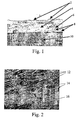
- FIG. 1 shows a cross section of a consolidated precision nonwoven fabric according to the invention with PEEK as a fused fiber, consolidated on steel sheet with a nearly optimal density and almost no porosity.
- the reference numeral 2 designates the interface to a steel substrate.
- a high-performance thermoplastic 4 is applied on the steel substrate.
- additives 6 are introduced.
- carbon fibers 8 are introduced.
- At the bottom of the sectional image is still an embedding 10 can be seen.
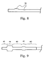
- FIG. 2 shows a scanning electron microscope (SEM) recording of a fracture pattern of a consolidated nonwoven mat according to the invention with PPSO 2 as a melt fiber and carbon fiber as a reinforcing fiber.
- the non-woven mat shows a relatively high porosity and a density of 1.23 g / cm3. In the recording, the pores are identified by the reference numeral 12.
- the E-glass reinforcing fibers can be seen at 14 and in the high-performance thermoplastics 16th embedded.
- FIG. 3 For example, a typical cylinder head gasket according to the invention is shown in plan view, which is formed from the gasket material according to the invention.
- the reference numeral 18 indicates a zone with higher density and higher spring stiffness and low compressibility.
- the zone indicated by reference numeral 26 has a lower density than that of the zone 18, lower spring stiffness and higher compressibility and higher springback.
- Zones 20, 22 and 24 in Fig. 3 have a medium density and average spring stiffness, average compressibility and medium springback.
- Reference numerals 30, 32 and 34 denote different regions of the seal according to the invention, which is achieved by the mosaic-like assembly of the respective materials 30, 32 and 34.
- FIG. 4 a layer structure of a seal on a substrate 34 is shown. Layers 30, 32 having different densities, moduli of elasticity and resilience properties are shown on the substrate 34. In this case, a number of layers, each mosaic-like, are superimposed on the continuous substrate 34. This can be obtained any design of a seal.
- the seal of the present invention is not dependent on a substrate layer 34.
- the seal of the present invention is also not limited to a particular number of different layers 30, 32.
- the layer 30 is a high-density layer and that the layer 32 is a lower-density layer.
- the representation in FIG. 4 shows the nesting principle in mosaic form, before the consolidation of the nonwovens. In FIG. 4 the mosaic is clearly visible both in the top view (not shown) and in the sectional view.
- FIG. 5 the seal is limited to two gasket layers 32 and 30, wherein the gasket layer 32 is placed on the continuous gasket layer 30.
- the representation in FIG. 5 shows a simple hang up before consolidating the nonwovens.
- a mosaic-like structure can only be seen in the top view (not shown).
- the seal is also limited to two gasket layers 32 and 30.
- the structure shown can be made by pressing a in FIG. 5 shown sealing structure can be achieved.
- the structure shown may also be a mosaic-like combination the layers 30 and 32 on a layer 30 accordingly FIG. 6 getting produced.
- FIG. 7 essentially represents the in Fig. 6 represented sealing structure which is provided in a region with a bead 36 in order to achieve a higher elasticity.
- the reference numeral 38 in FIG. 8 a topographical shape of the seal to obtain areas of different density and elasticity.
- zones of higher elasticity 44, zones of medium elasticity 42 and zones of low elasticity 40 are arranged by a topographical shape of the seal to produce a staggered sealing effect in the sealing plane.
- FIGS. 10 and 12 Combinations of a topographic shape and a mosaic juxtaposition of sealing materials are shown.
- FIG. 11 is shown a functional layer with a bead and a corresponding topographic shape and a combination of sealing or nonwoven layers.
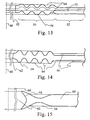
- FIGS. 13 to 15 show sectional views of the seal according to the invention with different forms for compression molding.
- FIG. 13 shows a sectional view of the seal according to the invention with a pronounced as a comb profile molding.
- the seal has an end face 62 which faces the cavity to be sealed. In a region adjacent to the end face 62, the seal is provided with an offset comb profile 50.
- the offset comb profile 50 has sealing projections 54 offset from one another on both sides of the seal.
- the transition from a series of consecutive full corrugations of FIG. 12 to an offset comb profile 50 is fluid, wherein the offset comb profile 50 may have structures that are smaller than the thickness of the seal.
- the lines 64 illustrate the further course of the seal, when it is assumed that it seals a circular axis around the gap 66 or cavity.
- the seal shown further comprises a sheet steel layer 31.
- FIG. 14 shows a sectional view of a seal according to the invention with a pronounced as a comb profile molding.
- the seal points like the seal of FIG. 13 an end face 62 faces the cavity to be sealed.
- the seal is provided with a comb profile, which in contrast to the seal of FIG. 13 is not offset.
- the comb profile has seal projections 54 which are substantially superimposed on both sides of the seal.
- lines 64 illustrate the further course of the seal when it is assumed that it seals a gap or cavity about the axis 66.
- the seal is in FIG. 14 also shown with attached nonwoven layers 54, which can change the sealing properties of the seal adjacent to the comb profile targeted.
- the seals of FIGS. 13 and 14 can also be provided with fleece layers, which also extend into the region of the comb profile. It is also possible to build the comb profile in the manner of a stepped pyramid of superimposed nonwoven layers.
- This multilayer structure can be combined with a compression molding, which in the FIGS. 13 and 14 have shown embodiments of comb profiles.
- the seal is executed in one area by rows of sealing surfaces arranged one behind the other. The sealing surfaces form a comb-like structure on average.
- FIG. 15 is a functional position provided by a compression molding with a double sealing lip 58.
- the end face 62 is designed as a double sealing lip 58.
- the sealing lips 58 are pressed at a voltage applied to the surface 62 overpressure against the (not shown) to be sealed surfaces, which enhances their sealing effect.
- Figures 64 illustrate the further course of the seal which seals one around an axis 66 circular gap.
- the seal according to the invention can also have inserted elastomer parts, ceramic materials and metallic materials in one embodiment.
- the gaskets may include bead rings, laid-on or inlaid metal rings, unsealed metal rings and beaded surrounds both inside and outside.
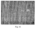
- FIG. 16 shows a plan view in 40-fold magnification (light microscope) of the HD variant (100% density, ie, 1.4 g / cm 3 ) of the inventive material according to Example 3 with the composition described below.
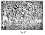
- FIG. 17 For example, a 40x magnification (light microscope) top view of the LD variant (65% density, ie 0.9 g / cm 3 ) of the material of Example 3 is shown.
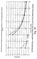
- FIG. 18 Deformation curves of the material according to the invention according to Example 3 (according to the invention) using the example of the LD and HD version with different material densities, tested at 250 ° C, shown. Standard rings 55x75 mm, web widths of 0.75 mm were tested at 250 ° C and the in Fig. 18 obtained curves shown.
- the materials according to the invention fulfilled the requirements with regard to the adaptability and show the controllability of the adaptability via the material density.
- Example 3 the reduction of the leakage rate by density reduction is shown by the example of Example 3 (invention) in the HD and LD versions.
- the inventive samples met the leakage criterion with N 2 / l bar at R max . 12 ⁇ m.
- the test specimen again consisted of a standard ring with 55x75 mm, beaded.
Landscapes
- Engineering & Computer Science (AREA)
- Chemical & Material Sciences (AREA)
- General Engineering & Computer Science (AREA)
- Materials Engineering (AREA)
- Organic Chemistry (AREA)
- Mechanical Engineering (AREA)
- Laminated Bodies (AREA)
- Sealing Material Composition (AREA)
Description
Die vorliegenden Erfindung betrifft einen unter Anwendungsbedingungen von bis zu 330°C thermisch stabilen Hochleistungs-Flachdichtungswerkstoff, der durch Verpressung von einer oder mehreren Faservliesen oder Faservliesmatten unter Druck und Temperatur zu einem so genannten composite film, d. h. zu einer (faser)verstärkten Folie unter Wärme und Druck konsolidiert wird. Der Flachdichtungswerkstoff eignet sich zur Verwendung für hoch beanspruchte Dichtungen und insbesondere für Zylinderkopfdichtung. Der erzeugte composite film bzw. die (faser- und/oder binder-)verstärkte Folie weisen Schichtdicken von 0,01 mm bis 3 mm auf, welche in einem Arbeitsgang aus einer oder mehreren Vlieslagen realisiert werden können. Somit können mit diesen erfindungsgemäßen Werkstoffen erstmalig Minimalschichtdicken von 0,01 mm erzielt werden.The present invention relates to a high performance flat gasket material which is thermally stable under conditions of use of up to 330 ° C and which is compressed by compression of one or more nonwoven fabrics or nonwoven mats under pressure and temperature into a so-called composite film, i. H. is consolidated into a (fiber) reinforced film under heat and pressure. The gasket material is suitable for use in highly stressed seals and in particular for cylinder head gaskets. The composite film produced or the (fiber and / or binder) reinforced film have layer thicknesses of 0.01 mm to 3 mm, which can be realized in one operation of one or more nonwoven layers. Thus, with these materials according to the invention minimum layer thicknesses of 0.01 mm can be achieved for the first time.
Die vorliegende Erfindung betritt daher auch Dichtungen, insbesondere Zylinderkopfdichtungen, die aus dem zuvor erwähnten neuartigen Flachdichtungswerkstoff, der gegebenenfalls auf ein flächiges Substrat aufgebracht sein kann, bestehen. Als Substrat kann ein Metallsubstrat, wie ein Substrat aus Aluminium oder einer Aluminiumlegierung dienen. In besonderen Ausführungsformen der Erfindung kann aber auch ein Gewebe, ein Gestrick, Papiere oder (keramische) Platten als Substrat dienen. Der Flachdichtungswerkstoff kann dann in einer weiteren Ausführungsform zwischen zwei Substraten, beispielsweise zwei Geweben angeordnet und unter Druck und erhöhter Temperatur konsolidiert worden sein. In einer weiteren Ausführungsform können auch mehrere auf ein Substrat, beispielsweise ein Gewebe aufgebrachte Flachdichtungswerkstoffe, übereinander gestapelt und unter Druck und erhöhter Temperatur konsolidiert worden sein. Die Dichtung besteht dann aus einem Laminat mit Substraten und dazwischen gelagerten Flachdichtungswerkstoffen.The present invention therefore also enters seals, in particular cylinder head gaskets, which consist of the aforementioned novel gasket material, which may optionally be applied to a planar substrate. As the substrate, a metal substrate such as a substrate made of aluminum or an aluminum alloy can be used. In particular embodiments of the invention, however, a woven fabric, a knitted fabric, papers or (ceramic) plates can also serve as a substrate. The gasket material may then in a further embodiment have been arranged between two substrates, for example two fabrics, and consolidated under pressure and elevated temperature. In a further embodiment, a plurality of flat sealing materials applied to a substrate, for example a woven fabric, may also be stacked on top of one another and consolidated under pressure and elevated temperature. The gasket then consists of a laminate with substrates and interposed gasket materials.
Im Stand der Technik dienen bei Dichtungen Beschichtungen oft nicht nur lediglich dazu, die beschichteten Materialien gegen Medieneinflüsse oder Ähnliches zu schützen, sondern auch dazu, die Abdichtungseigenschaften der Dichtung zu verbessern. Dazu muss eine hohe Anpassungsfähigkeit der Beschichtung an die abzudichtenden Gegenflächen geschaffen werden, um so Unebenheiten etc. auszugleichen. Weiterhin muss die Beschichtung gleichzeitig eine gewisse Rückfederung aufweisen, um dynamische Bauteilschwingungen auszugleichen. Sofern sie nicht durch Rückfederung des Dichtungswerkstoffes oder bei Metalldichtungen der Sickenelemente in der Dichtung ausreichend gegeben ist, kommt der Beschichtung eine entscheidende Abdichtungsfunktion zu.In the prior art, in coatings, coatings often serve not only merely to protect the coated materials against media effects or the like, but also to improve the sealing properties of the gasket. For this purpose, a high adaptability of the coating must be created to the sealed mating surfaces, so as to compensate for bumps, etc. Furthermore, the coating must simultaneously have a certain resilience to compensate for dynamic component vibrations. In case you is not sufficiently given by spring back of the sealing material or metal seals of the bead elements in the seal, the coating has a crucial sealing function.
Bei bestimmten Anforderungsprofilen sind zusätzlich gute Dauergleiteigenschaften der Beschichtung und ein geringes Setzverhalten unter Einfluss von Druck und Temperatur gefordert. Gute Dauergleiteigenschaften sind gekoppelt an dauerhaft beständige Oberflächen mit geringstem Verschleiß.For certain requirement profiles, good continuous sliding properties of the coating and a low setting behavior under pressure and temperature are additionally required. Good continuous sliding properties are coupled to permanently resistant surfaces with minimal wear.
Ein Beispiel einer Dichtung, welche sowohl gute Dauergleiteigenschaften als auch hohe Anpassungsfähigkeit an die abzudichtenden Gegenflächen aufweisen sollte, ist die Zylinderkopfdichtung. Bislang werden Zylinderkopfdichtungen üblicherweise mit einer dünnen Beschichtung von einigen um-Dicke versehen, welche die Anpassungsfähigkeit der Dichtung an Unebenheiten und Rauhigkeiten der abzudichtenden Gegenflächen wie Motorblock und Zylinderkopf verbessern sollen. Solche Beschichtungen sind üblicherweise Beschichtungen aus Kautschuk, welche bei Metalldichtungen auf das metallische Substrat aufgetragen werden und weisen üblicherweise eine Dicke von etwa 20 µm auf. Ein derartiger Aufbau, d. h., ein metallisches mit einer Fluorkautschukbeschichtung versehenes Substrat stellt den zurzeit üblichen Aufbau einer so genannten MLS (multi-layer-steel)-Zylinderkopfdichtung dar. Ein großer Schwachpunkt von Fluorkautschukbeschichtungen ist dabei der hohe Reibungskoeffizient der Fluorkautschukbeschichtung zu den Dichtflächen, die relativ geringe Haftung der Beschichtung auf dem Stahlsubstrat, die relativ große Abhängigkeit der Standfestigkeit von der Betriebstemperatur und der Wärmestabilität und die damit einhergehende niedrige Verschleißbeständigkeit der Beschichtung.An example of a gasket, which should have both good continuous sliding properties as well as high adaptability to the mating surfaces to be sealed, is the cylinder head gasket. Heretofore, cylinder head gaskets are usually provided with a thin coating of several μm thickness which is intended to improve the adaptability of the gasket to unevenness and roughness of the mating surfaces such as engine block and cylinder head to be sealed. Such coatings are usually coatings of rubber, which are applied to the metallic substrate in metal seals and usually have a thickness of about 20 microns. Such a construction, d. That is, a metallic substrate provided with a fluororubber coating is the current construction of a so-called MLS (multi-layer steel) cylinder head gasket. A major weak point of fluororubber coatings is the high coefficient of friction of the fluororubber coating to the sealing surfaces, the relatively low adhesion the coating on the steel substrate, the relatively high dependence of the stability of the operating temperature and the thermal stability and the associated low wear resistance of the coating.
Das in
Zunächst wurde, wie gesagt, die "multi-slide"-Beschichtung für die Metall-Zylinderkopfdichtungen wie z. B. "Monomet®" entwickelt. Dies hat eine zentrale Bedeutung sowohl für die Abdichtfunktion als auch für die Laufeigenschaften des Motors. Bei dem "multi-slide"-Verfahren wird eine Mehrlagenbeschichtung aus unterschiedlichen Kunststoffen als Pulver aufgetragen und danach gesintert.First, as mentioned, the "multi-slide" coating for the metal cylinder head gaskets such. B. "Monomet ® " developed. This is of central importance for both the sealing function and the running characteristics of the engine. In the "multi-slide" process, a multilayer coating of different plastics is applied as a powder and then sintered.
Insgesamt erreicht man aber mit dieser Technik eine minimale Gesamtschitdicke der "multi-slide"-Beschichtung von ca. 60 µm. Die Anpassungsfähigkeit der "multi-slide"-Beschichtung wird durch einen hohen Anteil von PTFE oder PFA erreicht. Eine gute Haftung der Beschichtung zum Substrat wird durch einen hohen Anteil eines Hochtemperaturthermoplasten, wie z. B. PEEK erzielt.Overall, however, this technique achieves a minimum overall thickness of the "multi-slide" coating of approximately 60 μm. The adaptability of the "multi-slide" coating is achieved by a high proportion of PTFE or PFA. Good adhesion of the coating to the substrate is achieved by a high proportion of a high-temperature thermoplastic, such. B. PEEK achieved.
Wünschenswert ist aber auch, wie dies bereits in der
Eine Faserverstärkung der zuvor beschriebenen "multi-slide"-Beschichtungen ist in der Praxis nicht vorstellbar, weil übliche Faserdurchmesser z. B. bei Carbonfasern im Bereich von 7 µm und bei Glasfasern im Bereich von zwischen 6 und 9 µm liegen. Organische Fasern sind in der Regel noch wesentlich dicker und liegen bei Durchmessern von 12 bis 25 µm. Die Einzelschichtdicke kann aber, wie bereits oben festgestellt wurde, nur 6 µm betragen. Weiterhin ist zu berücksichtigen, dass jede einzelne Schicht bei dem oben beschriebenen "multi-slide"-Verfahren einzeln "gesintert" oder konsolidiert wird. Das Aufschmelzen des PEEK-Pulvers bei 380 °C führt aber zu einer starken Beanspruchung des Polymers und teilweise schon zu einem Abbau.A fiber reinforcement of the previously described "multi-slide" coatings is not conceivable in practice, because usual fiber diameter z. B. in carbon fibers in the range of 7 microns and glass fibers in the range of between 6 and 9 microns. Organic fibers are usually much thicker and are in diameters of 12 to 25 microns. However, as already stated above, the single layer thickness can only be 6 μm. Furthermore, it should be noted that each individual layer is individually "sintered" or consolidated in the "multi-slide" process described above. The melting of the PEEK powder at 380 ° C but leads to a heavy stress on the polymer and sometimes already to a degradation.
Insgesamt ist die "multi-slide"-Beschichtung als Kombination der Werkstoffe PEEK mit PTFE sicherlich daher ein neuer Weg, um den zunehmenden Temperaturen und der höheren Leistungsdichte moderner Motoren zu begegnen. Um diesen erhöhten Anforderungen an den Dichtungswerkstoff wirklich gerecht zu werden und wirtschaftlich zu produzieren, benötigt man aber ein Produkt, das bessere Eigenschaften und niedrigere Prozesskosten bringt als das "multi-slide" Verfahren.Overall, the "multi-slide" coating as a combination of PEEK with PTFE materials is certainly a new way of counteracting the increasing temperatures and higher power density of modern engines. In order to really meet these increased demands on the sealing material and to produce economically, however, a product is required which offers better properties and lower process costs than the "multi-slide" method.
Im Stand der Technik ist die Vliesstoffherstellung mit dem Nassverfahren in von der Papierherstellung abgeleiteten typischen Verfahrensweisen bekannt. In "
Derartige Verfahren werden im Wesentlichen für die Papierherstellung wie z. B. bei Synthesefaserpapier, Teebeutelpapier, Luftfilterpapier oder auch bei Zigarettenumhüllungspapieren eingesetzt.Such methods are essentially used for papermaking such. B. used in synthetic fiber paper, tea bag paper, air filter paper or cigarette wrapping papers.
Das Verfahren des Standes der Technik wird somit nur für die Herstellung von Spezialpapieren oder speziellen technischen Vliesstoffen als Endprodukt angewandt.The prior art method is thus used only for the production of specialty papers or special engineering nonwovens as the final product.
Aus
Die
In der
- A. PEI-Fasern und Verstärkungsfasern werden trocken zu einem Mischvlies vermischt,
- B. das Mischvlies wird durch Nadeln verfestigt,
- C. das verfestigte Mischvlies wird erwärmt und
- D. zum Halbzeug verpresst.
- A. PEI fibers and reinforcing fibers are dry blended into a blended nonwoven fabric,
- B. the mixed fleece is solidified by needling,
- C. the solidified mixed fleece is heated and
- D. pressed to semis.
Die
Die
Schließlich beschreibt die
Auch die
Die
Daher ist es Aufgabe der vorliegenden Erfindung, einen bei Anwendungsbedingungen von bis zu 330°C thermisch stabilen Hochleistungs-Flachdichtungswerkstoff mit hoher Festigkeit, guten Dämpfungseigenschaften, besten Gleit- und Verschleißeigenschaften und einstellbarer Dichte bereitzustellen, welcher für Dichtungsanwendungen und insbesondere Zylinderkopfdichtungsanwendungen geeignet ist.Therefore, it is an object of the present invention to provide a high performance, high strength, good damping, best sliding and wear characteristics and adjustable density high performance gasket material under service conditions up to 330 ° C which is suitable for gasket applications, and in particular cylinder head gasket applications.
Die obige Aufgabe wird durch den unter Anwendungsbedingungen von bis zu 330°C thermisch stabilen Hochleistungs-Flachdichtungswerkstoff in Form einer faser- und/oder binderverstärkten Verbundfolie (composite film) gelöst. Die erfindungsgemäße Verbundfolie weist eine Gesamtschichtdicke von 0,01 mm bis 3 mm auf und ist herstellbar durch Verpressung von wenigstens einem oder mehreren Faservliesen unter Druck und Temperatur, wobei die einzelnen Faservliese bzw. Faservliesmatten ein Flächengewicht von 8 bis 400 g/m2, insbesondere von 50 bis 100g/m2, aufweisen.The above object is achieved by the under the use conditions of up to 330 ° C thermally stable high performance flat gasket material in the form of a fiber and / or binder-reinforced composite film. The composite film according to the invention has a total layer thickness of 0.01 mm to 3 mm and can be produced by pressing at least one or more nonwoven fabrics under pressure and temperature, wherein the individual nonwoven or nonwoven mats has a basis weight of 8 to 400 g / m 2 , in particular from 50 to 100 g / m 2 .
Die Faservliese enthalten die folgenden Komponenten:
- (a) mindestens eine erste Faser aus einem Thermoplasten, ausgewählt aus der Gruppe, bestehend aus Polyetheretherketon (PEEK), Poly-p-phenylensufild (PPS), Polyetherimid (PEI), Polyetheramid (PEA), Polyamid (PA), Polysulfon (PSU), Polyvinylethersulfon (PPSU), Polyethersulfon (PES), Polyaryletherketon (PAEK), Polyetherketon (PEK), Polyoxymethylen (POM) und Gemischen davon, oder aus der Gruppe der metallischen Schmelzfasern mit einem Schmelz- oder Erweichungspunkt der Metallfasern von unter 450°C, als Schmelzfaser, in
einem Gewichtsanteil von 30 bis 97 %, bezogen auf die gesamte Formulierung des Faservlieses, und einer mittleren Faserlängenverteilung der Schmelzfaserim Bereich von 0,1mm bis 30 mm, - (b) gegebenenfalls mindestens eine zweite Verstärkungsfaser, ausgewählt aus der Gruppe, bestehend aus Glasfasern, Aramidfasern, Carbonfasern, Keramikfasern, oxidierten Polyphenylensulfid-(PPSO2)-Fasern, Metallfasern, Polyimidfasern, Polybenzimidazolfasern, Polybenzoxazolfasern und Naturfasern und Gemischen davon, dessen Temperaturstabilität größer ist als die der Schmelzfaser, mit einem Gewichtsanteil von 3 bis 67 %, bezogen auf die gesamte Formulierung des Faservlieses und einer mittleren Faserlängenverteilung der verstärkungsfaser
im Bereich von 0,1mm bis 30 mm, mit der Maßgabe, dass die mittlere Faserlängenverteilung der Schmelzfaser kleiner ist als die der Verstärkungsfaser - (c)
bis zu 60 Gewichtsprozent, insbesondere 3bis 10 Gew.-%, eines Binders, bezogen auf die gesamte Formulierung des Faservlieses, wobei die Komponenten (a), (b) und (c) jeweils 100 Gew.-% ergeben.
- (a) at least one thermoplastic first fiber selected from the group consisting of polyetheretherketone (PEEK), poly-p-phenylene-sis (PPS), polyether-imide (PEI), polyether-amide (PEA), polyamide (PA), polysulfone (PSU ), Polyvinyl ether sulfone (PPSU), polyether sulfone (PES), polyaryl ether ketone (PAEK), polyether ketone (PEK), polyoxymethylene (POM) and mixtures thereof, or from the group of metallic melt fibers having a melting or softening point of the metal fibers below 450 ° C , as a melt fiber, in a proportion by weight of 30 to 97%, based on the total formulation of the nonwoven fabric, and an average fiber length distribution of the melt fiber in the range of 0.1 mm to 30 mm,
- (b) optionally, at least one second reinforcing fiber selected from the group consisting of glass fibers, aramid fibers, carbon fibers, ceramic fibers, oxidized polyphenylene sulfide (PPSO 2 ) fibers, metal fibers, polyimide fibers, polybenzimidazole fibers, polybenzoxazole fibers, and natural fibers and mixtures thereof whose temperature stability is greater is that of the melt fiber, in a weight fraction of 3 to 67%, based on the entire formulation of the nonwoven fabric and an average fiber length distribution of the reinforcing fiber in the range of 0.1 mm to 30 mm, provided that the average fiber length distribution of the melt fiber is smaller is as the reinforcing fiber
- (c) up to 60% by weight, in particular 3 to 10% by weight, of a binder based on the total formulation of the nonwoven fabric, wherein components (a), (b) and (c) each give 100% by weight.
Weiterhin können die Faservliese zusätzlich zu den 100 Gew.-% der Komponenten (a), (b) und (c) 0,1 bis 80 Gew.-Teile von üblichen Additiven und Zuschlagsstoffen enthalten, ausgewählt aus Fasern, Fibrillen, Fibriden, nanoskaligen Zusätzen im Größenbereich von 5 bis 300 nm, folienartigen Strukturen, Pulpe, metallischen oder keramischen Pulvern, anorganischen Mikrohohlkugeln mit einer durchschnittlichen Partikelgröße von 10 bis 300 µm und einer Druckfestigkeit von 3,5 bis 70 MPa und Mischungen hiervon.Further, in addition to the 100% by weight of components (a), (b) and (c), the nonwoven fabrics may contain from 0.1 to 80 parts by weight of conventional additives and adjuncts selected from fibers, fibrils, fibrids, nanoscale Additives in the size range of 5 to 300 nm, film-like structures, pulp, metallic or ceramic powders, inorganic hollow microspheres having an average particle size of 10 to 300 microns and a compressive strength of 3.5 to 70 MPa and mixtures thereof.
In einer besonderen Ausführungsform der Erfindung werden Zusätze in Form von Fibriden eingesetzt.In a particular embodiment of the invention, additives in the form of fibrids are used.
Erstmalig ist es erfindungsgemäß möglich, langfaserverstärkte Folien (composite films) oder diese als Beschichtungen auf Substraten für die Anwendung als Flachdichtung, insbesondere als Zylinderkopfdichtung, in einem Arbeitsgang in Schichtdicken von 0,01 mm bis 3 mm aus wenigstens einer Vlieslage zu realisieren.For the first time, it is possible according to the invention to realize long-fiber-reinforced films (composite films) or these as coatings on substrates for use as a flat gasket, in particular as a cylinder head gasket, in one operation in layer thicknesses of 0.01 mm to 3 mm of at least one nonwoven layer.
Der erfindungsgemäße Flachdichtungswerkstoff in Form einer faser- und/oder binderverstärkten Folie ist herstellbar durch Verpressung von mindestens einer Faservliesmatte unter Druck und erhöhter Temperatur. Der Verpressungsvorgang kann diskontinuierlich oder auch kontinuierlich erfolgen. Die Verpressung erfolgt erfindungsgemäß unter einem Druck von 0,05 bis 15 N/mm2, einer Temperatur von bis zu 450 °C, d. h. einer Temperatur, die über dem Schmelzpunkt oder dem Erweichungspunkt der Schmelzfaser liegt. Die Verpressungszeiten liegen bei 0,1 bis 15 Minuten.The flat sealing material according to the invention in the form of a fiber and / or binder-reinforced film can be produced by pressing at least one nonwoven mat under pressure and elevated temperature. The compression process can be discontinuous or continuous respectively. The pressing is carried out according to the invention under a pressure of 0.05 to 15 N / mm 2 , a temperature of up to 450 ° C, ie a temperature which is above the melting point or the softening point of the melt fiber. The compression times are 0.1 to 15 minutes.
Erfindungsgemäß kann somit erstmalig durch den Einsatz von hoch präzisen Ausgangsvliesen, insbesondere aus PEEK oder PPS mit Carbonfaser oder Glasfaser oder organischen Hochleistungsfasern und zusätzlichen additiven Fasern in unterschiedlichen Mischungsverhältnissen, Verstärkungsfaseranteilen und Faserlängen von mindestens 0,1-30 mm eine faserverstärkte Folie mit einer Minimaldicke von 0,01 mm hergestellt werden. Die Konsolidierung der Vliese kann dabei in einer Ausführungsform direkt auch auf einem Substrat, insbesondere einem Stahlsubstrat oder einem Substrat aus Aluminium oder einer Aluminiumlegierung, erfolgen. Als weitere bevorzugte Substrate können Gewebe, Gestricke, Papiere oder keramische Platten dienen. In einer Ausführungsform der Erfindung wird das Faservlies auf einem Gewebe konsolidiert bzw. zwischen zwei Gewebe eingebracht und konsolidiert. Dabei handelt es sich um ein Verfahren, wodurch Vliese direkt auf das Substrat aufgebracht werden und z. B. in Taktpressen oder Doppelstahlbandpressen verpresst und der erfindungsgemäße Flachdichtungswerkstoff hergestellt wird. Die beheizten Pressen ermöglichen eine sowohl kontinuierliche als auch diskontinuierliche Herstellungsweise von Flachdichtungswerkstoffen oder Einzeldichtungen. Die Faservliesmatten aus den jeweiligen Werkstoffen können nacheinander auf das Substrat aufgebracht und konsolidiert werden. Somit ist es möglich, unterschiedliche Materialien miteinander zu kombinieren und auf diese Weise einen Gradientenwerkstoff herzustellen.Thus, according to the invention, for the first time by the use of highly precise starting nonwovens, in particular of PEEK or PPS with carbon fiber or glass fiber or organic high performance fibers and additional additive fibers in different mixing ratios, Verstärkungsfaseranteilen and fiber lengths of at least 0.1-30 mm, a fiber-reinforced film with a minimum thickness of 0.01 mm are produced. In one embodiment, the consolidation of the nonwovens can also take place directly on a substrate, in particular a steel substrate or a substrate made of aluminum or an aluminum alloy. Tissues, knits, papers or ceramic plates can serve as further preferred substrates. In one embodiment of the invention, the nonwoven fabric is consolidated on a fabric or introduced and consolidated between two fabrics. This is a process whereby nonwovens are applied directly to the substrate and z. B. pressed in tact presses or double steel belt presses and the flat gasket material according to the invention is produced. The heated presses allow both continuous and discontinuous production of gasket materials or single gaskets. The nonwoven mats made of the respective materials can be successively applied to the substrate and consolidated. Thus, it is possible to combine different materials with each other and produce in this way a gradient material.
Weiterhin ist es in einer besonderen Ausführungsform möglich, wie schon oben beschrieben wurde, die faser- und/oder binderverstärkte Verbundfolie zwischen zwei Gewebesubstrate einzubringen. Falls nun mehrere auf ein Gewebesubstrat aufgebrachte Verbundfolien übereinander unter Wärme und Druck konsolidiert werden, so erhält man einen Flachdichtungsverbundwerkstoff mit mehreren zwischengelagerten Substraten bzw. Verbundfolien.Furthermore, it is possible in a particular embodiment, as already described above, to introduce the fiber-reinforced and / or binder-reinforced composite film between two fabric substrates. If a plurality of composite films applied to a fabric substrate are then consolidated one above the other under heat and pressure, a flat gasket composite material having a plurality of intermediately stored substrates or composite films is obtained.
Erfindungsgemäß ist der Flachdichtungswerkstoff durch Verpressung von mindestens einer oder mehrerer, auch aus unterschiedlichen Materialien bestehenden, Faservliesmatten in einem beheizten Werkzeug unter einem Druck von 0,05 bis 15 N/mm2 herstellbar. Die Faservliesmatten enthalten mindestens eine erste Faser aus einem Hochleistungsthermoplasten der einer metallischen Faser als Schmelzfaser mit einem Gewichtsanteil von 30 bis 97%, bezogen auf die gesamte Formulierung des Faservlieses, und mindestens einer zweiten Verstärkungsfaser aus einem Hochleistungswerkstoff, dessen Temperaturstabilität größer ist als die der Schmelzfaser, mit einem Gewichtsanteil von 3 bis 67 %, bezogen auf die gesamte Formulierung des Faservlieses, sowie bis zu 60 Gew.-%, bezogen auf die gesamte Formulierung des Faservlieses, insbesondere 3 bis 10 Gew.-%, bezogen auf die gesamte Formulierung des Foservlieses, eines Binders, wobei die Anteile der gesamten Formulierung der Faservliesmatte gewichtsbezogen sind, mit der Maßgabe, dass die Faserlänge der Schmelzfasern in der mittleren Häufigkeitsverteilung kleiner sind als die der Verstärkungsfasern.According to the invention, the flat sealing material can be produced by pressing at least one or more nonwoven mats, also made of different materials, in a heated tool under a pressure of 0.05 to 15 N / mm 2 . The nonwoven mats contain at least a first high performance thermoplastic fiber of a metallic fiber as the fusing fiber at 30 to 97% by weight based on the entire nonwoven fiber formulation and at least one second high performance material reinforcing fiber whose temperature stability is greater than that of the fused fiber , With from 3 to 67% by weight, based on the total formulation of the nonwoven fabric, and up to 60% by weight, based on the total formulation of the nonwoven fabric, in particular from 3 to 10% by weight, based on the total formulation of the nonwoven fabric, a binder, wherein the proportions of the total formulation of the nonwoven mat are by weight, provided that the fiber length of the melt fibers in the average frequency distribution are smaller than that of the reinforcing fibers.
Dadurch, dass die mittlere Verteilung der Faserlänge der Schmelzfaser kleiner ist als diejenige der Verstärkungsfaser, wird eine homogene Vermischung der beiden Faserarten erreicht, sodass dann beim späteren Weiterverarbeiten des Halbzeuges eine einheitliche homogene Verteilung der Verstärkungsfaser in dem Faserverbundwerkstoff erfolgt. Die Faserausrichtung der Fasern in der Schicht kann isotrop oder anisotrop sein.Due to the fact that the average distribution of the fiber length of the melt fiber is smaller than that of the reinforcing fiber, a homogeneous mixing of the two fiber types is achieved so that a uniform, homogeneous distribution of the reinforcing fiber in the fiber composite material takes place during later further processing of the semifinished product. The fiber orientation of the fibers in the layer may be isotropic or anisotropic.
Im erfindungsgemäßen Flachdichtungswerkstoff weist die mindestens eine Schmelzfaser eine mittlere Faserlängenverteilung im Bereich von 0,1 mm bis 30 mm auf. Bevorzugt ist die Schmelzfaser 2 mm bis 6 mm und ganz besonders bevorzugt 1,5 mm bis 3 mm lang. Die Verstärkungsfaser aus dem Hochleistungswerkstoff weist ebenfalls eine mittlere Faserlängenverteilung im Bereich von 0,1 mm bis 30 mm auf, ist aber, wie durch Patentanspruch 1 definiert wird, jeweils in ihrer mittleren Faserverteilung immer größer wie die Schmelzfaser. Geeignete Faserlängen für die Verstärkungsfasern sind 0,1 mm bis 18 mm, besonders bevorzugt 3 mm bis 12 mm.In the flat gasket material according to the invention, the at least one melt fiber has an average fiber length distribution in the range from 0.1 mm to 30 mm. Preferably, the melt fiber is 2 mm to 6 mm and most preferably 1.5 mm to 3 mm long. The reinforcing fiber of the high-performance material also has an average fiber length distribution in the range of 0.1 mm to 30 mm, but is, as defined by claim 1, always larger in their average fiber distribution as the melt fiber. Suitable fiber lengths for the reinforcing fibers are 0.1 mm to 18 mm, more preferably 3 mm to 12 mm.
Fasern aus einem Thermoplasten, ausgewählt aus der gruppe, bestehend aus Polyetheretherketon (PEEK), Poly-p-phenylensufild (PPS), Polyetherimid (PEI), Polyetheramid (PEA), Polyamid (PA), Polysulfon (PSU), Polyvinylethersulfon (PPSU), Polyethersulfon (PES), Polyaryletherketon (PAEK), Polyetherketon (PEK), Polyoxymethylen (POM) und Mischungen hiervon, und aus der Grüppe der metallischen Schmelzfasern, z. B. aus Zink, Blei, Bismut, oder deren Legierungen. Voraussetzung ist nur, dass der Schmelz- oder Erweichungspunkt der Metallfasern unter 450°C liegt.Thermoplastic fibers selected from the group consisting of polyetheretherketone (PEEK), poly-p-phenylene-sis (PPS), polyether-imide (PEI), polyether-amide (PEA), polyamide (PA), polysulfone (PSU), polyvinylethersulfone (PPSU) , Polyethersulfone (PES), polyaryletherketone (PAEK), polyetherketone (PEK), polyoxymethylene (POM) and mixtures thereof, and from the group of metallic melt fibers, e.g. As zinc, lead, bismuth, or their alloys. The only condition is that the melting or softening point of the metal fibers is below 450 ° C.
Die Verstärkungsfasern (b) sind ausgewählt aus der Gruppe, bestehend aus Polybenzoxazol (PBO)-Fasem, Polyimid (PI)-Fasern, Polybenzimidazol (PBI)-Fasern, oxidierte Polyphenylensulfid (PPSO2)-Fasern, Metallfasern, Glasfasern, Aramidfasern, Carbonfasern, Keramikfasern, Naturfasern und Mischungen hiervon.The reinforcing fibers (b) are selected from the group consisting of polybenzoxazole (PBO) fibers, polyimide (PI) fibers, polybenzimidazole (PBI) fibers, oxidized polyphenylene sulfide (PPSO 2 ) fibers, metal fibers, glass fibers, aramid fibers, carbon fibers , Ceramic fibers, natural fibers and mixtures thereof.
Wie vorstehend bereits erläutert wurde, ist die erfindungsgemäß verwendete Faservliesmatte so aufgebaut, dass die einzelnen Fasern mit Hilfe eines Bindemittels untereinander fixiert sind. Die Fasern selbst sind dabei noch so vorhanden, wie sie eingesetzt worden sind und nur durch das Bindemittel miteinander verbunden. Dieser Aufbau der Faservliesmatte ist wichtig, da für den später herzustellenden Verbundwerkstoff ein Aufspreizen der Verstärkungsfasern und/oder eine inhomogene Mischung vermieden werden muss.As already explained above, the nonwoven mat used according to the invention is constructed so that the individual fibers are fixed to one another with the aid of a binder. The fibers themselves are still present as they have been used and only by the Binders joined together. This structure of the nonwoven mat is important because for the later produced composite material spreading of the reinforcing fibers and / or an inhomogeneous mixture must be avoided.
Bei den Bindemitteln (c) können gemäß der vorliegenden Erfindung solche eingesetzt werden auf Basis von Polyvinylalkohol (PVA), Polyvinylacetat (PVAC), Ethylenvinylacetat (EVA), Polyacrylat, Polyurethan (PUR), Polyaramid, Harzen, aus der Gruppe aus Melaminharz oder Phenolharz, Polyolefinen wie Polyethylen (PE), Polypropylen (PP) und Copolymeren hiervon.In the binders (c) according to the present invention, those based on polyvinyl alcohol (PVA), polyvinyl acetate (PVAC), ethylene vinyl acetate (EVA), polyacrylate, polyurethane (PUR), polyaramid, resins, melamine resin or phenolic resin can be used , Polyolefins such as polyethylene (PE), polypropylene (PP) and copolymers thereof.
Unter Aramidfasern werden im Zusammenhang der vorliegenden Erfindung solche nach DIN 60 001 Teil 3 (1988) verstanden, d. h. Chemiefasern aus synthetischen Polymeren mit aromatischen Kettengliedern, die zu mindestens 85% Massenanteil direkt durch Aramidgruppen zu linearen Makromolekülen verbunden sind und bei denen bis zu 50% der Amidbindungen durch Imidbindungen ersetzt sein können (vgl.
Der Binder (c) kann eine Dispersion sein und faserartigen, folienartigen, fibrillenartigen oder fibridartigen Charakter aufweisen. Dabei werden unter Fibriden kurze hochaufgesplittete, nicht spinnfähige Fasern mit sehr großen Oberflächen verstanden. Einsetzbar sind sie z. B. aus Polyolefinen (PP, PE-HD) und können als Bindefasem z. B. zum Phenolharzersatz dienen (bzgl. der Definition der Fibride verweisen wir auf
Die erfindungsgemäß verwendete Faservliesmatte kann selbstverständlich auch noch Additive (d) enthalten. Solche Additive können eingesetzt werden, um die Eigenschaften der Faservliesmatte und somit auch nachfolgend des mit der Faservliesmatte hergestellten Faserverbundwerkstoffes zu beeinflussen. Gemäß der vorliegenden Erfindung können deshalb Additive eingesetzt werden, die Eigenschaften wie elektrische Leitfähigkeit, Wärmeleitfähigkeit, Reibungsverhalten, Temperaturbeständigkeit, Schlagzähigkeit, Festigkeit oder die Abrasionsbeständigkeit beeinflussen. Derartige Additive können ebenfalls z. B. in Form von Fasern, Fibrillen, Fibriden, Folien oder Pulpen eingesetzt werden. Die Additive können sowohl metallische oder keramische wie auch organische Pulver sein.Of course, the nonwoven mat used according to the invention may also contain additives (d). Such additives can be used to influence the properties of the nonwoven mat and thus also subsequently of the fiber composite produced with the nonwoven mat. According to the present invention, therefore, additives which affect properties such as electrical conductivity, thermal conductivity, frictional behavior, temperature resistance, impact resistance, strength or abrasion resistance can be used. Such additives can also z. B. in the form of fibers, fibrils, fibrids, films or pulps. The additives may be metallic or ceramic as well as organic powders.
Wesentlich ist nun, dass die erfindungsgemäß eingesetzte Faservliesmatte ein sehr geringes Flächengewicht besitzt. Darüber hinaus kennzeichnend ist die hohe Gleichmäßigkeit des Flächengebildes in Längs- und Querrichtung hinsichtlich der Dicke und Faserverteilung. Die Faservliesmatte weist je nach eingesetzten Verstärkungssfasern und Schmelzfasern und dessen Gewichtsanteile ein Flächengewicht von 8 bis 400 g/m2, bevorzugt von 50 bis 100 g/m2 auf und kann eine Dichte von 30 bis 500 kg/m3 für organische Faserstoffe, bevorzugt 100 bis 200 kg/m3 aufweisen. Für die Verwendung von metallischen Fasern kann die zuvor genannte Raumdichte weit überschritten werden. Die verwendete Faservliesmatte (als Vorprodukt zum composite film) ist bevorzugt 0,1 mm bis 30 mm, besonders bevorzugt 0,15 mm bis 1 mm dick. Die geringe Flächenmasse in großer Homogenität ermöglicht, dass beim späteren Verpressungsvorgang sehr dünne, auch langfaserverstärkte Folien (composite films) hergestellt werden können.It is essential that the nonwoven mat used according to the invention has a very low weight per unit area. In addition, the high uniformity of the fabric in the longitudinal and transverse directions in terms of thickness and fiber distribution is characteristic. The nonwoven mat has, depending on the used reinforcing fibers and melt fibers and its Weight has a basis weight of 8 to 400 g / m 2 , preferably from 50 to 100 g / m 2 and may have a density of 30 to 500 kg / m 3 for organic fibers, preferably 100 to 200 kg / m 3 . For the use of metallic fibers, the aforementioned bulk density can be far exceeded. The nonwoven mat used (as a precursor to the composite film) is preferably 0.1 mm to 30 mm, more preferably 0.15 mm to 1 mm thick. The low surface mass in high homogeneity allows that during the subsequent compression process very thin, even long-fiber reinforced films (composite films) can be produced.
Die für die Herstellung der Flachdichtungswerkstoffe eingesetzte Faservliesmatte kann weiterhin so aufgebaut sein, dass auf mindestens einer Außenseite der Faservliesmatte ein flächiges Substrat aufgebracht ist. Die Faservliesmatte bildet dann damit eine Funktionsschicht im weiteren Verarbeitungsgang, d. h., wenn das Halbzeug zu einem Endprodukt verarbeitet wird, wobei diese Funktionsschicht bestimmte Funktionen, wie eine Leitfähigkeit oder auch eine spezielle Klebefunktion, übernimmt. Das flächige Substrat kann dabei in Form eines Metallsubstrates, Gewebes, Geleges, Papiers oder Vlieses ausgebildet sein.The nonwoven mat used for the production of the flat sealing materials can furthermore be constructed such that a planar substrate is applied to at least one outer side of the nonwoven mat. The nonwoven mat then forms a functional layer in the further processing step, d. h., When the semifinished product is processed into an end product, said functional layer assumes certain functions, such as a conductivity or a special adhesive function. The planar substrate may be formed in the form of a metal substrate, tissue, Geleges, paper or nonwoven.
Ein Verfahren zur Herstellung einer Faservliesmatte, wie sie vorstehend beschrieben ist, sieht vor, dass die Schmelzfaser, um die Verstärkungsfaser in einem Dispergiermittel, bevorzugt Wasser, dispergiert werden, und dass dann eine kontinuierliche Vliesbildung auf einem Siebband durch Filtration erfolgt und anschließend eine Verfestigung und Trocknung des Vlieses erfolgt. Das Bindemittel kann dabei während des Dispergierschrittes und/oder während der Vliesbildung zugesetzt werden.A process for producing a nonwoven mat as described above provides that the melt fiber is dispersed around the reinforcing fiber in a dispersing agent, preferably water, and then continuous web formation is accomplished by filtration on a screen belt followed by solidification and Drying of the fleece takes place. The binder may be added during the dispersing step and / or during web formation.
Gleichfalls ist es möglich, die Additive während des Dispergierschrittes oder während der Vliesbildung zuzusetzen.Likewise, it is possible to add the additives during the dispersing step or during web formation.
Erfindungsgemäß ist es möglich, einen Flachdichtungswerkstoff zu erzielen, dessen Dichte und Dicke sowohl durch die Dichte und Dicke, als auch durch die Rezeptur der eingesetzten Vliese als auch durch die Verpressungs- (Konsolidierungs-) Parameter gesteuert werden kann. Dadurch ist es nun möglich, Faserverbundwerkstoffe mit einer Dichte herzustellen, die zwischen 0,25 und 6 g/cm3 liegt. Die Dicke der erfindungsgemäß hergestellten faserverstärkten Folie liegt im Bereich zwischen 0,01 bis 3 mm. Durch die Auswahl der Vliesbildung, durch geeignete Wahl der Verfahrensparameter kann ein gradiertes Vlies erzeugt werden, d. h., es können Übergänge von hohem Anteil an z. B. PEEK zu einem hohen Anteil an Verstärkungsfasern, sowohl in einem Einschicht- als auch in einem Mehrschichtaufbau erzielt werden. Somit ist ein kontinuierlicher Konzentrationswechsel von hoch haftfähigem reinem PEEK zu einem optimal faserverstärkten (langfaserverstärkten) Thermoplastcompound möglich.According to the invention, it is possible to achieve a flat sealing material whose density and thickness can be controlled both by the density and thickness, as well as by the formulation of the nonwovens used and by the compression (consolidation) parameters. This makes it possible to produce fiber composites with a density of between 0.25 and 6 g / cm 3 . The thickness of the fiber-reinforced film produced according to the invention is in the range between 0.01 to 3 mm. By selecting the web formation, by a suitable choice of the process parameters, a graded web can be produced, ie, transitions of a high proportion of z. As PEEK to a high proportion of reinforcing fibers, both in a single-layer and in a multi-layer structure can be achieved. Thus, a continuous change of concentration from highly adhesive pure PEEK to an optimally fiber reinforced (long fiber reinforced) thermoplastic compound is possible.
Ein Konzentrationsgefälle von z. B. PEEK oder PTFE kann auch durch ein einfaches Übereinanderlegen von Vlieslagen mit unterschiedlicher Konzentration der verschiedenen Mischungskomponenten erzeugt werden. Dabei hilft die faserige Oberfläche und Struktur der einzelnen Vlieslagen eine innige Verbindung (Verzahnung) zwischen den konsolidierten Schichten zu gewährleisten; eine Schichtentrennung (Delamination) kann dadurch vermieden werden. Dies führt darüber hinaus zu einer wesentlich verringerten Kriechneigung zwischen den Schichten und damit zu einer höheren StandfestigkeitA concentration gradient of z. B. PEEK or PTFE can also be produced by a simple superposition of nonwoven layers with different concentration of the different mixture components. The fibrous surface and structure of the individual nonwoven layers helps to ensure an intimate connection (interlocking) between the consolidated layers; a delamination (delamination) can be avoided. This also leads to a significantly reduced creep between the layers and thus to a higher stability
Durch die Auswahl der verschiedenen Vliese mit unterschiedlichen Werkstoffen, wie z. B. PEEK oder PTFE etc., kann ein Faserverbundwerkstoff mit gezielter Inhomogenität im Querschnitt, d. h. ein Gradientenwerkstoff hergestellt werden, der dann ebenso in der fertigen Dichtung vorliegt.By selecting the different nonwovens with different materials, such. As PEEK or PTFE, etc., a fiber composite material with a targeted inhomogeneity in cross-section, d. H. a gradient material are produced, which then also exists in the finished seal.
Durch die freie Wählbarkeit und der in engen Grenzen reproduzierbaren Flächenmasse der Ausgangsvliese können im konsolidierten Zustand Schichtstärken von minimal ca. 0,01 mm in einem Arbeitsgang aus einer Vlieslage realisiert werden; höhere Schichtstärken sind durch höheres Flächengewicht der Einzelvlieslage oder durch mehrfaches Übereinanderlegen der Einzelvlieslagen nahezu unbegrenzt erreichbar.Due to the free selectability and the reproducible within narrow limits basis weight of the starting nonwovens layer thicknesses of a minimum of about 0.01 mm can be realized in a single operation from a nonwoven layer in the consolidated state; higher layer thicknesses can be achieved almost indefinitely by higher basis weight of the individual nonwoven layer or by multiple superposition of the individual nonwoven layers.
Dabei erfolgt die Konsolidierung in einem Schritt; mehrfache thermische Belastung des Hochtemperatur-Polymers wird dabei vermieden.The consolidation takes place in one step; multiple thermal stress of the high temperature polymer is thereby avoided.
Die Langfaserverstärkung führt zu einem einstellbaren und genau definierbaren E-Modul, zur Optimierung von Festigkeit, Dämpfung, Verschleißverhalten, Reibungskoeffizient, Anpassungsvermögen, Elastizität, Kriech- und Fließeigenschaften des Metall-Kunststoffverbundes und damit des composite-films.The long fiber reinforcement leads to an adjustable and precisely definable modulus of elasticity, to optimize strength, damping, wear behavior, coefficient of friction, adaptability, elasticity, creep and flow properties of the metal-plastic composite and thus of the composite film.
Darüber hinaus werden die o. a. Eigenschaften ebenfalls über die Art der Additive beeinflusst. Additive im Sinne der Erfindung sind dabei sowohl Bindersysteme als auch weitere Faser-, Pulver- oder nanoskalige Zuschlagstoffe unter anderem auch aus der Gruppe der traditionellen Gleitmittel und Gleitlagerwerkstoffe.In addition, the o. A. Properties also influenced by the type of additives. Additives according to the invention are both binder systems and other fiber, powder or nanoscale aggregates among others also from the group of traditional lubricants and sliding bearing materials.
Additive können weiterhin auch Microspheres (Mikrohohlkugeln) sein, die zu einer gezielten Einstellung der Dichte und damit der Kompressibilität führen können. Die Mikrohohlkugeln sind insbesondere anorganische Mikrohohlkugeln mit einer durchschnittlichen Partikelgröße von 10 bis 300 µm und einer Druckfestigkeit von 3,5 bis 70 MPa, insbesondere einer Druckfestigkeit von etwa 40 MPa.Additives can also be Microspheres (hollow microspheres), which can lead to a specific adjustment of the density and thus the compressibility. The hollow microspheres are in particular inorganic hollow microspheres having an average particle size of 10 to 300 .mu.m and a compressive strength of 3.5 to 70 MPa, in particular a compressive strength of about 40 MPa.
Erfindungsgemäß können die angeführten Additive zusätzlich in einem separaten Arbeitsgang z. B. Sprühen, Tiefdruck, Siebdruck, und damit örtlich begrenzt auf den Composite film aufgebracht werden. Durch Konsolidierungsparameter und Rezeptur ist die Porosität und damit die Dichte und Kompressibilität des Endproduktes (composite film) steuer- und reproduzierbar. Auch dies beeinflusst insbesondere Eigenschaften wie die Anpassungsfähigkeit des gesamten Systems. Die Konsolidierung kann dabei in einem kontinuierlichen Prozess zu homogenen Dichten oder durch strukturierte Pressflächen zu beliebigen topografischen Oberflächen und damit zu örtlich unterschiedlicher Dichte (und damit Kompressibilität) führen.According to the invention, the cited additives may additionally in a separate operation z. As spraying, gravure, screen printing, and thus locally limited to the composite film are applied. Consolidation parameters and formulation enable the porosity and thus the density and compressibility of the end product (composite film) to be controlled and reproduced. This, too, particularly affects properties such as the adaptability of the entire system. Consolidation can lead to homogenous densities in a continuous process or to arbitrary topographical surfaces due to structured pressing surfaces and thus to locally different densities (and thus compressibility).
Die Erfindung betrifft daher auch eine Dichtung, die aus dem oben beschriebenen Flachdichtungswerkstoff hergestellt ist und in einer besonderen Ausführungsform auf ein flächiges Substrat, insbesondere ein metallisches Substrat, wie ein Stahlsubstrat, oder ein gewebe oder gestrick, oder Papier oder eine Platte, aufgebracht ist. Die erfindungsgemäße Dichtung kann eine örtlich unterschiedliche Dicke bzw. eine örtlich unterschiedliche topografische Oberfläche, d. h. eine Dicke aufweisen. Sie weist somit eine örtlich unterschiedliche Dichte und damit eine örtliche unterschiedliche Elastizität und Plastizität auf. Diese unterschiedliche Elastizität und Plastizität kann zum einen durch Auswahl der verschiedenen Vliesmatten, aus denen der Dichtungswerkstoff hergestellt ist, aber auch durch partielle sektorale, d. h. örtlich unterschiedliche Pressung erzielt werden (vgl. dazu weiter unten
Wie bereits zuvor ausgeführt wurde, kann eine unterschiedliche Elastizität und Plastizität durch unterschiedliche Faser- und Füllstoffgehalte innerhalb der Dichtflächen eingestellt werden. Diese unterschiedliche Elastizität und Plastizität kann in einer besonderen Ausführungsform der Erfindung über die Dichtfläche verteilt sein und durch mosaikartigen Zusammenbau von Werkstoffen unterschiedlicher Plastizität und Elastizität erreicht werden (vgl. weiter unten
Die erfindungsgemäße Dichtung kann ebenfalls in einer anderen Ausführungsform eingelegte Elastomerteile, keramische Werkstoffe sowie auch metallische Werkstoffe enthalten. Es handelt sich dabei um Sickenringe, aufgelegte oder eingelegte Blechringe, ungesickte Blechringe, um gesinterte oder ungesinterte Metallringe oder um gebördelte oder ungebördelte Einfassungen.The seal according to the invention may also contain elastomeric parts, ceramic materials and also metallic materials inserted in another embodiment. These are bead rings, applied or inserted sheet metal rings, unsealed metal rings, sintered or unsintered metal rings, or beaded or non-crimped bezels.
In einer anderen Ausführungsform der Erfindung ist es möglich, dass die lokal eingestellte unterschiedliche Elastizität und Plastizität, die durch örtlich unterschiedliche Verpressungsdrücke erreicht wird, nicht durch scharfe Übergänge, sondern durch weiche Übergänge gekennzeichnet ist.In another embodiment of the invention, it is possible that the locally set different elasticity and plasticity, which is achieved by locally different compression pressures, not by sharp transitions, but by soft transitions is characterized.
In einer anderen Ausführungsform kann die Dichtung eine durch Formpressen erzeugte Dichtungsgeometrie aufweisen. Dabei kann die Dichtung jede bekannte Dichtungsgeometrie aufweisen, wie sie heute beispielsweise schon für Elastomerdichtungen, für Metallsickendichtungen oder für trägerlose Dichtungen verwendet wird (vgl.
In einer weiteren Ausführungsform kann die durch Formpressen erzeugte Dichtungsgeometrie ein Kammprofil aufweisen. Dabei ist die Dichtung in einem Bereich durch in Reihen hintereinander angeordneter Dichtflächen ausgeführt. Die Dichtflächen bilden dabei im Schnitt eine kammartige Struktur. Verschiedene Ausführungen derartiger Kammprofile sind beispielsweise in den
Die Erfindung wird nachfolgend anhand von Beispielen und Figuren näher beschrieben, ohne sie darauf einzuschränken.
-
Figur 1 zeigt einen Querschnitt eines erfindungsgemäßen konsolidierten Präzisionsvlieses mit PEEK als Schmelzfaser, konsolidiert auf Stahlblech mit einer nahezu optimalen Dichte und nahezu keiner Porosität -
Figur 2 -
Figur 3 zeigt eine Draufsicht auf eine erfindungsgemäße Zylinderkopfdichtung, die aus dem Flachdichtüngswerkstoff nach der Erfindung geformt ist. -
Figuren 4 bis 710 bis 11 zeigen Schnittansichten von verschiedenen Ausführungsformen von erfindungsgemäßen Dichtungen, bei denen durch mosaikartigen Zusammenbau von Werkstoffen eine unterschiedliche Elastizität und Plastizität erreicht wird. -
Figuren 8 und 9 -
Figuren 11 bis 15 zeigen Schnittansichten der erfindungsgemäßen Dichtung mit unterschied lichen Ausprägungen für Formpressungen. -
Figur 16 -
Figur 17 zeigt eine Aufsicht auf den erfindungsgemäßen Flachdichtungswerkstoff in der LD-Variante (low-density-Variante) (ca. 65% Dichte, d. h. 0,9 g/cm3) von Beispiel 3 (erfindungsgemäß) (75 Gew.-% PEEK, 20 Gew.-% Polyaramidfaser, 5 Gew.-% Binder) in der Aufsicht (40-fach, Lichtmikroskop). -
Figur 18Stegbreite von 0,85 mm von composite films gemäß der Erfindung auf Stahlblech beschichtet und deren Abhängigkeit von der Materialdichte am Beispiel der Zusammensetzung von Beispiel 3, jeweils der HD-Version und der LD-Version. -
Figur 19 zeigt exemplarisch die Beeinflussung der Leckagerate durch Dichtevariation bei Beispiel 3 gemäß der Erfindung in der LD-Version (0,9 g/cm3) sowie in der HD-Version (1,4 g/cm3).
-
FIG. 1 shows a cross section of a consolidated precision nonwoven fabric according to the invention with PEEK as a fused fiber, consolidated on steel sheet with a nearly optimal density and almost no porosity -
FIG. 2 shows a scanning electron microscope-electron microscope (SEM) image of a fracture pattern of a consolidated non-woven mat according to the invention with PPS as melt fiber and carbon fiber as a reinforcement having a relatively high porosity and a density of 1.23 g / cm 3. -
FIG. 3 shows a plan view of a cylinder head gasket according to the invention, which is formed from the Flachdichtüngswerkstoff according to the invention. -
FIGS. 4 to 7 and10 to 11 show sectional views of various embodiments of seals according to the invention, in which by mosaic-like assembly of materials a different elasticity and plasticity is achieved. -
FIGS. 8 and 9 show a side view of a seal according to the invention, in which the different elasticities and plasticities are achieved by topographically designed press plates or partial, sectoral pressures. -
FIGS. 11 to 15 show sectional views of the seal according to the invention with different union forms for compression molding. -
FIG. 16 shows a, supervision of an HD variant (high-density variant) (100% density ≈ 1.4 g / cm 3 ) of Example 3 (according to the invention) (75% by weight of PEEK, 20% by weight of polyaramid fiber, 5% by weight of binder) in the top view (40-fold, light microscope). -
FIG. 17 shows a plan view of the flat gasket material according to the invention in the LD variant (low-density variant) (about 65% density, ie 0.9 g / cm 3 ) of Example 3 (according to the invention) (75 wt .-% PEEK, 20 Wt .-% polyaramid fiber, 5 wt .-% binder) in the top (40-fold, light microscope). -
FIG. 18 shows deformation curves at 250 ° C and a web width of 0.85 mm of composite films according to the invention coated on steel sheet and their dependence on the material density using the example of the composition of Example 3, respectively the HD version and the LD version. -
FIG. 19 shows by way of example the influence of the density rate by density variation in Example 3 according to the invention in the LD version (0.9 g / cm 3 ) and in the HD version (1.4 g / cm 3 ).
Das erfindungsgemäße Dichtungsmaterial mit der einzigartigen Dichtungsstruktur und den einzigartigen Eigenschaften wird üblicherweise durch eine Vliesstoffherstellung mit einem Nassverfahren in den von der Papierherstellung abgeleiteten typischen Verfahrensweisen hergestellt. Aus den Faservliesmatten wird dann unter Anwendung von Druck und Temperatur ein Dichtungswerkstoff hergestellt, der dann zur endgültigen Dichtung, insbesondere zu einer Zylinderkopfdichtung, weiterverarbeitet wird.The sealing material of the present invention having the unique sealing structure and properties is conventionally produced by nonwoven fabric production by a wet process in the typical papermaking processes. From the nonwoven mats, a sealing material is then produced using pressure and temperature, which is then further processed to the final seal, in particular to a cylinder head gasket.
In
Die Zonen 20, 22 und 24 in
In den
In
In
In
In den
Dabei bezeichnet das Bezugszeichen 38 in
In
In den
In
Die Dichtung ist in
Die Dichtungen von
In
Die erfindungsgemäße Dichtung kann in einer Ausführungsform auch eingelegte Elastomerteile, keramische Werkstoffe und metallische Werkstoffe aufweisen. Die Dichtungen können Sickenringe, aufgelegte oder eingelegte Blechringe, ungesickte Blechringe und gebördelte Einfassungen sowohl innen als auch außen aufweisen.The seal according to the invention can also have inserted elastomer parts, ceramic materials and metallic materials in one embodiment. The gaskets may include bead rings, laid-on or inlaid metal rings, unsealed metal rings and beaded surrounds both inside and outside.
In
In
In
- 75 % PEEK75% PEEK
- 10 % Carbonfasern10% carbon fibers
- 15 % Binder15% binder
- 75 % PEEK75% PEEK
- 20 % Carbonfasern20% carbon fibers
- 5 % Binder5% binder
- 75 % PEEK75% PEEK
- 20 % Polyaramid Faser 5 % Binder20% polyaramid fiber 5% binder
- 75 % PEEK75% PEEK
- 10 % Carbonfasern10% carbon fibers
- 5 % Binder5% binder
- 5 % PTFE Additiv5% PTFE additive
- 75% PEEK75% PEEK
- 20% Polyaramid-Mikrofaser, d. h. Fasern mit einem Titer von unter 0,9 dtex20% polyaramid microfiber, d. H. Fibers with a titer of less than 0.9 dtex
- 5% Binder5% binder
- 85 % PEEK85% PEEK
- 15 % Binder (Fibrid)15% binder (fibrid)
- 50 % PEEK50% PEEK
- 5 % Binder5% binder
- 45 % PTFE Additiv45% PTFE additive
- 60% PPS (oxidiert)60% PPS (oxidized)
- 30% Carbonfasern30% carbon fibers
- 10% Binder10% binder
-
70% Polyamid 66 Fasern70
% polyamide 66 fibers - 15% Carbonfasern15% carbon fibers
- 15 % PVA Binder15% PVA binder

In den obigen Beispielen 1 bis 10 wurden exemplarisch Flächenmassen von 100 g/m2 eingestellt.In the above examples 1 to 10, surface weights of 100 g / m 2 were set by way of example.
Aus den Vliesen gemäß den obigen Beispielen 1 bis 10 wurden konsolidierte Faserverbundwerkstoffe erzeugt:
- Einlagige Verpressung:
- Verpressungstemperatur: 250 °C bis 400 °C
- Verpressungszeit: 0,1 bis 15 min
- Flächenpressung: 0,3 N/mm2 bis 15 N/mm2
- Resultierende Dicke: 86 -125µm
- Dichte: 0,8 g/cm3 bzw. 1,45 g/cm3
- Single-layer compression:
- Pressing temperature: 250 ° C to 400 ° C
- Compression time: 0.1 to 15 min
- Surface pressure: 0.3 N / mm 2 to 15 N / mm 2
- Resulting thickness: 86 -125μm
- Density: 0.8 g / cm 3 or 1.45 g / cm 3
- 22
- Grenzfläche zum StahlsubstratInterface to the steel substrate
- 44
- HochleistungsthermoplastHigh-performance thermoplastic
- 66
- Additiveadditives
- 88th
- CARBON-FasernCARBON fibers
- 1010
- Einbettungsmittelembedding agent
- 1212
- Porenpore
- 1414
- E-Glas VerstärkungsfasernE-glass reinforcing fibers
- 1616
- HochleistungsthermoplastHigh-performance thermoplastic
- 1818
- Zone höherer DichteZone of higher density
- 2020
- Zone niedriger DichteLow density zone
- 22, 24, 2622, 24, 26
- Zonen mit mittlerer DichteZones of medium density
- 3030
- Dichtungslage hoher DichteHigh density gasket layer
- 3131
- StahlblechlageLayer of sheet steel
- 3232
- Dichtungslage niedriger DichteGasket layer of low density
- 3434
- Substratlagesubstrate layer
- 3636
- SickeBeading
- 3838
- Topografietopography
- 4040
- Zone niedriger ElastizitätZone of low elasticity
- 4242
- Zonen mittlerer ElastizitätZones of medium elasticity
- 4444
- Zonen höherer ElastizitätZones of higher elasticity
- 5050
- Kammprofil (versetzt)Comb profile (offset)
- 5252
- Flachdichtunggasket
- 5454
- KammprofilKammprofile
- 5656
- Vlieslagenfleece layers
- 5858
- Dichtungslippesealing lip
- 6060
- Dichtungsmaterialsealing material
- 6262
- Kante zum DichtungsraumEdge to the sealing room
- 6464
- projizierte Kantenprojected edges
- 6666
- Symmetrieachseaxis of symmetry
Claims (22)
- High-performance flat sealing material thermally stable under application conditions up to 330°C, in the form of a fibre-reinforced and/or binder reinforced composite foil (composite film), having a total layer thickness of from 0.01 mm to 3 mm, producible by pressing at least one or more fibre webs, wherein the individual fibre webs or fibre mats have a weight per unit area of from 8 to 400 g/m2, in particular of from 50 to 100 g/m2, and comprise the following components:(a) at least one first fibre comprising a thermoplastic, selected from the group consisting of polyether ether ketone (PEEK), poly-p-phenylene sulphide (PPS), polyetherimide (PEI), polyetheramide (PEA), polyamide (PA), polysulphone (PSU), polyvinyl ether sulphone (PPSU), polyether sulphone (PES), polyaryl ether ketone (PAEK), polyether ketone (PEK), polyoxymethylene (POM) and mixtures thereof, or from the group of metallic melting fibres having a melting point or softening point of the metallic fibres of below 450 °C, as melting fibre, in a proportion by weight of from 30 to 97 %, based on the total formulation of the fibre web, and having an average fibre length distribution of the melting fibre in the range of from 0.1 mm to 30 mm,(b) optionally at least one second reinforcing fibre, selected from the group consisting of glass fibres, aramid fibres, carbon fibres, ceramic fibres, oxidized polyphenylene sulphide (PPSO2) fibres, metal fibres, polyimide fibres, polybenzimidazole fibres, polybenzoxazole fibres and natural fibres and mixtures thereof, the thermal stability of which is greater than that of the melting fibre, in a proportion by weight of from 3 to 67 %, based on the total formulation of the fibre web, and having an average fibre length distribution of the reinforcing fibre in the range of from 0.1 mm to 30 mm, with the proviso that the average fibre length distribution of the melting fibre is smaller than that of the reinforcing fibre,(c) up to 60 per cent by weight, in particular from 3 to 10 % by weight, of a binder, based on the total formulation of the fibre web,
wherein the components (a), (b) and (c) summing in each case to 100 % by weight,
and(d) in addition to 100 % by weight of the components (a), (b) and (c), optionally from 0.1 to 80 parts by weight of customary additives and compounding materials selected from fibres, fibrils, fibrids, nanoscale additives in the size range of from 5 to 300 nm, foil-like structures, pulp, metallic or ceramic powders, inorganic hollow microspheres having an average particle size of from 10 to 300 µm and a compressive strength of from 3.5 to 70 MPa and mixtures thereof, wherein fibrid-like additives are being preferred,under pressure of from 0.05 to 15 N/mm2 and a temperature of up to 450°C which is above the melting point or the softening point of the melting fibre to give a reinforced composite foil (composite film) having a total layer thickness of from 0.01 mm to 3 mm. - Flat sealing material according to claim 1, characterized in that the melting fibre is selected from the group of PPS, PEI, PEK and PEEK and their mixtures and from the group of metallic melting fibres.
- Flat sealing material according to claim 1 or 2, characterized in that the binder (c) is fibrous and/or foil-like and/or fibrid-like and in particular is a dispersion and comprises compounds which are based on polyacrylate, polyvinyl acetate, ethylene vinyl acetate, polyvinyl alcohol, polyurethanes, polyaramids, (co)polyolefins, resins from the group of melamine resins, phenol resins, polyurethane resins, or mixtures thereof.
- Flat sealing material according to claim 1, characterized in that tribologically active compounding materials known from the prior art, such as PTFE fibres or powders, polyimide fibres, polyaramid fibres or foils and/or fibrids, carbon nanofibres or powders, are comprised as additives in the flat sealing material.
- Flat sealing material according to any one of claims 1 to 4, characterized in that the flat sealing material after pressing or consolidation has a density of from 0.25 g/cm3 to 4 g/cm3, in particular from 0.75 g/cm3 to 1.6 g/cm3.
- Flat sealing material according to any one of claims 1 to 5, characterized in that the melting fibre, the additives and the reinforcing fibre are present in homogeneous distribution in the fibre mat.
- Flat sealing material according to any one of claims 1 to 6, characterized in that it has a specific inhomogeneity in cross-section.
- Seal, in particular cylinder head gasket, characterized in that it consists of a flat sealing material according to any one of the preceding claims 1 to 7 and is optionally applied to at least one planar substrate, in particular a metallic substrate, or a woven fabric or knitted fabric, or paper or a plate.
- Seal according to claim 8, characterized in that the flat sealing material is embedded between two substrates, in particular two woven fabric substrates.
- Seal according to claim 8, characterized in that it consists of a laminate comprising a plurality of flat sealing materials applied to substrates.
- Seal according to any one of claims 8 to 10, characterized in that it has a density varying from place to place or a topographical surface or thickness varying from place to place.
- Seal according to claim 11, characterized in that the different elasticity and plasticity are achieved by topographically designed press plates or partial, sectoral pressings with compression pressures varying from place to place.
- Seal according to claim 8 to 12, characterized in that it has a topographical surface which varies from place to place which has been achieved by means of a top material layer which is adhesively bonded or welded to the seal, in particular is welded by means of laser technology.
- Seal according to any one of the preceding claims 8 to 13, characterized in that the different elasticity and plasticity has been achieved by different fibre and/or filler contents within the sealing surfaces.
- Seal according to any one of claims 8 to 14, characterized in that the different elasticity and plasticity is distributed in sectors over the sealing surface and is achieved by mosaic-like assembly of the fibre mats of different elasticity and plasticity.
- Seal according to any one of claims 8 to 15, characterized in that the flat sealing material used for the seal has different elasticity and plasticity and the seal comprises both composite materials, inserted elastomer parts, ceramic materials and metallic materials, such as bead rings, sheet metal rings placed on top or inserted, sheet metal rings without beading, flanged borders or reinforced foils which have been welded on or applied by adhesive bonding.
- Seal according to any one of claims 8 to 16, characterized in that additives have been applied in a localised manner to the fibre webs in a separate operation by spraying, gravure printing, screen printing.
- Seal according to any one of claims 8 to 17, characterized in that additives have been applied in a localised manner to the reinforced foil in a separate operation by spraying, gravure printing, screen printing.
- Seal according to any one of claims 8 to 18, characterized in that additives have been applied in a localised manner to the seal in a separate operation by spraying, gravure printing, screen printing or by laser technology.
- Seal according to any one of claims 8 to 19, characterized in that the seal has a sealing geometry produced by compression moulding.
- Seal according to any one of claims 8 to 20, characterized in that the seal has a comb profile for sealing.
- Seal according to any one of the preceding claims 8 to 21, characterized in that it comprises sensors or transponders which have been incorporated by means of the pressing process.
Applications Claiming Priority (2)
| Application Number | Priority Date | Filing Date | Title |
|---|---|---|---|
| DE10347080A DE10347080A1 (en) | 2003-10-10 | 2003-10-10 | Flat sealing material in the form of a fiber-reinforced foil |
| PCT/EP2004/052360 WO2005037948A1 (en) | 2003-10-10 | 2004-09-29 | Flat sealing material in the form of a reinforced composite foil (composite film) |
Publications (2)
| Publication Number | Publication Date |
|---|---|
| EP1670872A1 EP1670872A1 (en) | 2006-06-21 |
| EP1670872B1 true EP1670872B1 (en) | 2012-09-19 |
Family
ID=34428279
Family Applications (1)
| Application Number | Title | Priority Date | Filing Date |
|---|---|---|---|
| EP04787249A Not-in-force EP1670872B1 (en) | 2003-10-10 | 2004-09-29 | Flat sealing material in the form of a reinforced composite foil (composite film) |
Country Status (7)
| Country | Link |
|---|---|
| US (1) | US7914882B2 (en) |
| EP (1) | EP1670872B1 (en) |
| CN (1) | CN1867645B (en) |
| DE (1) | DE10347080A1 (en) |
| ES (1) | ES2393554T3 (en) |
| RU (1) | RU2353640C2 (en) |
| WO (1) | WO2005037948A1 (en) |
Cited By (1)
| Publication number | Priority date | Publication date | Assignee | Title |
|---|---|---|---|---|
| US20230167902A1 (en) * | 2020-03-19 | 2023-06-01 | Flexitallic Investments, Inc. | Gasket |
Families Citing this family (31)
| Publication number | Priority date | Publication date | Assignee | Title |
|---|---|---|---|---|
| US20090121250A1 (en) * | 2006-11-15 | 2009-05-14 | Denbaars Steven P | High light extraction efficiency light emitting diode (led) using glass packaging |
| JP5081464B2 (en) * | 2007-02-14 | 2012-11-28 | ニチアス株式会社 | Insulating material and manufacturing method thereof |
| FR2938599B1 (en) * | 2008-11-17 | 2010-12-17 | Airbus France | ACOUSTICALLY INSULATING GLAZING DEVICE, IN PARTICULAR FOR AN AIRCRAFT, AND ACOUSTIC INSULATION METHOD FOR GLAZING |
| DE102009013003A1 (en) * | 2009-03-13 | 2010-09-16 | Knorr-Bremse Systeme für Nutzfahrzeuge GmbH | Sealing component with electronic component |
| US8523514B2 (en) * | 2009-11-25 | 2013-09-03 | United Technologies Corporation | Composite slider seal for turbojet penetration |
| US20120065283A1 (en) * | 2010-09-14 | 2012-03-15 | Sabic Innovative Plastics Ip B.V. | Reinforced thermoplastic articles, compositions for the manufacture of the articles, methods of manufacture, and articles formed therefrom |
| US8785526B2 (en) | 2010-12-16 | 2014-07-22 | Ticona Llc | Polyoxymethylene fibers in concrete |
| DE102011053389A1 (en) * | 2011-09-08 | 2013-03-14 | Elringklinger Ag | Sealing arrangement for use in control plate of automatic transmission, has sealing contour elements made of sealing paper and including height profile with height, which varies between minimum height regions and maximum height regions |
| CN106867002B (en) * | 2012-12-21 | 2020-11-10 | 东丽株式会社 | Fiber-reinforced thermoplastic resin molded article, fiber-reinforced thermoplastic resin molding material, and method for producing same |
| DE202013005211U1 (en) * | 2013-06-07 | 2014-06-11 | Reinz-Dichtungs-Gmbh | control plate |
| KR102083054B1 (en) | 2013-06-28 | 2020-02-28 | 주식회사 쿠라레 | Flame-retardant nonwoven fabric, molded article, and composite laminate |
| CN104565377A (en) * | 2013-10-23 | 2015-04-29 | 上海航天设备制造总厂 | High-pressure end face sealing structure |
| CN103772979A (en) * | 2013-12-20 | 2014-05-07 | 上海珀理玫化学科技有限公司 | Formula for synthetizing protein-bound iodine (PBI) fiber composite material |
| KR101519766B1 (en) | 2013-12-31 | 2015-05-12 | 현대자동차주식회사 | Polyoxymethylene resin composition |
| DE102014105806A1 (en) * | 2014-02-25 | 2015-08-27 | Elringklinger Ag | Method for producing a functional element for flat seals and functional element for flat gaskets |
| WO2015147042A1 (en) * | 2014-03-25 | 2015-10-01 | Ntn株式会社 | Seal ring |
| CN104121363A (en) * | 2014-07-10 | 2014-10-29 | 镇江春环密封件集团有限公司 | Polytetrafluoroethylene sealing belt |
| CN104669630A (en) * | 2015-02-10 | 2015-06-03 | 同济大学 | Polyphenylene sulfide/carbon fiber cospun fabric and mold pressing molding method thereof |
| CN105802218B (en) * | 2016-04-28 | 2019-01-18 | 苏州科迪流体控制设备有限公司 | A kind of heat-resisting material for valve seal |
| CO2016005772A1 (en) * | 2016-12-26 | 2018-07-19 | Moreno Munetones Enrique Alejandro | Knitted non-woven textile with expanded micro-spheres and manufacturing method |
| US10773468B2 (en) * | 2017-08-14 | 2020-09-15 | The Boeing Company | Hybrid non-woven composite part |
| FR3070301B1 (en) * | 2017-08-22 | 2021-02-12 | Hutchinson | 3D THERMOFORM PACKAGE |
| CN108004617B (en) * | 2017-12-15 | 2021-03-02 | 常州创赢新材料科技有限公司 | Polyether-ether-ketone/polyether-sulfone composite fiber and preparation method thereof |
| JP7165298B2 (en) * | 2018-03-02 | 2022-11-04 | スターライト工業株式会社 | Composite material for sliding and sliding member provided with the same |
| RU2688738C1 (en) * | 2018-07-03 | 2019-05-22 | федеральное государственное бюджетное образовательное учреждение высшего образования "Алтайский государственный технический университет им. И.И. Ползунова" (АлтГТУ) | Sealing padding material |
| JP2020032651A (en) | 2018-08-31 | 2020-03-05 | 本田技研工業株式会社 | Fiber-reinforced resin molding and method for producing the same |
| EP3657051B1 (en) * | 2018-11-21 | 2021-06-30 | W.L. Gore & Associates, Inc. | Sealing element and method of manufacture of a sealing element |
| CN110105756B (en) * | 2019-05-13 | 2020-08-04 | 湖南大学 | High-toughness high-thermal-conductivity PBONF-based composite film and preparation method thereof |
| WO2021038589A1 (en) * | 2019-08-31 | 2021-03-04 | Shantanu Bhowmik | Hybrid composite for aviation, space and ballistic application with enhanced performance characteristics |
| US11413818B2 (en) * | 2019-12-19 | 2022-08-16 | 3D Systems, Inc. | Three dimensional printer having platen sections with compressible vertical interfacial engagement |
| CN113775757B (en) * | 2021-08-12 | 2023-03-24 | 山东鲁普科技有限公司 | High-temperature-resistant chemical fiber gasket and manufacturing method thereof |
Family Cites Families (13)
| Publication number | Priority date | Publication date | Assignee | Title |
|---|---|---|---|---|
| DE3232255A1 (en) * | 1982-08-30 | 1984-03-08 | Frenzelit Werke GmbH & Co KG, 8582 Bad Berneck | SOFT MATERIAL GASKET MATERIAL, ESPECIALLY FOR THE PRODUCTION OF HIGH-QUALITY FLAT GASKETS |
| JPS5958279A (en) | 1982-09-08 | 1984-04-03 | ル−カス・インダストリ−ズ・パブリツク・リミテツド・カンパニ− | Delivery valve for fuel injection pump |
| DE4113153A1 (en) | 1991-04-23 | 1992-10-29 | Du Pont Int | INDUSTRIAL SEAL FOR USE WITH STEAM |
| DE4116800A1 (en) * | 1991-05-23 | 1992-11-26 | Bayer Ag | High-grade fibre-reinforced thermoplastic composite sheet prodn. - by impregnating fibre sheet, esp. silanised glass fibre, with polyamide or polycarbonate etc. for short time under pressure, at specific temps. |
| DE4419007C2 (en) * | 1994-05-31 | 2000-06-15 | Freudenberg Carl Fa | Process for the production of an impregnated flat gasket |
| DE29518036U1 (en) * | 1995-11-14 | 1997-03-20 | Lear Corporation GmbH & Co. KG, 65462 Ginsheim-Gustavsburg | Molding |
| DE19735390A1 (en) | 1997-08-14 | 1999-02-25 | Reinz Dichtungs Gmbh | Sealant coating useful in ventilation joints, oil tanks, gear flanges, compressors and axles |
| JP3631385B2 (en) | 1998-11-18 | 2005-03-23 | 王子製紙株式会社 | Laminate substrate and method for producing the same |
| DE19941410B4 (en) * | 1999-08-31 | 2011-05-05 | STE Gesellschaft für Dichtungstechnik mbH | Coating and process for its production |
| DE10038030A1 (en) * | 2000-08-02 | 2002-02-14 | Basf Ag | Flame retardant yarns and fabrics made from them |
| DE10114554A1 (en) * | 2001-03-24 | 2002-09-26 | Quadrant Plastic Composites Ag | Continuous production of glass mat reinforced polyetherimide sheet for molding transport components involves laying down PEI and reinforcing fibers to a fleece, heating and consolidating |
| DE10128346A1 (en) * | 2001-06-13 | 2003-03-06 | Freudenberg Carl Kg | Flat gasket and process for its manufacture |
| AT411258B (en) * | 2001-11-07 | 2003-11-25 | Hoerbiger Kompressortech Serv | SEALING ELEMENTS FOR COMPRESSOR VALVES |
-
2003
- 2003-10-10 DE DE10347080A patent/DE10347080A1/en not_active Withdrawn
-
2004
- 2004-09-29 US US10/575,212 patent/US7914882B2/en not_active Expired - Fee Related
- 2004-09-29 ES ES04787249T patent/ES2393554T3/en active Active
- 2004-09-29 EP EP04787249A patent/EP1670872B1/en not_active Not-in-force
- 2004-09-29 RU RU2006111053/04A patent/RU2353640C2/en not_active IP Right Cessation
- 2004-09-29 CN CN200480029722.4A patent/CN1867645B/en not_active Expired - Fee Related
- 2004-09-29 WO PCT/EP2004/052360 patent/WO2005037948A1/en active Application Filing
Cited By (1)
| Publication number | Priority date | Publication date | Assignee | Title |
|---|---|---|---|---|
| US20230167902A1 (en) * | 2020-03-19 | 2023-06-01 | Flexitallic Investments, Inc. | Gasket |
Also Published As
| Publication number | Publication date |
|---|---|
| WO2005037948A1 (en) | 2005-04-28 |
| RU2353640C2 (en) | 2009-04-27 |
| CN1867645B (en) | 2010-11-03 |
| EP1670872A1 (en) | 2006-06-21 |
| ES2393554T3 (en) | 2012-12-26 |
| RU2006111053A (en) | 2007-11-20 |
| US20080248271A1 (en) | 2008-10-09 |
| DE10347080A1 (en) | 2005-05-12 |
| US7914882B2 (en) | 2011-03-29 |
| CN1867645A (en) | 2006-11-22 |
Similar Documents
| Publication | Publication Date | Title |
|---|---|---|
| EP1670872B1 (en) | Flat sealing material in the form of a reinforced composite foil (composite film) | |
| DE69804307T2 (en) | MANUFACTURE OF SLIDE BEARINGS | |
| EP1618252B1 (en) | Non-woven fibre mat, method for production thereof and fibre composite material | |
| DE69631361T2 (en) | Carbon-based friction material for continuous sliding operation in motor vehicles | |
| DE69321549T2 (en) | DEFORMABLE COMPOSITE FABRIC AND MANUFACTURING METHOD THEREFOR | |
| DE69128374T2 (en) | Process for producing a fiber-reinforced thermoplastic molding product and product produced in this way | |
| EP1310713B1 (en) | Sealing elements for compressor valves | |
| DE102012205606A1 (en) | Self-lubricating structure and method of making the same | |
| DE602006000119T2 (en) | Fiber layer component and exhaust gas purification device including this as a bearing mat | |
| EP1649183A1 (en) | Synchronizer ring | |
| DE69512769T2 (en) | PRINT SCARF WITH VARIABLE COMPRESSIBLE LAYER | |
| EP1505310A2 (en) | Method of making a carbon fiber based on woven friction material for wet friction elements , and material made according to this method | |
| DE102004041043B3 (en) | Laminated sealing material and process for its production | |
| DE202011107518U1 (en) | Roller or roller element with elastomeric roll shell | |
| EP1395767B1 (en) | Flat packing and method for the production thereof | |
| EP2732946B1 (en) | Composite, component therefrom and method for producing the same | |
| DE102015000947A1 (en) | A process for producing a fiber-reinforced polymer molding having a plurality of reinforcing fiber layers and preform of such a polymer molding | |
| EP2458241B1 (en) | Method for producing a friction element | |
| DE10349414B4 (en) | Process for the production of molded articles from non-woven reinforced PTFE | |
| DE102006030320B3 (en) | Compound material for a sliding bearing, to withstand high temperatures, has a layer structure with a matrix-forming plastics in the pores of a carrier and a lead-free sliding layer with an adhesive plastics | |
| DE4419007C2 (en) | Process for the production of an impregnated flat gasket | |
| DE102011078759A1 (en) | ROLL WITH WEAR-RESISTANT ANTI-THICK SURFACE | |
| DD255130A1 (en) | POWDER FOR THE PRODUCTION OF LAYER PRESSURE SUBSTANCES | |
| DE202011107519U1 (en) | Roller with rubber-elastic roller jacket | |
| DE102015115565A1 (en) | Polymer-based component and manufacturing method |
Legal Events
| Date | Code | Title | Description |
|---|---|---|---|
| PUAI | Public reference made under article 153(3) epc to a published international application that has entered the european phase |
Free format text: ORIGINAL CODE: 0009012 |
|
| 17P | Request for examination filed |
Effective date: 20060329 |
|
| AK | Designated contracting states |
Kind code of ref document: A1 Designated state(s): AT BE BG CH CY CZ DE DK EE ES FI FR GB GR HU IE IT LI LU MC NL PL PT RO SE SI SK TR |
|
| DAX | Request for extension of the european patent (deleted) | ||
| RIN1 | Information on inventor provided before grant (corrected) |
Inventor name: UEBELMESSER, PETER Inventor name: ERB, WILFRIED |
|
| 17Q | First examination report despatched |
Effective date: 20100205 |
|
| RAP1 | Party data changed (applicant data changed or rights of an application transferred) |
Owner name: FRENZELIT WERKE GMBH |
|
| GRAP | Despatch of communication of intention to grant a patent |
Free format text: ORIGINAL CODE: EPIDOSNIGR1 |
|
| GRAS | Grant fee paid |
Free format text: ORIGINAL CODE: EPIDOSNIGR3 |
|
| GRAA | (expected) grant |
Free format text: ORIGINAL CODE: 0009210 |
|
| AK | Designated contracting states |
Kind code of ref document: B1 Designated state(s): AT BE BG CH CY CZ DE DK EE ES FI FR GB GR HU IE IT LI LU MC NL PL PT RO SE SI SK TR |
|
| REG | Reference to a national code |
Ref country code: GB Ref legal event code: FG4D Free format text: NOT ENGLISH |
|
| REG | Reference to a national code |
Ref country code: CH Ref legal event code: EP |
|
| REG | Reference to a national code |
Ref country code: IE Ref legal event code: FG4D Free format text: LANGUAGE OF EP DOCUMENT: GERMAN |
|
| REG | Reference to a national code |
Ref country code: AT Ref legal event code: REF Ref document number: 576023 Country of ref document: AT Kind code of ref document: T Effective date: 20121015 |
|
| REG | Reference to a national code |
Ref country code: DE Ref legal event code: R096 Ref document number: 502004013760 Country of ref document: DE Effective date: 20121115 |
|
| REG | Reference to a national code |
Ref country code: ES Ref legal event code: FG2A Ref document number: 2393554 Country of ref document: ES Kind code of ref document: T3 Effective date: 20121226 |
|
| PGFP | Annual fee paid to national office [announced via postgrant information from national office to epo] |
Ref country code: DE Payment date: 20120926 Year of fee payment: 9 |
|
| PG25 | Lapsed in a contracting state [announced via postgrant information from national office to epo] |
Ref country code: FI Free format text: LAPSE BECAUSE OF FAILURE TO SUBMIT A TRANSLATION OF THE DESCRIPTION OR TO PAY THE FEE WITHIN THE PRESCRIBED TIME-LIMIT Effective date: 20120919 Ref country code: CY Free format text: LAPSE BECAUSE OF FAILURE TO SUBMIT A TRANSLATION OF THE DESCRIPTION OR TO PAY THE FEE WITHIN THE PRESCRIBED TIME-LIMIT Effective date: 20120919 |
|
| PGFP | Annual fee paid to national office [announced via postgrant information from national office to epo] |
Ref country code: FR Payment date: 20121015 Year of fee payment: 9 |
|
| REG | Reference to a national code |
Ref country code: NL Ref legal event code: VDEP Effective date: 20120919 |
|
| PG25 | Lapsed in a contracting state [announced via postgrant information from national office to epo] |
Ref country code: SE Free format text: LAPSE BECAUSE OF FAILURE TO SUBMIT A TRANSLATION OF THE DESCRIPTION OR TO PAY THE FEE WITHIN THE PRESCRIBED TIME-LIMIT Effective date: 20120919 Ref country code: SI Free format text: LAPSE BECAUSE OF FAILURE TO SUBMIT A TRANSLATION OF THE DESCRIPTION OR TO PAY THE FEE WITHIN THE PRESCRIBED TIME-LIMIT Effective date: 20120919 Ref country code: GR Free format text: LAPSE BECAUSE OF FAILURE TO SUBMIT A TRANSLATION OF THE DESCRIPTION OR TO PAY THE FEE WITHIN THE PRESCRIBED TIME-LIMIT Effective date: 20121220 |
|
| PGFP | Annual fee paid to national office [announced via postgrant information from national office to epo] |
Ref country code: ES Payment date: 20120928 Year of fee payment: 9 Ref country code: IT Payment date: 20120928 Year of fee payment: 9 |
|
| PGFP | Annual fee paid to national office [announced via postgrant information from national office to epo] |
Ref country code: AT Payment date: 20121102 Year of fee payment: 9 |
|
| BERE | Be: lapsed |
Owner name: FRENZELIT WERKE G.M.B.H. Effective date: 20120930 |
|
| PG25 | Lapsed in a contracting state [announced via postgrant information from national office to epo] |
Ref country code: CZ Free format text: LAPSE BECAUSE OF FAILURE TO SUBMIT A TRANSLATION OF THE DESCRIPTION OR TO PAY THE FEE WITHIN THE PRESCRIBED TIME-LIMIT Effective date: 20120919 Ref country code: NL Free format text: LAPSE BECAUSE OF FAILURE TO SUBMIT A TRANSLATION OF THE DESCRIPTION OR TO PAY THE FEE WITHIN THE PRESCRIBED TIME-LIMIT Effective date: 20120919 Ref country code: EE Free format text: LAPSE BECAUSE OF FAILURE TO SUBMIT A TRANSLATION OF THE DESCRIPTION OR TO PAY THE FEE WITHIN THE PRESCRIBED TIME-LIMIT Effective date: 20120919 Ref country code: MC Free format text: LAPSE BECAUSE OF NON-PAYMENT OF DUE FEES Effective date: 20120930 Ref country code: RO Free format text: LAPSE BECAUSE OF FAILURE TO SUBMIT A TRANSLATION OF THE DESCRIPTION OR TO PAY THE FEE WITHIN THE PRESCRIBED TIME-LIMIT Effective date: 20120919 |
|
| REG | Reference to a national code |
Ref country code: CH Ref legal event code: PL |
|
| PG25 | Lapsed in a contracting state [announced via postgrant information from national office to epo] |
Ref country code: PT Free format text: LAPSE BECAUSE OF FAILURE TO SUBMIT A TRANSLATION OF THE DESCRIPTION OR TO PAY THE FEE WITHIN THE PRESCRIBED TIME-LIMIT Effective date: 20130121 Ref country code: PL Free format text: LAPSE BECAUSE OF FAILURE TO SUBMIT A TRANSLATION OF THE DESCRIPTION OR TO PAY THE FEE WITHIN THE PRESCRIBED TIME-LIMIT Effective date: 20120919 Ref country code: SK Free format text: LAPSE BECAUSE OF FAILURE TO SUBMIT A TRANSLATION OF THE DESCRIPTION OR TO PAY THE FEE WITHIN THE PRESCRIBED TIME-LIMIT Effective date: 20120919 |
|
| REG | Reference to a national code |
Ref country code: IE Ref legal event code: MM4A |
|
| PLBE | No opposition filed within time limit |
Free format text: ORIGINAL CODE: 0009261 |
|
| STAA | Information on the status of an ep patent application or granted ep patent |
Free format text: STATUS: NO OPPOSITION FILED WITHIN TIME LIMIT |
|
| PG25 | Lapsed in a contracting state [announced via postgrant information from national office to epo] |
Ref country code: DK Free format text: LAPSE BECAUSE OF FAILURE TO SUBMIT A TRANSLATION OF THE DESCRIPTION OR TO PAY THE FEE WITHIN THE PRESCRIBED TIME-LIMIT Effective date: 20120919 Ref country code: IE Free format text: LAPSE BECAUSE OF NON-PAYMENT OF DUE FEES Effective date: 20120929 Ref country code: BG Free format text: LAPSE BECAUSE OF FAILURE TO SUBMIT A TRANSLATION OF THE DESCRIPTION OR TO PAY THE FEE WITHIN THE PRESCRIBED TIME-LIMIT Effective date: 20121219 Ref country code: CH Free format text: LAPSE BECAUSE OF NON-PAYMENT OF DUE FEES Effective date: 20120930 Ref country code: LI Free format text: LAPSE BECAUSE OF NON-PAYMENT OF DUE FEES Effective date: 20120930 Ref country code: BE Free format text: LAPSE BECAUSE OF NON-PAYMENT OF DUE FEES Effective date: 20120930 |
|
| 26N | No opposition filed |
Effective date: 20130620 |
|
| GBPC | Gb: european patent ceased through non-payment of renewal fee |
Effective date: 20121219 |
|
| REG | Reference to a national code |
Ref country code: DE Ref legal event code: R097 Ref document number: 502004013760 Country of ref document: DE Effective date: 20130620 |
|
| REG | Reference to a national code |
Ref country code: HU Ref legal event code: AG4A Ref document number: E016895 Country of ref document: HU |
|
| PGFP | Annual fee paid to national office [announced via postgrant information from national office to epo] |
Ref country code: HU Payment date: 20121017 Year of fee payment: 9 |
|
| PG25 | Lapsed in a contracting state [announced via postgrant information from national office to epo] |
Ref country code: GB Free format text: LAPSE BECAUSE OF NON-PAYMENT OF DUE FEES Effective date: 20121219 |
|
| PG25 | Lapsed in a contracting state [announced via postgrant information from national office to epo] |
Ref country code: TR Free format text: LAPSE BECAUSE OF FAILURE TO SUBMIT A TRANSLATION OF THE DESCRIPTION OR TO PAY THE FEE WITHIN THE PRESCRIBED TIME-LIMIT Effective date: 20120919 |
|
| REG | Reference to a national code |
Ref country code: AT Ref legal event code: MM01 Ref document number: 576023 Country of ref document: AT Kind code of ref document: T Effective date: 20130929 |
|
| PG25 | Lapsed in a contracting state [announced via postgrant information from national office to epo] |
Ref country code: LU Free format text: LAPSE BECAUSE OF NON-PAYMENT OF DUE FEES Effective date: 20120929 |
|
| REG | Reference to a national code |
Ref country code: DE Ref legal event code: R119 Ref document number: 502004013760 Country of ref document: DE Effective date: 20140401 |
|
| REG | Reference to a national code |
Ref country code: FR Ref legal event code: ST Effective date: 20140530 |
|
| PG25 | Lapsed in a contracting state [announced via postgrant information from national office to epo] |
Ref country code: AT Free format text: LAPSE BECAUSE OF NON-PAYMENT OF DUE FEES Effective date: 20130929 Ref country code: DE Free format text: LAPSE BECAUSE OF NON-PAYMENT OF DUE FEES Effective date: 20140401 Ref country code: FR Free format text: LAPSE BECAUSE OF NON-PAYMENT OF DUE FEES Effective date: 20130930 Ref country code: IT Free format text: LAPSE BECAUSE OF NON-PAYMENT OF DUE FEES Effective date: 20130929 |
|
| PG25 | Lapsed in a contracting state [announced via postgrant information from national office to epo] |
Ref country code: HU Free format text: LAPSE BECAUSE OF NON-PAYMENT OF DUE FEES Effective date: 20130930 |
|
| REG | Reference to a national code |
Ref country code: ES Ref legal event code: FD2A Effective date: 20150429 |
|
| PG25 | Lapsed in a contracting state [announced via postgrant information from national office to epo] |
Ref country code: ES Free format text: LAPSE BECAUSE OF NON-PAYMENT OF DUE FEES Effective date: 20130930 |