EP1670676B1 - Apparatus and method for reducing motion of a floating vessel - Google Patents
Apparatus and method for reducing motion of a floating vessel Download PDFInfo
- Publication number
- EP1670676B1 EP1670676B1 EP04768800A EP04768800A EP1670676B1 EP 1670676 B1 EP1670676 B1 EP 1670676B1 EP 04768800 A EP04768800 A EP 04768800A EP 04768800 A EP04768800 A EP 04768800A EP 1670676 B1 EP1670676 B1 EP 1670676B1
- Authority
- EP
- European Patent Office
- Prior art keywords
- vessel
- suspending means
- suspending
- assembly
- stabilizer assembly
- Prior art date
- Legal status (The legal status is an assumption and is not a legal conclusion. Google has not performed a legal analysis and makes no representation as to the accuracy of the status listed.)
- Expired - Lifetime
Links
- 238000007667 floating Methods 0.000 title description 7
- 238000000034 method Methods 0.000 title description 5
- 239000003381 stabilizer Substances 0.000 claims abstract description 67
- 230000000712 assembly Effects 0.000 claims abstract description 13
- 238000000429 assembly Methods 0.000 claims abstract description 13
- XLYOFNOQVPJJNP-UHFFFAOYSA-N water Substances O XLYOFNOQVPJJNP-UHFFFAOYSA-N 0.000 claims description 20
- 230000006835 compression Effects 0.000 claims description 2
- 238000007906 compression Methods 0.000 claims description 2
- 238000005096 rolling process Methods 0.000 description 18
- 230000000087 stabilizing effect Effects 0.000 description 18
- 230000000694 effects Effects 0.000 description 5
- 238000010276 construction Methods 0.000 description 4
- 238000013016 damping Methods 0.000 description 4
- 230000001419 dependent effect Effects 0.000 description 4
- 230000001133 acceleration Effects 0.000 description 3
- 230000007423 decrease Effects 0.000 description 3
- 229910000831 Steel Inorganic materials 0.000 description 1
- 230000008878 coupling Effects 0.000 description 1
- 238000010168 coupling process Methods 0.000 description 1
- 238000005859 coupling reaction Methods 0.000 description 1
- 238000005188 flotation Methods 0.000 description 1
- 239000012530 fluid Substances 0.000 description 1
- 239000000463 material Substances 0.000 description 1
- 230000003019 stabilising effect Effects 0.000 description 1
- 239000010959 steel Substances 0.000 description 1
Images




Classifications
-
- B—PERFORMING OPERATIONS; TRANSPORTING
- B63—SHIPS OR OTHER WATERBORNE VESSELS; RELATED EQUIPMENT
- B63B—SHIPS OR OTHER WATERBORNE VESSELS; EQUIPMENT FOR SHIPPING
- B63B39/00—Equipment to decrease pitch, roll, or like unwanted vessel movements; Apparatus for indicating vessel attitude
Definitions
- a vessel comprising a first stabilizer assembly and a second stabilizer assembly, each stabilizer assembly comprising:
- the third stabilizer assembly may comprise:
- each stabilizer assembly further comprises at least one fin projecting from the or each body.
- the fins increase the drag on the bodies as they move through the water.
- the load transfer structure is provided by one or more saddles for attaching to the vessel, to support the suspending means.
- the saddles may be attached at the edge of the deck of the vessel at the port or starboard side.
- the saddles may be attached when the vessel is in port or when the vessel is at sea.
- the saddles extend the width of the vessel so that the bodies are suspended from points which are slightly further apart than the width of the vessel itself.
- an apparatus for reducing vessel motion comprising a first stabilizer assembly and a second stabilizer assembly, each stabilizer assembly comprising:
- the suspending means of the first stabilizer assembly is connected to the suspending means of the second stabilizer assembly. That connection is preferably a structural connection made directly or indirectly. If made indirectly it is preferably made through an additional structure separate from the vessel structure.
- Each tube 14 is substantially cylindrical.
- Each tube includes a number of ballast tanks (not shown) which can be separately ballasted and deballasted thus allowing the mass of the tubes 14 in the water to be controlled.
- Each tube 14 also includes two horizontal fins 22. The horizontal fins 22 impede movement at speed of the tubes 14 in the vertical direction.
- the port side 8 and the starboard side 10 alternately rise and fall.
- the port side tubes 14a and 14b are required to move upwards and the mass of the tubes and the projecting fins impede that upwards motion. More particularly, the necessary acceleration upwards of the tubes is limited by the inertia of the tubes, whilst the tubes and fins are also resistant to travel through the water at high velocity.
- the starboard side tubes 14c and 14d are required to move upwards and the mass of the tubes and the projecting fins impede that upwards motion.
- the rolling motion of the vessel 2 is reduced; the degree of rolling is reduced and the period of the motion is increased i.e. the frequency is reduced.
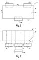
- Figures 6 and 7 show another alternative arrangement for the tubes on the vessel. This is known as the ladder arrangement.
- two tubes 14 are suspended close to the port side 8 and two tubes are suspended close to the starboard side 10.
- One port side tube 14a is located near the bow of the vessel and one port side tube 14b is located near the stern of the vessel.
- Both starboard side tubes are located amidships, the second starboard side tube 14d being suspended beneath the first starboard side tube 14c.
- Figures 10 and 11 show a tube 14 having a square cross section. Such a cross section gives the tube a greater drag through the water.
- the horizontal fins project from the side of the square tubes.
- the horizontal fins project from the base of the square tubes.
Landscapes
- Chemical & Material Sciences (AREA)
- Engineering & Computer Science (AREA)
- Combustion & Propulsion (AREA)
- Mechanical Engineering (AREA)
- Ocean & Marine Engineering (AREA)
- Earth Drilling (AREA)
- Filling Or Discharging Of Gas Storage Vessels (AREA)
- Bridges Or Land Bridges (AREA)
- Other Liquid Machine Or Engine Such As Wave Power Use (AREA)
- Processing Of Solid Wastes (AREA)
- Vibration Prevention Devices (AREA)
- Structures Of Non-Positive Displacement Pumps (AREA)
- Physical Or Chemical Processes And Apparatus (AREA)
- Toys (AREA)
- Control Of Position, Course, Altitude, Or Attitude Of Moving Bodies (AREA)
- Sampling And Sample Adjustment (AREA)
Abstract
Description
- The present invention relates to an apparatus and method for reducing motion of a floating vessel. In particular, but not exclusively, the invention relates to an apparatus and method for reducing the roll of a large floating vessel.
- It is well known that ships, barges and other floating platforms roll, pitch and heave at sea and that such motion is undesirable in many fields. For example, such motion may be particularly undesirable when loading and unloading to and from the vessel. This is particularly the case for vessels involved with the offshore oil and gas industries. In that application it is common to unload and load, from and to a stationary structure e.g. a deck supported on a jacket on the sea bed or from and to another vessel.
- Additionally, in the field of offshore gas and oil, the vessels may be extremely large so that, whilst the movement of the vessel is not very great when expressed in degrees of inclination, the movement at deck height is considerable, causing difficulties even in relatively calm conditions.
- There are many known systems which aim to reduce roll and/or pitch motion of floating vessels. There are some systems that have been designed for relatively small vessels. For example,
GB 2219973 - Another system which aims to reduce instability of a larger vessel is described in
US 5787832 . In that system, stabilizer assemblies are attached to the hull of the vessel. Each assembly includes an outrigger arm and a float arm which has a float attached to one end. The floats are in contact with the water surface at all times and the system works by increasing the effective width of the vessel so as to increase the natural period of its rolling/pitching motion. Each stabilizer assembly has to be attached to the vessel through a very strong fastening that has to bear very high loads.US 3407766 describes another system which aims to reduce the instability of a larger vessel by providing a stabilizing body below the vessel and connecting it by rigid struts such as steel I-beams which are able to transmit a force moment back to the vessel. A major drawback to an arrangement of this kind is the very considerable strength required of the struts in order to transmit force moment from the stabilizing body to the vessel. -
NL 1020053 - It is an object of the invention to provide an apparatus and method which avoids or mitigates the problems of known stabilizing systems described above.
- According to a first aspect of the invention, there is provided a vessel comprising a first stabilizer assembly and a second stabilizer assembly, each stabilizer assembly comprising:
- at least one submergible at least partially hollow body comprising at least one ballast tank; and
- suspending means for suspending the or each body below the vessel such that the or each body is fully submerged below the water line of the vessel, the first and second stabilizer assemblies being suspended from substantially opposite sides of the vessel, wherein the suspending means of the first stabiliser assembly is connected to the suspending means of the second stabiliser assembly.
- Such stabilizer assemblies can be installed in port or at sea and are able to be adapted to be used with any suitable vessel. Because they are at least partially hollow, they can be relatively large for a given mass and the suspending of the assemblies from the vessel can be accomplished relatively easily. Each stabilizer assembly is arranged to apply via the suspending means a downwardly directed force on the side of the vessel from which it is suspended when that side of the vessel moves upwards.
- Typically, one stabilizer assembly is suspended from the port side of the vessel and one stabilizer assembly is suspended from the starboard side of the vessel. This reduces the roll of the vessel. The invention is, however, applicable to any kind of vessel some of which may not have clearly defined port and starboard sides (or bow and stern ends). It should be understood, however, that what are referred to herein as the sides of the vessel are those parts of the vessel that rise and fall when the vessel undergoes a rocking motion. The term does not necessarily refer to the port and starboard sides of the vessel.
- Often the first stabilizer assembly will comprise a single submergible body but it may comprise:
- a first submergible at least partially hollow body and a second submergible at least partially hollow body; first suspending means for suspending the first body from the vessel; and
- second suspending means for suspending the second body from the first body.
- Similarly, the second stabilizer assembly will often comprise a single submergible body but it may comprise:
- a first submergible at least partially hollow body and a second submergible at least partially hollow body;
- first suspending means for suspending the first body from the vessel; and
- second suspending means for suspending the second body from the first body.
- The vessel may further comprise a third stabilizer assembly, the third stabilizer assembly comprising:
- at least one submergible at least partially hollow body; and
- suspending means for suspending the or each body from the vessel.
- In one embodiment, the first stabilizer assembly is suspended near the bow of the vessel on one side, the third stabilizer assembly is suspended near the stern of the vessel on said one side and the second stabilizer assembly is suspended amidships on the other side of the vessel.
- The above embodiments using three stabilizer assemblies are known as asymmetric arrangements.
- Like the first and second stabilizer assemblies, the third stabilizer assembly may comprise:
- a first submergible at least partially hollow body and a second submergible hollow body;
- first suspending means for suspending the first body from the vessel; and
- second suspending means for suspending the second body from the first body.
- The vessel may further comprise a fourth stabilizer assembly, the fourth stabilizer assembly comprising:
- at least one submergible at least partially hollow body; and
- suspending means for suspending the or each body from the vessel.
- The fourth stabilizer assembly may be suspended from the port or starboard side of the vessel.
- In one embodiment, the first stabilizer assembly is suspended near the bow of the vessel on one side, the second stabilizer assembly is suspended near the bow of the vessel on the other side, the third stabilizer assembly is suspended near the stern of the vessel on said one side and the fourth stabilizer assembly is suspended near the stern of the vessel on the other side.
- In another embodiment, the first stabilizer assembly is suspended near the bow of the vessel on one side, the second stabilizer assembly is suspended near the stern of the vessel on said one side and the third and fourth stabilizer assemblies are suspended amidships on the other side of the vessel.
- It will be understood that the assemblies may be arranged in any of a wide variety of configurations. If the submergible bodies of the assemblies are all of substantially the same size, then it may be advantageous for the same number of bodies to be provided on each side of the vessel.
- The reduction of vessel motion relies upon the suspending means being able to apply downwardly directed loads resisting upward movement and the suspending means is therefore advantageously capable of bearing high tension loads. Whilst the suspending means may be capable of bearing high compressive loads too, that is not necessary and it may be more economical and simple not to provide for that. Thus the suspending means may be capable of bearing tension loads of more than one hundred times the loads it is capable of bearing in compression, The suspending means may comprise elongate flexible members, for example, chains, ropes or cables. The or each body is preferably attached to the suspending means at a plurality of locations; for example an elongate body may be attached to a respective elongate flexible member in the region of each of the opposite ends of the body.
- Each body is preferably large and is also preferably elongate. Thus in a case where each body is elongate, it may have a cross-sectional area greater than 4 m2 and preferably greater than 10 m2. Each body may comprise one or more closed or closable spaces having a combined volume of more than 50 m3 and preferably more than 300 m3. The closed space or spaces are preferably sealed or sealable but they may alternatively allow some fluid transfer in and/or out of the space or spaces. In a case where the body is elongate it is preferably suspended with the longitudinal axis of the body substantially horizontal.
- Each body comprises at least one ballast tank. Preferably, each body comprises a plurality of ballast tanks, each separately ballastable. If the bodies are ballastable, the bodies can be suitably ballasted so that the rolling can be controlled to be dependent on the force and period of the waves. Thus, the amount of damping of the rolling motion can be adjusted according to the conditions. In addition, if it is required to unload or load from or to the vessel to or from another vessel, the amount of damping can be adjusted to bring the vessel into line with the other vessel so that unloading and loading is facilitated.
- Preferably, each stabilizer assembly further comprises at least one fin projecting from the or each body. The fins increase the drag on the bodies as they move through the water.
- The size and shape of the fins is variable. For example, the fins may be straight or curved. In one embodiment, the at least one fin is pivotable relative to the or each body to restrict movement of the body in one direction (upwardly through water) more than in another direction (downwardly). This is useful because it is often required that there is more drag on the bodies when they are moving vertically upward than when they are moving vertically downward and the fins can be pivotable accordingly. Alternatively, the fins can be shaped be so that there is more drag in one direction than in the other direction.
- Preferably, each body is substantially cylindrical and/or prism shaped. In one embodiment, the body is in the form of a tube.
- The body may have a round, and preferably a circular, cross section. Alternatively, the body may have a rectangular cross section, for example a square cross section. Alternatively, the body may have a triangular cross section.
- In one embodiment, one or both ends of the body are substantially conical. This is advantageous because it facilitates transport. The bodies may, for example, be attached to the vessel to be towed beneath the water line to the desired location, at which point they can be attached to the vessel at the appropriate points. Having conical ends facilitates towing. The bodies may alternatively have hemispherical or rounded ends or any other shape which facilitates towing.
- Consideration needs to be given to transferring loads from the suspending means to the vessel structure. Accordingly there is preferably provided a load transfer structure connected between the vessel structure and the suspending means for transferring loads from the suspending means to the vessel structure. In a preferred embodiment of the invention the load transfer structure is provided by one or more saddles for attaching to the vessel, to support the suspending means. The saddles may be attached at the edge of the deck of the vessel at the port or starboard side. The saddles may be attached when the vessel is in port or when the vessel is at sea. The saddles extend the width of the vessel so that the bodies are suspended from points which are slightly further apart than the width of the vessel itself.
- In the preferred embodiment of the invention it is only vertical loads from the suspending means that are to be transferred and it is therefore preferred that only vertical loads are arranged to be transferred from the suspending means to the vessel. That may result from the nature of the suspending means (for example if the suspending means is an elongate flexible member), or from the nature of a coupling.
- The suspending means of the first stabilizer assembly is connected to the suspending means of the second stabilizer assembly. That connection is preferably a structural connection made directly or indirectly. If made indirectly it is preferably made through an additional structure separate from the vessel structure.
- According to a second aspect of the invention, there is an apparatus for reducing vessel motion comprising a first stabilizer assembly and a second stabilizer assembly, each stabilizer assembly comprising:
- at least one submergible at least partially hollow body including at least one ballast tank; and
- suspending means for suspending the or each body from the vessel,
- the first and second stabilizer assemblies being suitable for locating at substantially opposite portions of the vessel wherein the suspending means of the first stabilizer assembly is connected to the suspending means of the second stabilizer assembly.
- Each body comprises at least one ballast tank. Preferably, each body comprises a plurality of ballast tanks, each separately ballastable.
- Preferably, each stabilizer assembly further comprises at least one fin projecting from each body. Even more preferably, the at least one fin is pivotable relative to each body to restrict movement of the body in one direction more than in another direction.
- Advantageously, each body is substantially cylindrical and/or prism shaped. In one embodiment, the body has a round, and preferably a circular, cross section. In another embodiment, the body has a rectangular cross section, for example a square cross section. In another embodiment, the body has a triangular cross section.
- One or both ends of the body may be substantially conical, hemispherical or rounded. This facilitates transport by towing.
- The apparatus may further comprise saddles for attaching to the vessel, to support the suspending means. The saddles may be attached at the edge of the deck of the vessel at the port or starboard side. The saddles may be attached when the vessel is in port or when the vessel is at sea. The saddles extend the width of the vessel so that the bodies are suspended from points which are slightly further apart than the width of the vessel itself. This further stabilizes the vessel.
- The suspending means of the first stabilizer assembly is connected to the suspending means of the second stabilizer assembly. That connection is preferably a structural connection made directly or indirectly. If made indirectly it is preferably made through an additional structure separate from the vessel structure.
- It should be understood that in the description above, where a feature is described with regard to one aspect of the invention, it may also where appropriate be employed in respect of another aspect of the invention. Thus, for example, the method of the fourth aspect of the invention may be employed with a vessel of any of the forms defined according to the first aspect of the invention.
- An embodiment of the invention will now be described with reference to the accompanying drawings of which:
- Figure 1
- is a plan view of a vessel including stabilizing apparatus according to the invention;
- Figure 2
- is a side elevation view of the vessel of
Figure 1 ; - Figure 3
- is a front elevation view of the vessel of
Figures 1 and 2 ; - Figure 4
- is a plan view of a vessel having a first alternative stabilizing arrangement;
- Figure 5
- is a side elevation view of the vessel of
Figure 4 ; - Figure 6
- is a plan view of a vessel having a second alternative stabilizing arrangement;
- Figure 7
- is a side elevation view of the vessel of
Figure 6 ; - Figure 8
- is a plan view of a stabilizing tube;
- Figure 9
- is a side elevation view of the tube of
Figure 8 ; - Figure 10
- is a cross sectional view of a stabilizing tube having an alternative construction;
- Figure 11
- is a cross sectional view of a stabilizing tube; having a second alternative construction;
- Figure 12
- is a cross sectional view of a stabilizing tube having a third alternative construction; and
- Figure 13
- is a plot showing the effect of the stabilizing arrangement on the degree and period of rolling motion.
-
Figures 1, 2 and 3 show avessel 2 having a stern 4, abow 6, aport side 8, astarboard side 10 and adeck 12. Suspended from the vessel are fourtubes 14, two tubes close to theport side 8 and two tubes close to thestarboard side 10. Oneport side tube 14a is located near the bow of the vessel. Oneport side tube 14b is located near the stern of the vessel. Onestarboard side tube 14c is located near the bow of the vessel. Onestarboard side tube 14d is located near the stern of the vessel. Eachtube 14 is suspended from the vessel by twochains 16. Thechains 16 fromopposite tubes deck 12. As shown in the drawings the tubes are arranged with their longitudinal axes horizontal. -
Saddles 18 located at the edge between thedeck 12 and theport side 8 and thedeck 12 and thestarboard side 10, support thechains 16. This ensures that thechains 16 remain clear of the sides of the vessel even when the vessel rolls a certain amount. - Each
tube 14 is substantially cylindrical. Each tube includes a number of ballast tanks (not shown) which can be separately ballasted and deballasted thus allowing the mass of thetubes 14 in the water to be controlled. Eachtube 14 also includes twohorizontal fins 22. Thehorizontal fins 22 impede movement at speed of thetubes 14 in the vertical direction. - As the vessel rolls, the
port side 8 and thestarboard side 10 alternately rise and fall. As theport side 8 rises, theport side tubes starboard side 10 rises, thestarboard side tubes vessel 2 is reduced; the degree of rolling is reduced and the period of the motion is increased i.e. the frequency is reduced. - The tubes, chains and saddles may be attached to the vessel in port or at sea.
- The diameter and length of each tube is variable to suit the application. The material used to construct the tube is variable and this will depend upon the desired mass of each tube. The mass of each tube affects the acceleration of the tubes through the water. The number of ballast tanks in each tube is variable and the tubes are designed to be ballastable on deck so that the tubes can easily be towed in the water to facilitate transport. The cross section of the tubes is also variable (see
Figures 10 to 12 ). The tubes may have conical ends in order to facilitate transport. The length of the chains is also variable. The size and shape of the fins is variable and the fins may be pivotable in relation to the tube such that, as the tube moves vertically upwards the fins project horizontally to impede the upwards motion, but as the tube moves vertically downwards the fins pivot inwards so as not to impede the downwards motion. The size and shape of the fins affect the speed of the tubes through the water. - In one embodiment, the tubes are 40m long, with conical ends, and 5m in diameter. Each tube weighs 200 tonnes and comprises ten separate ballast tanks. Each tube has two projecting 75 cm fins, which extend along all of the tube and cones. The tubes can be suspended 25m below the water line.
-
Figures 4 and 5 show an alternative arrangement for the tubes on the vessel. This is known as the asymmetric arrangement. In this case twotubes 14 are suspended close to theport side 8 and one tube is suspended close to thestarboard side 10. Oneport side tube 14a is located near the bow of the vessel and oneport side tube 14b is located near the stern of the vessel. Thestarboard side tube 14c is located amidships. Of course, there could alternatively be two tubes on the starboard side and only one tube on the port side. -
Figures 6 and 7 show another alternative arrangement for the tubes on the vessel. This is known as the ladder arrangement. In this case twotubes 14 are suspended close to theport side 8 and two tubes are suspended close to thestarboard side 10. Oneport side tube 14a is located near the bow of the vessel and oneport side tube 14b is located near the stern of the vessel. Both starboard side tubes are located amidships, the secondstarboard side tube 14d being suspended beneath the firststarboard side tube 14c. Of course, there could alternatively be two tubes amidships on the port side, one stern starboard side tube and one bow starboard side tube. - Alternative arrangements are also envisaged, which are not explicitly illustrated, for example a double ladder arrangement having two tubes amidships on the port side and two tubes amidships on the starboard side.
-
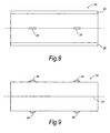
Figures 8 and 9 show thetubes 14 in more detail. Eachtube 14 has twohorizontal fins 22 projecting from thetube 14. Eachtube 14 also has liftingpoints 24 shown schematically inFigures 8 and 9 . On thetube 14 shown inFigure 9 there are fourlifting points 24, two on the upper side of the tube and two on the lower side. The two lifting points 24 on the upper side allow thechains 16 to be attached for suspending the tubes from the vessel. The two lifting points 24 on the lower side are only useful when the tube is used in the ladder arrangement shown inFigures 6 and 7 . However, in many cases, it is advantageous for all the tubes to have fourlifting points 24 so that the construction of every tube is the same and any tube can be used in any application. -
Figures 10 and 11 show atube 14 having a square cross section. Such a cross section gives the tube a greater drag through the water. InFigure 10 the horizontal fins project from the side of the square tubes. InFigure 11 , the horizontal fins project from the base of the square tubes. -
Figure 12 shows atube 14 having a triangular cross section. Such a cross section gives the tube increased drag when moving vertically upward but reduced drag when moving vertically downward. As the vessel rolls, the port side and the starboard side alternately rise and fall. As the port side falls, the tubes on the port side are required to move downwards through the water. It is therefore advantageous if there is as little drag in the downwards direction as possible. Conversely, as the port side rises, the tubes on the port side are required to resist movement upwards through the water. It is therefore advantageous if there is as much drag in the upwards direction as possible. - Other cross sectional shapes may also be envisaged and these shapes will have different effects on the speed and acceleration of the tubes in the water, as the vessel rolls.
- It is particularly advantageous if the size and shape of the tubes takes into account the use of the tubes in other applications. Additionally, the storage of the tubes should be considered. For example, in the field of offshore oil and gas, the tubes may be storable horizontally on the deck of a stationary structure, on a vessel or on shore. Alternatively, the tubes may be stored in the sea when they are not in use. They may, for example, be stored horizontally on the sea bed, preferably with a warning buoy floating on the sea above them, or a group of tubes may be rotated into upright positions, tied together and moored at sea in a floating arrangement with parts of the tubes projecting upwards above the surface and parts submerged below the surface.
- When considering the effect of the stabilizing apparatus on the rolling motion of the vessel, there are two factors to be considered: the frequency of the rolling motion and the amplitude of the rolling motion. The natural frequency of the rolling is dependent on the mass of the system, since, as the mass of the tubes increases, the natural period of the rolling motion of the vessel increases. The amplitude of the rolling is dependent on the damping forces applied to the system and as the damping force increases, the amplitude will decrease i.e. the amplitude is dependent on the geometry of the tubes. Thus, as the diameter of the tubes and the size of the fins increases, the amplitude of the rolling motion of the vessel decreases.
- Referring to
Figure 13 , the effect of the stabilizing apparatus can be seen very clearly.Figure 13 shows the amplitude of rolling as a function of the period of the applied wave motion. The x-axis shows the period in seconds and the y-axis the roll RAO in deg/m. The top plot is the base case i.e. the vessel without any stabilizing apparatus. It can be seen that the natural period of the vessel is close to 10 s. The middle plot is a middle case where the vessel is fitted with stabilizing apparatus in which the tubes have a diameter of 3 m and the fins project 500 mm. It can be seen that the natural period of the vessel is close to 11 s. The bottom plot is a further case where the vessel is fitted with stabilizing apparatus in which the tubes have a diameter of 5 m and the fins project 500 mm. It can be seen that the natural period of the vessel is close to 12 s. - Thus, it can be seen clearly from
Figure 13 that the effect of the stabilizing apparatus is to reduce the amplitude of the rolling motion of the vessel (i.e. the peak of the curves decreases) and to increase the period of the rolling motion of the vessel (i.e. the peak of the curves moves to the right in the x-direction). - The description above is somewhat simplified and, as previously mentioned, there are many other variables which will affect the amplitude and period of the rolling motion e.g. the cross-sectional shape of the tubes and the size and shape of the fins.
- Whilst certain specific embodiments of the invention have been described, it should be understood that many variations are possible. In particular, if the
tubes 14 are not in use stabilizing a vessel, they may be put to a variety of other uses. For example a tube may be floated with its longitudinal axis horizontal and used as a mooring buoy. Alternatively it may be used as a flotation tank for transporting a structure and may further be used, after appropriate ballasting, for raising a structure from the seabed or lowering a structure to the seabed.
Claims (13)
- A vessel (2) comprising a first stabilizer assembly and a second stabilizer assembly, each stabilizer assembly comprising :at least one submergible at least partially hollow body (14) comprising at least one ballast tank; andsuspending means (16) for suspending the or each body below the vessel such that the or each body is fully submerged below the water line of the vessel;the first and second stabilizer assemblies being suspended from substantially opposite sides of the vessel (2), wherein the suspending means of the first stabiliser assembly is connected to the suspending means of the second stabiliser assembly.
- A vessel (2) according to claim 1 wherein the first stabilizer assembly comprises:a first submergible at least partially hollow body and a second submergible at least partially hollow body;first suspending means for suspending the first body from the vessel; andsecond suspending means for suspending the second body from the first body.
- A vessel (2) according to claim 1 or claim 2 wherein the second stabilizer assembly comprises:a first submergible at least partially hollow body (14) and a second submergible at least partially hollow body (14);first suspending means for suspending the first body from the vessel; andsecond suspending means for suspending the second body from the first body.
- A vessel (2) according to any preceding claim wherein the suspending means (16) is capable of bearing tension loads of more that 100 times the loads it is capable of bearing in compression.
- A vessel according to claim 4 wherein the suspending means (16) comprises elongate flexible members.
- A vessel (2) according to any preceding claim wherein each stabilizer assembly further comprises at least one fin projecting from the or each body.
- A vessel (2) according to claim 6 wherein the at least one fin is pivotable relative to the or each body to restrict movement of the body upwardly through water more than downwardly.
- A vessel (2) according to any preceding claim, further comprising one or more saddles (18) for attaching to the vessel, to support the suspending means (16).
- A vessel (2) according to any preceding claim wherein the vessel comprises a deck and the suspending means of the first stabiliser assembly is connected to the suspending means of the second stabiliser assembly close to the centre of the deck.
- A vessel (2) according to any preceding claim, in which only vertical loads are arranged to be transferred from the suspending means (16) to the vessel.
- An apparatus for reducing vessel motion comprising a first stabilizer assembly and a second stabilizer assembly, each stabilizer assembly comprising:at least one submergible at least partially hollow body (14) including at least one ballast tank; andsuspending means (16) for suspending the or each body from the vessel, such that the or each body is fully submerged below the water line of the vessel,the first and second stabilizer assemblies being suitable for locating at substantially opposite portions of the vessel, wherein the suspending means of the first stabiliser assembly is connected to the suspending means of the second stabiliser assembly.
- An apparatus according to claim 11 wherein each stabilizer assembly further comprises at least one fin projecting from the or each body.
- An apparatus according to claim 12 wherein the at least one fin is pivotable relative to the or each body to restrict movement of the body through water in one direction more than in another direction.
Applications Claiming Priority (2)
| Application Number | Priority Date | Filing Date | Title |
|---|---|---|---|
| GBGB0323698.1A GB0323698D0 (en) | 2003-10-09 | 2003-10-09 | Apparatus and method for reducing motion of a floating vessel |
| PCT/GB2004/004266 WO2005035355A1 (en) | 2003-10-09 | 2004-10-08 | Apparatus and method for reducing motion of a floating vessel |
Publications (2)
| Publication Number | Publication Date |
|---|---|
| EP1670676A1 EP1670676A1 (en) | 2006-06-21 |
| EP1670676B1 true EP1670676B1 (en) | 2010-08-04 |
Family
ID=29433607
Family Applications (1)
| Application Number | Title | Priority Date | Filing Date |
|---|---|---|---|
| EP04768800A Expired - Lifetime EP1670676B1 (en) | 2003-10-09 | 2004-10-08 | Apparatus and method for reducing motion of a floating vessel |
Country Status (16)
| Country | Link |
|---|---|
| US (1) | US8136465B2 (en) |
| EP (1) | EP1670676B1 (en) |
| CN (1) | CN100584692C (en) |
| AT (1) | ATE476354T1 (en) |
| AU (1) | AU2004280289B2 (en) |
| BR (1) | BRPI0415128A (en) |
| CA (1) | CA2538492C (en) |
| DE (1) | DE602004028499D1 (en) |
| DK (1) | DK1670676T3 (en) |
| EG (1) | EG24419A (en) |
| ES (1) | ES2349538T3 (en) |
| GB (1) | GB0323698D0 (en) |
| NO (1) | NO336635B1 (en) |
| PT (1) | PT1670676E (en) |
| RU (1) | RU2433937C2 (en) |
| WO (1) | WO2005035355A1 (en) |
Families Citing this family (10)
| Publication number | Priority date | Publication date | Assignee | Title |
|---|---|---|---|---|
| CN102079364B (en) * | 2009-11-27 | 2013-04-10 | 三一电气有限责任公司 | Wind turbine installation vessel and gravity center adjusting devices for same |
| US8635967B1 (en) * | 2010-09-23 | 2014-01-28 | The United States of America as represented by the Secretarey of the Navy | Ballast structure for reducing water-mixing in ships |
| NL2006280C2 (en) | 2011-02-22 | 2012-08-24 | Seaway Heavy Lifting Engineering B V | Vessel comprising a stabilizing system. |
| CN103057671B (en) * | 2011-10-19 | 2015-09-23 | 徐际长 | Marine facility stabilizer of floating |
| CN103963774B (en) * | 2013-02-06 | 2017-02-08 | 上海交通大学 | Lateral-drift-resistant damping system of all-hovering hovercraft |
| CN103144748A (en) * | 2013-03-21 | 2013-06-12 | 徐积勉 | Naval vessel bottom flexible heavy punch stabilization device capable of improving naval vessel seakeeping performance and firing accuracy |
| ES2555500B1 (en) * | 2014-05-27 | 2016-12-13 | Sea Wind Towers Sl | Floating work and installation procedure |
| KR102157704B1 (en) * | 2018-11-13 | 2020-09-18 | 이태호 | Position stabilization device for ship |
| PE20231004A1 (en) * | 2020-08-31 | 2023-06-27 | De Krassnokutski Alexei Egmar Krass | WATER EXCAVATOR |
| NO347611B1 (en) * | 2021-01-04 | 2024-01-29 | North Innovation As | A system for motion damping of a floating marine structure, an arrangement, a method and use of such system |
Family Cites Families (66)
| Publication number | Priority date | Publication date | Assignee | Title |
|---|---|---|---|---|
| US83420A (en) | 1868-10-27 | Improvement in ballasting- vessels | ||
| US1299186A (en) * | 1918-11-18 | 1919-04-01 | Tatsujiro Imaizumi | Ship-stabilizer. |
| SU27301A1 (en) * | 1929-09-13 | 1932-07-31 | И.И. Сидоров | Device for communicating stability of the boat on the water |
| GB380051A (en) | 1930-05-30 | 1932-09-01 | Gesellschaft Fuer Elek App | Improvements in and relating to means for controlling the liquid masses of tanks forcompensating the rolling of ships |
| US2561539A (en) * | 1949-10-19 | 1951-07-24 | Eugene R Seward | Submersible marine stabilizer for boats |
| US2895300A (en) * | 1953-07-22 | 1959-07-21 | John T Hayward | Method and apparatus for stabilizing submersible vessels |
| US3064613A (en) | 1961-04-21 | 1962-11-20 | Hubick Leonard | Stabilizer for boats |
| US3263641A (en) * | 1964-09-15 | 1966-08-02 | Robert F Patterson | Anchoring structure |
| US3407766A (en) * | 1966-09-22 | 1968-10-29 | Pike Corp Of America | Stabilized floating structure |
| USRE29167E (en) | 1968-09-04 | 1977-04-05 | Santa Fe International Corporation | Twin hull variable draft drilling vessel |
| US3568620A (en) * | 1969-02-26 | 1971-03-09 | Donald W Douglas | Roll and pitch suppressor for floating marine structures |
| US3978814A (en) | 1973-07-05 | 1976-09-07 | Willyard James C | Air nozzle controlled marine propulsion system |
| US4003473A (en) | 1974-08-30 | 1977-01-18 | Ryan Ramp, Inc. | Combined marine ramp transfer and mooring system |
| US3952680A (en) | 1974-09-30 | 1976-04-27 | Griffin Edward N | Roll stabilizer for vessels at rest |
| US4070982A (en) | 1975-03-17 | 1978-01-31 | Willyard James C | Cylinder-driven marine propulsion system |
| US3965837A (en) | 1975-05-01 | 1976-06-29 | Brown & Root, Inc. | Vessel having improved wave response characteristics |
| US3986471A (en) | 1975-07-28 | 1976-10-19 | Haselton Frederick R | Semi-submersible vessels |
| US4040265A (en) | 1976-02-06 | 1977-08-09 | Marine Engineering Systems, Inc. | Mobile offshore platform |
| US4176614A (en) | 1976-10-20 | 1979-12-04 | Seatek Corporation | Control force tank and method for stabilizing floating vessels |
| US4140074A (en) | 1977-04-15 | 1979-02-20 | Seatek | System for stabilizing a floating vessel |
| NO143139C (en) * | 1978-01-17 | 1981-01-07 | Odd Havre | PROCEDURE FOR TRANSFER OF A FLUID FROM A STATION ON THE SEA BATH TO A VESSEL OR OTHERWISE AND A DEVICE FOR EXECUTING THE PROCEDURE |
| US4232903A (en) | 1978-12-28 | 1980-11-11 | Lockheed Missiles & Space Co., Inc. | Ocean mining system and process |
| US4279047A (en) | 1979-01-18 | 1981-07-21 | Bluewater Terminal Systems N.V. | Fluid transfer buoy |
| SE419741B (en) * | 1979-03-09 | 1981-08-24 | Navire Carogo Gear Internation | MOVEMENT BODY PROVIDED BY CORBANE PLANE TO DISCOVER TURNING TRENDS CAUSED BY PASSING LOADS |
| US4366766A (en) | 1979-04-09 | 1983-01-04 | Bergman Gunnar B | System for stabilizing a floating vessel |
| JPS55148681A (en) * | 1979-05-08 | 1980-11-19 | Fudo Constr Co Ltd | Underwater anchor device |
| US4276851A (en) | 1979-08-10 | 1981-07-07 | Coleman Jess A | Underwater cruise device |
| US4261278A (en) | 1979-12-17 | 1981-04-14 | Gaudin George C | Gyro-controlled pitch stabilizing system |
| US4326479A (en) | 1980-04-17 | 1982-04-27 | Masasuke Kawasaki | Movable skeg for non-propelled barges |
| US4441448A (en) | 1980-07-25 | 1984-04-10 | Hillberg Ernest T | Controlled mooring |
| US4458619A (en) | 1981-03-13 | 1984-07-10 | Seatek Corporation | Apparatus for reducing roll and pitch motions of floating vessels |
| US4435108A (en) | 1981-08-11 | 1984-03-06 | Sedco, Inc. | Method of installing sub-sea templates |
| NL8202334A (en) * | 1982-06-09 | 1982-08-02 | Single Buoy Moorings | DEVICE FOR MAINTAINING A FLOATING BODY IN PLACE WITH RESPECT TO ANOTHER BODY. |
| US4576520A (en) | 1983-02-07 | 1986-03-18 | Chevron Research Company | Motion damping apparatus |
| US4666411A (en) | 1984-08-07 | 1987-05-19 | Richard Silvester | Thrust augmenter |
| JPS6177591A (en) | 1984-09-26 | 1986-04-21 | Nippon Kokan Kk <Nkk> | Hull heel reduction/sway damping device |
| GB8518001D0 (en) | 1985-07-17 | 1985-08-21 | British Aerospace | Open sea transfer of fluids |
| GB2219973A (en) | 1988-06-28 | 1989-12-28 | Alan Robert Macdonald | Stabilising a water borne craft |
| CA1321827C (en) | 1988-12-19 | 1993-08-31 | Bruce A. Armstrong | Hydrophones and similar devices |
| US5072579A (en) | 1990-04-20 | 1991-12-17 | Innerspace Corporation | Marine vessel thruster |
| US5095839A (en) | 1990-10-09 | 1992-03-17 | Scott G. Nettleman | Stabilizer for boats and the like |
| US5144904A (en) | 1991-02-28 | 1992-09-08 | Ocean Torque Patent Pty. Ltd. | Stabilizing apparatus |
| US5215024A (en) | 1992-04-15 | 1993-06-01 | The United States Of America As Represented By The Secretary Of The Navy | Vessel-capturing berthing facility incorporating relative motion-mitigating apparatus |
| US5237947A (en) * | 1992-08-03 | 1993-08-24 | The United States Of America As Represented By The Secretary Of The Navy | Variable draft hull |
| DE69409975D1 (en) | 1993-01-06 | 1998-06-10 | Cape Fear Dredge Co | Method and device for removing materials from a body of water by means of a water flow |
| GB2286373B (en) | 1994-02-08 | 1998-02-04 | Dale Vernon Astley | Trimming device for a water borne vessel |
| US5558036A (en) | 1995-01-17 | 1996-09-24 | Skarhar, Inc. | Integrated tug/barge system with riding pusher boat |
| JPH0971293A (en) | 1995-09-08 | 1997-03-18 | Mitsui Eng & Shipbuild Co Ltd | Floating body shaker |
| US5787832A (en) | 1996-02-12 | 1998-08-04 | Spinka; Harold | Method and apparatus to stabilize marine vessels |
| DE29613752U1 (en) * | 1996-08-08 | 1996-10-10 | Uhl, Herbert, 77746 Schutterwald | Device for reducing or dampening undesirable ship movements for ships at anchor |
| FR2769578B1 (en) | 1997-10-13 | 2000-07-07 | Yvon Julian | DEVICE FOR STABILIZING THE PLATE OF A VESSEL IN AN ANCHORING OR DRIFT SITUATION |
| US6059236A (en) | 1998-06-19 | 2000-05-09 | General Atomics | Tangential force panel for active flow control of a conductive fluid |
| US6073573A (en) * | 1998-09-24 | 2000-06-13 | Gruber; Matthew | Floating multi-unit dwelling |
| US6655312B1 (en) * | 1999-08-09 | 2003-12-02 | Single Buoy Moorings Inc. | Active semi-weathervaning anchoring system |
| US6164230A (en) | 1999-08-20 | 2000-12-26 | The United States Of America As Represented By The Secretary Of The Navy | Passive system for mitigation of thruster wake deficit |
| US6293216B1 (en) | 1999-11-16 | 2001-09-25 | Bruce R. Barsumian | Surface effect ship (SES) hull configuration having improved high speed performance and handling characteristics |
| NO313585B1 (en) | 1999-11-30 | 2002-10-28 | Simon Moekster Shipping As | Support vessel for launching and intake / salvage of lifeboats and lifeboats |
| US6257165B1 (en) * | 1999-12-20 | 2001-07-10 | Allen Danos, Jr. | Vessel with movable deck and method |
| WO2001051345A1 (en) | 2000-01-07 | 2001-07-19 | Fmc Corporation | Mooring systems with active force reacting systems and passive damping |
| US6357378B1 (en) | 2000-02-12 | 2002-03-19 | Richard J. Hile | Watercraft mooring system |
| CN2457029Y (en) * | 2000-08-10 | 2001-10-31 | 宋广庆 | Anti-shipwreck and rock-reducing device for ship |
| JP2002068079A (en) | 2000-08-24 | 2002-03-08 | Yoshihiro Suda | Active anti-rolling device |
| JP4931272B2 (en) | 2000-11-15 | 2012-05-16 | 株式会社アイ・エイチ・アイ マリンユナイテッド | Rolling reduction structure of box-shaped floating body |
| JP2003034289A (en) | 2001-07-19 | 2003-02-04 | Mitsubishi Heavy Ind Ltd | Floating body reduced in rolling |
| US6789490B2 (en) | 2002-02-19 | 2004-09-14 | Lockheed Martin Corporation | Ship constructions for achieving stability at high speed through the use of multiple, low wave-making resistance, submerged hullform pods and control fins |
| NL1020053C1 (en) | 2002-02-25 | 2003-08-27 | Ver Bedrijven Van Den Berg Hee | Stabilizing construction, for floating objects, e.g. drilling or exploration platforms, comprises ballast tubes pivotally suspended from floating object |
-
2003
- 2003-10-09 GB GBGB0323698.1A patent/GB0323698D0/en not_active Ceased
-
2004
- 2004-10-08 DE DE602004028499T patent/DE602004028499D1/en not_active Expired - Lifetime
- 2004-10-08 BR BRPI0415128-3A patent/BRPI0415128A/en active Search and Examination
- 2004-10-08 CN CN200480027951A patent/CN100584692C/en not_active Expired - Fee Related
- 2004-10-08 PT PT04768800T patent/PT1670676E/en unknown
- 2004-10-08 RU RU2006115837/11A patent/RU2433937C2/en not_active IP Right Cessation
- 2004-10-08 AT AT04768800T patent/ATE476354T1/en not_active IP Right Cessation
- 2004-10-08 DK DK04768800.7T patent/DK1670676T3/en active
- 2004-10-08 AU AU2004280289A patent/AU2004280289B2/en not_active Ceased
- 2004-10-08 ES ES04768800T patent/ES2349538T3/en not_active Expired - Lifetime
- 2004-10-08 EP EP04768800A patent/EP1670676B1/en not_active Expired - Lifetime
- 2004-10-08 WO PCT/GB2004/004266 patent/WO2005035355A1/en not_active Ceased
- 2004-10-08 US US10/574,968 patent/US8136465B2/en not_active Expired - Fee Related
- 2004-10-08 CA CA2538492A patent/CA2538492C/en not_active Expired - Fee Related
-
2006
- 2006-05-08 NO NO20062055A patent/NO336635B1/en not_active IP Right Cessation
-
2007
- 2007-04-05 EG EGNA2006000326 patent/EG24419A/en active
Also Published As
| Publication number | Publication date |
|---|---|
| US20070175373A1 (en) | 2007-08-02 |
| CA2538492C (en) | 2012-04-24 |
| EP1670676A1 (en) | 2006-06-21 |
| BRPI0415128A (en) | 2006-11-28 |
| CA2538492A1 (en) | 2005-04-21 |
| EG24419A (en) | 2009-05-25 |
| CN100584692C (en) | 2010-01-27 |
| RU2433937C2 (en) | 2011-11-20 |
| DK1670676T3 (en) | 2010-10-25 |
| DE602004028499D1 (en) | 2010-09-16 |
| ATE476354T1 (en) | 2010-08-15 |
| US8136465B2 (en) | 2012-03-20 |
| AU2004280289B2 (en) | 2010-04-22 |
| CN1856427A (en) | 2006-11-01 |
| RU2006115837A (en) | 2007-11-20 |
| GB0323698D0 (en) | 2003-11-12 |
| PT1670676E (en) | 2010-11-03 |
| ES2349538T3 (en) | 2011-01-04 |
| AU2004280289A1 (en) | 2005-04-21 |
| NO20062055L (en) | 2006-07-06 |
| WO2005035355A1 (en) | 2005-04-21 |
| NO336635B1 (en) | 2015-10-12 |
Similar Documents
| Publication | Publication Date | Title |
|---|---|---|
| CN113581395B (en) | Semi-submersible floating wind turbine with T-shaped buoy | |
| EP1339922B1 (en) | Heave suppressed offshore drilling and production platform | |
| US6899492B1 (en) | Jacket frame floating structures with buoyancy capsules | |
| US8387550B2 (en) | Offshore floating platform with motion damper columns | |
| KR101771907B1 (en) | Offshore buoyant drilling, production, storage and offloading structure | |
| US3224401A (en) | Stabilized floating drilling platform | |
| US8291849B2 (en) | Drag-inducing stabilizer plates with damping apertures | |
| US4983073A (en) | Column stabilized platform with improved heave motion | |
| US6942427B1 (en) | Column-stabilized floating structure with telescopic keel tank for offshore applications and method of installation | |
| JPH02106488A (en) | Method and device for stabilizing marine platform | |
| US3160135A (en) | Stabilizing system for floating platform | |
| AU2004280289B2 (en) | Apparatus and method for reducing motion of a floating vessel | |
| US20020139286A1 (en) | Heave-damped caisson vessel | |
| US8752496B2 (en) | Semi-submersible vessel, method for operating a semi-submersible vessel and method for manufacturing a semi-submersible vessel | |
| US7484470B2 (en) | Soft quay mooring system | |
| WO1984001554A1 (en) | Floating, semi-submersible structure | |
| US4834014A (en) | Floating platform structure | |
| CN218806417U (en) | Floating platform suitable for shallow water floating transportation and deep water positioning | |
| MXPA06003934A (en) | Apparatus and method for reducing motion of a floating vessel | |
| SE2330189A1 (en) | Platform system | |
| KR20100033994A (en) | Floating structure for reducing rolling and heaving | |
| WO2002044011A2 (en) | Offshor platform for hydrocarbon production and storage | |
| NO842470L (en) | LIQUID HALF-SINK CONSTRUCTION |
Legal Events
| Date | Code | Title | Description |
|---|---|---|---|
| PUAI | Public reference made under article 153(3) epc to a published international application that has entered the european phase |
Free format text: ORIGINAL CODE: 0009012 |
|
| 17P | Request for examination filed |
Effective date: 20060330 |
|
| AK | Designated contracting states |
Kind code of ref document: A1 Designated state(s): AT BE BG CH CY CZ DE DK EE ES FI FR GB GR HU IE IT LI LU MC NL PL PT RO SE SI SK TR |
|
| DAX | Request for extension of the european patent (deleted) | ||
| 17Q | First examination report despatched |
Effective date: 20090130 |
|
| GRAP | Despatch of communication of intention to grant a patent |
Free format text: ORIGINAL CODE: EPIDOSNIGR1 |
|
| GRAS | Grant fee paid |
Free format text: ORIGINAL CODE: EPIDOSNIGR3 |
|
| GRAA | (expected) grant |
Free format text: ORIGINAL CODE: 0009210 |
|
| AK | Designated contracting states |
Kind code of ref document: B1 Designated state(s): AT BE BG CH CY CZ DE DK EE ES FI FR GB GR HU IE IT LI LU MC NL PL PT RO SE SI SK TR |
|
| REG | Reference to a national code |
Ref country code: GB Ref legal event code: FG4D |
|
| REG | Reference to a national code |
Ref country code: CH Ref legal event code: EP |
|
| REG | Reference to a national code |
Ref country code: IE Ref legal event code: FG4D |
|
| REF | Corresponds to: |
Ref document number: 602004028499 Country of ref document: DE Date of ref document: 20100916 Kind code of ref document: P |
|
| REG | Reference to a national code |
Ref country code: DK Ref legal event code: T3 |
|
| REG | Reference to a national code |
Ref country code: PT Ref legal event code: SC4A Free format text: AVAILABILITY OF NATIONAL TRANSLATION Effective date: 20101026 |
|
| REG | Reference to a national code |
Ref country code: NL Ref legal event code: T3 |
|
| REG | Reference to a national code |
Ref country code: ES Ref legal event code: FG2A Effective date: 20101221 |
|
| PG25 | Lapsed in a contracting state [announced via postgrant information from national office to epo] |
Ref country code: AT Free format text: LAPSE BECAUSE OF FAILURE TO SUBMIT A TRANSLATION OF THE DESCRIPTION OR TO PAY THE FEE WITHIN THE PRESCRIBED TIME-LIMIT Effective date: 20100804 Ref country code: FI Free format text: LAPSE BECAUSE OF FAILURE TO SUBMIT A TRANSLATION OF THE DESCRIPTION OR TO PAY THE FEE WITHIN THE PRESCRIBED TIME-LIMIT Effective date: 20100804 |
|
| PG25 | Lapsed in a contracting state [announced via postgrant information from national office to epo] |
Ref country code: PL Free format text: LAPSE BECAUSE OF FAILURE TO SUBMIT A TRANSLATION OF THE DESCRIPTION OR TO PAY THE FEE WITHIN THE PRESCRIBED TIME-LIMIT Effective date: 20100804 Ref country code: CY Free format text: LAPSE BECAUSE OF FAILURE TO SUBMIT A TRANSLATION OF THE DESCRIPTION OR TO PAY THE FEE WITHIN THE PRESCRIBED TIME-LIMIT Effective date: 20100804 Ref country code: BG Free format text: LAPSE BECAUSE OF FAILURE TO SUBMIT A TRANSLATION OF THE DESCRIPTION OR TO PAY THE FEE WITHIN THE PRESCRIBED TIME-LIMIT Effective date: 20101104 Ref country code: SI Free format text: LAPSE BECAUSE OF FAILURE TO SUBMIT A TRANSLATION OF THE DESCRIPTION OR TO PAY THE FEE WITHIN THE PRESCRIBED TIME-LIMIT Effective date: 20100804 |
|
| PG25 | Lapsed in a contracting state [announced via postgrant information from national office to epo] |
Ref country code: GR Free format text: LAPSE BECAUSE OF FAILURE TO SUBMIT A TRANSLATION OF THE DESCRIPTION OR TO PAY THE FEE WITHIN THE PRESCRIBED TIME-LIMIT Effective date: 20101105 Ref country code: BE Free format text: LAPSE BECAUSE OF FAILURE TO SUBMIT A TRANSLATION OF THE DESCRIPTION OR TO PAY THE FEE WITHIN THE PRESCRIBED TIME-LIMIT Effective date: 20100804 Ref country code: SE Free format text: LAPSE BECAUSE OF FAILURE TO SUBMIT A TRANSLATION OF THE DESCRIPTION OR TO PAY THE FEE WITHIN THE PRESCRIBED TIME-LIMIT Effective date: 20100804 |
|
| REG | Reference to a national code |
Ref country code: DE Ref legal event code: R097 Ref document number: 602004028499 Country of ref document: DE |
|
| PG25 | Lapsed in a contracting state [announced via postgrant information from national office to epo] |
Ref country code: SK Free format text: LAPSE BECAUSE OF FAILURE TO SUBMIT A TRANSLATION OF THE DESCRIPTION OR TO PAY THE FEE WITHIN THE PRESCRIBED TIME-LIMIT Effective date: 20100804 Ref country code: MC Free format text: LAPSE BECAUSE OF NON-PAYMENT OF DUE FEES Effective date: 20101031 Ref country code: EE Free format text: LAPSE BECAUSE OF FAILURE TO SUBMIT A TRANSLATION OF THE DESCRIPTION OR TO PAY THE FEE WITHIN THE PRESCRIBED TIME-LIMIT Effective date: 20100804 Ref country code: RO Free format text: LAPSE BECAUSE OF FAILURE TO SUBMIT A TRANSLATION OF THE DESCRIPTION OR TO PAY THE FEE WITHIN THE PRESCRIBED TIME-LIMIT Effective date: 20100804 Ref country code: CZ Free format text: LAPSE BECAUSE OF FAILURE TO SUBMIT A TRANSLATION OF THE DESCRIPTION OR TO PAY THE FEE WITHIN THE PRESCRIBED TIME-LIMIT Effective date: 20100804 |
|
| REG | Reference to a national code |
Ref country code: CH Ref legal event code: PL |
|
| PLBE | No opposition filed within time limit |
Free format text: ORIGINAL CODE: 0009261 |
|
| STAA | Information on the status of an ep patent application or granted ep patent |
Free format text: STATUS: NO OPPOSITION FILED WITHIN TIME LIMIT |
|
| 26N | No opposition filed |
Effective date: 20110506 |
|
| PG25 | Lapsed in a contracting state [announced via postgrant information from national office to epo] |
Ref country code: LI Free format text: LAPSE BECAUSE OF NON-PAYMENT OF DUE FEES Effective date: 20101031 Ref country code: CH Free format text: LAPSE BECAUSE OF NON-PAYMENT OF DUE FEES Effective date: 20101031 |
|
| REG | Reference to a national code |
Ref country code: DE Ref legal event code: R119 Ref document number: 602004028499 Country of ref document: DE Effective date: 20110502 |
|
| PG25 | Lapsed in a contracting state [announced via postgrant information from national office to epo] |
Ref country code: IE Free format text: LAPSE BECAUSE OF NON-PAYMENT OF DUE FEES Effective date: 20101008 |
|
| PG25 | Lapsed in a contracting state [announced via postgrant information from national office to epo] |
Ref country code: LU Free format text: LAPSE BECAUSE OF NON-PAYMENT OF DUE FEES Effective date: 20101008 Ref country code: HU Free format text: LAPSE BECAUSE OF FAILURE TO SUBMIT A TRANSLATION OF THE DESCRIPTION OR TO PAY THE FEE WITHIN THE PRESCRIBED TIME-LIMIT Effective date: 20110205 |
|
| PG25 | Lapsed in a contracting state [announced via postgrant information from national office to epo] |
Ref country code: TR Free format text: LAPSE BECAUSE OF FAILURE TO SUBMIT A TRANSLATION OF THE DESCRIPTION OR TO PAY THE FEE WITHIN THE PRESCRIBED TIME-LIMIT Effective date: 20100804 |
|
| PG25 | Lapsed in a contracting state [announced via postgrant information from national office to epo] |
Ref country code: DE Free format text: LAPSE BECAUSE OF NON-PAYMENT OF DUE FEES Effective date: 20110502 |
|
| REG | Reference to a national code |
Ref country code: PT Ref legal event code: PC4A Owner name: SAIPEM LIMITED, GB Effective date: 20150402 |
|
| REG | Reference to a national code |
Ref country code: GB Ref legal event code: 732E Free format text: REGISTERED BETWEEN 20150409 AND 20150415 |
|
| REG | Reference to a national code |
Ref country code: ES Ref legal event code: PC2A Owner name: SAIPEM LIMITED Effective date: 20150601 |
|
| REG | Reference to a national code |
Ref country code: FR Ref legal event code: TP Owner name: SAIPEM LIMITED, GB Effective date: 20150703 |
|
| REG | Reference to a national code |
Ref country code: FR Ref legal event code: PLFP Year of fee payment: 12 |
|
| PGFP | Annual fee paid to national office [announced via postgrant information from national office to epo] |
Ref country code: ES Payment date: 20150915 Year of fee payment: 12 |
|
| PGFP | Annual fee paid to national office [announced via postgrant information from national office to epo] |
Ref country code: FR Payment date: 20150908 Year of fee payment: 12 |
|
| PGFP | Annual fee paid to national office [announced via postgrant information from national office to epo] |
Ref country code: DK Payment date: 20151012 Year of fee payment: 12 |
|
| PGFP | Annual fee paid to national office [announced via postgrant information from national office to epo] |
Ref country code: GB Payment date: 20151007 Year of fee payment: 12 Ref country code: IT Payment date: 20151026 Year of fee payment: 12 |
|
| PGFP | Annual fee paid to national office [announced via postgrant information from national office to epo] |
Ref country code: NL Payment date: 20151012 Year of fee payment: 12 Ref country code: PT Payment date: 20151007 Year of fee payment: 12 |
|
| REG | Reference to a national code |
Ref country code: DK Ref legal event code: EBP Effective date: 20161031 |
|
| REG | Reference to a national code |
Ref country code: NL Ref legal event code: MM Effective date: 20161101 |
|
| GBPC | Gb: european patent ceased through non-payment of renewal fee |
Effective date: 20161008 |
|
| REG | Reference to a national code |
Ref country code: FR Ref legal event code: ST Effective date: 20170630 |
|
| PG25 | Lapsed in a contracting state [announced via postgrant information from national office to epo] |
Ref country code: FR Free format text: LAPSE BECAUSE OF NON-PAYMENT OF DUE FEES Effective date: 20161102 Ref country code: GB Free format text: LAPSE BECAUSE OF NON-PAYMENT OF DUE FEES Effective date: 20161008 |
|
| PG25 | Lapsed in a contracting state [announced via postgrant information from national office to epo] |
Ref country code: NL Free format text: LAPSE BECAUSE OF NON-PAYMENT OF DUE FEES Effective date: 20161101 Ref country code: PT Free format text: LAPSE BECAUSE OF NON-PAYMENT OF DUE FEES Effective date: 20170410 |
|
| PG25 | Lapsed in a contracting state [announced via postgrant information from national office to epo] |
Ref country code: IT Free format text: LAPSE BECAUSE OF NON-PAYMENT OF DUE FEES Effective date: 20161008 |
|
| PG25 | Lapsed in a contracting state [announced via postgrant information from national office to epo] |
Ref country code: DK Free format text: LAPSE BECAUSE OF NON-PAYMENT OF DUE FEES Effective date: 20161031 |
|
| PG25 | Lapsed in a contracting state [announced via postgrant information from national office to epo] |
Ref country code: ES Free format text: LAPSE BECAUSE OF NON-PAYMENT OF DUE FEES Effective date: 20161009 |
|
| REG | Reference to a national code |
Ref country code: ES Ref legal event code: FD2A Effective date: 20181126 |