EP1670012A2 - Push-on switch - Google Patents
Push-on switch Download PDFInfo
- Publication number
- EP1670012A2 EP1670012A2 EP05111372A EP05111372A EP1670012A2 EP 1670012 A2 EP1670012 A2 EP 1670012A2 EP 05111372 A EP05111372 A EP 05111372A EP 05111372 A EP05111372 A EP 05111372A EP 1670012 A2 EP1670012 A2 EP 1670012A2
- Authority
- EP
- European Patent Office
- Prior art keywords
- movable contact
- contact
- leg
- lower movable
- upper face
- Prior art date
- Legal status (The legal status is an assumption and is not a legal conclusion. Google has not performed a legal analysis and makes no representation as to the accuracy of the status listed.)
- Granted
Links
Images

Classifications
-
- H—ELECTRICITY
- H01—ELECTRIC ELEMENTS
- H01H—ELECTRIC SWITCHES; RELAYS; SELECTORS; EMERGENCY PROTECTIVE DEVICES
- H01H13/00—Switches having rectilinearly-movable operating part or parts adapted for pushing or pulling in one direction only, e.g. push-button switch
- H01H13/70—Switches having rectilinearly-movable operating part or parts adapted for pushing or pulling in one direction only, e.g. push-button switch having a plurality of operating members associated with different sets of contacts, e.g. keyboard
- H01H13/78—Switches having rectilinearly-movable operating part or parts adapted for pushing or pulling in one direction only, e.g. push-button switch having a plurality of operating members associated with different sets of contacts, e.g. keyboard characterised by the contacts or the contact sites
- H01H13/807—Switches having rectilinearly-movable operating part or parts adapted for pushing or pulling in one direction only, e.g. push-button switch having a plurality of operating members associated with different sets of contacts, e.g. keyboard characterised by the contacts or the contact sites characterised by the spatial arrangement of the contact sites, e.g. superimposed sites
-
- H—ELECTRICITY
- H01—ELECTRIC ELEMENTS
- H01H—ELECTRIC SWITCHES; RELAYS; SELECTORS; EMERGENCY PROTECTIVE DEVICES
- H01H13/00—Switches having rectilinearly-movable operating part or parts adapted for pushing or pulling in one direction only, e.g. push-button switch
- H01H13/02—Details
- H01H13/26—Snap-action arrangements depending upon deformation of elastic members
- H01H13/48—Snap-action arrangements depending upon deformation of elastic members using buckling of disc springs
-
- H—ELECTRICITY
- H01—ELECTRIC ELEMENTS
- H01H—ELECTRIC SWITCHES; RELAYS; SELECTORS; EMERGENCY PROTECTIVE DEVICES
- H01H13/00—Switches having rectilinearly-movable operating part or parts adapted for pushing or pulling in one direction only, e.g. push-button switch
- H01H13/50—Switches having rectilinearly-movable operating part or parts adapted for pushing or pulling in one direction only, e.g. push-button switch having a single operating member
- H01H13/64—Switches having rectilinearly-movable operating part or parts adapted for pushing or pulling in one direction only, e.g. push-button switch having a single operating member wherein the switch has more than two electrically distinguishable positions, e.g. multi-position push-button switches
-
- H—ELECTRICITY
- H01—ELECTRIC ELEMENTS
- H01H—ELECTRIC SWITCHES; RELAYS; SELECTORS; EMERGENCY PROTECTIVE DEVICES
- H01H2215/00—Tactile feedback
- H01H2215/004—Collapsible dome or bubble
-
- H—ELECTRICITY
- H01—ELECTRIC ELEMENTS
- H01H—ELECTRIC SWITCHES; RELAYS; SELECTORS; EMERGENCY PROTECTIVE DEVICES
- H01H2225/00—Switch site location
- H01H2225/002—Switch site location superimposed
-
- H—ELECTRICITY
- H01—ELECTRIC ELEMENTS
- H01H—ELECTRIC SWITCHES; RELAYS; SELECTORS; EMERGENCY PROTECTIVE DEVICES
- H01H2225/00—Switch site location
- H01H2225/018—Consecutive operations
Definitions
- the present invention relates to a push-on switch in which a dome-like movable contact is inverted as a result of a depressing operation to make electrical conduction, and more particularly to a two-step push-on switch into which two or upper and lower movable contacts are incorporated.
- the upper movable contact is placed in an accommodating portion of a body, and fixed by attaching a frame having a window hole at the middle to an upper face of the body via a cover sheet covering the accommodating portion and exerting also a function of dust proof, and pressing the cover sheet from the upper side.
- the lower movable contact is placed in the accommodating portion of the body and under the upper movable contact, and fixed by bonding and holding the whole outer peripheral edge portion by an annular adhesive sheet having a through hole in the middle, to the body, whereby a top of an inflated portion is exposed to be contactable to the upper movable contact in the upper side.
- Such a conventional push-on switch is disclosed in Japanese Patent Application Laying-Open No. 2003-7167.
- the invention has been conducted in view of the above-mentioned circumstance. It is an object of the invention to provide a push-on switch in which a lower movable contact can be fixed to a body without using a dedicated pressing member such as an adhesive sheet, whereby cost reduction and improvement of the production efficiency can be realized.
- the invention is characterized in that, in a two-step push-on switch in which dome-like movable contacts are placed in an invertible manner in two or upper and lower stages in an accommodating portion of an insulative body having plural stationary contacts, a leg portion is elongated from an outer peripheral edge portion of the lower movable contact, and the leg portion has a pressed portion in which a tip end is upward bent to protrude toward an upper face of the upper movable contact.
- the pressed portion disposed at the tip end of the leg portion of the lower movable contact protrudes toward the upper face of the upper movable contact.
- the pressed portion is pressed by fixing means for the upper movable contact to play a role of restricting rising of the lower movable contact and positionally fixing the contact.
- the lower movable contact can be positionally fixed without using a dedicated pressing member. Therefore, it is possible to attain the effects that the number of parts can be reduced, and that cost reduction of the push-on switch and improvement of the production efficiency can be realized.
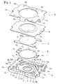
- the illustrated push-on switch S will be schematically described.
- Two dome-like movable contacts 6, 7 having different sizes and shapes are disposed in two or upper and lower stages in an accommodating portion 5 of a body 4 having a plurality of stationary contacts 1, 2, 3, and the movable contacts 6, 7 are positionally fixed in an invertible manner to the body 4, thereby configuring a two-step push-on switch (push-button switch).
- the body 4 is made of an insulating material such as a synthetic resin, and formed into a shallow box-like structure (tray-like structure) in which the stepped and recessed accommodating portion 5 is formed in the inner middle area, which has a rectangular external shape, and in which the upper face is opened.
- the accommodating portion 5 is configured by: an upper recess 5a which is formed by recessing the upper face of the body 4 by one step into an oval shape while not recessing the outer peripheral edge portion; a middle recess 5b which is formed by recessing a middle area of the oval bottom face of the upper recess 5a by one step into a circular shape; and a lower recess 5c which is formed by recessing a middle area of the circular bottom face of the middle recess 5b by one step into a circular shape.
- the recesses 5a, 5b, 5c are located concentric with the center of the body 4.
- the upper recess 5a is disposed so that both arcuate end portions are opposed to one set of short sides which are opposed to each other in the longitudinal direction of the body 4, and both linear side edges are parallel to the long sides which are opposed to each other in the lateral direction of the body 4.
- a middle bottom face (the circular bottom face of the lower recess 5c) 5d which is horizontal and circular is formed in the deepest portion of the accommodating portion 5.
- a first peripheral bottom face (the outer peripheral edge portion of the bottom face of the middle recess 5b) 5e that is horizontal and annular is formed at a position which is in the periphery of the middle bottom face 5d, and which is higher in level by one step than the middle bottom face.
- a second peripheral bottom face (both end portions of the bottom face of the upper recess 5a in the longitudinal direction of the body 4) 5f that is horizontal and arcuate is formed at two positions which sandwich the first peripheral bottom face 5e in the longitudinal direction of the body 4, and which are higher in level by one step than the first peripheral bottom face 5e.
- First leg accommodating recesses 5g which are continuous to the accommodating portion 5, and which are to accommodate leg portions 7b (described later) of the upper movable contact 7 are formed in four corners of the upper face of the body 4, respectively.
- Second leg accommodating recesses 5h which are continuous to the accommodating portion 5, and which are to accommodate leg portions 6b (described later) of the lower movable contact 6 are formed between the two first leg accommodating recesses 5g on one side in the longitudinal direction of the upper face of the body 4, and the two first leg accommodating recesses 5g on the other side in the longitudinal direction of the upper face.
- the first leg accommodating recesses 5g are formed so as to have a depth which is shallower than the depth of the upper recess 5a from the upper face of the body 4.
- Inner ends of the first leg accommodating recesses 5g are continuously connected to four corners of the upper recess 5a in positions which are higher in level by one step than the second peripheral bottom face 5f, respectively.
- third peripheral bottom faces 5i bottom faces of the first leg accommodating recesses 5g which are higher in level by one step than the second peripheral bottom face 5f are formed in four corners of the accommodating portion 5, respectively.
- the second leg accommodating recesses 5h are formed so as to have the same depth as the middle recess 5b from the upper face of the body 4, and inner ends of the second leg accommodating recesses 5h are continuously connected to the middle recess 5b on the longitudinal center line of the body 4.
- first peripheral bottom face projecting portions 5j are disposed which project flushly continuously from the first peripheral bottom face 5e on the longitudinal center line of the body 4, which cross the second peripheral bottom face 5f to interrupt it, and which form the bottom faces of the second leg accommodating recesses 5h.
- Each of the plural stationary contacts 1, 2, 3 provided on the body 4 is formed by a thin metal plate, and attached integrally to the body 4 by insert molding.
- the stationary contacts are configured respectively by: a middle stationary contact 1 which is disposed in a middle area of the middle bottom face 5d, integrally with the body 4 in a state where one end portion is exposed; first peripheral stationary contacts 2 which are disposed at symmetric positions of the outer peripheral edge portion of the first peripheral bottom face 5e on the lateral center line of the body 4, integrally with the body 4 in a state where one end portion is exposed; and second peripheral stationary contacts 3 which are disposed on the third peripheral bottom faces 5i positioned in a diagonal direction of the body 4, integrally with the body 4 in a state where one end portion is exposed.
- the lower movable contact 6 is formed by a thin metal plate spring, and configured by: an invertible contact body 6a which is circular, which has a diameter that is slightly smaller than that of the middle recess 5b, and which has a dome-like shape that is upward inflatingly curved; and right and left leg portions 6b which are elongated radially outward from the outer peripheral edge of the contact body 6a at an interval of 180 deg., and which can be accommodated in the second leg accommodating recesses 5h, respectively.
- Each of the leg portions 6b has a pressed portion 6c in which the tip end is upward bent to restrict restricting rising of the lower movable contact 6.
- the pressed portions 6c are formed so as to have a height which is substantially equal to the depth of the second leg accommodating recesses 5h from the upper face of the body 4.
- the upper movable contact 7 is formed by a thin metal plate spring, and configured by: an invertible contact body 7a which has a size that can cover the lower movable contact 6 from the upper side, which is oval unlike the lower movable contact 6, and which has a dome-like shape that is upward inflatingly curved; and four leg portions 7b which are elongated from four corners of the contact body 7a in the longitudinal direction, and which can be accommodated in the first leg accommodating recesses 5g, respectively. More specifically, the upper movable contact 7 is configured in the following manner.
- the contact body 7a has a diameter R which is larger at least than the diameter of the contact body 6a of the lower movable contact 6, and smaller than the width A1 of the longitudinal side of the body 4 (in the embodiment, the upper movable contact having a diameter R which is larger than the diameter of the contact body 6a of the lower movable contact 6, and smaller than the width A2 of the lateral side of the body 4 is shown).
- the upper movable contact is formed into an oval shape in which edge portions of a dome-like disc 70 (see the phantom lines in Fig.
- the upper movable contact is formed so as to be accommodable in the upper recess 5a of the body 4 in a direction (posture) in which, in a plan view, the linear cut edges of the contact body 7a are elongated along the one set of longitudinal sides opposed in the lateral direction of the body 4, and the arcuate uncut edges are opposed to the one set of lateral sides opposed in the longitudinal direction of the body 4.
- the leg portions 7b which can be accommodated in the first leg accommodating recesses 5g are elongated integrally and continuously from the four corners of the oval contact body 7a, in the longitudinal direction.
- the push-on switch S includes a dust-proof tape 8 and a cover 9 in addition to the body 4, the lower movable contact 6, and the upper movable contact 7.
- the dust-proof tape 8 is configured by a soft bonding tape (adhesive tape) having a bonding layer (adhesive layer) on one face, and formed into a size and a shape (in the embodiment, a rectangular shape is shown) which can cover a substantially whole area of the upper face of the body 4 and hermetically seal the accommodating portion 5.
- a soft bonding tape adheresive tape
- bonding layer adheresive layer
- the cover 9 is formed by a thin metal plate, and configured by: a rectangular top plate 9a which is to overlap with the upper face of the body 4; first positioning pieces 9b laterally disposed, which are downward elongated from middle areas of one set of longitudinal sides opposed to each other in the lateral direction of the top plate 9a, along one set of longitudinal sides opposed to each other in the lateral direction of the body 4; and second positioning pieces 9c longitudinally disposed, which are downward elongated from middle areas of one set of lateral sides opposed to each other in the longitudinal direction of the top plate 9a, along one set of lateral sides opposed to each other in the longitudinal direction of the body 4.
- a window hole 9d through which the contact body 7a of the upper movable contact 7 is to be exposed from the upper face of the top plate 9a is formed in a middle area of the top plate 9a.
- the first positioning pieces 9b are formed to have a length which is approximately equal to or smaller than the thickness of the body 4.
- the second positioning pieces 9c are formed to have a length which is larger than the thickness of the body 4 so that, after the cover 9 is attached to the body 4, tip end portions of the second positioning pieces 9c can be inwardly bent and engaged with engaging grooves 5k formed in the bottom face of the body 4.
- the contact body 6a of the lower movable contact 6 is fitted into the accommodating portion 5 while the two leg portions 6b of the lower movable contact 6 are fitted into the second leg accommodating recesses 5h from the side of the upper face of the body 4.
- the lower faces of the leg portions 6b butt against the first peripheral bottom face projecting portions 5j, an outer peripheral edge portion of the contact body 6a butts against the first peripheral bottom face 5e, and the lower movable contact 6 is incorporated into the middle recess 5b of the accommodating portion 5 of the body 4.
- the lower movable contact 6 is incorporated into the middle recess 5b of the accommodating portion 5 of the body 4, a part of the outer peripheral edge portion of the contact body 6a is contacted with the first peripheral stationary contacts 2 provided in the body 4 to be electrically connected thereto.
- the contact body 7a of the upper movable contact 7 is fitted into the accommodating portion 5 while the four leg portions 7b of the upper movable contact 7 are fitted into the first leg accommodating recesses 5g from the side of the upper face of the body 4.
- the dust-proof tape 8 is bonded to the upper face of the body 4, and then the cover 9 is placed from the side of the upper face of the body 4 to overlay the top plate 9a on the upper face of the body 4 via the dust-proof tape 8.
- the tip end portions of the second positioning pieces 9c protruding toward the bottom face of the body 4 are inward bent, and engaged with the engaging grooves 5k of the body 4.
- the first positioning pieces 9b sandwich the body 4 in the lateral direction
- the second positioning pieces 9c sandwich the body 4 in the longitudinal direction, and cooperate with the top plate 9a to sandwich the body 4 in the thickness direction, whereby the cover 9 is fixed to the body 4.
- the cover 9 Since the cover 9 is fixed to the body 4, the contact body 7a of the upper movable contact 7 which is covered by the dust-proof tape 8 is upward projected from the window hole 9d in the middle area of the top plate 9a, and the top plate 9a is attached to the upper face of the body 4 in a state where the outer peripheral edge portion of the dust-proof tape 8 is sandwiched between the outer peripheral edge portion of the top plate 9a and that of the upper face of the body 4.
- the two-step push-on switch S in which the lower movable contact 6 and the upper movable contact 7 are placed and accommodated in an invertible manner in two or upper and lower stages in the accommodating portion 5 of the body 4, in a state where the contact body 6a of the lower movable contact 6 is separated and opposed above the middle stationary contact 1 of the body 4, a part of the outer peripheral edge portion of the contact body 6a of the lower movable contact 6 is always in contact with the first peripheral stationary contacts 2 of the body 4 to be electrically connected to each other, the contact body 7a of the upper movable contact 7 is separated and opposed above the contact body 6a of the lower movable contact 6, and the lower faces of the tip end portions of the two leg portions 7b of the upper movable contact 7 are always electrically connected to the second peripheral stationary contacts 3 of the body 4.
- the outer peripheral edge portion of the oval contact body 7a is fitted into the upper recess 5a of the accommodating portion 5 disposed in the middle area of the upper face of the body 4, and the four leg portions 7b which are elongated from the four corners of the contact body 7a in the longitudinal direction are fitted into the leg accommodating recesses 5g which are formed in the four corners of the upper face of the body 4, respectively.
- the circular contact body 6a is fitted into the middle recess 5b of the accommodating portion 5 disposed in the middle area of the upper face of the body 4, and the two leg portions 6b which are elongated from the contact body 6a in the longitudinal direction of the body 4 are fitted into the second leg accommodating recesses 5h which are formed between the two first leg accommodating recesses 5g on one side in the longitudinal direction of the body 4, and the two first leg accommodating recesses 5g on the other side in the longitudinal direction.
- leg portions 6b of the lower movable contact 6 which are fitted into the second leg accommodating recesses 5h of the body 4 have the pressed portions 6c which are formed by upward bending the tip ends, the pressed portions 6c protrude toward the upper face of the upper movable contact 7 with passing between the two leg portions 7b on one side in the longitudinal direction of the upper movable contact 7, and between the two leg portions 7b on the other side in the longitudinal direction, the tip ends of the pressed portions 6 face the upper faces of the openings of the second leg accommodating recesses 5h of the body 4, and the upper faces of the openings are covered and closed by the dust-proof tape 8 and the top plate 9a of the cover 9.
- the addition of the adhesive sheet increases the number of parts.
- a step of bonding the adhesive sheet must be conducted between a step of incorporating the lower movable contact 6 and that of incorporating the upper movable contact 7, and the adhesive sheet must be accurately bonded. Therefore, the number of production steps is increased, and the production efficiency is lowered.
- the lower movable contact 6 is positionally fixed without using an adhesive sheet as described above, and hence the number of parts can be reduced so that the push-on switch S can be produced economically, easily, and efficiently.
- the push-on switch S can be reduced in size and profile.
- the lower movable contact 6 Since the pressed portions 6c of the lower movable contact 6 are projected between the leg portions 7b toward the upper face of the upper movable contact 7, the lower movable contact 6 can be positionally fixed within an area for accommodating the upper movable contact 7. Therefore, the size of the push-on switch S is not increased.
- the central area of the contact body 7a of the upper movable contact 7 is downward depressed from the side above the dust-proof tape 8 by an operating member such as a key top.
- an operating member such as a key top.
- the upper movable contact 7 is rapidly inverted to a downward inflated state, and the lower face of the central area is contacted with the upper face of the top portion of the contact body 6a of the lower movable contact 6, so that the upper movable contact 7 and the lower movable contact 6 are electrically connected to each other.
- the second peripheral stationary contacts 3 and the first peripheral stationary contacts 2 are connected to each other through the upper and lower movable contacts 7 and 6 which are in the electrically conductive state, thereby causing the first-step (upper) switch to enter the ON state with producing an operation sense.
- the lower movable contact 6 When the contact body 6a of the lower movable contact 6 cannot withstand the depressing force, the lower movable contact 6 is rapidly inverted to a downward inflated state, and the lower face of the central area makes contact with the middle stationary contact 1, and the first peripheral stationary contacts 2 and the middle stationary contact 1 are connected to each other through the lower movable contact 6, thereby causing the second-step (lower) switch to enter the ON state with producing an operation sense.
- the lower movable contact 6 has the simple circular shape in which the leg portions 6b that are irrelevant to stress, and that are used for pressing the lower movable contact are added to the circular contact body 6a that has the upward inflated dome-like shape, and that is invertible, i.e., a circular plate spring. Therefore, the characteristics of the circular plate spring are not in any way impaired, and a large life number of ON/OFF operations can be obtained.
- the contact body 7a of the upper movable contact 7 is formed into an oval shape. Even in the case where, when a depressing operation is applied so as to cause the second-step switch to be turned ON, the central area of the upper movable contact 7 is largely displaced, therefore, a stress produced in the contact body 7a is relaxed, whereby failures such as cracks or deflection (creep) can be prevented from occurring and a large life number of ON/OFF operations can be obtained.
- a body which accommodates a circular dome-like movable contact having a diameter of R must be formed into a square shape having sides of A1.
- the contact body 7a of the upper movable contact 7 is formed into an oval shape, the width of the body 4 in the lateral direction of the upper movable contact 7 can be made smaller than the width of the upper movable contact 7 in the longitudinal direction (A1 > A2), while ensuring the same operation stroke as a circular dome-like movable contact having a diameter of R. Therefore, the assembled two-step push-on switch S can be miniaturized with respect to the external dimension in the width direction.
- the push-on switch S is mounted on an apparatus such as an electronic apparatus or a communication apparatus, in a state where the external contacts 1a, 2a, 3a protruding from the body 4 are electrically connected by soldering to contacts (conductors) formed on a circuit board of the apparatus. Since miniaturization in which the dimensions, particularly the width are reduced is realized, the switch can be easily mounted even in a side face of a thin apparatus such as a portable telephone.
- the leg portions 7b of the upper movable contact 7 are elongated from the four corners of the oval contact body 7a in the longitudinal direction, and hence do not constitute an obstacle to miniaturization with respect to the width of the push-on switch S.
Landscapes
- Push-Button Switches (AREA)
- Manufacture Of Switches (AREA)
Abstract
Description
- The present invention relates to a push-on switch in which a dome-like movable contact is inverted as a result of a depressing operation to make electrical conduction, and more particularly to a two-step push-on switch into which two or upper and lower movable contacts are incorporated.
- In a push-on switch of this kind, the upper movable contact is placed in an accommodating portion of a body, and fixed by attaching a frame having a window hole at the middle to an upper face of the body via a cover sheet covering the accommodating portion and exerting also a function of dust proof, and pressing the cover sheet from the upper side. On the other hand, the lower movable contact is placed in the accommodating portion of the body and under the upper movable contact, and fixed by bonding and holding the whole outer peripheral edge portion by an annular adhesive sheet having a through hole in the middle, to the body, whereby a top of an inflated portion is exposed to be contactable to the upper movable contact in the upper side. Such a conventional push-on switch is disclosed in Japanese Patent Application Laying-Open No. 2003-7167.
- Problems which are to be solved by the invention are that, in the fixing method in which the outer peripheral edge portion of the lower movable contact is bonded and held to the body by the annular adhesive sheet, the adhesive sheet is additionally used and hence the number of parts is increased, and also that the adhesive sheet must be accurately bonded in the process of incorporating into the lower movable contact, and hence the production efficiency is lowered.
- The invention has been conducted in view of the above-mentioned circumstance. It is an object of the invention to provide a push-on switch in which a lower movable contact can be fixed to a body without using a dedicated pressing member such as an adhesive sheet, whereby cost reduction and improvement of the production efficiency can be realized.
- In order to attain the object, the invention is characterized in that, in a two-step push-on switch in which dome-like movable contacts are placed in an invertible manner in two or upper and lower stages in an accommodating portion of an insulative body having plural stationary contacts, a leg portion is elongated from an outer peripheral edge portion of the lower movable contact, and the leg portion has a pressed portion in which a tip end is upward bent to protrude toward an upper face of the upper movable contact.
- According to the invention, the pressed portion disposed at the tip end of the leg portion of the lower movable contact protrudes toward the upper face of the upper movable contact. When the position of the upper movable contact is fixed to the body, therefore, the pressed portion is pressed by fixing means for the upper movable contact to play a role of restricting rising of the lower movable contact and positionally fixing the contact. As a result, the lower movable contact can be positionally fixed without using a dedicated pressing member. Therefore, it is possible to attain the effects that the number of parts can be reduced, and that cost reduction of the push-on switch and improvement of the production efficiency can be realized.
-
- Fig. 1 is an exploded perspective view of a push-on switch of an embodiment of the invention;
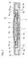
- Fig. 2 is a side section view of an assembled state of the push-on switch of the embodiment of the invention; and
- Fig. 3 is a plan view of an assembled state of the push-on switch of the embodiment of the invention in which a dust-proof tape and a cover are removed away.
-
- S
- push-on switch
- 1
- middle stationary contact
- 2
- first peripheral stationary contact
- 3
- second peripheral stationary contact
- 4
- body
- 5
- accommodating portion
- 6
- lower movable contact
- 6b
- leg portion
- 6c
- pressed portion
- 7
- upper movable contact
- 7b
- leg portion
- 8
- dust-proof tape
- 9
- cover
- Hereinafter, a push-on switch S which is an embodiment of the invention will be described with reference to the accompanying drawings.
- The illustrated push-on switch S will be schematically described. Two dome-like
movable contacts accommodating portion 5 of abody 4 having a plurality ofstationary contacts movable contacts body 4, thereby configuring a two-step push-on switch (push-button switch). - Next, the configurations of the components of the push-on switch S will be described. First, the
body 4 is made of an insulating material such as a synthetic resin, and formed into a shallow box-like structure (tray-like structure) in which the stepped and recessedaccommodating portion 5 is formed in the inner middle area, which has a rectangular external shape, and in which the upper face is opened. - The
accommodating portion 5 is configured by: anupper recess 5a which is formed by recessing the upper face of thebody 4 by one step into an oval shape while not recessing the outer peripheral edge portion; amiddle recess 5b which is formed by recessing a middle area of the oval bottom face of theupper recess 5a by one step into a circular shape; and alower recess 5c which is formed by recessing a middle area of the circular bottom face of themiddle recess 5b by one step into a circular shape. Therecesses body 4. Theupper recess 5a is disposed so that both arcuate end portions are opposed to one set of short sides which are opposed to each other in the longitudinal direction of thebody 4, and both linear side edges are parallel to the long sides which are opposed to each other in the lateral direction of thebody 4. According to the configuration, a middle bottom face (the circular bottom face of thelower recess 5c) 5d which is horizontal and circular is formed in the deepest portion of theaccommodating portion 5. A first peripheral bottom face (the outer peripheral edge portion of the bottom face of themiddle recess 5b) 5e that is horizontal and annular is formed at a position which is in the periphery of themiddle bottom face 5d, and which is higher in level by one step than the middle bottom face. A second peripheral bottom face (both end portions of the bottom face of theupper recess 5a in the longitudinal direction of the body 4) 5f that is horizontal and arcuate is formed at two positions which sandwich the firstperipheral bottom face 5e in the longitudinal direction of thebody 4, and which are higher in level by one step than the firstperipheral bottom face 5e. - First
leg accommodating recesses 5g which are continuous to theaccommodating portion 5, and which are to accommodateleg portions 7b (described later) of the uppermovable contact 7 are formed in four corners of the upper face of thebody 4, respectively. Second leg accommodatingrecesses 5h which are continuous to theaccommodating portion 5, and which are to accommodateleg portions 6b (described later) of the lowermovable contact 6 are formed between the two firstleg accommodating recesses 5g on one side in the longitudinal direction of the upper face of thebody 4, and the two firstleg accommodating recesses 5g on the other side in the longitudinal direction of the upper face. The firstleg accommodating recesses 5g are formed so as to have a depth which is shallower than the depth of theupper recess 5a from the upper face of thebody 4. Inner ends of the firstleg accommodating recesses 5g are continuously connected to four corners of theupper recess 5a in positions which are higher in level by one step than the secondperipheral bottom face 5f, respectively. According to the configuration, third peripheral bottom faces 5i (bottom faces of the firstleg accommodating recesses 5g) which are higher in level by one step than the secondperipheral bottom face 5f are formed in four corners of theaccommodating portion 5, respectively. On the other hand, the secondleg accommodating recesses 5h are formed so as to have the same depth as themiddle recess 5b from the upper face of thebody 4, and inner ends of the secondleg accommodating recesses 5h are continuously connected to themiddle recess 5b on the longitudinal center line of thebody 4. According to the configuration, first peripheral bottomface projecting portions 5j are disposed which project flushly continuously from the first peripheralbottom face 5e on the longitudinal center line of thebody 4, which cross the second peripheralbottom face 5f to interrupt it, and which form the bottom faces of the secondleg accommodating recesses 5h. - Each of the plural
stationary contacts body 4 is formed by a thin metal plate, and attached integrally to thebody 4 by insert molding. The stationary contacts are configured respectively by: a middlestationary contact 1 which is disposed in a middle area of themiddle bottom face 5d, integrally with thebody 4 in a state where one end portion is exposed; first peripheralstationary contacts 2 which are disposed at symmetric positions of the outer peripheral edge portion of the first peripheralbottom face 5e on the lateral center line of thebody 4, integrally with thebody 4 in a state where one end portion is exposed; and second peripheralstationary contacts 3 which are disposed on the third peripheral bottom faces 5i positioned in a diagonal direction of thebody 4, integrally with thebody 4 in a state where one end portion is exposed. Four end portions of the stationary contacts in total, or another end portion of the middlestationary contact 1, a common other end portion of the first peripheralstationary contacts 2, and other end portions of the second peripheralstationary contacts 3 are projected respectively from four lower end portions of one set of short side faces which are opposed to each other in the longitudinal direction of thebody 4, thereby formingexternal contacts - The lower
movable contact 6 is formed by a thin metal plate spring, and configured by: aninvertible contact body 6a which is circular, which has a diameter that is slightly smaller than that of themiddle recess 5b, and which has a dome-like shape that is upward inflatingly curved; and right andleft leg portions 6b which are elongated radially outward from the outer peripheral edge of thecontact body 6a at an interval of 180 deg., and which can be accommodated in the secondleg accommodating recesses 5h, respectively. Each of theleg portions 6b has a pressedportion 6c in which the tip end is upward bent to restrict restricting rising of the lowermovable contact 6. The pressedportions 6c are formed so as to have a height which is substantially equal to the depth of the secondleg accommodating recesses 5h from the upper face of thebody 4. - The upper
movable contact 7 is formed by a thin metal plate spring, and configured by: aninvertible contact body 7a which has a size that can cover the lowermovable contact 6 from the upper side, which is oval unlike the lowermovable contact 6, and which has a dome-like shape that is upward inflatingly curved; and fourleg portions 7b which are elongated from four corners of thecontact body 7a in the longitudinal direction, and which can be accommodated in the firstleg accommodating recesses 5g, respectively. More specifically, the uppermovable contact 7 is configured in the following manner. Thecontact body 7a has a diameter R which is larger at least than the diameter of thecontact body 6a of the lowermovable contact 6, and smaller than the width A1 of the longitudinal side of the body 4 (in the embodiment, the upper movable contact having a diameter R which is larger than the diameter of thecontact body 6a of the lowermovable contact 6, and smaller than the width A2 of the lateral side of thebody 4 is shown). The upper movable contact is formed into an oval shape in which edge portions of a dome-like disc 70 (see the phantom lines in Fig. 3) that is upward inflatingly curved are cut away by two parallel lines L1, L2 that are parallel to one set of longitudinal sides opposed to each other in the lateral direction of thebody 4, and that have a relative distance which is smaller than the relative distance between the longitudinal sides, i.e., the width A2 of the lateral side of thebody 4, and larger than the diameter of thecontact body 6a of the lowermovable contact 6. The upper movable contact is formed so as to be accommodable in theupper recess 5a of thebody 4 in a direction (posture) in which, in a plan view, the linear cut edges of thecontact body 7a are elongated along the one set of longitudinal sides opposed in the lateral direction of thebody 4, and the arcuate uncut edges are opposed to the one set of lateral sides opposed in the longitudinal direction of thebody 4. Theleg portions 7b which can be accommodated in the firstleg accommodating recesses 5g are elongated integrally and continuously from the four corners of theoval contact body 7a, in the longitudinal direction. - The push-on switch S includes a dust-
proof tape 8 and a cover 9 in addition to thebody 4, the lowermovable contact 6, and the uppermovable contact 7. - The dust-
proof tape 8 is configured by a soft bonding tape (adhesive tape) having a bonding layer (adhesive layer) on one face, and formed into a size and a shape (in the embodiment, a rectangular shape is shown) which can cover a substantially whole area of the upper face of thebody 4 and hermetically seal theaccommodating portion 5. - The cover 9 is formed by a thin metal plate, and configured by: a rectangular
top plate 9a which is to overlap with the upper face of thebody 4;first positioning pieces 9b laterally disposed, which are downward elongated from middle areas of one set of longitudinal sides opposed to each other in the lateral direction of thetop plate 9a, along one set of longitudinal sides opposed to each other in the lateral direction of thebody 4; andsecond positioning pieces 9c longitudinally disposed, which are downward elongated from middle areas of one set of lateral sides opposed to each other in the longitudinal direction of thetop plate 9a, along one set of lateral sides opposed to each other in the longitudinal direction of thebody 4. Awindow hole 9d through which thecontact body 7a of the uppermovable contact 7 is to be exposed from the upper face of thetop plate 9a is formed in a middle area of thetop plate 9a. Thefirst positioning pieces 9b are formed to have a length which is approximately equal to or smaller than the thickness of thebody 4. On the other hand, thesecond positioning pieces 9c are formed to have a length which is larger than the thickness of thebody 4 so that, after the cover 9 is attached to thebody 4, tip end portions of thesecond positioning pieces 9c can be inwardly bent and engaged withengaging grooves 5k formed in the bottom face of thebody 4. - Next, the manner of assembling the push-on switch S will be described. First, the
contact body 6a of the lowermovable contact 6 is fitted into theaccommodating portion 5 while the twoleg portions 6b of the lowermovable contact 6 are fitted into the secondleg accommodating recesses 5h from the side of the upper face of thebody 4. As a result, the lower faces of theleg portions 6b butt against the first peripheral bottomface projecting portions 5j, an outer peripheral edge portion of thecontact body 6a butts against the first peripheralbottom face 5e, and the lowermovable contact 6 is incorporated into themiddle recess 5b of theaccommodating portion 5 of thebody 4. Since the lowermovable contact 6 is incorporated into themiddle recess 5b of theaccommodating portion 5 of thebody 4, a part of the outer peripheral edge portion of thecontact body 6a is contacted with the first peripheralstationary contacts 2 provided in thebody 4 to be electrically connected thereto. Next, thecontact body 7a of the uppermovable contact 7 is fitted into theaccommodating portion 5 while the fourleg portions 7b of the uppermovable contact 7 are fitted into the first leg accommodating recesses 5g from the side of the upper face of thebody 4. As a result, the lower faces of tip end portions of theleg portions 7b butt against the third peripheral bottom faces 5i, and the uppermovable contact 7 is incorporated into theupper recess 5a in theaccommodating portion 5 of thebody 4 in a state where thecontact body 7a is supported above the opening of theupper recess 5a of theaccommodating portion 5 to protrude toward the upper face of thebody 4. Since the uppermovable contact 7 is incorporated into theupper recess 5a in theaccommodating portion 5 of thebody 4, the lower faces of the tip end portions of the twoleg portions 7b positioned in a diagonal direction of thebody 4 are contacted with the second peripheralstationary contacts 3 provided in thebody 4 to be electrically connected thereto. Next, the dust-proof tape 8 is bonded to the upper face of thebody 4, and then the cover 9 is placed from the side of the upper face of thebody 4 to overlay thetop plate 9a on the upper face of thebody 4 via the dust-proof tape 8. The tip end portions of thesecond positioning pieces 9c protruding toward the bottom face of thebody 4 are inward bent, and engaged with the engaginggrooves 5k of thebody 4. As a result, thefirst positioning pieces 9b sandwich thebody 4 in the lateral direction, and thesecond positioning pieces 9c sandwich thebody 4 in the longitudinal direction, and cooperate with thetop plate 9a to sandwich thebody 4 in the thickness direction, whereby the cover 9 is fixed to thebody 4. Since the cover 9 is fixed to thebody 4, thecontact body 7a of the uppermovable contact 7 which is covered by the dust-proof tape 8 is upward projected from thewindow hole 9d in the middle area of thetop plate 9a, and thetop plate 9a is attached to the upper face of thebody 4 in a state where the outer peripheral edge portion of the dust-proof tape 8 is sandwiched between the outer peripheral edge portion of thetop plate 9a and that of the upper face of thebody 4. - As a result, as shown in Fig. 2, it is possible to assemble the two-step push-on switch S in which the lower
movable contact 6 and the uppermovable contact 7 are placed and accommodated in an invertible manner in two or upper and lower stages in theaccommodating portion 5 of thebody 4, in a state where thecontact body 6a of the lowermovable contact 6 is separated and opposed above the middlestationary contact 1 of thebody 4, a part of the outer peripheral edge portion of thecontact body 6a of the lowermovable contact 6 is always in contact with the first peripheralstationary contacts 2 of thebody 4 to be electrically connected to each other, thecontact body 7a of the uppermovable contact 7 is separated and opposed above thecontact body 6a of the lowermovable contact 6, and the lower faces of the tip end portions of the twoleg portions 7b of the uppermovable contact 7 are always electrically connected to the second peripheralstationary contacts 3 of thebody 4. - In the thus assembled push-on switch S, the outer peripheral edge portion of the
oval contact body 7a is fitted into theupper recess 5a of theaccommodating portion 5 disposed in the middle area of the upper face of thebody 4, and the fourleg portions 7b which are elongated from the four corners of thecontact body 7a in the longitudinal direction are fitted into the legaccommodating recesses 5g which are formed in the four corners of the upper face of thebody 4, respectively. By these fittings, therefore, longitudinal and lateral movements of the uppermovable contact 7 are restricted, and the uppermovable contact 7 is positionally fixed. Furthermore, longitudinal and lateral movements of the uppermovable contact 7 are restricted also by the dust-proof tape 8 bonded to the upper face of theoval contact body 7a, and, since the upper movable contact is pressed from the upper side by the dust-proof tape 8, rising (movement of the vertical direction) is restricted, whereby the uppermovable contact 7 is positionally fixed. - In the thus assembled push-on switch S, the
circular contact body 6a is fitted into themiddle recess 5b of theaccommodating portion 5 disposed in the middle area of the upper face of thebody 4, and the twoleg portions 6b which are elongated from thecontact body 6a in the longitudinal direction of thebody 4 are fitted into the secondleg accommodating recesses 5h which are formed between the two firstleg accommodating recesses 5g on one side in the longitudinal direction of thebody 4, and the two firstleg accommodating recesses 5g on the other side in the longitudinal direction. By these fittings, therefore, longitudinal and lateral movements of the lowermovable contact 6 are restricted, and the lowermovable contact 6 is positionally fixed. Furthermore, theleg portions 6b of the lowermovable contact 6 which are fitted into the secondleg accommodating recesses 5h of thebody 4 have the pressedportions 6c which are formed by upward bending the tip ends, the pressedportions 6c protrude toward the upper face of the uppermovable contact 7 with passing between the twoleg portions 7b on one side in the longitudinal direction of the uppermovable contact 7, and between the twoleg portions 7b on the other side in the longitudinal direction, the tip ends of the pressedportions 6 face the upper faces of the openings of the secondleg accommodating recesses 5h of thebody 4, and the upper faces of the openings are covered and closed by the dust-proof tape 8 and thetop plate 9a of the cover 9. Even when the lowermovable contact 6 tends to rise, therefore, the pressedportions 6c at the tip ends of theleg portions 6b can be pressed from the upper side by the dust-proof tape 8 and thetop plate 9a of the cover 9, and hence the lowermovable contact 6 can be positionally fixed with restricting rising (movement of the vertical direction). - In the case where the fixing method in which the lower
movable contact 6 is bonded and held to thebody 4 by an annular adhesive sheet as in the conventional art is employed, the addition of the adhesive sheet increases the number of parts. During the assembling process, a step of bonding the adhesive sheet must be conducted between a step of incorporating the lowermovable contact 6 and that of incorporating the uppermovable contact 7, and the adhesive sheet must be accurately bonded. Therefore, the number of production steps is increased, and the production efficiency is lowered. In the embodiment, the lowermovable contact 6 is positionally fixed without using an adhesive sheet as described above, and hence the number of parts can be reduced so that the push-on switch S can be produced economically, easily, and efficiently. Furthermore, a space for bonding an adhesive sheet is not required to be formed in theaccommodating portion 5 of thebody 4, and also a space for accommodating a part of pressing the lower movable contact is not necessary to be ensured between the two or upper and lowermovable contacts - Since the pressed
portions 6c of the lowermovable contact 6 are projected between theleg portions 7b toward the upper face of the uppermovable contact 7, the lowermovable contact 6 can be positionally fixed within an area for accommodating the uppermovable contact 7. Therefore, the size of the push-on switch S is not increased. - Next, the operation of the push-on switch S will be described. In a state where the push-on switch S is not depressed, as shown in Fig. 2, the lower faces of the tip end portions of the two
leg portions 7b of the uppermovable contact 7 are contacted with the second peripheralstationary contacts 3 to attain electrical conduction, but thecontact body 7a is returned to an upward inflated dome-like shape, and separated from thecontact body 6a of the lowermovable contact 6. In the lowermovable contact 6, a part of the outer peripheral edge portion of thecontact body 6a is in contact with the first peripheralstationary contacts 2 to attain electrical conduction, but thecontact body 6a is returned to an upward inflated dome-like shape, and separated from the middlestationary contact 1. Therefore, both the two or upper and lower step switches are in the OFF state. - In the state of Fig. 2, then, the central area of the
contact body 7a of the uppermovable contact 7 is downward depressed from the side above the dust-proof tape 8 by an operating member such as a key top. When thecontact body 7a of the uppermovable contact 7 cannot withstand the depressing force, the uppermovable contact 7 is rapidly inverted to a downward inflated state, and the lower face of the central area is contacted with the upper face of the top portion of thecontact body 6a of the lowermovable contact 6, so that the uppermovable contact 7 and the lowermovable contact 6 are electrically connected to each other. The second peripheralstationary contacts 3 and the first peripheralstationary contacts 2 are connected to each other through the upper and lowermovable contacts - When, in the state where the first-step switch is turned ON as described above, the central area of the
contact body 7a of the uppermovable contact 7 is further downward depressed from the side above the dust-proof tape 8 by the operating member, the upper face of the top portion of thecontact body 6a of the lowermovable contact 6 is downward depressed by the lower face of the central area of thecontact body 7a of the uppermovable contact 7. When thecontact body 6a of the lowermovable contact 6 cannot withstand the depressing force, the lowermovable contact 6 is rapidly inverted to a downward inflated state, and the lower face of the central area makes contact with the middlestationary contact 1, and the first peripheralstationary contacts 2 and the middlestationary contact 1 are connected to each other through the lowermovable contact 6, thereby causing the second-step (lower) switch to enter the ON state with producing an operation sense. - When, in the state where the second-step switch is turned ON as described above, the depressing force which is applied to the
contact body 7a of the uppermovable contact 7 by the operating member is cancelled, first, thecontact body 6a of the lowermovable contact 6 is returned to its initial state or the upward inflated dome-like shape by the elasticity of itself, to attain a state where the contact body is separated from the middlestationary contact 1. Then, thecontact body 7a of the uppermovable contact 7 is returned to its initial state or the upward inflated dome-like shape by the elasticity of itself, to attain a state where thecontact body 7a is separated from thecontact body 6a of the lowermovable contact 6. As a result, both the upper- and lower-step switches enter the OFF state. - The lower
movable contact 6 has the simple circular shape in which theleg portions 6b that are irrelevant to stress, and that are used for pressing the lower movable contact are added to thecircular contact body 6a that has the upward inflated dome-like shape, and that is invertible, i.e., a circular plate spring. Therefore, the characteristics of the circular plate spring are not in any way impaired, and a large life number of ON/OFF operations can be obtained. - The
contact body 7a of the uppermovable contact 7 is formed into an oval shape. Even in the case where, when a depressing operation is applied so as to cause the second-step switch to be turned ON, the central area of the uppermovable contact 7 is largely displaced, therefore, a stress produced in thecontact body 7a is relaxed, whereby failures such as cracks or deflection (creep) can be prevented from occurring and a large life number of ON/OFF operations can be obtained. Usually, a body which accommodates a circular dome-like movable contact having a diameter of R must be formed into a square shape having sides of A1. By contrast, since thecontact body 7a of the uppermovable contact 7 is formed into an oval shape, the width of thebody 4 in the lateral direction of the uppermovable contact 7 can be made smaller than the width of the uppermovable contact 7 in the longitudinal direction (A1 > A2), while ensuring the same operation stroke as a circular dome-like movable contact having a diameter of R. Therefore, the assembled two-step push-on switch S can be miniaturized with respect to the external dimension in the width direction. The push-on switch S is mounted on an apparatus such as an electronic apparatus or a communication apparatus, in a state where theexternal contacts body 4 are electrically connected by soldering to contacts (conductors) formed on a circuit board of the apparatus. Since miniaturization in which the dimensions, particularly the width are reduced is realized, the switch can be easily mounted even in a side face of a thin apparatus such as a portable telephone. Theleg portions 7b of the uppermovable contact 7 are elongated from the four corners of theoval contact body 7a in the longitudinal direction, and hence do not constitute an obstacle to miniaturization with respect to the width of the push-on switch S.
Claims (9)
- A push-on switch in which dome-like movable contacts 6, 7 are placed in an invertible manner in two or upper and lower stages in an accommodating portion 5 of an insulative body 4 having plural stationary contacts 1, 2, 3, wherein a leg portion 6b is elongated from an outer peripheral edge portion of said lower movable contact 6, and said leg portion 6b has a pressed portion 6c in which a tip end is upward bent to protrude toward an upper face of said upper movable contact 7.
- A push-on switch according to claim 1, wherein a dust-proof tape 8 which is bonded to an upper face of said body 4 after said lower movable contact 6 and said upper movable contact 7 are incorporated in an invertible manner into two or upper and lower stages in said accommodating portion 5 of said body 4, and a cover 9 which is formed by a thin metal plate, which has a window hole 9d in a middle area, which is placed from an upper face side on said body 4 in which said dust-proof tape 8 is bonded to the upper face, and which is fixed to said body 4 in a state where a dome-like invertible contact body 7a of said upper movable contact 7 covered by said dust-proof tape 8 upward protrudes through said window hole 9d are disposed, said upper movable contact 7 is positionally fixed by pressing from an upper side said contact body 7a of said upper movable contact 7 by said dust-proof tape 8, and said lower movable contact 6 is positionally fixed by pressing from an upper side said pressed portion 6c of said lower movable contact 6 by said dust-proof tape 8.
- A push-on switch according to claim 2, wherein a plurality of leg portions 7b are elongated from an outer peripheral edge portion of said upper movable contact 7, and said pressed portion 6c of said lower movable contact 6 protrudes toward the upper face of said upper movable contact 7 with passing between said leg portions 7b of said upper movable contact 7.
- A push-on switch according to claim 3, wherein said body 4 is made of an insulating material such as a synthetic resin, and formed into a shallow box-like structure in which a stepped and recessed accommodating portion 5 is formed in a inner middle area, which has a rectangular external shape, and in which an upper face is opened, said accommodating portion 5 has: an upper recess 5a which is formed by recessing the upper face of said body 4 by one step into an oval shape while not recessing an outer peripheral edge portion; a middle recess 5b which is formed by recessing a middle area of an oval bottom face of said upper recess 5a by one step into a circular shape; and a lower recess 5c which is formed by recessing a middle area of a circular bottom face of said middle recess 5b by one step into a circular shape, said recesses 5a, 5b, 5c are located concentric with a center of said body 4, first leg accommodating recesses 5g which are continuous to said accommodating portion 5, and which are to accommodate said leg portions 7b of said upper movable contact 7 are formed in four corners of the upper face of said body 4, respectively, second leg accommodating recesses 5h which are continuous to said accommodating portion 5, and which are to accommodate said leg portions 6b of said lower movable contact 6 are formed between two first leg accommodating recesses 5g on one side in a longitudinal direction of the upper face of said body 4, and two first leg accommodating recesses 5g on another side in the longitudinal direction of the upper face, said first leg accommodating recesses 5g are formed to have a depth which is shallower than a depth of said upper recess 5a from the upper face of said body 4, inner ends of said first leg accommodating recesses 5g are continuously connected to four corners of said upper recess 5a, respectively, said second leg accommodating recesses 5h are formed to have a same depth as said middle recess 5b from the upper face of said body 4, inner ends of said second leg accommodating recesses 5h are continuously connected to said middle recess 5b on a longitudinal center line of said body 4, said plural stationary contacts are configured by: a middle stationary contact 1 which is formed by a thin metal plate, and which is disposed in a circular bottom face 5d of the lower recess 5c, integrally with said body 4 in a state where one end portion is exposed; first peripheral stationary contacts 2 which are formed by a thin metal plate, and which are disposed at symmetric positions of an annular bottom face of said middle recess 5b on a lateral center line of said body 4, integrally with said body 4 in a state where one end portion is exposed; and second peripheral stationary contacts 3 which are formed by a thin metal plate, and which are disposed on bottom faces of two first leg accommodating recesses 5g positioned in a diagonal direction of said body 4, integrally with said body 4 in a state where one end portion is exposed, and another end portion of said middle stationary contact 1, a common other end portion of said first peripheral stationary contacts 2, and other end portions of said second peripheral stationary contacts 3 are projected respectively from said body 4, thereby forming external contacts 1a, 2a, 3a.
- A push-on switch according to claim 4, wherein said lower movable contact 6 is formed by a thin metal plate, and configured by: an invertible contact body 6a which is circular, which has a diameter that is slightly smaller than that of said middle recess 5b, and which has a dome-like shape that is upward inflatingly curved; and right and left leg portions 6b which are elongated radially outward from an outer peripheral edge of said contact body 6a at an interval of 180 deg., said leg portions 6b have pressed portions 6c in which the tip end is upward bent, respectively, said pressed portions 6c are formed to have a height which is substantially equal to a depth of said second leg accommodating recesses 5h from the upper face of said body 4, said contact body 6a of said lower movable contact 6 is fitted into said accommodating portion 5 while said two leg portions 6b of said lower movable contact 6 are fitted into said second leg accommodating recesses 5h from a side of the upper face of said body 4, lower faces of said leg portions 6b butt against second leg accommodating recesses 5h, respectively, and said lower movable contact 6 is incorporated into said middle recess 5b of said accommodating portion 5 of said body 4 in a state where an outer peripheral edge portion of said contact body 6a butts against a bottom face of said middle recess 5b to contact said outer peripheral edge portion of said contact body 6a with said first stationary contacts 2 to be electrically connected thereto.
- A push-on switch according to claim 5, wherein said upper movable contact 7 is formed by a thin metal plate, and configured by: an oval invertible contact body 7a which has a size that can cover said lower movable contact 6 from an upper side, and which has a dome-like shape that is upward inflatingly curved; and four leg portions 7b which are elongated from four corners of said contact body 7a in a longitudinal direction, respectively, said contact body 7a of said upper movable contact 7 is fitted into said accommodating portion 5 while, after said lower movable contact 6 is incorporated into said middle recess 5b in said accommodating portion 5 of said body 4, four leg portions 7b of said upper movable contact 7 are fitted into said first leg accommodating recesses 5g from the side of the upper face of said body 4, and said upper movable contact 7 is incorporated into said upper recess 5a in said accommodating portion 5 of said body 4, in a state where lower faces of tip end portions of said leg portions 7b butt against bottom faces 5i of said first leg accommodating recesses 5g, whereby the upper movable contact 7 is supported above said opening of said upper recess 5a of said accommodating portion 5 to protrude toward the upper face of said body 4, and the lower faces of said tip end portions of said two leg portions 7b positioned in a diagonal direction of said body 4 are contacted with said second peripheral stationary contacts 3 to be electrically connected thereto.
- A push-on switch according to claim 6, wherein said dust-proof tape 8 is configured by a soft bonding tape having a bonding layer on one face, and formed into a size and a shape which can cover a substantially whole area of the upper face of said body 4 and hermetically seal said accommodating portion 5, and bonded to the upper face of said body 4 after said lower movable contact 6 and said upper movable contact 7 are incorporated into an invertible manner in two or upper and lower stages into said accommodating portion 5 of said body 4.
- A push-on switch according to claim 7, wherein said cover 9 is formed by a thin metal plate, and configured by: a rectangular top plate 9a which is to overlap with the upper face of said body 4; first positioning pieces 9b which are downward elongated from middle areas of longitudinal sides of said top plate 9a; second positioning pieces 9c which are elongated from middle areas of lateral sides of said top plate 9a; and a window hole 9d which is formed in a middle area of said top plate 9a, said cover 9 is put on the upper face of said body 4 after said dust-proof tape 8 is bonded to the upper face of said body 4, said top plate 9a overlays the upper face of said body 4 via said dust-proof tape 8, said first positioning pieces 9b sandwich said body 4 in the lateral direction, said second positioning pieces 9c sandwich said body 4 in the longitudinal direction, tip end portions of said second positioning pieces 9c are inwardly bent and engaged with the bottom face of said body 4, said contact body 7a of said upper movable contact 7 which is covered by said dust-proof tape 8 is upward projected from said window hole 9d in the middle area of said top plate 9a, and said cover 9 is fixed to said body 4 in a state where an outer peripheral edge portion of said dust-proof tape 8 is sandwiched between an outer peripheral edge portion of said top plate 9a and an outer peripheral edge portion of the upper face of said body 4.
- A push-on switch according to claim 8, wherein said contact body 7a of said upper movable contact 7 which is upward projected from said window hole 9d of said top plate 9a of said cover 9 is downward depressed from a side above said dust-proof tape 8, whereby said contact body 7a of said upper movable contact 7 is inverted to a downward inflated state to contact with said contact body 6a of said lower movable contact 6, said upper movable contact 7 and said lower movable contact 6 are electrically connected to each other, said second peripheral stationary contacts 3 and said first peripheral stationary contacts 2 are connected to each other through said upper movable contact 7 and said lower movable contact 6 which are in the electrically conductive state, and a first-step switch enters an ON state, said contact body 7a of said upper movable contact 7 is further downward depressed from the side above said dust-proof tape 8 in a state where the first-step switch is turned ON, and said contact body 6a of said lower movable contact 6 is downward depressed by said contact body 7a of said upper movable contact 7, whereby said contact body 6a of said lower movable contact 6 is inverted to a downward inflated state to contact with said middle stationary contact 1, said first peripheral stationary contacts 2 and said middle stationary contact 1 are connected to each other through said lower movable contact 6, and a second-step switch enters an ON state.
Applications Claiming Priority (1)
| Application Number | Priority Date | Filing Date | Title |
|---|---|---|---|
| JP2004353539A JP4371987B2 (en) | 2004-12-07 | 2004-12-07 | Push-on switch |
Publications (3)
| Publication Number | Publication Date |
|---|---|
| EP1670012A2 true EP1670012A2 (en) | 2006-06-14 |
| EP1670012A3 EP1670012A3 (en) | 2007-07-04 |
| EP1670012B1 EP1670012B1 (en) | 2014-03-19 |
Family
ID=35677411
Family Applications (1)
| Application Number | Title | Priority Date | Filing Date |
|---|---|---|---|
| EP05111372.8A Expired - Lifetime EP1670012B1 (en) | 2004-12-07 | 2005-11-28 | Push-on switch |
Country Status (6)
| Country | Link |
|---|---|
| US (1) | US7250581B2 (en) |
| EP (1) | EP1670012B1 (en) |
| JP (1) | JP4371987B2 (en) |
| KR (1) | KR100664365B1 (en) |
| CN (1) | CN100557745C (en) |
| TW (1) | TWI284337B (en) |
Cited By (4)
| Publication number | Priority date | Publication date | Assignee | Title |
|---|---|---|---|---|
| US7250581B2 (en) * | 2004-12-07 | 2007-07-31 | Hosiden Corporation | Push-on switch |
| FR2913809A1 (en) * | 2007-03-14 | 2008-09-19 | Nicomatic Sa Sa | PUSH BUTTON TYPE SWITCH, AND PRINTED CIRCUIT INCLUDING THE SAME |
| EP2645391A1 (en) * | 2012-03-27 | 2013-10-02 | RAFI GmbH & Co. KG | Switch device and switch contact |
| EP3116011A1 (en) * | 2015-07-08 | 2017-01-11 | Scanreco AB | Multiple state switch assembly |
Families Citing this family (31)
| Publication number | Priority date | Publication date | Assignee | Title |
|---|---|---|---|---|
| DE102004040395A1 (en) * | 2003-08-23 | 2005-03-24 | Marquardt Gmbh | Electrical switch used as short-stroke key for keyboard or operating field has housing base provided with recess on its underside receiving projections of housing cover side edge |
| USD533144S1 (en) * | 2005-02-18 | 2006-12-05 | Hosiden Corporation | Push-button switch |
| USD537797S1 (en) * | 2005-08-30 | 2007-03-06 | Matsushita Electric Industrial Co., Ltd. | Switch |
| US7250579B2 (en) * | 2005-09-21 | 2007-07-31 | Micro Pneumatic Logic, Inc. | Large actuation area switching device |
| US20070247777A1 (en) * | 2006-04-24 | 2007-10-25 | Inventec Corporation | Protective structure for electrostatic discharge |
| JP4802930B2 (en) * | 2006-08-10 | 2011-10-26 | パナソニック株式会社 | Push switch |
| TWD121829S1 (en) * | 2006-10-11 | 2008-03-11 | 星電股份有限公司 | Switch |
| US7569783B2 (en) * | 2007-02-21 | 2009-08-04 | Burger & Brown Engineering, Inc. | Low-profile switch with flat spring actuating mechanism |
| US20080237008A1 (en) * | 2007-03-26 | 2008-10-02 | Ming-Han Lin | Dust-proof switch |
| USD589904S1 (en) | 2007-05-21 | 2009-04-07 | Smk Corporation | Switch |
| KR100925067B1 (en) | 2007-09-04 | 2009-11-04 | 이수호 | 2 position switch |
| KR100950799B1 (en) * | 2007-10-22 | 2010-04-02 | 주식회사 두성테크 | Switch Dome |
| US7652216B2 (en) * | 2007-12-18 | 2010-01-26 | Streamlight, Inc. | Electrical switch, as for controlling a flashlight |
| US8111522B2 (en) * | 2008-04-29 | 2012-02-07 | Apple Inc. | Switch structures for use on printed circuit boards |
| JP5083057B2 (en) * | 2008-06-13 | 2012-11-28 | パナソニック株式会社 | Push switch |
| USD598870S1 (en) * | 2008-09-02 | 2009-08-25 | Hosiden Corporation | Push-button switch |
| CA129600S (en) * | 2008-09-09 | 2009-10-05 | Hosiden Corp | Push switch |
| TWD133892S1 (en) * | 2008-11-11 | 2010-03-21 | 星電股份有限公司 | Switch |
| USD627745S1 (en) | 2009-07-30 | 2010-11-23 | Hosiden Corporation | Switch |
| USD639749S1 (en) | 2009-07-30 | 2011-06-14 | Hosiden Corporation | Switch |
| JP5554983B2 (en) * | 2009-12-22 | 2014-07-23 | キヤノン株式会社 | Electronics |
| USD702577S1 (en) * | 2011-04-13 | 2014-04-15 | Mitsubishi Electric Corporation | Operation button for elevator |
| TWD156201S (en) * | 2011-11-14 | 2013-10-01 | Smk股份有限公司 | Switch |
| JP5376026B2 (en) * | 2012-08-30 | 2013-12-25 | パナソニック株式会社 | Push switch |
| USD714230S1 (en) * | 2013-04-30 | 2014-09-30 | Hon Hai Precision Industry Co., Ltd. | Switch |
| EP3297012A4 (en) * | 2015-05-09 | 2018-06-06 | Alps Electric Co., Ltd. | Push switch |
| US10083807B2 (en) | 2016-05-24 | 2018-09-25 | Apple Inc. | Metal switch for input device |
| JP7122502B2 (en) * | 2017-02-28 | 2022-08-22 | パナソニックIpマネジメント株式会社 | push switch |
| WO2018159050A1 (en) * | 2017-02-28 | 2018-09-07 | パナソニックIpマネジメント株式会社 | Push switch |
| CN110268494B (en) | 2017-02-28 | 2021-10-29 | 松下知识产权经营株式会社 | push switch |
| JP2022181546A (en) * | 2021-05-26 | 2022-12-08 | シチズン電子株式会社 | switch |
Family Cites Families (17)
| Publication number | Priority date | Publication date | Assignee | Title |
|---|---|---|---|---|
| US4359614A (en) * | 1981-09-24 | 1982-11-16 | Illinois Tool Works Inc. | Miniature two-level pushbutton switch |
| US5343008A (en) * | 1992-02-19 | 1994-08-30 | Ipcinski Ralph G | Sealed switch |
| US5898147A (en) * | 1997-10-29 | 1999-04-27 | C & K Components, Inc. | Dual tact switch assembly |
| JP2000322974A (en) * | 1999-05-10 | 2000-11-24 | Alps Electric Co Ltd | Press button switch |
| JP2003007168A (en) * | 2001-06-21 | 2003-01-10 | Alps Electric Co Ltd | Push-button switch |
| JP3916892B2 (en) | 2001-06-21 | 2007-05-23 | アルプス電気株式会社 | Push button switch |
| US6771253B2 (en) * | 2001-11-27 | 2004-08-03 | Shin Jiuh Corp. | Switch having light generator |
| JP4359812B2 (en) * | 2002-07-08 | 2009-11-11 | 日本電気株式会社 | Switch-integrated casing and electronic device having the same |
| JP2004111148A (en) * | 2002-09-17 | 2004-04-08 | Alps Electric Co Ltd | Push button switch and mounting structure therefor |
| JP2004193047A (en) * | 2002-12-13 | 2004-07-08 | Matsushita Electric Ind Co Ltd | Movable contact body with pressing projection |
| US7021790B2 (en) * | 2003-07-22 | 2006-04-04 | Armament Systems & Procedures, Inc. | Miniature LED flashlight with snap-on carrier |
| CN2643462Y (en) * | 2003-09-16 | 2004-09-22 | 林锡埼 | Two-stage touch switch |
| JP2005340154A (en) * | 2004-03-12 | 2005-12-08 | Fuji Denshi Kogyo Kk | 2-stage operation switch |
| JP4445837B2 (en) * | 2004-04-21 | 2010-04-07 | ホシデン株式会社 | Push-on switch |
| US7070349B2 (en) * | 2004-06-18 | 2006-07-04 | Motorola, Inc. | Thin keyboard and components for electronics devices and methods |
| JP4371987B2 (en) * | 2004-12-07 | 2009-11-25 | ホシデン株式会社 | Push-on switch |
| DE202005001495U1 (en) * | 2005-01-31 | 2005-06-09 | Trw Automotive Electronics & Components Gmbh & Co. Kg | 2-pole changeover switch |
-
2004
- 2004-12-07 JP JP2004353539A patent/JP4371987B2/en not_active Expired - Fee Related
-
2005
- 2005-10-14 TW TW094135979A patent/TWI284337B/en not_active IP Right Cessation
- 2005-10-27 CN CNB200510116030XA patent/CN100557745C/en not_active Expired - Lifetime
- 2005-11-28 EP EP05111372.8A patent/EP1670012B1/en not_active Expired - Lifetime
- 2005-11-29 US US11/288,108 patent/US7250581B2/en not_active Expired - Lifetime
- 2005-12-05 KR KR1020050117439A patent/KR100664365B1/en not_active Expired - Lifetime
Cited By (6)
| Publication number | Priority date | Publication date | Assignee | Title |
|---|---|---|---|---|
| US7250581B2 (en) * | 2004-12-07 | 2007-07-31 | Hosiden Corporation | Push-on switch |
| FR2913809A1 (en) * | 2007-03-14 | 2008-09-19 | Nicomatic Sa Sa | PUSH BUTTON TYPE SWITCH, AND PRINTED CIRCUIT INCLUDING THE SAME |
| WO2008129193A3 (en) * | 2007-03-14 | 2008-12-18 | Nicomatic Sa | Pusher-type vault switch and printed circuit including same |
| US8278580B2 (en) | 2007-03-14 | 2012-10-02 | Nicomatic Sa | Dome switch utilizing two domes |
| EP2645391A1 (en) * | 2012-03-27 | 2013-10-02 | RAFI GmbH & Co. KG | Switch device and switch contact |
| EP3116011A1 (en) * | 2015-07-08 | 2017-01-11 | Scanreco AB | Multiple state switch assembly |
Also Published As
| Publication number | Publication date |
|---|---|
| TWI284337B (en) | 2007-07-21 |
| JP4371987B2 (en) | 2009-11-25 |
| EP1670012A3 (en) | 2007-07-04 |
| EP1670012B1 (en) | 2014-03-19 |
| KR20060063721A (en) | 2006-06-12 |
| KR100664365B1 (en) | 2007-01-02 |
| CN100557745C (en) | 2009-11-04 |
| US7250581B2 (en) | 2007-07-31 |
| JP2006164711A (en) | 2006-06-22 |
| US20060131153A1 (en) | 2006-06-22 |
| TW200629317A (en) | 2006-08-16 |
| CN1787142A (en) | 2006-06-14 |
Similar Documents
| Publication | Publication Date | Title |
|---|---|---|
| EP1670012B1 (en) | Push-on switch | |
| EP1589552B1 (en) | Push-on Switch | |
| EP1884971B1 (en) | Lateral pushing type push switch | |
| EP2015328B1 (en) | Push-button switch | |
| EP1202311B1 (en) | Slide switch | |
| US6974919B2 (en) | Switch device and horn switch having the structure of the switch device | |
| JP2003297175A (en) | Push-on switch | |
| US6423911B2 (en) | Multi-directional operating switch capable of being operated in both depressing direction and tilting direction | |
| JP3936852B2 (en) | Slide operation switch | |
| US11462370B2 (en) | Push switch | |
| JP2005129301A (en) | Push-button switch | |
| KR200263754Y1 (en) | Tact switch form pcb printed circuit board | |
| JP5467204B2 (en) | Projection forming member and method of manufacturing projection formation member | |
| JPH051861Y2 (en) | ||
| JP2010020911A (en) | Installation structure of push-button switch | |
| JPH069396Y2 (en) | Push-button switch | |
| JP4044395B2 (en) | Push button switch | |
| KR200241402Y1 (en) | Tact switch form pcb printed circuit board | |
| JP2518255Y2 (en) | Push button switch | |
| JP2005190812A (en) | Two-stage push switch | |
| JP3023825B2 (en) | Slide switch | |
| JP2882558B2 (en) | Illuminated pushbutton switch | |
| JPH10112240A (en) | Two-stage push switch and movable plate with legs | |
| JPH05290671A (en) | Push-button switch | |
| JP2005056724A (en) | Push-button switch |
Legal Events
| Date | Code | Title | Description |
|---|---|---|---|
| PUAI | Public reference made under article 153(3) epc to a published international application that has entered the european phase |
Free format text: ORIGINAL CODE: 0009012 |
|
| AK | Designated contracting states |
Kind code of ref document: A2 Designated state(s): AT BE BG CH CY CZ DE DK EE ES FI FR GB GR HU IE IS IT LI LT LU LV MC NL PL PT RO SE SI SK TR |
|
| AX | Request for extension of the european patent |
Extension state: AL BA HR MK YU |
|
| PUAL | Search report despatched |
Free format text: ORIGINAL CODE: 0009013 |
|
| AK | Designated contracting states |
Kind code of ref document: A3 Designated state(s): AT BE BG CH CY CZ DE DK EE ES FI FR GB GR HU IE IS IT LI LT LU LV MC NL PL PT RO SE SI SK TR |
|
| AX | Request for extension of the european patent |
Extension state: AL BA HR MK YU |
|
| RIC1 | Information provided on ipc code assigned before grant |
Ipc: H01H 13/48 20060101ALI20070525BHEP Ipc: H01H 13/64 20060101ALI20070525BHEP Ipc: H01H 13/807 20060101AFI20060508BHEP |
|
| 17P | Request for examination filed |
Effective date: 20080102 |
|
| AKX | Designation fees paid |
Designated state(s): AT BE BG CH CY CZ DE DK EE ES FI FR GB GR HU IE IS IT LI LT LU LV MC NL PL PT RO SE SI SK TR |
|
| 17Q | First examination report despatched |
Effective date: 20100805 |
|
| GRAP | Despatch of communication of intention to grant a patent |
Free format text: ORIGINAL CODE: EPIDOSNIGR1 |
|
| INTG | Intention to grant announced |
Effective date: 20131008 |
|
| RAP1 | Party data changed (applicant data changed or rights of an application transferred) |
Owner name: HOSIDEN CORPORATION |
|
| GRAS | Grant fee paid |
Free format text: ORIGINAL CODE: EPIDOSNIGR3 |
|
| GRAA | (expected) grant |
Free format text: ORIGINAL CODE: 0009210 |
|
| AK | Designated contracting states |
Kind code of ref document: B1 Designated state(s): AT BE BG CH CY CZ DE DK EE ES FI FR GB GR HU IE IS IT LI LT LU LV MC NL PL PT RO SE SI SK TR |
|
| REG | Reference to a national code |
Ref country code: GB Ref legal event code: FG4D |
|
| REG | Reference to a national code |
Ref country code: CH Ref legal event code: EP |
|
| REG | Reference to a national code |
Ref country code: IE Ref legal event code: FG4D |
|
| REG | Reference to a national code |
Ref country code: AT Ref legal event code: REF Ref document number: 658136 Country of ref document: AT Kind code of ref document: T Effective date: 20140415 |
|
| REG | Reference to a national code |
Ref country code: DE Ref legal event code: R096 Ref document number: 602005042999 Country of ref document: DE Effective date: 20140430 |
|
| PG25 | Lapsed in a contracting state [announced via postgrant information from national office to epo] |
Ref country code: LT Free format text: LAPSE BECAUSE OF FAILURE TO SUBMIT A TRANSLATION OF THE DESCRIPTION OR TO PAY THE FEE WITHIN THE PRESCRIBED TIME-LIMIT Effective date: 20140319 |
|
| REG | Reference to a national code |
Ref country code: NL Ref legal event code: VDEP Effective date: 20140319 |
|
| REG | Reference to a national code |
Ref country code: AT Ref legal event code: MK05 Ref document number: 658136 Country of ref document: AT Kind code of ref document: T Effective date: 20140319 |
|
| REG | Reference to a national code |
Ref country code: LT Ref legal event code: MG4D |
|
| PG25 | Lapsed in a contracting state [announced via postgrant information from national office to epo] |
Ref country code: SE Free format text: LAPSE BECAUSE OF FAILURE TO SUBMIT A TRANSLATION OF THE DESCRIPTION OR TO PAY THE FEE WITHIN THE PRESCRIBED TIME-LIMIT Effective date: 20140319 Ref country code: CY Free format text: LAPSE BECAUSE OF FAILURE TO SUBMIT A TRANSLATION OF THE DESCRIPTION OR TO PAY THE FEE WITHIN THE PRESCRIBED TIME-LIMIT Effective date: 20140319 |
|
| PG25 | Lapsed in a contracting state [announced via postgrant information from national office to epo] |
Ref country code: LV Free format text: LAPSE BECAUSE OF FAILURE TO SUBMIT A TRANSLATION OF THE DESCRIPTION OR TO PAY THE FEE WITHIN THE PRESCRIBED TIME-LIMIT Effective date: 20140319 |
|
| PG25 | Lapsed in a contracting state [announced via postgrant information from national office to epo] |
Ref country code: IS Free format text: LAPSE BECAUSE OF FAILURE TO SUBMIT A TRANSLATION OF THE DESCRIPTION OR TO PAY THE FEE WITHIN THE PRESCRIBED TIME-LIMIT Effective date: 20140719 Ref country code: BG Free format text: LAPSE BECAUSE OF FAILURE TO SUBMIT A TRANSLATION OF THE DESCRIPTION OR TO PAY THE FEE WITHIN THE PRESCRIBED TIME-LIMIT Effective date: 20140619 Ref country code: NL Free format text: LAPSE BECAUSE OF FAILURE TO SUBMIT A TRANSLATION OF THE DESCRIPTION OR TO PAY THE FEE WITHIN THE PRESCRIBED TIME-LIMIT Effective date: 20140319 Ref country code: RO Free format text: LAPSE BECAUSE OF FAILURE TO SUBMIT A TRANSLATION OF THE DESCRIPTION OR TO PAY THE FEE WITHIN THE PRESCRIBED TIME-LIMIT Effective date: 20140319 Ref country code: CZ Free format text: LAPSE BECAUSE OF FAILURE TO SUBMIT A TRANSLATION OF THE DESCRIPTION OR TO PAY THE FEE WITHIN THE PRESCRIBED TIME-LIMIT Effective date: 20140319 Ref country code: EE Free format text: LAPSE BECAUSE OF FAILURE TO SUBMIT A TRANSLATION OF THE DESCRIPTION OR TO PAY THE FEE WITHIN THE PRESCRIBED TIME-LIMIT Effective date: 20140319 Ref country code: BE Free format text: LAPSE BECAUSE OF FAILURE TO SUBMIT A TRANSLATION OF THE DESCRIPTION OR TO PAY THE FEE WITHIN THE PRESCRIBED TIME-LIMIT Effective date: 20140319 |
|
| PG25 | Lapsed in a contracting state [announced via postgrant information from national office to epo] |
Ref country code: PL Free format text: LAPSE BECAUSE OF FAILURE TO SUBMIT A TRANSLATION OF THE DESCRIPTION OR TO PAY THE FEE WITHIN THE PRESCRIBED TIME-LIMIT Effective date: 20140319 Ref country code: SK Free format text: LAPSE BECAUSE OF FAILURE TO SUBMIT A TRANSLATION OF THE DESCRIPTION OR TO PAY THE FEE WITHIN THE PRESCRIBED TIME-LIMIT Effective date: 20140319 Ref country code: AT Free format text: LAPSE BECAUSE OF FAILURE TO SUBMIT A TRANSLATION OF THE DESCRIPTION OR TO PAY THE FEE WITHIN THE PRESCRIBED TIME-LIMIT Effective date: 20140319 Ref country code: ES Free format text: LAPSE BECAUSE OF FAILURE TO SUBMIT A TRANSLATION OF THE DESCRIPTION OR TO PAY THE FEE WITHIN THE PRESCRIBED TIME-LIMIT Effective date: 20140319 |
|
| REG | Reference to a national code |
Ref country code: DE Ref legal event code: R097 Ref document number: 602005042999 Country of ref document: DE |
|
| PLBE | No opposition filed within time limit |
Free format text: ORIGINAL CODE: 0009261 |
|
| STAA | Information on the status of an ep patent application or granted ep patent |
Free format text: STATUS: NO OPPOSITION FILED WITHIN TIME LIMIT |
|
| PG25 | Lapsed in a contracting state [announced via postgrant information from national office to epo] |
Ref country code: DK Free format text: LAPSE BECAUSE OF FAILURE TO SUBMIT A TRANSLATION OF THE DESCRIPTION OR TO PAY THE FEE WITHIN THE PRESCRIBED TIME-LIMIT Effective date: 20140319 |
|
| 26N | No opposition filed |
Effective date: 20141222 |
|
| PG25 | Lapsed in a contracting state [announced via postgrant information from national office to epo] |
Ref country code: IT Free format text: LAPSE BECAUSE OF FAILURE TO SUBMIT A TRANSLATION OF THE DESCRIPTION OR TO PAY THE FEE WITHIN THE PRESCRIBED TIME-LIMIT Effective date: 20140319 |
|
| REG | Reference to a national code |
Ref country code: DE Ref legal event code: R097 Ref document number: 602005042999 Country of ref document: DE Effective date: 20141222 |
|
| PG25 | Lapsed in a contracting state [announced via postgrant information from national office to epo] |
Ref country code: MC Free format text: LAPSE BECAUSE OF FAILURE TO SUBMIT A TRANSLATION OF THE DESCRIPTION OR TO PAY THE FEE WITHIN THE PRESCRIBED TIME-LIMIT Effective date: 20140319 Ref country code: LU Free format text: LAPSE BECAUSE OF FAILURE TO SUBMIT A TRANSLATION OF THE DESCRIPTION OR TO PAY THE FEE WITHIN THE PRESCRIBED TIME-LIMIT Effective date: 20141128 |
|
| REG | Reference to a national code |
Ref country code: CH Ref legal event code: PL |
|
| PG25 | Lapsed in a contracting state [announced via postgrant information from national office to epo] |
Ref country code: CH Free format text: LAPSE BECAUSE OF NON-PAYMENT OF DUE FEES Effective date: 20141130 Ref country code: LI Free format text: LAPSE BECAUSE OF NON-PAYMENT OF DUE FEES Effective date: 20141130 Ref country code: SI Free format text: LAPSE BECAUSE OF FAILURE TO SUBMIT A TRANSLATION OF THE DESCRIPTION OR TO PAY THE FEE WITHIN THE PRESCRIBED TIME-LIMIT Effective date: 20140319 |
|
| REG | Reference to a national code |
Ref country code: IE Ref legal event code: MM4A |
|
| PG25 | Lapsed in a contracting state [announced via postgrant information from national office to epo] |
Ref country code: IE Free format text: LAPSE BECAUSE OF NON-PAYMENT OF DUE FEES Effective date: 20141128 |
|
| REG | Reference to a national code |
Ref country code: FR Ref legal event code: PLFP Year of fee payment: 11 |
|
| PG25 | Lapsed in a contracting state [announced via postgrant information from national office to epo] |
Ref country code: PT Free format text: LAPSE BECAUSE OF FAILURE TO SUBMIT A TRANSLATION OF THE DESCRIPTION OR TO PAY THE FEE WITHIN THE PRESCRIBED TIME-LIMIT Effective date: 20140319 Ref country code: GR Free format text: LAPSE BECAUSE OF FAILURE TO SUBMIT A TRANSLATION OF THE DESCRIPTION OR TO PAY THE FEE WITHIN THE PRESCRIBED TIME-LIMIT Effective date: 20140620 |
|
| PG25 | Lapsed in a contracting state [announced via postgrant information from national office to epo] |
Ref country code: HU Free format text: LAPSE BECAUSE OF FAILURE TO SUBMIT A TRANSLATION OF THE DESCRIPTION OR TO PAY THE FEE WITHIN THE PRESCRIBED TIME-LIMIT; INVALID AB INITIO Effective date: 20051128 Ref country code: TR Free format text: LAPSE BECAUSE OF FAILURE TO SUBMIT A TRANSLATION OF THE DESCRIPTION OR TO PAY THE FEE WITHIN THE PRESCRIBED TIME-LIMIT Effective date: 20140319 |
|
| REG | Reference to a national code |
Ref country code: FR Ref legal event code: PLFP Year of fee payment: 12 |
|
| REG | Reference to a national code |
Ref country code: FR Ref legal event code: PLFP Year of fee payment: 13 |
|
| PGFP | Annual fee paid to national office [announced via postgrant information from national office to epo] |
Ref country code: GB Payment date: 20231123 Year of fee payment: 19 |
|
| PGFP | Annual fee paid to national office [announced via postgrant information from national office to epo] |
Ref country code: FR Payment date: 20231120 Year of fee payment: 19 Ref country code: FI Payment date: 20231121 Year of fee payment: 19 Ref country code: DE Payment date: 20231121 Year of fee payment: 19 |
|
| REG | Reference to a national code |
Ref country code: DE Ref legal event code: R119 Ref document number: 602005042999 Country of ref document: DE |
|
| PG25 | Lapsed in a contracting state [announced via postgrant information from national office to epo] |
Ref country code: FI Free format text: LAPSE BECAUSE OF NON-PAYMENT OF DUE FEES Effective date: 20241128 |
|
| GBPC | Gb: european patent ceased through non-payment of renewal fee |
Effective date: 20241128 |
|
| PG25 | Lapsed in a contracting state [announced via postgrant information from national office to epo] |
Ref country code: DE Free format text: LAPSE BECAUSE OF NON-PAYMENT OF DUE FEES Effective date: 20250603 |
|
| PG25 | Lapsed in a contracting state [announced via postgrant information from national office to epo] |
Ref country code: GB Free format text: LAPSE BECAUSE OF NON-PAYMENT OF DUE FEES Effective date: 20241128 |
|
| PG25 | Lapsed in a contracting state [announced via postgrant information from national office to epo] |
Ref country code: FR Free format text: LAPSE BECAUSE OF NON-PAYMENT OF DUE FEES Effective date: 20241130 |