EP1669821A1 - Driving method of a vibrating device for a portable object, with a coil and a moving mass - Google Patents
Driving method of a vibrating device for a portable object, with a coil and a moving mass Download PDFInfo
- Publication number
- EP1669821A1 EP1669821A1 EP05111845A EP05111845A EP1669821A1 EP 1669821 A1 EP1669821 A1 EP 1669821A1 EP 05111845 A EP05111845 A EP 05111845A EP 05111845 A EP05111845 A EP 05111845A EP 1669821 A1 EP1669821 A1 EP 1669821A1
- Authority
- EP
- European Patent Office
- Prior art keywords
- coil
- pulses
- voltage
- moving mass
- vibrating device
- Prior art date
- Legal status (The legal status is an assumption and is not a legal conclusion. Google has not performed a legal analysis and makes no representation as to the accuracy of the status listed.)
- Granted
Links
Images


Classifications
-
- G—PHYSICS
- G04—HOROLOGY
- G04G—ELECTRONIC TIME-PIECES
- G04G21/00—Input or output devices integrated in time-pieces
-
- G—PHYSICS
- G08—SIGNALLING
- G08B—SIGNALLING OR CALLING SYSTEMS; ORDER TELEGRAPHS; ALARM SYSTEMS
- G08B6/00—Tactile signalling systems, e.g. personal calling systems
Definitions
- the present invention relates to a method of driving a vibrating device for a portable object.
- the vibrating device comprises a movable mass and an annular-shaped coil electromagnetically coupled with the moving mass to oscillate it.
- the vibrating device can serve in particular as a silent alarm or to signal a telephone call.
- vibrating devices capable of performing the function including silent alarm to equip small portable objects, such as mobile phones, traditional organizers, paging devices or wristwatches. At least one coil of these vibrating devices can be electrically activated to actuate a mass to create a low frequency vibration that can be felt by the wearer of such an object.
- the frequency of the electrical signals applied to the coil is adjusted to correspond to the natural frequency of mechanical oscillation of the moving mass of the vibrating device. In this way, a maximum vibration amplitude can be obtained for a minimum amount of electrical energy supplied.
- the vibration of the device can be controlled according to a specific programming of the portable object so as to warn the wearer of a specific event, such as a wake-up time, a phone call or other.
- WO 02/46847 describes a method of driving such a vibrating device.
- the vibrating device comprises a moving mass having a permanent magnet and a coil electromagnetically coupled to the moving mass to oscillate it.
- a driving circuit must provide the coil of the vibrating device with rectangular pulses of maintenance voltage alternating polarity and duration determined after a starting phase of the vibrating device.
- the amplitude of the maintenance pulses corresponds approximately to the battery voltage electrically supplying the drive circuit.
- the coil is disconnected, i.e. it is placed in a high impedance state. In this state, the coil provides an induced voltage due to the movement of the permanent magnet of the oscillating mass.
- a measurement of the resonance frequency is made at each pass by zero of the induced voltage in the drive circuit to adjust the period of the rectangular maintenance pulses supplied to the coil.
- a disadvantage of such a drive method is that at each disconnection of the coil placed in the high impedance state, overvoltages, whose time constant is dependent on the characteristics of the coil, can be observed. These overvoltages can damage the drive or power electronics. Moreover with these overvoltages, it must be observed, before the measurement of the frequency, a long time of deficiency, which can be of the order of a few hundred microseconds so as not to detect unwanted zero crossings. This waiting time, which must be observed, limits the oscillation frequency to a low value. It is therefore necessary to filter these overvoltages by adequate means either at the input of an amplifier comparator of the circuit, or at the output of the comparator. This involves providing the drive circuit of additional electronic components to the proper maintenance function oscillations of the moving mass, which complicates the realization of said circuit.
- the maintenance voltage pulses are composed of a fundamental frequency f 0 and harmonic frequencies f 1 , f 2 , which create power losses and losses. parasitic forces, and which oppose the active driving force of the oscillating mass. As a result, a higher power consumption is noted.
- the amplitude of the fundamental frequency signal relative to the rectangular maintenance pulses is at a voltage level which may be one third lower than the battery voltage, and thus can not not be adapted to a higher value.
- the main purpose of the invention is therefore to overcome the drawbacks mentioned above by providing a method of driving a vibrating device by means of electrical signals supplied to the coil of the device, which are adapted to avoid overvoltages in a maintenance phase oscillations of the mobile mass of the device.
- the harmonics of the fundamental frequency in particular the low-order harmonics, are suppressed via the electrical signals, since only the fundamental component of the electrical signals supplied to the coil provides a useful force.
- the invention relates to a driving method of a vibrating device cited above which is characterized in that in a maintenance phase of the periodic oscillations of the moving mass, the method consists in providing rectangular pulses. successive alternating polarity voltage without interruption between each pulse to the coil by means of a driving circuit connected to terminals of the coil of the vibrating device, the width of the successive pulses being modulated in a substantially similar manner during each successive oscillation period in order to define a substantially sinusoidal voltage wave of determined amplitude whose fundamental frequency is adapted to the frequency of resonance of the moving mass.
- An advantage of the method according to the invention lies in the fact that the modulation of the width of the alternating polarity voltage pulses in each oscillation period makes it possible to approach a pseudo-sinusoidal signal of fundamental frequency. As a result, it is thus possible to eliminate the harmonics of the fundamental frequency by defining a substantially sinusoidal wave by means of the arrangement of said voltage pulses in each oscillation period. Mainly, low-order harmonics (3, 5, 7, 9) are eliminated because they lead to undesirable forces.
- the moving mass describes a sinusoidal movement with respect to the fixed coil of the vibrating device, it is therefore advantageous to supply said coil with a substantially sinusoidal voltage wave defined by the arrangement of the modulated width voltage rectangular pulses.
- the fundamental frequency of this sine wave is adapted to the resonant frequency of the moving mass. This therefore also eliminates unwanted forces harmonics, and power losses.
- the amplitude of the defined sine wave can be adjusted according to the modulation of the pulse width in each oscillation period between a value close to the supply voltage of the drive circuit and the ground. In this way, the amplitude of the oscillations of the moving mass can be adjusted by the successive pulses of alternating polarity voltage. A gain in power consumption can thus be obtained with such electrical power supply signals of the coil compared to the drive method described with reference to WO 02/46847.
- the successive rectangular pulses of alternating polarity voltage are arranged to having even symmetry in each half oscillation period with respect to a mid-point of the half-period, and odd symmetry in each oscillation period with respect to a mid-point of the oscillation period.
- 14 voltage pulses per oscillation period can advantageously be provided to the coil of the vibrating device to eliminate at least the harmonics of order 3 and 5.
- the vibrating device and the driving circuit are intended to equip a small portable object, such as a wristwatch so as to provide a silent alarm by vibration of a moving mass of the vibrating device.
- a drive circuit 1 is shown for the implementation of the driving method of the vibrating device, which comprises a movable mass provided with at least one permanent magnet and a ring-shaped coil.
- This coil which is indicated by the reference L, is shown schematically in this figure 1.
- the coil is connected by its two terminals B1 and B2 to switching elements N1, N2, P1, P2 which form an H-bridge explained below.
- the drive circuit 1 is connected by its two terminals V BAT and V SS to a not shown voltage source, which is preferably a battery or a battery that can deliver a DC voltage of 3 V for example.
- a not shown voltage source which is preferably a battery or a battery that can deliver a DC voltage of 3 V for example.
- the first B1 and second B2 terminals of the coil L are likely to be brought to a voltage zero (mass V SS ) or a voltage V BAT depending on the states of the switching elements N1, N2, P1, P2.
- the switching elements are preferably constituted by four MOS transistors N1, N2, P1, P2 which form an H-bridge so as to enable the vibrating device to be controlled in a bipolar mode.
- the H bridge thus comprises a first and a second branch comprising the transistors N1 and P1, respectively the transistors N2 and P2, which are connected in series between the voltages V BAT and V SS .
- the transistors P1 and P2 are P-type MOS transistors, and the N1 and N2 transistors of the N-type MOS transistors.
- the first terminal B1 of the coil L is connected to the connecting node of the transistors N1 and P1
- the second terminal B2 is connected to the connection node of the transistors N2 and P2.
- the gates of the transistors P1, N1, P2, N2 are respectively controlled by signals A, B, C and D produced by a logic circuit 3 and explained below.
- the drive circuit comprises a comparator 2 consisting of a differential amplifier. This frequency can be between 132 and 138 Hz.
- the first and second terminals B1, B2 of the coil L are respectively connected to the non-inverting (positive terminal) and inverting (negative) terminals of the comparator 2.
- This Comparator 2 is responsible for amplifying and outputting the induced motion voltage of the moving mass measured between the terminals B1, B2 of the coil L, when it is placed in a high impedance state.
- This induced motion voltage is applied to the input of the logic circuit 3 loaded, on the one hand, to generate the control signals A, B, C, D required for the transistors N1, N2, P1, P2 of the H-bridge.
- These control signals must ensure the generation of at least one rectangular pulse of starting voltage at the coil L, as well as successive rectangular pulses of alternating polarity voltage with modulated width in a phase of maintenance of the periodic oscillations of the mass. mobile.
- the logic circuit 3 is responsible for measuring the frequency of the voltage induced by the comparator 2.
- the drive circuit 1 moreover advantageously comprises a triggerable voltage divider, which is loaded to impose a determined voltage on the inverting input (negative input) of the comparator 2.
- This voltage divider here in the form of a resistive divider, forms a means for fixing the negative input of the comparator 2 to a potential determined, when the induced voltage of movement of the moving mass is to be observed only in a phase of measuring the resonance frequency.
- This frequency measurement must be performed when the coil L is placed in a high impedance state, that is to say when the transistors N1, N2, P1 and P2 are in a non-conductive state.
- This resistive divider is triggered in the other phases.
- the resistive divider comprises a series arrangement between the voltages V BAT and V SS , a first P-MOS transistor P3, a first and second resistor R 1 and R 2 , and a second transistor N -MOS N3.
- the connection node between the resistors R 1 and R 2 is connected to the inverting input of the comparator 2 and the gates of the transistors P3 and N3 are connected to the logic circuit 3.
- the potential of the inverting terminal of the comparator 2 is set at a voltage equal to V BAT / 2 by using, for this purpose, resistors R 1 and R 2 of substantially equal values.
- the resistive divider is thus switched on by the activation of the transistors P3 and N3 and a voltage substantially equal to V BAT / 2 is applied to the inverting input of the comparator 2. In this way, the average value of the induced voltage is set at this level V BAT / 2.
- the induced motion voltage is always positive, its peak-to-peak amplitude being lower than the voltage V BAT .
- the induced motion voltage is sampled at a determined frequency.
- resistive divider is not strictly necessary. It will also be understood that another average level than V BAT / 2 could be set by the resistive divider. The example which is presented here is particularly advantageous in the optic where it is desirable to perform a digital processing of the signal produced at the output of the comparator 2.
- a scanning current measurement operation can be performed until a minimum current value is obtained.
- FIG. 2 diagrammatically different start-up phases of the vibrating device for carrying out the training method according to the invention are shown. More specifically, it is represented the evolution of the voltage V B12 across the coil of the vibrating device over time.
- a first phase called the start-up phase, a rectangular pulse of starting voltage is supplied to the coil.
- This first phase of starting, moving the moving mass is followed by a second phase, called frequency measurement phase, during which the mobile mass of the device is left in free oscillation.
- the device will tend to oscillate according to its own oscillation frequency, hereinafter called oscillation or resonance frequency f 0 .
- This resonance frequency f 0 is for example measured by determining the oscillation period T 0 of the induced voltage generated by the movement of the mass during this second phase on the basis of the passages by the average level of the induced motion voltage. Alternatively, it is sufficient to measure the half oscillation period of the signal.
- This second measurement phase is not strictly necessary because the nominal period T 0 can be fixed beforehand if necessary.
- the value of the resonance frequency is also dependent on the wearing conditions of the portable object, such as a wristwatch, and a viscous coefficient of friction, it is preferable to measure it using of the training circuit. This measurement makes it possible to adjust the oscillation period of a set of rectangular voltage pulses supplied to the coil.
- the vibrating device enters a third phase, called maintenance phase of the periodic oscillations of the moving mass, which continues until the end of the vibration of the device.
- this third phase successive rectangular pulses of alternating polarity voltage are supplied to the coil.
- the width of the pulses varies or is modulated by oscillation period so as to define a pseudo-sinusoidal voltage wave at a fundamental frequency.
- This fundamental frequency is supposed to correspond to the resonant frequency of the moving mass of the vibrating device.
- FIG. 3 shows a graph of the modulation of the width of the alternating polarity voltage pulses, which are supplied to the coil in each oscillation period of the moving mass for the implementation of the training method. according to the invention.
- This pulse width modulation is preferably identical in all the periods of oscillation until the end of the vibration of the vibrating device.
- This graph represents a period T 0 oscillation defined in angular form from 0 to 360 °.
- the sign inversion of each pulse is preferably determined by a specific angle between 0 and 360 ° since the measured resonant frequency may vary depending on the wearing conditions of the portable object. However, after the frequency measurement of the second phase, this resonance frequency is determined in principle for the entire vibration duration of the vibrating device.
- the vibrating device For driving the vibrating device according to the invention, it is used a method of eliminating harmonics of order greater than 1 and controlling the amplitude of the fundamental. Indeed, as mentioned above, the harmonics of order 3, 5, 7 and higher are at the origin of the losses in the coil and in iron parts of the vibrating device. By eliminating these harmonics and controlling the so-defined fundamental frequency voltage wave, one tends to approach a sinusoidal voltage of desired amplitude.
- the sign inversions for the successive rectangular pulses take place for the values of angles a1, a2 and a3, and (180 ° -a3), (180 ° -a2) and (1800-a1).
- the second half period is defined on the basis of the angles of the first half period but with pulses of inverse polarity. This waveform makes it possible to eliminate a discrete number of harmonics while imposing a determined amplitude of the fundamental frequency wave.
- the amplitude of the fundamental that is to say the amplitude of the sine wave defined by the modulation of width of the rectangular pulses of alternating polarity voltage
- the tables of the angles determined according to the amplitude of the desired fundamental it is easy to calculate time values of the width of each pulse by means of a rule of three as a function of the value of the frequency of oscillation.
- This oscillation frequency can be in a range of 125 to 140 Hz, preferably of the order of 135 Hz for example.
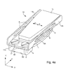
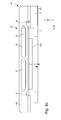
- FIGs 4a and 4b show an embodiment of the vibrating device 10 for carrying out the training method according to the invention.
- the vibrating device presented is of the half Voice Coil type.
- the vibrating device 10 firstly comprises an annular flat coil L, which is fixed at the edge to a non-magnetic structure 5, beneath which two connection terminals B1 and B2 of the coil appear.
- the device further comprises a mobile mass 13a, 13b, 6 and 15 composed of a magnetic structure which is connected to the non-magnetic structure without mechanical contact with the coil by means of a spring element 14.
- the magnetic structure of the mobile mass comprises a ferromagnetic plate 6 on which are fixed two permanent magnets 13a and 13b adjacent direction of opposite magnetization opposite respectively two diametrically opposite portions of the coil.
- the magnets generate a magnetic field B , which is conducted in the ferromagnetic plate 6, in a direction along the Y axis.
- the current flowing in the coil portions is substantially perpendicular. to the magnetic field B in the direction of the Z axis.
- a Laplace force in a direction along the X axis is obtained to oscillate the moving mass in a plane substantially perpendicular to the axis of the coil.
- L in the directions represented O + and O-.
- This complementary plate 15 may be made of a material such as brass or tungsten.
- the spring element 14, which holds the moving mass, comprises a base plate 14c fixed by two screws 17 via a non-magnetic plate 5 'to the non-magnetic structure 5, and two leaf springs 14a and 14b coming from with the base blade and disposed on two opposite sides of the base blade.
- the leaf springs 14a and 14b are arranged perpendicular to the base plate 14c, so that the cross section forms a U.
- the ferromagnetic plate 6 and the complementary plate 15 are placed between the leaf springs 14a and 14b with or without direct contact with each leaf spring.
- the height of the ferromagnetic plate 6 and the complementary plate 15 is less than the height of each leaf spring 14a and 14b.
- the spring blades 14a and 14b may each comprise two longitudinal through slots 8, which are dimensioned to adjust a theoretical resonance frequency of the vibrating device. By this adjustment of this frequency, the driving circuit of the vibrating device can be of relatively simple design.
- the inductance of the coil is much smaller than in the case of a coil mounted on a ferromagnetic yoke as explained in document EP 0 625 738.
- the value of the inductance can be of the order of 1 to 1.5 mH, whereas in the case of a coil mounted on a ferromagnetic yoke, this inductance value can be of the order of 50 mH.
- the induced voltage mainly related to the magnet-coil mutual flux is also lower with this low inductance, and a possible overvoltage of the coil in the measurement phase of the oscillation frequency can be much smaller without damaging the drive circuit .
- the dimensions of such a vibrating device to equip such a wristwatch can be 10 mm long, 4 mm wide and 2 mm high.
- the driving method can also be applied to a vibrating device as presented in document EP 0 625 738.
- a vibrating device As presented in document EP 0 625 738, it is thus not necessary to provide the driving circuit of any filter element, which simplifies the realization of said circuit and reduces the power consumption.
Abstract
Description
La présente invention concerne un procédé d'entraînement d'un dispositif vibrant pour un objet portable. Le dispositif vibrant comprend une masse mobile et une bobine de forme annulaire couplée électro-magnétiquement avec la masse mobile, afin de la faire osciller. Le dispositif vibrant peut servir notamment comme alarme silencieuse ou pour signaler un appel téléphonique.The present invention relates to a method of driving a vibrating device for a portable object. The vibrating device comprises a movable mass and an annular-shaped coil electromagnetically coupled with the moving mass to oscillate it. The vibrating device can serve in particular as a silent alarm or to signal a telephone call.
Il existe plusieurs réalisations de dispositifs vibrants susceptibles de remplir la fonction notamment d'alarme silencieuse afin d'équiper des objets portables de petite taille, tels que des téléphones portables, des organiseurs traditionnels, des dispositifs de recherche de personnes ou des montres-bracelets. Au moins une bobine de ces dispositifs vibrants peut être électriquement activée pour actionner une masse afin de créer une vibration à basse fréquence qui peut être ressentie par le porteur d'un tel objet.There are several embodiments of vibrating devices capable of performing the function including silent alarm to equip small portable objects, such as mobile phones, traditional organizers, paging devices or wristwatches. At least one coil of these vibrating devices can be electrically activated to actuate a mass to create a low frequency vibration that can be felt by the wearer of such an object.
Généralement la fréquence des signaux électriques appliqués à la bobine est ajustée pour correspondre à la fréquence propre d'oscillation mécanique de la masse mobile du dispositif vibrant. De cette manière, une amplitude de vibration maximale peut être obtenue pour une quantité d'énergie électrique minimale fournie. La vibration du dispositif peut être commandée en fonction d'une programmation spécifique de l'objet portable de manière à avertir son porteur d'un événement spécifique, par exemple une heure de réveil, un appel téléphonique ou autre.Generally the frequency of the electrical signals applied to the coil is adjusted to correspond to the natural frequency of mechanical oscillation of the moving mass of the vibrating device. In this way, a maximum vibration amplitude can be obtained for a minimum amount of electrical energy supplied. The vibration of the device can be controlled according to a specific programming of the portable object so as to warn the wearer of a specific event, such as a wake-up time, a phone call or other.
On peut citer à ce titre le document WO 02/46847, qui décrit un procédé d'entraînement d'un tel dispositif vibrant. Le dispositif vibrant comprend une masse mobile ayant un aimant permanent et une bobine couplée électro-magnétiquement à la masse mobile pour la faire osciller. Pour faire osciller la masse, un circuit d'entraînement doit fournir à la bobine du dispositif vibrant des impulsions rectangulaires de tension d'entretien de polarité alternée et de durée déterminée après une phase de démarrage du dispositif vibrant. L'amplitude des impulsions d'entretien correspond approximativement à la tension de pile alimentant électriquement le circuit d'entraînement.In this respect, mention may be made of WO 02/46847, which describes a method of driving such a vibrating device. The vibrating device comprises a moving mass having a permanent magnet and a coil electromagnetically coupled to the moving mass to oscillate it. To oscillate the mass, a driving circuit must provide the coil of the vibrating device with rectangular pulses of maintenance voltage alternating polarity and duration determined after a starting phase of the vibrating device. The amplitude of the maintenance pulses corresponds approximately to the battery voltage electrically supplying the drive circuit.
Entre chaque impulsion de tension d'entretien, la bobine est déconnectée, c'est-à-dire qu'elle est placée dans un état haute impédance. Dans cet état, la bobine fournit une tension induite due au mouvement de l'aimant permanent de la masse oscillante. Une mesure de la fréquence de résonance est opérée à chaque passage par zéro de la tension induite dans le circuit d'entraînement afin d'ajuster la période des impulsions rectangulaires d'entretien fournies à la bobine.Between each maintenance voltage pulse, the coil is disconnected, i.e. it is placed in a high impedance state. In this state, the coil provides an induced voltage due to the movement of the permanent magnet of the oscillating mass. A measurement of the resonance frequency is made at each pass by zero of the induced voltage in the drive circuit to adjust the period of the rectangular maintenance pulses supplied to the coil.
Un inconvénient d'un tel procédé d'entraînement est qu'à chaque déconnexion de la bobine placée à l'état haute impédance, des surtensions, dont la constante de temps est dépendante des caractéristiques de la bobine, peuvent être observées. Ces surtensions peuvent endommager le circuit électronique d'entraînement ou d'alimentation. De plus avec ces surtensions, il doit être observé, avant la mesure de la fréquence, un temps de carence important, qui peut être de l'ordre de quelques centaines de microsecondes afin de ne pas détecter des passages par zéro intempestifs. Ce temps de carence, qui doit être observé, limite la fréquence d'oscillation à une valeur basse. Il est donc nécessaire de filtrer ces surtensions par des moyens adéquats soit à l'entrée d'un comparateur amplificateur du circuit, soit à la sortie du comparateur. Ceci implique de munir le circuit d'entraînement de composants électroniques supplémentaires à la fonction propre d'entretien des oscillations de la masse mobile, ce qui complique la réalisation dudit circuit.A disadvantage of such a drive method is that at each disconnection of the coil placed in the high impedance state, overvoltages, whose time constant is dependent on the characteristics of the coil, can be observed. These overvoltages can damage the drive or power electronics. Moreover with these overvoltages, it must be observed, before the measurement of the frequency, a long time of deficiency, which can be of the order of a few hundred microseconds so as not to detect unwanted zero crossings. This waiting time, which must be observed, limits the oscillation frequency to a low value. It is therefore necessary to filter these overvoltages by adequate means either at the input of an amplifier comparator of the circuit, or at the output of the comparator. This involves providing the drive circuit of additional electronic components to the proper maintenance function oscillations of the moving mass, which complicates the realization of said circuit.
Un autre inconvénient du procédé d'entraînement du document WO 02/46847 est que les impulsions de tension d'entretien sont composées d'une fréquence fondamentale f0 et de fréquences harmoniques f1, f2, qui créent des pertes de puissance et des forces parasites, et qui s'opposent à la force active d'entraînement de la masse oscillante. De ce fait, une consommation électrique plus importante est constatée. Dans le cas d'une tension de pile déterminée, l'amplitude du signal à fréquence fondamentale relative aux impulsions rectangulaires d'entretien est à un niveau de tension qui peut être d'un tiers inférieur à la tension de pile, et ne peut ainsi pas être adaptée à une valeur plus élevée.Another disadvantage of the training method of WO 02/46847 is that the maintenance voltage pulses are composed of a fundamental frequency f 0 and harmonic frequencies f 1 , f 2 , which create power losses and losses. parasitic forces, and which oppose the active driving force of the oscillating mass. As a result, a higher power consumption is noted. In the case of a determined battery voltage, the amplitude of the fundamental frequency signal relative to the rectangular maintenance pulses is at a voltage level which may be one third lower than the battery voltage, and thus can not not be adapted to a higher value.
L'invention a donc pour but principal de pallier les inconvénients cités ci-dessus en réalisant un procédé d'entraînement d'un dispositif vibrant à l'aide de signaux électriques fournis à la bobine du dispositif, qui sont adaptés pour éviter des surtensions dans une phase d'entretien des oscillations de la masse mobile du dispositif. De plus, les harmoniques de la fréquence fondamentale, notamment les harmoniques de faible ordre, sont supprimées par l'intermédiaire des signaux électriques, car seule la composante fondamentale des signaux électriques fournis à la bobine fournit une force utile.The main purpose of the invention is therefore to overcome the drawbacks mentioned above by providing a method of driving a vibrating device by means of electrical signals supplied to the coil of the device, which are adapted to avoid overvoltages in a maintenance phase oscillations of the mobile mass of the device. In addition, the harmonics of the fundamental frequency, in particular the low-order harmonics, are suppressed via the electrical signals, since only the fundamental component of the electrical signals supplied to the coil provides a useful force.
A cet effet, l'invention concerne un procédé d'entraînement d'un dispositif vibrant cité ci-devant qui se caractérise en ce que dans une phase d'entretien des oscillations périodiques de la masse mobile, le procédé consiste à fournir des impulsions rectangulaires successives de tension de polarité alternée sans interruption entre chaque impulsion à la bobine à l'aide d'un circuit d'entraînement connecté à des bornes de la bobine du dispositif vibrant, la largeur des impulsions successives étant modulée de manière sensiblement similaire au cours de chaque période d'oscillation successive afin de définir une onde de tension sensiblement sinusoïdale d'amplitude déterminée dont la fréquence fondamentale est adaptée à la fréquence de résonance de la masse mobile.To this end, the invention relates to a driving method of a vibrating device cited above which is characterized in that in a maintenance phase of the periodic oscillations of the moving mass, the method consists in providing rectangular pulses. successive alternating polarity voltage without interruption between each pulse to the coil by means of a driving circuit connected to terminals of the coil of the vibrating device, the width of the successive pulses being modulated in a substantially similar manner during each successive oscillation period in order to define a substantially sinusoidal voltage wave of determined amplitude whose fundamental frequency is adapted to the frequency of resonance of the moving mass.
Un avantage du procédé selon l'invention réside dans le fait que la modulation de la largeur des impulsions de tension de polarité alternée dans chaque période d'oscillation permet de s'approcher d'un signal pseudo-sinusoïdal de fréquence fondamentale. Par ce fait, il est ainsi possible d'éliminer les harmoniques de la fréquence fondamentale en définissant une onde sensiblement sinusoïdale à l'aide de l'agencement desdites impulsions de tension dans chaque période d'oscillation. Principalement, les harmoniques de faible ordre (3, 5, 7, 9) sont éliminées, car elles conduisent à générer des forces indésirables.An advantage of the method according to the invention lies in the fact that the modulation of the width of the alternating polarity voltage pulses in each oscillation period makes it possible to approach a pseudo-sinusoidal signal of fundamental frequency. As a result, it is thus possible to eliminate the harmonics of the fundamental frequency by defining a substantially sinusoidal wave by means of the arrangement of said voltage pulses in each oscillation period. Mainly, low-order harmonics (3, 5, 7, 9) are eliminated because they lead to undesirable forces.
Comme la masse mobile décrit un mouvement sinusoïdal par rapport à la bobine fixe du dispositif vibrant, il est donc avantageux d'alimenter ladite bobine par une onde de tension sensiblement sinusoïdale définie par l'agencement des impulsions rectangulaires de tension de largeur modulée. La fréquence fondamentale de cette onde sinusoïdale est adaptée à la fréquence de résonance de la masse mobile. Cela permet donc d'éliminer également des harmoniques de forces indésirables, et des pertes de puissance.Since the moving mass describes a sinusoidal movement with respect to the fixed coil of the vibrating device, it is therefore advantageous to supply said coil with a substantially sinusoidal voltage wave defined by the arrangement of the modulated width voltage rectangular pulses. The fundamental frequency of this sine wave is adapted to the resonant frequency of the moving mass. This therefore also eliminates unwanted forces harmonics, and power losses.
Il est à noter que comme il est difficile de réaliser un circuit d'entraînement susceptible d'alimenter directement la bobine du dispositif vibrant avec une onde de tension sinusoïdale, il est beaucoup plus facile de la définir par l'agencement des impulsions rectangulaires successives de tension.It should be noted that since it is difficult to produce a drive circuit capable of supplying the coil of the vibrating device directly with a sinusoidal voltage wave, it is much easier to define it by the arrangement of the successive rectangular pulses of voltage.
En alimentant la bobine par des impulsions rectangulaires de tension sans interruption entre chaque impulsion, aucune surtension n'apparaît durant la phase d'entretien des oscillations périodiques de la masse mobile, ce qui est un autre avantage. L'amplitude de l'onde sinusoïdale définie peut être ajustée en fonction de la modulation de la largeur des impulsions dans chaque période d'oscillation entre une valeur proche de la tension d'alimentation du circuit d'entraînement et la masse. De cette manière, l'amplitude des oscillations de la masse mobile peut être ajustée par les impulsions successives de tension de polarité alternée. Un gain dans la consommation électrique peut ainsi être obtenue avec de tels signaux électriques d'alimentation de la bobine par rapport au procédé d'entraînement décrit en référence au document WO 02/46847.By supplying the coil with rectangular pulses of voltage without interruption between each pulse, no overvoltage appears during the maintenance phase of the periodic oscillations of the moving mass, which is another advantage. The amplitude of the defined sine wave can be adjusted according to the modulation of the pulse width in each oscillation period between a value close to the supply voltage of the drive circuit and the ground. In this way, the amplitude of the oscillations of the moving mass can be adjusted by the successive pulses of alternating polarity voltage. A gain in power consumption can thus be obtained with such electrical power supply signals of the coil compared to the drive method described with reference to WO 02/46847.
De préférence pour la suppression des harmoniques, les impulsions rectangulaires successives de tension de polarité alternée sont agencées pour présenter une symétrie paire dans chaque demi période d'oscillation par rapport à un point milieu de la demi période, et une symétrie impaire dans chaque période d'oscillation par rapport à un point milieu de la période d'oscillation. 14 impulsions de tension par période d'oscillation peuvent avantageusement être fournies à la bobine du dispositif vibrant pour éliminer au moins les harmoniques d'ordre 3 et 5.Preferably for the suppression of harmonics, the successive rectangular pulses of alternating polarity voltage are arranged to having even symmetry in each half oscillation period with respect to a mid-point of the half-period, and odd symmetry in each oscillation period with respect to a mid-point of the oscillation period. 14 voltage pulses per oscillation period can advantageously be provided to the coil of the vibrating device to eliminate at least the harmonics of
Les buts, avantages et caractéristiques du procédé d'entraînement du dispositif vibrant pour un objet portable apparaîtront mieux dans la description suivante d'au moins un mode de réalisation de l'invention en liaison avec les dessins dans lesquels :
- la figure 1 représente un circuit d'entraînement du dispositif vibrant pour la mise en oeuvre du procédé d'entraînement selon l'invention,
- la figure 2 représente un graphique de la tension aux bornes de la bobine au cours du temps de différentes phases de mise en vibration de la masse mobile du dispositif vibrant pour la mise en oeuvre du procédé d'entraînement selon l'invention,
- la figure 3 représente un graphique de la modulation de la largeur des impulsions de tension fournies à la bobine dans une période d'oscillation de la masse mobile pour la mise en oeuvre du procédé d'entraînement selon l'invention, et
- les figures 4a et 4b représentent une vue tridimensionnelle et une vue de côté d'un mode de réalisation du dispositif vibrant pour la mise en oeuvre du procédé d'entraînement selon l'invention.
- FIG. 1 represents a drive circuit of the vibrating device for implementing the drive method according to the invention,
- FIG. 2 represents a graph of the voltage across the coil over time of different phases of vibration of the mobile mass of the vibrating device for carrying out the driving method according to the invention,
- FIG. 3 represents a graph of the modulation of the width of the voltage pulses supplied to the coil in a period of oscillation of the mobile mass for carrying out the drive method according to the invention, and
- Figures 4a and 4b show a three-dimensional view and a side view of an embodiment of the vibrating device for carrying out the training method according to the invention.
Dans la description suivante, tous les éléments qui composent le circuit d'entraînement et le dispositif vibrant qui sont bien connus d'un homme du métier dans ce domaine technique, seront expliqués de manière simplifiée. De préférence, le dispositif vibrant et le circuit d'entraînement sont destinés à équiper un objet portable de petite taille, tel qu'une montre-bracelet de manière à fournir une alarme silencieuse par vibration d'une masse mobile du dispositif vibrant.In the following description, all the elements that make up the drive circuit and the vibrating device that are well known to those skilled in this technical field, will be explained in a simplified manner. Preferably, the vibrating device and the driving circuit are intended to equip a small portable object, such as a wristwatch so as to provide a silent alarm by vibration of a moving mass of the vibrating device.
A la figure 1, un circuit d'entraînement 1 est représenté pour la mise en oeuvre du procédé d'entraînement du dispositif vibrant, qui comprend une masse mobile munie d'au moins un aimant permanent et une bobine de forme annulaire. Cette bobine, qui est indiquée par la référence L, est représentée schématiquement sur cette figure 1. Dans le circuit d'entraînement 1, la bobine est connectée par ses deux bornes B1 et B2 à des éléments de commutation N1, N2, P1, P2 qui forment un pont en H expliqué ci-dessous.In Figure 1, a
Pour son alimentation électrique, le circuit d'entraînement 1 est connecté par ses deux bornes VBAT et Vss à une source de tension non représentée, qui est de préférence une pile ou une batterie pouvant délivrer une tension continue de 3 V par exemple. Lors d'une commande de vibration du dispositif vibrant, les première B1 et deuxième B2 bornes de la bobine L sont susceptibles d'être portées à une tension nulle (masse VSS) ou à une tension VBAT en fonction des états des éléments de commutation N1, N2, P1, P2.For its power supply, the
Les éléments de commutation sont de préférence constitués par quatre transistors de type MOS N1, N2, P1, P2, qui forment un pont en H afin de permettre de commander le dispositif vibrant dans un mode bipolaire. Le pont en H comprend ainsi une première et une seconde branche comprenant les transistors N1 et P1, respectivement les transistors N2 et P2, qui sont montés en série entre les tensions VBAT et VSS. Plus spécifiquement, les transistors P1 et P2 sont des transistors MOS de type P, et les transistors N1 et N2 des transistors MOS de type N. Comme on peut le voir sur la figure 1, la première borne B1 de la bobine L est connectée au noeud de connexion des transistors N1 et P1, et la deuxième borne B2 est connectée au noeud de connexion des transistors N2 et P2.The switching elements are preferably constituted by four MOS transistors N1, N2, P1, P2 which form an H-bridge so as to enable the vibrating device to be controlled in a bipolar mode. The H bridge thus comprises a first and a second branch comprising the transistors N1 and P1, respectively the transistors N2 and P2, which are connected in series between the voltages V BAT and V SS . More specifically, the transistors P1 and P2 are P-type MOS transistors, and the N1 and N2 transistors of the N-type MOS transistors. As can be seen in FIG. 1, the first terminal B1 of the coil L is connected to the connecting node of the transistors N1 and P1, and the second terminal B2 is connected to the connection node of the transistors N2 and P2.
Les grilles des transistors P1, N1, P2, N2 sont respectivement commandés par des signaux A, B, C et D produits par un circuit logique 3 et expliqués ci-après.The gates of the transistors P1, N1, P2, N2 are respectively controlled by signals A, B, C and D produced by a
Pour réaliser une mesure de la fréquence d'oscillation ou de résonance de la masse mobile en mouvement, le circuit d'entraînement comprend un comparateur 2 constitué d'un amplificateur différentiel. Cette fréquence peut se situer entre 132 à 138 Hz. Pour ce faire, les première et deuxième bornes B1, B2 de la bobine L sont respectivement reliées aux bornes non-inverseuse (borne positive) et inverseuse (borne négative) du comparateur 2. Ce comparateur 2 est chargé d'amplifier et de restituer en sortie la tension induite de mouvement de la masse mobile mesurée entre les bornes B1, B2 de la bobine L, lorsqu'elle est mise dans un état haute impédance.To measure the oscillation or resonance frequency of the moving moving mass, the drive circuit comprises a
Cette tension induite de mouvement est appliquée à l'entrée du circuit logique 3 chargé, d'une part, de générer les signaux de commande A, B, C, D nécessaires aux transistors N1, N2, P1, P2 du pont en H. Ces signaux de commande doivent assurer la génération d'au moins une impulsion rectangulaire de tension de démarrage à la bobine L, ainsi que des impulsions rectangulaires successives de tension de polarité alternée à largeur modulée dans une phase d'entretien des oscillations périodiques de la masse mobile. D'autre part, le circuit logique 3 est chargé de mesurer la fréquence de la tension induite issue du comparateur 2.This induced motion voltage is applied to the input of the
On ne s'attardera pas longuement sur la réalisation du circuit logique 3. L'homme du métier pourra se référer à la demande européenne EP 0 938 034, qui est incorporée ici par référence, pour obtenir les informations nécessaires lui permettant de réaliser concrètement le circuit d'entraînement 1 avec le circuit logique 3 sur la base des indications qui lui sont fournies ci-après.We will not spend much time on the realization of the
Comme illustré dans la figure 1, le circuit d'entraînement 1 comprend par ailleurs avantageusement un diviseur de tension enclenchable, qui est chargé d'imposer une tension déterminée sur l'entrée inverseuse (entrée négative) du comparateur 2. Ce diviseur de tension, ici sous la forme d'un diviseur résistif, forme un moyen permettant de fixer l'entrée négative du comparateur 2 à un potentiel déterminé, lorsque la tension induite de mouvement de la masse mobile doit être observée uniquement dans une phase de mesure de la fréquence de résonance. Cette mesure de fréquence doit être réalisée quand la bobine L est placée dans un état haute impédance, c'est-à-dire quand les transistors N1, N2, P1 et P2 sont dans un état non conducteur. Ce diviseur résistif est déclenché dans les autres phases.As illustrated in FIG. 1, the
Plus spécifiquement, le diviseur résistif comprend un agencement en série entre les tensions VBAT et VSS, d'un premier transistor P-MOS P3, d'une première et seconde résistances R1 et R2, et d'un second transistor N-MOS N3. Le noeud de connexion entre les résistances R1 et R2 est relié à l'entrée inverseuse du comparateur 2 et les grilles des transistors P3 et N3 sont reliées au circuit logique 3.More specifically, the resistive divider comprises a series arrangement between the voltages V BAT and V SS , a first P-MOS transistor P3, a first and second resistor R 1 and R 2 , and a second transistor N -MOS N3. The connection node between the resistors R 1 and R 2 is connected to the inverting input of the
Dans cet exemple de réalisation, on peut choisir par exemple de fixer le potentiel de la borne inverseuse du comparateur 2 à une tension égale à VBAT/2 en utilisant pour ce faire des résistances R1 et R2 de valeurs sensiblement égales. Lorsque la bobine L est à l'état haute impédance, c'est-à-dire lorsque les transistors N1, N2, P1 et P2 du pont en H sont tous à l'état non-conducteur, le diviseur résistif est ainsi enclenché par l'activation des transistors P3 et N3 et une tension sensiblement égale à VBAT/2 est appliquée à l'entrée inverseuse du comparateur 2. De la sorte, la valeur moyenne de la tension induite est fixée à ce niveau VBAT/2.In this exemplary embodiment, it is possible, for example, to set the potential of the inverting terminal of the
En référençant la tension induite de mouvement de la masse mobile par rapport au niveau VBAT/2, on assure que la tension induite de mouvement est toujours positive, son amplitude crête à crête étant inférieure à la tension VBAT. Dans l'exemple de réalisation qui est décrit dans la présente demande, on comprendra que la tension induite de mouvement est échantillonnée à une fréquence déterminée. En fixant la valeur moyenne de la tension induite de mouvement à ce niveau VBAT/2, tous les échantillons du signal sont ainsi positifs.By referencing the induced voltage of movement of the moving mass with respect to the level V BAT / 2, it is ensured that the induced motion voltage is always positive, its peak-to-peak amplitude being lower than the voltage V BAT . In the exemplary embodiment described in the present application, it will be understood that the induced motion voltage is sampled at a determined frequency. By setting the average value of the induced motion voltage at this level V BAT / 2, all the samples of the signal are thus positive.
On comprendra aisément, que l'utilisation du diviseur résistif n'est pas strictement nécessaire. On comprendra également qu'un autre niveau moyen que VBAT/2 pourrait être fixé par le diviseur résistif. L'exemple qui est présenté ici est particulièrement avantageux dans l'optique où il est désirable d'effectuer un traitement numérique du signal produit en sortie du comparateur 2.It will be readily understood that the use of the resistive divider is not strictly necessary. It will also be understood that another average level than V BAT / 2 could be set by the resistive divider. The example which is presented here is particularly advantageous in the optic where it is desirable to perform a digital processing of the signal produced at the output of the
Dans la phase de mesure de la fréquence d'oscillation, il peut être employé une autre technique de mesure que celle expliquée ci-dessus. Il peut être effectué une opération de mesure du courant par scanning jusqu'à obtenir une valeur minimale de courant.In the measurement phase of the oscillation frequency, another measurement technique can be used than that explained above. A scanning current measurement operation can be performed until a minimum current value is obtained.
A la figure 2, il est représenté schématiquement différentes phases de mise en route du dispositif vibrant pour la mise en oeuvre du procédé d'entraînement selon l'invention. Plus spécifiquement, il est représenté l'évolution de la tension VB12 aux bornes de la bobine du dispositif vibrant au cours du temps. Dans une première phase, dite phase de démarrage, une impulsion rectangulaire de tension de démarrage est fournie à la bobine.In FIG. 2, diagrammatically different start-up phases of the vibrating device for carrying out the training method according to the invention are shown. More specifically, it is represented the evolution of the voltage V B12 across the coil of the vibrating device over time. In a first phase, called the start-up phase, a rectangular pulse of starting voltage is supplied to the coil.
Cette première phase de démarrage, de mise en mouvement de la masse mobile, est suivie d'une seconde phase, dite phase de mesure de fréquence, durant laquelle la masse mobile du dispositif est laissée en oscillation libre. Durant cette seconde phase, le dispositif tendra à osciller selon sa fréquence propre d'oscillation, ci-après dénommée fréquence d'oscillation ou de résonance f0. Cette fréquence de résonance f0 est par exemple mesurée en déterminant la période d'oscillation T0 de la tension induite générée par le mouvement de la masse durant cette seconde phase sur la base des passages par le niveau moyen de la tension induite de mouvement. Alternativement, on peut se contenter de mesurer la demi période d'oscillation du signal.This first phase of starting, moving the moving mass, is followed by a second phase, called frequency measurement phase, during which the mobile mass of the device is left in free oscillation. During this second phase, the device will tend to oscillate according to its own oscillation frequency, hereinafter called oscillation or resonance frequency f 0 . This resonance frequency f 0 is for example measured by determining the oscillation period T 0 of the induced voltage generated by the movement of the mass during this second phase on the basis of the passages by the average level of the induced motion voltage. Alternatively, it is sufficient to measure the half oscillation period of the signal.
Cette seconde phase de mesure n'est pas strictement nécessaire car la période nominale T0 peut être fixée au préalable si besoin est. Toutefois, comme la valeur de la fréquence de résonance est dépendante également des conditions de porter de l'objet portable, tel qu'une montre-bracelet, et d'un coefficient de frottement visqueux, il est préférable de la mesurer à l'aide du circuit d'entraînement. Cette mesure permet d'ajuster la période d'oscillation d'un ensemble d'impulsions rectangulaires de tension fournies à la bobine.This second measurement phase is not strictly necessary because the nominal period T 0 can be fixed beforehand if necessary. However, since the value of the resonance frequency is also dependent on the wearing conditions of the portable object, such as a wristwatch, and a viscous coefficient of friction, it is preferable to measure it using of the training circuit. This measurement makes it possible to adjust the oscillation period of a set of rectangular voltage pulses supplied to the coil.
Une fois la période d'oscillation T0 déterminée ou fixée, le dispositif vibrant entre dans une troisième phase, dite phase d'entretien des oscillations périodiques de la masse mobile, qui se prolonge jusqu'au terme de la mise en vibration du dispositif. Durant cette troisième phase, des impulsions rectangulaires successives de tension de polarité alternée sont fournies à la bobine. La largeur des impulsions varie ou est modulée par période d'oscillation de manière à définir une onde de tension pseudo-sinusoïdale à fréquence fondamentale. Cette fréquence fondamentale est censée correspondre à la fréquence de résonance de la masse mobile du dispositif vibrant.Once the oscillation period T 0 determined or fixed, the vibrating device enters a third phase, called maintenance phase of the periodic oscillations of the moving mass, which continues until the end of the vibration of the device. During this third phase, successive rectangular pulses of alternating polarity voltage are supplied to the coil. The width of the pulses varies or is modulated by oscillation period so as to define a pseudo-sinusoidal voltage wave at a fundamental frequency. This fundamental frequency is supposed to correspond to the resonant frequency of the moving mass of the vibrating device.
A la figure 3, il est représenté un graphique de la modulation de la largeur des impulsions de tension de polarité alternée, qui sont fournies à la bobine dans chaque période d'oscillation de la masse mobile pour la mise en oeuvre du procédé d'entraînement selon l'invention. Cette modulation de largeur d'impulsions est de préférence identique dans toutes les périodes d'oscillation jusqu'au terme de la mise en vibration du dispositif vibrant. Ce graphique représente donc une période T0 d'oscillation définie sous forme angulaire de 0 à 360°. L'inversion de signe de chaque impulsion est déterminée préférentiellement par un angle spécifique compris entre 0 et 360° étant donné que la fréquence de résonance mesurée peut varier en fonction des conditions de porter de l'objet portable. Cependant après la mesure de fréquence de la deuxième phase, cette fréquence de résonance est déterminée en principe pour toute la durée de vibration du dispositif vibrant.FIG. 3 shows a graph of the modulation of the width of the alternating polarity voltage pulses, which are supplied to the coil in each oscillation period of the moving mass for the implementation of the training method. according to the invention. This pulse width modulation is preferably identical in all the periods of oscillation until the end of the vibration of the vibrating device. This graph represents a period T 0 oscillation defined in angular form from 0 to 360 °. The sign inversion of each pulse is preferably determined by a specific angle between 0 and 360 ° since the measured resonant frequency may vary depending on the wearing conditions of the portable object. However, after the frequency measurement of the second phase, this resonance frequency is determined in principle for the entire vibration duration of the vibrating device.
Pour l'entraînement du dispositif vibrant selon l'invention, il est utilisé un procédé d'élimination des harmoniques d'ordre supérieur à 1 et de contrôle de l'amplitude du fondamental. En effet comme mentionné précédemment, les harmoniques d'ordre 3, 5, 7 et supérieures sont à l'origine des pertes dans la bobine et dans des parties en fer du dispositif vibrant. En éliminant ces harmoniques et en contrôlant l'onde de tension à fréquence fondamentale ainsi définie, on tend à s'approcher d'une tension sinusoïdale d'amplitude souhaitée.For driving the vibrating device according to the invention, it is used a method of eliminating harmonics of order greater than 1 and controlling the amplitude of the fundamental. Indeed, as mentioned above, the harmonics of
De manière simple, il est possible d'éliminer notamment les harmoniques 3 et 5 par une modulation ou pseudo modulation de largeur d'impulsions comme représentée à la figure 2 sur une période temporelle d'oscillation définie sous la forme angulaire de 0 à 360°. La période d'oscillation présente une symétrie paire dans chaque demi période d'oscillation T0/2 ou 180° par rapport à un point milieu de la demi période T0/4 ou 90°. Cette période d'oscillation présente une symétrie impaire des impulsions par rapport à un point milieu de la période d'oscillation, c'est-à-dire par rapport à T0/2 ou 180°. Sur la première demi période, les inversions de signe pour les impulsions rectangulaires successives ont lieu pour les valeurs d'angles a1, a2 et a3, et (180°-a3), (180°-a2) et (1800-a1). La seconde demi période est définie sur la base des angles de la première demi période mais avec des impulsions de polarité inverse. Cette forme d'onde permet d'éliminer un nombre discret d'harmoniques tout en imposant une amplitude déterminée de l'onde à fréquence fondamentale.In a simple manner, it is possible to eliminate in particular the
Dans les tableaux ci-dessous, il est représenté différentes valeurs des angles en fonction de l'amplitude désirée de l'onde sinusoïdale à fréquence fondamentale définie représentée par la courbe SF. L'amplitude du fondamental peut varier entre 1.06 et 0.5 fois la tension de la pile suivant les valeurs d'angles choisies :
Par le choix de l'amplitude du fondamental, c'est-à-dire de l'amplitude de l'onde sinusoïdale définie par la modulation de largeur des impulsions rectangulaires de tension de polarité alternée, il est possible de régler également l'amplitude d'oscillation de la masse mobile du dispositif vibrant. Ceci peut être souhaitable dans certaines configurations de l'objet portable, tel que dans une montre-bracelet de petit volume. Avec les tableaux des angles déterminés en fonction de l'amplitude du fondamental désiré, il est facile de calculer des valeurs temporelles de la largeur de chaque impulsion à l'aide d'une règle de trois en fonction de la valeur de la fréquence d'oscillation. Cette fréquence d'oscillation peut être située dans une gamme de 125 à 140 Hz, de préférence de l'ordre de 135 Hz par exemple.By the choice of the amplitude of the fundamental, that is to say the amplitude of the sine wave defined by the modulation of width of the rectangular pulses of alternating polarity voltage, it is possible to adjust the amplitude as well. oscillation of the moving mass of the vibrating device. This may be desirable in certain configurations of the portable object, such as in a small volume wristwatch. With the tables of the angles determined according to the amplitude of the desired fundamental, it is easy to calculate time values of the width of each pulse by means of a rule of three as a function of the value of the frequency of oscillation. This oscillation frequency can be in a range of 125 to 140 Hz, preferably of the order of 135 Hz for example.
Les figures 4a et 4b représentent un mode de réalisation du dispositif vibrant 10 pour la mise en oeuvre du procédé d'entraînement selon l'invention. Le dispositif vibrant présenté est du type demi Voice Coil. Le dispositif vibrant 10 comprend tout d'abord une bobine plate annulaire L, qui est fixée en bordure à une structure amagnétique 5, au-dessous de laquelle apparaissent deux bornes de connexion B1 et B2 de la bobine. Le dispositif comprend encore une masse mobile 13a, 13b, 6 et 15 composée d'une structure magnétique qui est reliée à la structure amagnétique sans contact mécanique avec la bobine à l'aide d'un élément ressort 14.Figures 4a and 4b show an embodiment of the vibrating
La structure magnétique de la masse mobile comprend une plaque ferromagnétique 6 sur laquelle sont fixés deux aimants permanents 13a et 13b adjacents de direction de magnétisation opposée en regard respectivement de deux portions diamétralement opposées de la bobine. Les aimants génèrent un champ magnétique B, qui est conduit dans la plaque ferromagnétique 6, dans une direction selon l'axe Y. Lorsque la bobine est alimentée par les impulsions rectangulaires successives de tension, le courant passant dans les portions de bobine est sensiblement perpendiculaire au champ magnétique B dans la direction de l'axe Z. De ce fait, une force de Laplace dans une direction selon l'axe X est obtenue afin de faire osciller la masse mobile dans un plan sensiblement perpendiculaire à l'axe de la bobine L dans les directions représentées O+ et O-.The magnetic structure of the mobile mass comprises a
Pour obtenir une masse plus importante, il peut être prévu de placer une plaque de masse complémentaire 15 sur la plaque ferromagnétique 6. Cette plaque complémentaire 15 peut être réalisée dans un matériau tel qu'en laiton ou tungstène.To obtain a larger mass, it may be provided to place a
L'élément ressort 14, qui maintient la masse mobile, comprend une lame de base 14c fixée par deux vis 17 par l'intermédiaire d'une plaque amagnétique 5' sur la structure amagnétique 5, et deux lames ressorts 14a et 14b venant de matière avec la lame de base et disposées sur deux côtés opposés de la lame de base. Les lames ressorts 14a et 14b sont disposées perpendiculairement par rapport à la lame de base 14c, de manière que la section transversale forme un U. Une lame d'extrémité, non représentée, relie les extrémités des lames ressorts 14a et 14b opposées à la lame de base. Cette lame d'extrémité, sur laquelle est fixée une portion de la plaque ferromagnétique 6, est dans un plan sensiblement parallèle à la lame de base.The
La plaque ferromagnétique 6 et la plaque complémentaire 15 sont placées entre les lames ressorts 14a et 14b avec ou sans contact direct avec chaque lame ressort. De préférence, la hauteur de la plaque ferromagnétique 6 et la plaque complémentaire 15 est inférieure à la hauteur de chaque lame ressort 14a et 14b. Les lames ressorts 14a et 14b peuvent comprendre chacune deux fentes traversantes longitudinales 8, qui sont dimensionnées pour ajuster une fréquence de résonance théorique du dispositif vibrant. Par cet ajustement de cette fréquence, le circuit d'entraînement du dispositif vibrant peut être de conception relativement simple.The
Avec le dispositif vibrant tel que présenté aux figures 4a et 4b, l'inductance de la bobine est beaucoup plus faible que dans le cas d'une bobine montée sur une culasse ferromagnétique comme expliqué dans le document EP 0 625 738. La valeur de l'inductance peut être de l'ordre de 1 à 1.5 mH, alors que dans le cas d'une bobine montée sur une culasse ferromagnétique, cette valeur d'inductance peut être de l'ordre de 50 mH. La tension induite liée principalement au flux mutuel aimant-bobine est également plus faible avec cette faible inductance, et une éventuelle surtension de la bobine dans la phase de mesure de la fréquence d'oscillation peut être beaucoup moins importante sans endommager le circuit d'entraînement. Les dimensions d'un tel dispositif vibrant pour équiper notamment une montre-bracelet peuvent être de 10 mm de long, 4 mm de large et 2 mm de hauteur.With the vibrating device as shown in FIGS. 4a and 4b, the inductance of the coil is much smaller than in the case of a coil mounted on a ferromagnetic yoke as explained in
Bien entendu, le procédé d'entraînement peut être appliqué également à un dispositif vibrant tel que présenté dans le document EP 0 625 738. Avec un tel procédé d'entraînement d'un dispositif vibrant, il n'est ainsi pas nécessaire de munir le circuit d'entraînement de tout élément de filtrage, ce qui simplifie la réalisation dudit circuit et permet de réduire la consommation électrique.Of course, the driving method can also be applied to a vibrating device as presented in
A partir de la description qui vient d'être faite de multiples variantes de réalisation du procédé d'entraînement du dispositif vibrant peuvent être conçues par l'homme du métier sans sortir du cadre de l'invention définie par les revendications. Il peut être prévu au cours de la phase d'entretien des oscillations de placer la bobine dans un état haute impédance afin de réajuster la fréquence d'oscillation. Dans chaque période de l'onde sinusoïdale fondamentale, il peut être prévu un nombre plus important d'impulsions modulées de manière à éliminer des harmoniques d'ordre supérieur. Il peut être également prévu dans la phase de démarrage d'imposer deux ou plusieurs impulsions rectangulaires successives de polarité différente avant de placer la bobine à l'état haute impédance.From the description that has just been made of multiple variants of the driving method of the vibrating device can be designed by the skilled person without departing from the scope of the invention defined by the claims. It can be expected during the oscillation maintenance phase to place the coil in a high impedance state in order to readjust the oscillation frequency. In each period of the fundamental sine wave, a larger number of modulated pulses may be provided so as to eliminate higher order harmonics. It can also be provided in the starting phase to impose two or more successive rectangular pulses of different polarity before placing the coil in the high impedance state.
Claims (6)
Priority Applications (1)
| Application Number | Priority Date | Filing Date | Title |
|---|---|---|---|
| EP20050111845 EP1669821B1 (en) | 2004-12-09 | 2005-12-08 | Driving method of a vibrating device for a portable object, with a coil and a moving mass |
Applications Claiming Priority (2)
| Application Number | Priority Date | Filing Date | Title |
|---|---|---|---|
| EP04106436A EP1669820A1 (en) | 2004-12-09 | 2004-12-09 | Driving method of a vibrating device for a portable object, with a coil and a moving mass |
| EP20050111845 EP1669821B1 (en) | 2004-12-09 | 2005-12-08 | Driving method of a vibrating device for a portable object, with a coil and a moving mass |
Publications (2)
| Publication Number | Publication Date |
|---|---|
| EP1669821A1 true EP1669821A1 (en) | 2006-06-14 |
| EP1669821B1 EP1669821B1 (en) | 2011-03-02 |
Family
ID=36284278
Family Applications (1)
| Application Number | Title | Priority Date | Filing Date |
|---|---|---|---|
| EP20050111845 Not-in-force EP1669821B1 (en) | 2004-12-09 | 2005-12-08 | Driving method of a vibrating device for a portable object, with a coil and a moving mass |
Country Status (1)
| Country | Link |
|---|---|
| EP (1) | EP1669821B1 (en) |
Citations (5)
| Publication number | Priority date | Publication date | Assignee | Title |
|---|---|---|---|---|
| US5436622A (en) * | 1993-07-06 | 1995-07-25 | Motorola, Inc. | Variable frequency vibratory alert method and structure |
| EP0938034A1 (en) * | 1998-02-20 | 1999-08-25 | Asulab S.A. | Non-sonic alarm device |
| EP0952663A2 (en) * | 1998-04-23 | 1999-10-27 | Matsushita Electric Works, Ltd. | Driving circuit for oscillatory actuator |
| WO2000038891A2 (en) * | 1998-12-23 | 2000-07-06 | Braun Gmbh | Actuating device for oscillating electric products of personal use, especially electric razors |
| WO2002046847A1 (en) * | 2000-12-05 | 2002-06-13 | Eta Sa Manufacture Horlogere Suisse | Method for maintaining oscillations of a vibrating device and vibrating device using same |
-
2005
- 2005-12-08 EP EP20050111845 patent/EP1669821B1/en not_active Not-in-force
Patent Citations (5)
| Publication number | Priority date | Publication date | Assignee | Title |
|---|---|---|---|---|
| US5436622A (en) * | 1993-07-06 | 1995-07-25 | Motorola, Inc. | Variable frequency vibratory alert method and structure |
| EP0938034A1 (en) * | 1998-02-20 | 1999-08-25 | Asulab S.A. | Non-sonic alarm device |
| EP0952663A2 (en) * | 1998-04-23 | 1999-10-27 | Matsushita Electric Works, Ltd. | Driving circuit for oscillatory actuator |
| WO2000038891A2 (en) * | 1998-12-23 | 2000-07-06 | Braun Gmbh | Actuating device for oscillating electric products of personal use, especially electric razors |
| WO2002046847A1 (en) * | 2000-12-05 | 2002-06-13 | Eta Sa Manufacture Horlogere Suisse | Method for maintaining oscillations of a vibrating device and vibrating device using same |
Also Published As
| Publication number | Publication date |
|---|---|
| EP1669821B1 (en) | 2011-03-02 |
Similar Documents
| Publication | Publication Date | Title |
|---|---|---|
| FR2527345A1 (en) | DEVICE FOR SWITCHING THE SECONDARY MIRROR OF A TELESCOPE | |
| CH321957A (en) | Motor device with electromagnetic pulses applicable in particular to time instruments | |
| FR2501314A1 (en) | ACTIVE REDUNDANT ELECTROMAGNETIC BEARING | |
| CH688952B5 (en) | supply circuit for an electroluminescent sheet. | |
| CH702187A2 (en) | Regulating element for wristwatch and timepiece including such a regulating organ. | |
| EP1521142A1 (en) | Timepiece with a mechanical movement coupled to an electronic regulator mechanism | |
| EP2239842A1 (en) | Amplifier circuit with reduced phase noise | |
| EP1669820A1 (en) | Driving method of a vibrating device for a portable object, with a coil and a moving mass | |
| FR2492607A1 (en) | SPEED CONTROL DEVICE FOR A CONTINUOUS CURRENT MOTOR | |
| EP1669821B1 (en) | Driving method of a vibrating device for a portable object, with a coil and a moving mass | |
| EP1674165A1 (en) | Vibrating device having means for protection against mechanical shocks for a portable device | |
| EP1342132B1 (en) | Method for maintaining oscillations of a vibrating device and vibrating device using same | |
| EP3591475A1 (en) | Thermoelectric watch suitable for being tested in production or after-sales service | |
| EP0558409B1 (en) | Device for generating an electric voltage having a predetermined waveform and iontophoretic transermal drug delivery apparatus, equipped with such a device | |
| EP1659676A1 (en) | Vibrator for a portable device | |
| EP3556006A1 (en) | Piezoelectric actuator type control device for capacitive loads | |
| FR2672712A1 (en) | LASER LIGHT ALTERNATIVE DEFLECTOR FOR BAR CODES READER. | |
| FR2488398A1 (en) | Electromagnetic flowmeter - utilises dipolar excitation current produced intermittently and takes measurement when current is zero | |
| EP4325304A1 (en) | Electromagnetic silent alarm | |
| CH719962A2 (en) | Electromagnetic non-audible vibration alarm. | |
| FR2878335A1 (en) | Electric current sensor for e.g. electric motor, has unit to measure voltage difference, between capacitors, which is product of variable function, independent of sensor`s ambient temperature, and voltage difference between shunt terminals | |
| CH715145A2 (en) | Thermoelectric watch testable in production or after-sales service. | |
| FR3109482A1 (en) | ELEMENTARY CELLS OF AN ELECTRIC MOTOR AND CORRESPONDING ELECTRIC MOTOR | |
| FR2852465A1 (en) | Clock generator for microprocessor and radio communication channel, has pulse forming circuit transforming pilot signal to clock signal with preset duty cycle, and differential amplifier and transistor supplying regulated voltage | |
| EP1674166A2 (en) | Vibrating device having means for protection against mechanical shocks for a portable device |
Legal Events
| Date | Code | Title | Description |
|---|---|---|---|
| PUAI | Public reference made under article 153(3) epc to a published international application that has entered the european phase |
Free format text: ORIGINAL CODE: 0009012 |
|
| AK | Designated contracting states |
Kind code of ref document: A1 Designated state(s): AT BE BG CH CY CZ DE DK EE ES FI FR GB GR HU IE IS IT LI LT LU LV MC NL PL PT RO SE SI SK TR |
|
| AX | Request for extension of the european patent |
Extension state: AL BA HR MK YU |
|
| 17P | Request for examination filed |
Effective date: 20061214 |
|
| 17Q | First examination report despatched |
Effective date: 20070112 |
|
| AKX | Designation fees paid |
Designated state(s): CH DE FI FR LI |
|
| GRAP | Despatch of communication of intention to grant a patent |
Free format text: ORIGINAL CODE: EPIDOSNIGR1 |
|
| GRAS | Grant fee paid |
Free format text: ORIGINAL CODE: EPIDOSNIGR3 |
|
| GRAA | (expected) grant |
Free format text: ORIGINAL CODE: 0009210 |
|
| AK | Designated contracting states |
Kind code of ref document: B1 Designated state(s): CH DE FI FR LI |
|
| REG | Reference to a national code |
Ref country code: CH Ref legal event code: NV Representative=s name: ICB INGENIEURS CONSEILS EN BREVETS SA Ref country code: CH Ref legal event code: EP |
|
| REF | Corresponds to: |
Ref document number: 602005026621 Country of ref document: DE Date of ref document: 20110414 Kind code of ref document: P |
|
| REG | Reference to a national code |
Ref country code: DE Ref legal event code: R096 Ref document number: 602005026621 Country of ref document: DE Effective date: 20110414 |
|
| PG25 | Lapsed in a contracting state [announced via postgrant information from national office to epo] |
Ref country code: FI Free format text: LAPSE BECAUSE OF FAILURE TO SUBMIT A TRANSLATION OF THE DESCRIPTION OR TO PAY THE FEE WITHIN THE PRESCRIBED TIME-LIMIT Effective date: 20110302 |
|
| PLBE | No opposition filed within time limit |
Free format text: ORIGINAL CODE: 0009261 |
|
| STAA | Information on the status of an ep patent application or granted ep patent |
Free format text: STATUS: NO OPPOSITION FILED WITHIN TIME LIMIT |
|
| 26N | No opposition filed |
Effective date: 20111205 |
|
| REG | Reference to a national code |
Ref country code: DE Ref legal event code: R097 Ref document number: 602005026621 Country of ref document: DE Effective date: 20111205 |
|
| PGFP | Annual fee paid to national office [announced via postgrant information from national office to epo] |
Ref country code: CH Payment date: 20131125 Year of fee payment: 9 Ref country code: DE Payment date: 20131121 Year of fee payment: 9 |
|
| PGFP | Annual fee paid to national office [announced via postgrant information from national office to epo] |
Ref country code: FR Payment date: 20131219 Year of fee payment: 9 |
|
| REG | Reference to a national code |
Ref country code: DE Ref legal event code: R119 Ref document number: 602005026621 Country of ref document: DE |
|
| REG | Reference to a national code |
Ref country code: CH Ref legal event code: PL |
|
| REG | Reference to a national code |
Ref country code: FR Ref legal event code: ST Effective date: 20150831 |
|
| PG25 | Lapsed in a contracting state [announced via postgrant information from national office to epo] |
Ref country code: CH Free format text: LAPSE BECAUSE OF NON-PAYMENT OF DUE FEES Effective date: 20141231 Ref country code: LI Free format text: LAPSE BECAUSE OF NON-PAYMENT OF DUE FEES Effective date: 20141231 Ref country code: DE Free format text: LAPSE BECAUSE OF NON-PAYMENT OF DUE FEES Effective date: 20150701 |
|
| PG25 | Lapsed in a contracting state [announced via postgrant information from national office to epo] |
Ref country code: FR Free format text: LAPSE BECAUSE OF NON-PAYMENT OF DUE FEES Effective date: 20141231 |