EP1669785A1 - Camera, interchangeable lens, intermediate adaptor, and camera system including them - Google Patents
Camera, interchangeable lens, intermediate adaptor, and camera system including them Download PDFInfo
- Publication number
- EP1669785A1 EP1669785A1 EP04771148A EP04771148A EP1669785A1 EP 1669785 A1 EP1669785 A1 EP 1669785A1 EP 04771148 A EP04771148 A EP 04771148A EP 04771148 A EP04771148 A EP 04771148A EP 1669785 A1 EP1669785 A1 EP 1669785A1
- Authority
- EP
- European Patent Office
- Prior art keywords
- data
- camera
- intermediate adapter
- interchangeable lens
- adapter
- Prior art date
- Legal status (The legal status is an assumption and is not a legal conclusion. Google has not performed a legal analysis and makes no representation as to the accuracy of the status listed.)
- Granted
Links
- 230000003287 optical effect Effects 0.000 claims abstract description 23
- 238000013500 data storage Methods 0.000 claims abstract description 11
- 238000001514 detection method Methods 0.000 claims abstract 18
- 238000003860 storage Methods 0.000 claims description 20
- 238000004891 communication Methods 0.000 claims description 6
- 230000004907 flux Effects 0.000 claims description 4
- 238000006243 chemical reaction Methods 0.000 claims 1
- 230000009471 action Effects 0.000 description 21
- 238000000034 method Methods 0.000 description 17
- 238000005259 measurement Methods 0.000 description 12
- 230000004044 response Effects 0.000 description 11
- 230000007246 mechanism Effects 0.000 description 8
- 238000012937 correction Methods 0.000 description 7
- 238000003384 imaging method Methods 0.000 description 6
- 230000004075 alteration Effects 0.000 description 5
- 238000012545 processing Methods 0.000 description 5
- 230000001276 controlling effect Effects 0.000 description 4
- 101001018097 Homo sapiens L-selectin Proteins 0.000 description 3
- 102100033467 L-selectin Human genes 0.000 description 3
- 238000010586 diagram Methods 0.000 description 2
- 239000011295 pitch Substances 0.000 description 2
- 238000003825 pressing Methods 0.000 description 2
- -1 DATA Proteins 0.000 description 1
- 238000004364 calculation method Methods 0.000 description 1
- 230000002950 deficient Effects 0.000 description 1
- 238000006073 displacement reaction Methods 0.000 description 1
- 238000005516 engineering process Methods 0.000 description 1
- 230000006870 function Effects 0.000 description 1
- 239000004973 liquid crystal related substance Substances 0.000 description 1
- 238000004519 manufacturing process Methods 0.000 description 1
- 238000012986 modification Methods 0.000 description 1
- 230000004048 modification Effects 0.000 description 1
- 230000002093 peripheral effect Effects 0.000 description 1
Images


Classifications
-
- G—PHYSICS
- G02—OPTICS
- G02B—OPTICAL ELEMENTS, SYSTEMS OR APPARATUS
- G02B15/00—Optical objectives with means for varying the magnification
- G02B15/02—Optical objectives with means for varying the magnification by changing, adding, or subtracting a part of the objective, e.g. convertible objective
- G02B15/10—Optical objectives with means for varying the magnification by changing, adding, or subtracting a part of the objective, e.g. convertible objective by adding a part, e.g. close-up attachment
-
- G—PHYSICS
- G02—OPTICS
- G02B—OPTICAL ELEMENTS, SYSTEMS OR APPARATUS
- G02B7/00—Mountings, adjusting means, or light-tight connections, for optical elements
- G02B7/28—Systems for automatic generation of focusing signals
- G02B7/34—Systems for automatic generation of focusing signals using different areas in a pupil plane
-
- G—PHYSICS
- G03—PHOTOGRAPHY; CINEMATOGRAPHY; ANALOGOUS TECHNIQUES USING WAVES OTHER THAN OPTICAL WAVES; ELECTROGRAPHY; HOLOGRAPHY
- G03B—APPARATUS OR ARRANGEMENTS FOR TAKING PHOTOGRAPHS OR FOR PROJECTING OR VIEWING THEM; APPARATUS OR ARRANGEMENTS EMPLOYING ANALOGOUS TECHNIQUES USING WAVES OTHER THAN OPTICAL WAVES; ACCESSORIES THEREFOR
- G03B17/00—Details of cameras or camera bodies; Accessories therefor
- G03B17/02—Bodies
- G03B17/12—Bodies with means for supporting objectives, supplementary lenses, filters, masks, or turrets
- G03B17/14—Bodies with means for supporting objectives, supplementary lenses, filters, masks, or turrets interchangeably
Definitions
- the present invention relates to a technology of correcting the AF action of a camera in response to a degree of spherical aberration of a camera lens, and particularly to a camera equipped with an AF sensing unit of TTL phase difference type, an interchangeable lens, an intermediate adapter, and a camera system including the same.
- a camera equipped with a TTL phase difference type AF sensing unit yields out-of-focus images when shooting at full open aperture in spite of the lens being adjustably focused on the basis of focusing data detected by the AF sensing unit. This results from a difference in the spherical aberration of the camera lens between a F-number of a full-open aperture and a F-number of AF sensing aperture for measuring the focal point, which thus dislocates the best imaging plane.
- AF correcting data Disclosed in Jpn. Pat. Appln. KOKAI Publication No. 59-208514 is a technique of correcting the output of the AF sensing unit with displacement correcting data of the best imaging plane (referred to as "AF correcting data" hereinafter) which has been decided from a difference in the spherical aberration between two F-numbers and stored in the camera lens.
- a lens interchangeable camera has an intermediate adapter provided between the camera and the interchangeable lens for modifying the focal length.
- the intermediate adapter may be known as a telescopic converter for lengthening the focal length.
- the spherical aberration of the intermediate adapter as well as the spherical aberration of the camera lens has to be concerned for affecting the focal length.
- Jpn. Pat. Appln. KOKAI Publication No. 4-93824 is a technique of correcting the output of the AF sensing unit through using a combination of the two AF correcting data stored in the interchangeable lens and the intermediate adapter respectively.
- the technique disclosed in the Jpn. Pat. Appln. KOKAI Publication No. 4-93824 permits two AF correcting data stored in the interchangeable lens and the intermediate adapter respectively to be simply combined.
- a combination of the interchangeable lens and the intermediate adapter is deficient for improving the accuracy of AF control.
- the AF correcting data shall preferably be decided on the basis of optical characteristics over a combination of the interchangeable lens and the intermediate adapter.
- An object of the present invention is hence to provide a camera, an interchangeable lens, and a camera system including the same, where the action of high-precision AF control can be conducted with the lens interchangeable type camera which is equipped with a TTL phase difference type AF sensor and set by an intermediate adapter to the interchangeable lens.
- a camera system comprising: a TTL phase difference type AF apparatus which is installed in a camera body and which measures a focusing error of an interchangeable lens; a first intermediate adapter detachably set between the camera body and the interchangeable lens for modifying the optical characteristics of the interchangeable lens; a data storage unit which is installed in the interchangeable lens and which stores first data and second data; and a camera CPU installed in the camera body, the camera CPU correcting the measurement of focusing error received from the TTL phase difference type AF apparatus by using the first data when the first intermediate adapter is not set, and correcting the measurement of focusing error received from the TTL phase difference type AF apparatus by using the second data when the first intermediate adapter is set.
- the action of high-precision AF control can be conducted when the camera is set to a combination of the interchangeable lens and the intermediate adapter.
- FIG. 1 is a block diagram showing a typical arrangement of a camera system.
- the camera system consists mainly of an interchangeable lens 10, an intermediate adapter 20, and a camera body unit 30.
- the interchangeable lens 10, the intermediate adapter 20, and the camera body unit 30 are detachably joined together by mounting fittings (not shown).
- the interchangeable lens 10 includes camera lenses 11a and 11b, a diaphragm 12, a lens driving mechanism 13, a diaphragm driving mechanism 14, a lens CPU 15, and a data storage unit 16.
- the lens CPU 15 is provided for exclusively controlling the action of the interchangeable lens 10. More particularly, its control signal is received by the lens driving mechanism 13 which in turn drives the camera lenses 11a and 11b forward and backward for focusing. The control signal is also received by the diaphragm driving mechanism 14 which in turn drives the diaphragm 12 for exposure control. Moreover, the lens CPU 15 exchanges signals of various information with the camera body unit 30.
- the data storage unit 16 is provided for storage of specific information about the lens unit.
- the intermediate adapter 20 includes a telescopic lens 21, an adapter CPU 22, and an adapter storage unit 23.
- the telescopic lens 21 is provided for varying the focal length of the interchangeable lens 10.
- the magnification of the lens can thus be increased, for example, two times by the movement of the telescopic lens 21.
- the adapter storage unit 23 is provided for storage of specific information about the intermediate adapter (for example, the type of lens or the AF correcting data).
- the adapter CPU 22 is provided for exchanging signals with the camera body unit 30 to transmit specific information about the intermediate adapter for AF correcting action.
- the camera body unit 30 consists mainly of a quick return mirror 32, a shutter 33, an imaging device 34, an image processing circuit 35, a camera CPU 36, an image monitor 37, an image memory 38, a camera storage unit 40, a pentagonal prism 41, a light measuring circuit 42, an AF lens 43, a sub mirror 44, an AF sensor 45, a distance meter 46, a shutter driving mechanism 47, and a mirror driving mechanism 48.
- the quick return mirror 32 has a half mirror provided at the center thereof for transmitting an optical image of the object to the pentagonal prism 41 and the AF sensor 45 in a non-shooting mode.
- the imaging device 34 converts the optical image of the object into an electric signal of image data using, for example, CCD.
- the camera CPU 36 is provided for exclusively controlling the action of the camera system and subjecting the image data to a variety of processing actions by controlling the image processing circuit 35. A group of data required for operating the camera CPU 36 is stored in the camera storage unit 40.
- the camera CPU 36 also communicates with the lens CPU 15 in the interchangeable lens 10 and the adapter CPU 22 in the intermediate adapter 20 for receiving the characteristic information of the camera lenses 11a and 11b and the AF correcting information respectively.
- the signal line ASEL is provided for selectively supplying the intermediate adapter 20 with its desired information.
- the signal line LSEL is provided for selectively supplying the interchangeable lens 10 with its desired information.
- the signal line DATA is a common line for supplying the CPUs with the lens characteristic information.
- the signal line CONT is provided for supplying the CPUs with control signals (for example, a demand for lens information or a command for diaphragm driving) from the camera CPU.
- the image monitor 37 may be a liquid crystal display monitor or the like and is provided for displaying an image data.
- the image memory 38 is provided in the form of a recording medium, such as Smart Media (registered trademark), in which the image data is recorded.
- the light measuring circuit 42 is provided for receiving with its optoelectric converter element (not shown) a reflection of the optical image from the pentagonal prism 41 to measure the brightness of the object to be imaged.
- the camera CPU 36 calculates exposure conditions from the measurement of the brightness.
- the AF sensor 45 is provided for receiving the optical image of the object divided in two by the sub mirror 44 and passed through the AF lens 43.
- the distance meter 46 is provided for calculating from an output of the AF sensor 45 the movement of the lens for correct focusing.
- the AF distance meter is of so-called TTL phase difference type in which the flux of light used for measuring the focal point is equivalent to the one with the camera lens aperture stopped down to F8.
- the action starts with a photographer pressing down the release button (not shown) on the camera body unit 30 to its first position.
- the camera CPU 36 calculates the aperture value for an appropriate exposure from brightness of a object to be shot measured by the light measuring circuit 42, and the result is received by the lens CPU 15.
- the lens CPU 15 provides the diaphragm driving mechanism 14 with its output signal for obtaining a desired size of the aperture.
- the camera CPU 36 calculates from the measurement of the distance meter 46, the lens information from the interchangeable lens 10, and the lens information from the intermediate adapter 20 the movement of the camera lenses 11a and 11b which is then received by the lens CPU 15 for correct focusing.
- the lens CPU 15 provides the lens driving mechanism 13 with a control signal for moving the camera lenses 11a and 11b to their correct focusing positions.
- the camera CPU 36 retracts the quick return mirror 32 from the optical path of the camera and actuates the shutter 33 for directing the optical image of the object to the imaging device 34 and subjects the image data output of the imaging device 34 to relevant image processing actions.
- the image processing actions of the camera CPU 36 including color correction are carried out based on the lens information from the interchangeable lens 10 and the lens information from the intermediate adapter 20.
- the camera system of the present invention including the interchangeable lens 10, the intermediate adapter 20, and the camera body unit 30 shown in FIG. 1 is arranged operable in three different variations described below.
- FIG. 2 illustrates the first variation of the camera system of the present invention.
- the first variation of the camera system employs the interchangeable lens 10 and the camera body unit 30.
- the AF correcting data is saved as a combination of a first AF correcting data 16a ( ⁇ AFD0) without the intermediate adapter 20 and a second AF correcting data 16b ( ⁇ AFD1) with the intermediate adapter 20.
- the camera CPU 36 corrects the measurement of focusing error (AFD) of the distance meter 46 calculated by TTL phase difference technique with the AF correcting data, the movement amount of the camera lens for correct focusing is transmitted to the lens CPU 15.
- AFD focusing error
- FIG. 3 illustrates the second variation of the camera system of the present invention.
- the second variation of the camera system employs the interchangeable lens 10, a type A intermediate adapter 20 (a first intermediate adapter) 20a, and the camera body unit 30.
- the type A intermediate adapter 20a means an initial version of the intermediate adapter.
- the AF correcting data is saved as a combination of an AF correcting data 16a ( ⁇ AFD0) without the intermediate adapter 20 and an AF correcting data 16b ( ⁇ AFD1) with the type A intermediate adapter 20a.
- the type A intermediate adapter 20a includes an adapter CPU 22a and an adapter storage unit 23a.
- the adapter storage unit 23a holds a specific information about the intermediate adapter 20a but not the AF correcting data.
- the camera CPU 36 corrects the measurement of focusing error (AFD) of the distance meter 46 calculated by TTL phase difference technique with the AF correcting data, the movement amount of the camera lens for correct focusing is transmitted to the lens CPU 15.
- AFD focusing error
- FIG. 4 illustrates a third variation of the camera system of the present invention.
- the third variation of the camera system employs the interchangeable lens 10, a type B intermediate adapter (a second intermediate adapter) 20b, and the camera body unit 30.
- the type B intermediate adapter 20b means an improved version of the type A intermediate adapter 20a.
- the AF correcting data is saved as a combination of an AF correcting data 16a ( ⁇ AFD0) without the intermediate adapter 20 and an AF correcting data 16b ( ⁇ AFD1) with the type A intermediate adapter 20a.
- the type B intermediate adapter 20b includes an adapter CPU 22b and an adapter storage unit 23b.
- the adapter storage unit 23b holds a correction factor ⁇ or third data used for converting the AF correction data for the type A intermediate adapter 20a into an AF correction data for the type B intermediate adapter 20b.
- the camera CPU 36 corrects the measurement of focusing error (AFD) of the distance meter 46 calculated by TTL phase difference technique with the AF correcting data, the movement amount of the camera lens for correct focusing is transmitted to the lens CPU 15.
- AFD focusing error
- the action of the camera system for AF correction has mainly two steps:
- the camera CPU 36 is designed for functioning with the three different variations of the camera system.
- FIG. 5 is a flowchart schematically showing a procedure of the camera CPU 36 receiving the lens information. The procedure starts when the camera body unit 30 is switched on or set to the interchangeable lens 10 and the intermediate adapter 20.
- step S01 the camera CPU 36 dispatches a lens select signal for receiving the lens information from the interchangeable lens 10. More particularly, the signal line LSEL is turned from a low level to a high level. It is then examined in step S02 whether or not a response is received from the interchangeable lens 10. When the signal line is conducted, the lens CPU 15 releases a response signal indicating that the interchangeable lens 10 is ready for starting the communication.
- step S02 When it is determined “no" in step S02, i.e., no response is received from the interchangeable lens 10, the camera CPU 36 ends the action.
- Step S02 When it is determined “yes” in step S02, i.e., a response is received from the interchangeable lens 10, the action advances to Step S03 where the camera CPU 36 demands to receive the lens information. More specifically, the signal line CONT is conducted for transmitting a lens information demand signal. Upon receiving the demand signal, the lens CPU 15 retrieves the lens information from the data storage unit 16 and transmits the same to the camera CPU.
- the lens information to be transmitted may include the type of lens, the F-number at full opening, and the AF correcting data ( ⁇ AFD0 and ⁇ AFD1).
- the lens information is received by the camera CPU 36 and saved in the camera storage unit 40.
- Step S05 an adapter select signal for receiving the adapter information from the intermediate adapter 20 is dispatched from the camera CPU 36. More particularly, the signal line ASEL is turned from a low level to a high level. It is examined in step S06 whether or not a response is received from the intermediate adapter 20. When the signal line is conducted, the adapter CPU 22 releases a response signal indicating that the intermediate adapter 20 is ready for starting the communication.
- step S06 When it is determined “no" in step S06, i.e., no response is received from the intermediate adapter 20, the camera CPU 36 ends the action of the camera system having an arrangement shown in FIG. 2.
- Step S06 When it is determined “yes” in step S06, i.e., a response is received from the intermediate adapter 20, the action advances to Step S07 where the camera CPU 36 checks the response to identify the type of the intermediate adapter. In other words, the camera CPU 36 examines whether or not the intermediate adapter is of the type B.
- step S08 i.e., the intermediate adapter is of not the type B but the type A such as shown in FIG. 3, the camera CPU 36 ends the action as having received the lens correction data ( ⁇ AFD1) .
- step S08 i.e., the intermediate adapter is of the type B such as shown in FIG. 4, the camera CPU 36 demands to receive the adapter information. More specifically, the signal line CONT is conducted for transmitting an adapter data demand signal. Upon receiving the demand signal, the adapter CPU 22b retrieves the adapter information from the adapter storage unit 23b and transmits the same to the camera CPU 36.
- the adapter data may to be transmitted include the correction factor ⁇ .
- the adapter data is received by the camera CPU 36 and saved in the camera storage unit 40.
- the camera CPU 36 can receive and save the AF correcting data corresponding to each variation of the camera system arrangement in the camera storage unit 40.
- FIG. 6 is a flowchart schematically showing a procedure of the camera CPU 36 calculating the focusing error for correct focusing.
- the procedure involves steps of the AF controlling action initiated prior to shooting action by the photographer pressing down the release button (not shown) on the camera body unit 30.
- step S11 the camera CPU 36 dispatches a command for starting the action of the AF sensor 45.
- step S12 a measurement of focusing error (the number of pitches across the sensor surface) is received from the AF sensor 45.
- step S13 the distance meter 46 calculates the focusing error (AFD) of the camera lenses 11a and 11b from the measurement of the number of pitches.
- AFD focusing error
- step S14 the camera CPU 36 examines whether the intermediate adapter 20 is set or not.
- step S14 When it is determined “no" in step S14, i.e., the intermediate adapter 20 is not set in the camera system shown in FIG. 2, the procedure goes to step S15 where the camera CPU 36 adds the measurement of focusing error (AFD) from the distance meter 46 with the AF correcting data ( ⁇ AFD0) 16a to obtain a focusing error (AFD') at no presence of the intermediate adapter 20.
- step S15 the camera CPU 36 adds the measurement of focusing error (AFD) from the distance meter 46 with the AF correcting data ( ⁇ AFD0) 16a to obtain a focusing error (AFD') at no presence of the intermediate adapter 20.
- AFD focusing error
- Step S14 When it is determined “yes” in step S14, i.e., the intermediate adapter 20 is set, the procedure goes to Step S16 where the camera CPU 36 retrieves the AF correcting data ( ⁇ AFD1) 16b at the presence of the intermediate adapter 20 from the camera storage unit 40.
- ⁇ AFD1 AF correcting data
- step S17 the camera CPU 36 accesses the camera storage unit 40 and examines whether the intermediate adapter is of the type B or not.
- step S17 When it is determined “no" in step S17, i.e., the intermediate adapter is of not the type B but the type A and the camera system is as shown in FIG. 3 where the camera CPU 36 has received the AF correcting data ( ⁇ AFD1) 16b, the procedure goes to Step S18.
- step S18 the camera CPU 36 adds the measurement of focusing error (AFD) from the distance meter 46 with the AF correcting data ( ⁇ AFD1) 16b to obtain a focusing error (AFD') at the presence of the intermediate adapter 20.
- AFD focusing error
- Step S17 When it is determined “yes” in step S17, i.e., the intermediate adapter is of the type B and the camera system is as shown in FIG. 4, the procedure goes to Step S19.
- step S19 the camera CPU 36 retrieves the correcting factor ⁇ from the camera storage unit 40.
- Step S20 the camera CPU 36 adds the measurement of focusing error (AFD) from the distance meter 46 with a multiplication of the AF correcting data ( ⁇ AFD1) 16b by the correcting factor ⁇ to obtain a focusing error (AFD') at the presence of the intermediate adapter 20.
- AFD focusing error
- the corrected focusing error (AFD') is transmitted from the camera CPU 36 to the lens CPU 15 where it is used for driving the camera lenses 11a and 11b to focus correctly.
- the calculation of the corrected focusing error (AFD') in step S20 is not limited to the multiplication of the AF correcting data ( ⁇ AFD1) 16b by the correcting factor ⁇ but may involve addition (or subtraction) of the AF correcting data ( ⁇ AFD1) 16b with the correcting factor ⁇ or use a function in which the AF correcting data ( ⁇ AFD1) 16b and the correcting factor ⁇ are parameters.
- the camera CPU 36 may receive the AF correcting data ( ⁇ AFD1) 16b and the correcting factor ⁇ to be used for AF correcting action not from the interchangeable lens 10 and the intermediate adapter 20 respectively but from any appropriate external peripheral (for example, a server) over a communicating means.
- the present invention is widely applicable to the industry for manufacturing cameras, interchangeable lens, intermediate adapters, and camera systems including the same where the action of high-precision AF control can be conducted.
Landscapes
- Physics & Mathematics (AREA)
- General Physics & Mathematics (AREA)
- Optics & Photonics (AREA)
- Structure And Mechanism Of Cameras (AREA)
- Automatic Focus Adjustment (AREA)
- Studio Devices (AREA)
- Exposure Control For Cameras (AREA)
- Focusing (AREA)
Abstract
Description
- The present invention relates to a technology of correcting the AF action of a camera in response to a degree of spherical aberration of a camera lens, and particularly to a camera equipped with an AF sensing unit of TTL phase difference type, an interchangeable lens, an intermediate adapter, and a camera system including the same.
- It happens that a camera equipped with a TTL phase difference type AF sensing unit yields out-of-focus images when shooting at full open aperture in spite of the lens being adjustably focused on the basis of focusing data detected by the AF sensing unit. This results from a difference in the spherical aberration of the camera lens between a F-number of a full-open aperture and a F-number of AF sensing aperture for measuring the focal point, which thus dislocates the best imaging plane.
- Disclosed in Jpn. Pat. Appln. KOKAI Publication No. 59-208514 is a technique of correcting the output of the AF sensing unit with displacement correcting data of the best imaging plane (referred to as "AF correcting data" hereinafter) which has been decided from a difference in the spherical aberration between two F-numbers and stored in the camera lens.
- A lens interchangeable camera has an intermediate adapter provided between the camera and the interchangeable lens for modifying the focal length. The intermediate adapter may be known as a telescopic converter for lengthening the focal length. When mounted on the camera, the spherical aberration of the intermediate adapter as well as the spherical aberration of the camera lens has to be concerned for affecting the focal length.
- Disclosed in Jpn. Pat. Appln. KOKAI Publication No. 4-93824 is a technique of correcting the output of the AF sensing unit through using a combination of the two AF correcting data stored in the interchangeable lens and the intermediate adapter respectively.
- However, the technique disclosed in the Jpn. Pat. Appln. KOKAI Publication No. 4-93824 permits two AF correcting data stored in the interchangeable lens and the intermediate adapter respectively to be simply combined. Hence, a combination of the interchangeable lens and the intermediate adapter is deficient for improving the accuracy of AF control. For increasing the accuracy of the AF control, the AF correcting data shall preferably be decided on the basis of optical characteristics over a combination of the interchangeable lens and the intermediate adapter.
- An object of the present invention is hence to provide a camera, an interchangeable lens, and a camera system including the same, where the action of high-precision AF control can be conducted with the lens interchangeable type camera which is equipped with a TTL phase difference type AF sensor and set by an intermediate adapter to the interchangeable lens.
- A camera system according to the present invention is provided comprising: a TTL phase difference type AF apparatus which is installed in a camera body and which measures a focusing error of an interchangeable lens; a first intermediate adapter detachably set between the camera body and the interchangeable lens for modifying the optical characteristics of the interchangeable lens; a data storage unit which is installed in the interchangeable lens and which stores first data and second data; and a camera CPU installed in the camera body, the camera CPU correcting the measurement of focusing error received from the TTL phase difference type AF apparatus by using the first data when the first intermediate adapter is not set, and correcting the measurement of focusing error received from the TTL phase difference type AF apparatus by using the second data when the first intermediate adapter is set.
- Accordingly, the action of high-precision AF control can be conducted when the camera is set to a combination of the interchangeable lens and the intermediate adapter.
-
- FIG. 1 is a block diagram showing an arrangement of a camera system.
- FIG. 2 is a view showing a first variation of the camera system according to the invention.
- FIG. 3 is a view showing a second variation of the camera system according to the invention.
- FIG. 4 is a view showing a third variation of the camera system according to the invention.
- FIG. 5 is a flowchart schematically showing a procedure of the camera CPU receiving the lens information.
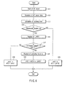
- FIG. 6 is a flowchart schematically showing a procedure of the camera CPU calculating a focusing error correcting data for correct focusing.
- FIG. 1 is a block diagram showing a typical arrangement of a camera system.
- The camera system consists mainly of an
interchangeable lens 10, anintermediate adapter 20, and acamera body unit 30. Theinterchangeable lens 10, theintermediate adapter 20, and thecamera body unit 30 are detachably joined together by mounting fittings (not shown). - The
interchangeable lens 10 includescamera lenses diaphragm 12, alens driving mechanism 13, adiaphragm driving mechanism 14, alens CPU 15, and adata storage unit 16. - The
lens CPU 15 is provided for exclusively controlling the action of theinterchangeable lens 10. More particularly, its control signal is received by thelens driving mechanism 13 which in turn drives thecamera lenses diaphragm driving mechanism 14 which in turn drives thediaphragm 12 for exposure control. Moreover, thelens CPU 15 exchanges signals of various information with thecamera body unit 30. - The
data storage unit 16 is provided for storage of specific information about the lens unit. - The
intermediate adapter 20 includes atelescopic lens 21, anadapter CPU 22, and anadapter storage unit 23. - The
telescopic lens 21 is provided for varying the focal length of theinterchangeable lens 10. The magnification of the lens can thus be increased, for example, two times by the movement of thetelescopic lens 21. - The
adapter storage unit 23 is provided for storage of specific information about the intermediate adapter (for example, the type of lens or the AF correcting data). Theadapter CPU 22 is provided for exchanging signals with thecamera body unit 30 to transmit specific information about the intermediate adapter for AF correcting action. - The
camera body unit 30 consists mainly of aquick return mirror 32, ashutter 33, animaging device 34, animage processing circuit 35, acamera CPU 36, animage monitor 37, animage memory 38, acamera storage unit 40, apentagonal prism 41, alight measuring circuit 42, anAF lens 43, asub mirror 44, anAF sensor 45, adistance meter 46, ashutter driving mechanism 47, and amirror driving mechanism 48. - The
quick return mirror 32 has a half mirror provided at the center thereof for transmitting an optical image of the object to thepentagonal prism 41 and theAF sensor 45 in a non-shooting mode. Theimaging device 34 converts the optical image of the object into an electric signal of image data using, for example, CCD. Thecamera CPU 36 is provided for exclusively controlling the action of the camera system and subjecting the image data to a variety of processing actions by controlling theimage processing circuit 35. A group of data required for operating thecamera CPU 36 is stored in thecamera storage unit 40. - The
camera CPU 36 also communicates with thelens CPU 15 in theinterchangeable lens 10 and theadapter CPU 22 in theintermediate adapter 20 for receiving the characteristic information of thecamera lenses - There are provided four signal lines ASEL, LSEL, DATA, and CONT for exchanging the information. The signal line ASEL is provided for selectively supplying the
intermediate adapter 20 with its desired information. The signal line LSEL is provided for selectively supplying theinterchangeable lens 10 with its desired information. The signal line DATA is a common line for supplying the CPUs with the lens characteristic information. The signal line CONT is provided for supplying the CPUs with control signals (for example, a demand for lens information or a command for diaphragm driving) from the camera CPU. - The
image monitor 37 may be a liquid crystal display monitor or the like and is provided for displaying an image data. Theimage memory 38 is provided in the form of a recording medium, such as Smart Media (registered trademark), in which the image data is recorded. - The
light measuring circuit 42 is provided for receiving with its optoelectric converter element (not shown) a reflection of the optical image from thepentagonal prism 41 to measure the brightness of the object to be imaged. Thecamera CPU 36 calculates exposure conditions from the measurement of the brightness. TheAF sensor 45 is provided for receiving the optical image of the object divided in two by thesub mirror 44 and passed through theAF lens 43. Thedistance meter 46 is provided for calculating from an output of theAF sensor 45 the movement of the lens for correct focusing. The AF distance meter is of so-called TTL phase difference type in which the flux of light used for measuring the focal point is equivalent to the one with the camera lens aperture stopped down to F8. - Then, the action of the camera system will be described.
- The action starts with a photographer pressing down the release button (not shown) on the
camera body unit 30 to its first position. Thecamera CPU 36 then calculates the aperture value for an appropriate exposure from brightness of a object to be shot measured by thelight measuring circuit 42, and the result is received by thelens CPU 15. Thelens CPU 15 provides thediaphragm driving mechanism 14 with its output signal for obtaining a desired size of the aperture. - Also, the
camera CPU 36 calculates from the measurement of thedistance meter 46, the lens information from theinterchangeable lens 10, and the lens information from theintermediate adapter 20 the movement of thecamera lenses lens CPU 15 for correct focusing. In response to the movement data, thelens CPU 15 provides thelens driving mechanism 13 with a control signal for moving thecamera lenses - When the photographer presses down the release button (not shown) on the
camera body unit 30 to its second position, thecamera CPU 36 retracts thequick return mirror 32 from the optical path of the camera and actuates theshutter 33 for directing the optical image of the object to theimaging device 34 and subjects the image data output of theimaging device 34 to relevant image processing actions. The image processing actions of thecamera CPU 36 including color correction are carried out based on the lens information from theinterchangeable lens 10 and the lens information from theintermediate adapter 20. - The camera system of the present invention including the
interchangeable lens 10, theintermediate adapter 20, and thecamera body unit 30 shown in FIG. 1 is arranged operable in three different variations described below. - FIG. 2 illustrates the first variation of the camera system of the present invention. The first variation of the camera system employs the
interchangeable lens 10 and thecamera body unit 30. - In the
data storage unit 16, the AF correcting data is saved as a combination of a firstAF correcting data 16a (ΔAFD0) without theintermediate adapter 20 and a secondAF correcting data 16b (ΔAFD1) with theintermediate adapter 20. - Accordingly, as the
camera CPU 36 corrects the measurement of focusing error (AFD) of thedistance meter 46 calculated by TTL phase difference technique with the AF correcting data, the movement amount of the camera lens for correct focusing is transmitted to thelens CPU 15. - FIG. 3 illustrates the second variation of the camera system of the present invention. The second variation of the camera system employs the
interchangeable lens 10, a type A intermediate adapter 20 (a first intermediate adapter) 20a, and thecamera body unit 30. The type Aintermediate adapter 20a means an initial version of the intermediate adapter. - In the
data storage unit 16, the AF correcting data is saved as a combination of anAF correcting data 16a (ΔAFD0) without theintermediate adapter 20 and anAF correcting data 16b (ΔAFD1) with the type Aintermediate adapter 20a. The type Aintermediate adapter 20a includes an adapter CPU 22a and an adapter storage unit 23a. The adapter storage unit 23a holds a specific information about theintermediate adapter 20a but not the AF correcting data. - Accordingly, as the
camera CPU 36 corrects the measurement of focusing error (AFD) of thedistance meter 46 calculated by TTL phase difference technique with the AF correcting data, the movement amount of the camera lens for correct focusing is transmitted to thelens CPU 15. - FIG. 4 illustrates a third variation of the camera system of the present invention. The third variation of the camera system employs the
interchangeable lens 10, a type B intermediate adapter (a second intermediate adapter) 20b, and thecamera body unit 30. The type Bintermediate adapter 20b means an improved version of the type Aintermediate adapter 20a. - In the
data storage unit 16, the AF correcting data is saved as a combination of anAF correcting data 16a (ΔAFD0) without theintermediate adapter 20 and anAF correcting data 16b (ΔAFD1) with the type Aintermediate adapter 20a. The type Bintermediate adapter 20b includes an adapter CPU 22b and anadapter storage unit 23b. Theadapter storage unit 23b holds a correction factor α or third data used for converting the AF correction data for the type Aintermediate adapter 20a into an AF correction data for the type Bintermediate adapter 20b. - Accordingly, as the
camera CPU 36 corrects the measurement of focusing error (AFD) of thedistance meter 46 calculated by TTL phase difference technique with the AF correcting data, the movement amount of the camera lens for correct focusing is transmitted to thelens CPU 15. - The action of the camera system for AF correction has mainly two steps:
- (1) the
camera CPU 36 in thecamera body unit 30 receiving the lens information from both theinterchangeable lens 10 and theintermediate adapter 20; and - (2) the
camera CPU 36 in thecamera body unit 30 calculating the movement of the lenses for correct focusing. - The two steps will now be described in more detail. The
camera CPU 36 is designed for functioning with the three different variations of the camera system. - FIG. 5 is a flowchart schematically showing a procedure of the
camera CPU 36 receiving the lens information. The procedure starts when thecamera body unit 30 is switched on or set to theinterchangeable lens 10 and theintermediate adapter 20. - In step S01, the
camera CPU 36 dispatches a lens select signal for receiving the lens information from theinterchangeable lens 10. More particularly, the signal line LSEL is turned from a low level to a high level. It is then examined in step S02 whether or not a response is received from theinterchangeable lens 10. When the signal line is conducted, thelens CPU 15 releases a response signal indicating that theinterchangeable lens 10 is ready for starting the communication. - When it is determined "no" in step S02, i.e., no response is received from the
interchangeable lens 10, thecamera CPU 36 ends the action. - When it is determined "yes" in step S02, i.e., a response is received from the
interchangeable lens 10, the action advances to Step S03 where thecamera CPU 36 demands to receive the lens information. More specifically, the signal line CONT is conducted for transmitting a lens information demand signal. Upon receiving the demand signal, thelens CPU 15 retrieves the lens information from thedata storage unit 16 and transmits the same to the camera CPU. - The lens information to be transmitted may include the type of lens, the F-number at full opening, and the AF correcting data (ΔAFD0 and ΔAFD1). In step S04, the lens information is received by the
camera CPU 36 and saved in thecamera storage unit 40. - This is followed by Step S05 where an adapter select signal for receiving the adapter information from the
intermediate adapter 20 is dispatched from thecamera CPU 36. More particularly, the signal line ASEL is turned from a low level to a high level. It is examined in step S06 whether or not a response is received from theintermediate adapter 20. When the signal line is conducted, theadapter CPU 22 releases a response signal indicating that theintermediate adapter 20 is ready for starting the communication. - When it is determined "no" in step S06, i.e., no response is received from the
intermediate adapter 20, thecamera CPU 36 ends the action of the camera system having an arrangement shown in FIG. 2. - When it is determined "yes" in step S06, i.e., a response is received from the
intermediate adapter 20, the action advances to Step S07 where thecamera CPU 36 checks the response to identify the type of the intermediate adapter. In other words, thecamera CPU 36 examines whether or not the intermediate adapter is of the type B. - When it is determined "no" in step S08, i.e., the intermediate adapter is of not the type B but the type A such as shown in FIG. 3, the
camera CPU 36 ends the action as having received the lens correction data (ΔAFD1) . - When it is determined "yes" in step S08, i.e., the intermediate adapter is of the type B such as shown in FIG. 4, the
camera CPU 36 demands to receive the adapter information. More specifically, the signal line CONT is conducted for transmitting an adapter data demand signal. Upon receiving the demand signal, the adapter CPU 22b retrieves the adapter information from theadapter storage unit 23b and transmits the same to thecamera CPU 36. - The adapter data may to be transmitted include the correction factor α. In step S09, the adapter data is received by the
camera CPU 36 and saved in thecamera storage unit 40. - Through conducting the above described procedure, the
camera CPU 36 can receive and save the AF correcting data corresponding to each variation of the camera system arrangement in thecamera storage unit 40. - FIG. 6 is a flowchart schematically showing a procedure of the
camera CPU 36 calculating the focusing error for correct focusing. The procedure involves steps of the AF controlling action initiated prior to shooting action by the photographer pressing down the release button (not shown) on thecamera body unit 30. - In step S11, the
camera CPU 36 dispatches a command for starting the action of theAF sensor 45. In step S12, a measurement of focusing error (the number of pitches across the sensor surface) is received from theAF sensor 45. In step S13, thedistance meter 46 calculates the focusing error (AFD) of thecamera lenses - This is followed by step S14 where the
camera CPU 36 examines whether theintermediate adapter 20 is set or not. - When it is determined "no" in step S14, i.e., the
intermediate adapter 20 is not set in the camera system shown in FIG. 2, the procedure goes to step S15 where thecamera CPU 36 adds the measurement of focusing error (AFD) from thedistance meter 46 with the AF correcting data (ΔAFD0) 16a to obtain a focusing error (AFD') at no presence of theintermediate adapter 20. - When it is determined "yes" in step S14, i.e., the
intermediate adapter 20 is set, the procedure goes to Step S16 where thecamera CPU 36 retrieves the AF correcting data (ΔAFD1) 16b at the presence of theintermediate adapter 20 from thecamera storage unit 40. - In step S17, the
camera CPU 36 accesses thecamera storage unit 40 and examines whether the intermediate adapter is of the type B or not. - When it is determined "no" in step S17, i.e., the intermediate adapter is of not the type B but the type A and the camera system is as shown in FIG. 3 where the
camera CPU 36 has received the AF correcting data (ΔAFD1) 16b, the procedure goes to Step S18. In step S18, thecamera CPU 36 adds the measurement of focusing error (AFD) from thedistance meter 46 with the AF correcting data (ΔAFD1) 16b to obtain a focusing error (AFD') at the presence of theintermediate adapter 20. - When it is determined "yes" in step S17, i.e., the intermediate adapter is of the type B and the camera system is as shown in FIG. 4, the procedure goes to Step S19. In step S19, the
camera CPU 36 retrieves the correcting factor α from thecamera storage unit 40. This is followed by Step S20 where thecamera CPU 36 adds the measurement of focusing error (AFD) from thedistance meter 46 with a multiplication of the AF correcting data (ΔAFD1) 16b by the correcting factor α to obtain a focusing error (AFD') at the presence of theintermediate adapter 20. - Finally, the corrected focusing error (AFD') is transmitted from the
camera CPU 36 to thelens CPU 15 where it is used for driving thecamera lenses - The calculation of the corrected focusing error (AFD') in step S20 is not limited to the multiplication of the AF correcting data (ΔAFD1) 16b by the correcting factor α but may involve addition (or subtraction) of the AF correcting data (ΔAFD1) 16b with the correcting factor α or use a function in which the AF correcting data (ΔAFD1) 16b and the correcting factor α are parameters.
- It is also possible for the
camera CPU 36 to receive the AF correcting data (ΔAFD1) 16b and the correcting factor α to be used for AF correcting action not from theinterchangeable lens 10 and theintermediate adapter 20 respectively but from any appropriate external peripheral (for example, a server) over a communicating means. - While the foregoing embodiment includes different stages of the present invention, it is understood that various modifications are made by different combinations of the stages or disclosed members of the embodiment. For example, even if some members of the embodiment are deleted, the remaining members can overcome the drawbacks described in the paragraph of problems that the invention is to solve and provide the advantages described in the paragraph of the advantages of the invention, thus remaining in the scope of the present invention.
- The present invention is widely applicable to the industry for manufacturing cameras, interchangeable lens, intermediate adapters, and camera systems including the same where the action of high-precision AF control can be conducted.
Claims (34)
- A camera system comprising a camera body and an interchangeable lens detachably set to the camera body, the camera system comprising:a TTL phase difference type AF apparatus which is installed in the camera body and which detects a focusing error of the interchangeable lens;a first intermediate adapter detachably set between the camera body and the interchangeable lens in order to modify the optical characteristics of the interchangeable lens;a data storage unit which is installed in the interchangeable lens and which stores first data and second data; anda camera CPU installed in the camera body, the camera CPU correcting the detection result of focusing error received from the TTL phase difference type AF apparatus by using the first data when the first intermediate adapter is not set, and correcting the detection result of focusing error received from the TTL phase difference type AF apparatus by using the second data when the first intermediate adapter is set.
- A camera system according to claim 1, wherein
the first data depends on the optical characteristics of only the interchangeable lens, and
the second data depends on the optical characteristics of a combination of the interchangeable lens and the first intermediate adapter. - A camera system according to claim 1, wherein
the camera CPU has a function of determining whether the first intermediate adapter is set or not. - A camera system according to claim 1, wherein
the first intermediate adapter includes a first adapter CPU, the first adapter CPU being arranged to communicate with the camera CPU. - A camera system according to claim 4, wherein
the camera CPU determines that the first intermediate adapter is set when its communication with the first adapter CPU is enabled. - A camera system according to claim 1, wherein
the camera CPU corrects with the first or second data a difference between the optimum focal point corresponding to a F-number of full open aperture of the interchangeable lens and the optimum focal point corresponding to a F-number of AF sensing aperture of the TTL phase difference type AF apparatus. - A camera system according to claim 1, wherein a second intermediate adapter which is different from the first intermediate adapter is arranged detachably to be set between the camera body and the interchangeable lens, and the second intermediate adapter is provided for saving third data used for correcting the second data.
- A camera system according to claim 7, wherein
the camera CPU
corrects the detection result of focusing error received from the TTL phase difference type AF apparatus by using the first data when neither the first nor second intermediate adapters is set;
corrects the detection result of focusing error received from the TTL phase difference type AF apparatus by using the second data when the first intermediate adapter is set; and
corrects the detection result of focusing error received from the TTL phase difference type AF apparatus by using both the second and third data when the second intermediate adapter is set. - A camera system according to claim 7, wherein
the first and second intermediate adapters are conversion lenses which change the focal length of the interchangeable lens. - A camera system according to claim 7, wherein
the second intermediate adapter includes a second adapter CPU, the second adapter CPU being arranged to communicate with the camera CPU. - A second intermediate adapter which is applicable to the camera system according to claim 1, and replaces the first intermediate adapter, wherein
the second intermediate adapter has a function of transmitting the third data to correct the second data to the camera CPU. - A second intermediate adapter according to claim 11, having:an adapter storage unit which stores the third data; andan adapter CPU arranged for communication with the camera CPU.
- A camera system comprising a camera body and an interchangeable lens detachably set to the camera body, the camera system comprising:a TTL phase difference type AF apparatus which is installed in the camera body and which detects a focusing error of the interchangeable lens;a first intermediate adapter or a second intermediate adapter detachably set between the camera body and the interchangeable lens in order to modify the optical characteristics of the interchangeable lens;a first storage unit which is installed in the interchangeable lens and which stores first data decided by the optical characteristics of the interchangeable lens and second data decided by the optical characteristics of a combination of the interchangeable lens and the first intermediate adapter;a second storage unit which is installed in the second intermediate adapter and which stores third data to correct the second data; anda camera CPU installed in the camera body, the camera CPU correcting the detection result of focusing error received from the TTL phase difference type AF apparatus by using the first data when neither the first nor second intermediate adapters is set, correcting the detection result of focusing error received from the TTL phase difference type AF apparatus by using the second data when the first intermediate adapter is set, and correcting the detection result of focusing error received from the TTL phase difference type AF apparatus by using both the second and third data when the second intermediate adapter is set.
- A camera system according to claim 13, wherein
when second intermediate adapter is set, the camera CPU corrects the second data by using the third data and then the detection result of focusing error received from the TTL phase difference type AF apparatus by using the corrected second data. - A camera system according to claim 13, wherein
the camera CPU corrects with any of the first data, the second data, or a combination of the second and third data a difference between the optimum focal point corresponding to the F-number of full open aperture of the interchangeable lens and the optimum focal point corresponding to a F-number of AF sensing aperture of the TTL phase difference type AF apparatus. - A camera designed for detachably being set to an interchangeable lens directly or through a first intermediate adapter, comprising:a TTL phase difference type AF apparatus which detects a focusing error of the interchangeable lens; anda camera CPU having a function of reading a first data and second data from the interchangeable lens and a function of correcting the detection result of focusing error received from the TTL phase difference type AF apparatus by using the first data when the first intermediate adapter is not set, and correcting the detection result of focusing error received from the TTL phase difference type AF apparatus by using the second data when the first intermediate adapter is set.
- A camera according to claim 16, wherein
the first data depends on the optical characteristics of only the interchangeable lens, and
the second data depends on the optical characteristics of a combination of the interchangeable lens and the first intermediate adapter. - A camera according to claim 16, wherein
the camera CPU has a function of determining whether the first intermediate adapter is set or not. - A camera according to claim 18, wherein
the camera CPU determines that the first intermediate adapter is set when its communication with an adapter CPU provided in the first intermediate adapter is enabled. - A camera according to claim 16, wherein
the camera CPU corrects with the first or second data a difference between the optimum focal point corresponding to the F-number of full open aperture of the interchangeable lens and the optimum focal point corresponding to a F-number of AF sensing aperture of the TTL phase difference type AF apparatus. - A camera according to claim 16, wherein the first intermediate adapter is replaced by a second intermediate adapter detachably, and the second intermediate adapter is provided for saving third data to correct the second data.
- A camera according to claim 21, wherein
the camera CPU
corrects the detection result of focusing error received from the TTL phase difference type AF apparatus by using the first data when neither the first nor second intermediate adapters is set;
corrects the detection result of focusing error received from the TTL phase difference type AF apparatus by using the second data when the first intermediate adapter is set; and
corrects the detection result of focusing error received from the TTL phase difference type AF apparatus by using both the second and third data when the second intermediate adapter is set. - A camera according to claim 22, wherein
the camera CPU is arranged for communicating with an adapter CPU provided in each of the first and second intermediate adapters and determining from the communication which of the first intermediate adapter and the second intermediate adapter is set. - An interchangeable lens designed for detachably being set to a camera body directly or through an intermediate adapter, comprising:a data storage unit which stores first data that depends on the optical characteristics of only the interchangeable lens and second data that depends on the optical characteristics of a combination of the interchangeable lens and the intermediate adapter, the two data provided as a data to correct an output of a TLL phase difference type AF apparatus installed in the camera body; anda lens CPU which transmits the first data and the second data stored in the data storage unit to a camera CPU installed in the camera body.
- A camera system comprising a camera body and an interchangeable lens detachably set to the camera body, comprising:distance measuring means for measuring a focusing error of the interchangeable lens through detecting a flux of light passed through the interchangeable lens;an intermediate adapter arranged for detachably being set between the camera body and the interchangeable lens;data storing means for storing first data and second data;reading means for reading the first data and the second data from the data storing means; andcorrecting means for correcting the detection result of focusing error received from the distance measuring means by using the first data when the intermediate adapter is not set, and correcting the detection result of focusing error received from the distance measuring means by using the second data when the intermediate adapter is set.
- A camera system according to claim 25, wherein
the camera body has determining means for determining whether the intermediate adapter is set or not. - A camera system according to claim 25, wherein
the data storing means is installed in the interchangeable lens, and
the correcting means is installed in the camera body. - A second intermediate adapter which is applicable to a camera system according to claim 25, and replaces the first intermediate adapter, wherein
the second intermediate adapter has adapter storing means for storing third data to correct the second data and transmitting means for transmitting the third data to the correcting means. - A camera system comprising a camera body and an interchangeable lens detachably set to the camera body, the camera system comprising:distance measuring means for measuring a focusing error of the interchangeable lens through detecting a flux of light passed through the interchangeable lens;a first intermediate adapter and a second intermediate adapter arranged for detachably being set between the camera body and the interchangeable lens;first storing means for storing first data decided by the optical characteristics of the interchangeable lens and second data decided by the optical characteristics of a combination of the interchangeable lens and the first intermediate adapter;second storing means for storing third data to correct the second data; andcorrecting means for correcting the output received from the distance measuring means by using the first data when neither the first nor second intermediate adapters is set, correcting the output received from the distance measuring means by using the second data when the first intermediate adapter is set, and correcting the output received from the distance measuring means by using both the second and third data when the second intermediate adapter is set.
- A camera system according to claim 29, wherein
the correcting means corrects the second data by using the third data when the second intermediate adapter is set and then corrects the output of the distance measuring means by using the corrected second data. - A camera system according to claim 29, wherein
the first data storing means is installed in the interchangeable lens,
the second data storing means is installed in the second intermediate adapter, and
the correcting means is installed in the camera body. - A camera designed for detachably being set to an interchangeable lens directly or through an intermediate adapter, comprising:distance measuring means for measuring a focusing error of the interchangeable lens through detecting a flux of light passed through the interchangeable lens;reading means for reading first data and second data from the interchangeable lens; andcorrecting means for correcting the output of the distance measuring means by using the first data when the intermediate adapter is not set and correcting the output of the distance measuring means by using the second data when the intermediate adapter is set.
- A camera according to claim 32, wherein
the first data depends on the optical characteristics of only the interchangeable lens, and
the second data depends on the optical characteristics of a combination of the interchangeable lens and the intermediate adapter. - A camera according to claim 32, wherein
the camera has determining means for determining whether the intermediate adapter is set or not.
Applications Claiming Priority (2)
| Application Number | Priority Date | Filing Date | Title |
|---|---|---|---|
| JP2003292267A JP2005062459A (en) | 2003-08-12 | 2003-08-12 | Lens interchangeable type camera and camera system |
| PCT/JP2004/011094 WO2005015282A1 (en) | 2003-08-12 | 2004-08-03 | Camera, interchangeable lens, intermediate adaptor, and camera system including them |
Publications (3)
| Publication Number | Publication Date |
|---|---|
| EP1669785A1 true EP1669785A1 (en) | 2006-06-14 |
| EP1669785A4 EP1669785A4 (en) | 2006-07-26 |
| EP1669785B1 EP1669785B1 (en) | 2011-09-28 |
Family
ID=34131709
Family Applications (1)
| Application Number | Title | Priority Date | Filing Date |
|---|---|---|---|
| EP04771148A Expired - Lifetime EP1669785B1 (en) | 2003-08-12 | 2004-08-03 | Camera, interchangeable lens, intermediate adapter, and camera system including them |
Country Status (5)
| Country | Link |
|---|---|
| US (1) | US20050237417A1 (en) |
| EP (1) | EP1669785B1 (en) |
| JP (1) | JP2005062459A (en) |
| CN (1) | CN100345019C (en) |
| WO (1) | WO2005015282A1 (en) |
Families Citing this family (32)
| Publication number | Priority date | Publication date | Assignee | Title |
|---|---|---|---|---|
| JP4717477B2 (en) | 2005-03-07 | 2011-07-06 | 富士フイルム株式会社 | telescope lens |
| JP2007017622A (en) * | 2005-07-06 | 2007-01-25 | Olympus Imaging Corp | Lens interchangeable type imaging apparatus |
| JP2008053843A (en) * | 2006-08-22 | 2008-03-06 | Olympus Imaging Corp | Digital camera capable of recording motion picture |
| JP5034429B2 (en) * | 2006-10-16 | 2012-09-26 | ソニー株式会社 | Lens device, imaging device, and aberration correction method |
| JP5129489B2 (en) * | 2007-02-15 | 2013-01-30 | ペンタックスリコーイメージング株式会社 | Aperture driving device for interchangeable lens digital camera |
| JP4746110B2 (en) | 2007-02-15 | 2011-08-10 | パナソニック株式会社 | Imaging device and camera body |
| JP4905692B2 (en) * | 2007-03-16 | 2012-03-28 | ペンタックスリコーイメージング株式会社 | interchangeable lens |
| CN101925854A (en) * | 2008-01-28 | 2010-12-22 | 奥林巴斯株式会社 | Imaging main body and imaging device provided with same |
| JP5300414B2 (en) | 2008-10-30 | 2013-09-25 | キヤノン株式会社 | Camera and camera system |
| JP5147645B2 (en) | 2008-10-30 | 2013-02-20 | キヤノン株式会社 | Imaging device |
| JP2010152140A (en) * | 2008-12-25 | 2010-07-08 | Olympus Imaging Corp | Camera system and conversion adaptor |
| JP5376993B2 (en) * | 2009-02-19 | 2013-12-25 | キヤノン株式会社 | Information processing apparatus, imaging apparatus, and information processing apparatus control method |
| JP5645431B2 (en) * | 2010-03-17 | 2014-12-24 | キヤノン株式会社 | Camera system, accessory, and accessory control method |
| JP2012042773A (en) * | 2010-08-20 | 2012-03-01 | Sony Corp | Mounting adapter and imaging device |
| JP2012137600A (en) * | 2010-12-27 | 2012-07-19 | Sony Corp | Imaging system, imaging device, and program |
| TW201233156A (en) | 2011-01-26 | 2012-08-01 | Altek Corp | Method and system for controlling external lens |
| JP2012247578A (en) * | 2011-05-26 | 2012-12-13 | Olympus Imaging Corp | Conversion adapter, camera system, imaging method and program |
| JP5161398B2 (en) * | 2011-06-08 | 2013-03-13 | オリンパスイメージング株式会社 | Camera system and lens barrel |
| US8714844B2 (en) * | 2011-09-20 | 2014-05-06 | Nikon Corporation | Intermediate adapter, camera accessory, and exchangeable lens |
| JP2013125046A (en) * | 2011-12-13 | 2013-06-24 | Nikon Corp | Imaging device and camera system |
| CN104335116B (en) * | 2012-06-04 | 2017-08-08 | 理光映像有限公司 | camera device |
| WO2013183334A1 (en) * | 2012-06-04 | 2013-12-12 | リコーイメージング株式会社 | Imaging device |
| JP5620522B2 (en) * | 2013-01-07 | 2014-11-05 | オリンパスイメージング株式会社 | Imaging apparatus and imaging method |
| JP6304964B2 (en) * | 2013-07-31 | 2018-04-04 | キヤノン株式会社 | Information processing apparatus, control method thereof, and system |
| KR20150030557A (en) * | 2013-09-12 | 2015-03-20 | 삼성전자주식회사 | Method and Apparatus For Controlling Interchangeable Lens System Camera |
| JP6296854B2 (en) * | 2014-03-26 | 2018-03-20 | オリンパス株式会社 | Camera system |
| EP3230781A1 (en) * | 2014-12-11 | 2017-10-18 | Panavision International, L.P. | Modular lens system for motion picture camera applications |
| JP6468996B2 (en) * | 2015-12-17 | 2019-02-13 | キヤノン株式会社 | Lens device, imaging device |
| JP6700838B2 (en) * | 2016-02-16 | 2020-05-27 | キヤノン株式会社 | Imaging device, accessory, control method thereof, and imaging system |
| JP2019074671A (en) * | 2017-10-17 | 2019-05-16 | キヤノン株式会社 | Lens device, imaging apparatus and control method |
| JP2020003723A (en) * | 2018-06-29 | 2020-01-09 | キヤノン株式会社 | Imaging apparatus, auxiliary unit thereof, and control method thereof |
| JP7395326B2 (en) * | 2019-11-12 | 2023-12-11 | キヤノン株式会社 | Lens device, imaging device, communication method, and program |
Family Cites Families (15)
| Publication number | Priority date | Publication date | Assignee | Title |
|---|---|---|---|---|
| US4548488A (en) * | 1982-11-19 | 1985-10-22 | Minolta Camera Kabushiki Kaisha | Conversion lens assembly for an automatic focusing system in a lens exchangeable camera |
| US4758854A (en) * | 1986-02-01 | 1988-07-19 | Nippon Kogaku K.K. | Camera system |
| JPS63141030A (en) * | 1986-12-04 | 1988-06-13 | Sigma:Kk | Information output device for interchangeable lens with correction information on intermediate accessory |
| JP2749806B2 (en) * | 1987-01-14 | 1998-05-13 | キヤノン株式会社 | Automatic focusing device |
| JP2831995B2 (en) * | 1987-01-14 | 1998-12-02 | キヤノン株式会社 | Camera system and interchangeable lens |
| JPS63199330A (en) * | 1987-02-16 | 1988-08-17 | Nikon Corp | intermediate barrel |
| JPS63200132A (en) * | 1987-02-16 | 1988-08-18 | Minolta Camera Co Ltd | Camera system and intermediate accessory |
| JPH0283510A (en) * | 1988-09-20 | 1990-03-23 | Olympus Optical Co Ltd | Automatic focusing system |
| JPH0786586B2 (en) * | 1990-02-17 | 1995-09-20 | キヤノン株式会社 | Camera system, interchangeable lens and optical accessories |
| JP3345890B2 (en) * | 1990-08-06 | 2002-11-18 | 株式会社ニコン | System camera and rear conversion lens barrel |
| JP3220990B2 (en) * | 1990-12-12 | 2001-10-22 | 株式会社ニコン | Camera system including rear conversion lens |
| JP3128840B2 (en) * | 1991-03-06 | 2001-01-29 | 株式会社ニコン | Camera system |
| JPH09120026A (en) * | 1995-10-25 | 1997-05-06 | Nikon Corp | Lens barrel for automatic focusing |
| JPH09126757A (en) * | 1995-11-02 | 1997-05-16 | Minolta Co Ltd | Distance measuring device |
| JP3584108B2 (en) * | 1996-01-08 | 2004-11-04 | キヤノン株式会社 | Lens barrel |
-
2003
- 2003-08-12 JP JP2003292267A patent/JP2005062459A/en active Pending
-
2004
- 2004-08-03 EP EP04771148A patent/EP1669785B1/en not_active Expired - Lifetime
- 2004-08-03 WO PCT/JP2004/011094 patent/WO2005015282A1/en not_active Ceased
- 2004-08-03 CN CNB2004800046279A patent/CN100345019C/en not_active Expired - Fee Related
-
2005
- 2005-06-22 US US11/158,815 patent/US20050237417A1/en not_active Abandoned
Also Published As
| Publication number | Publication date |
|---|---|
| EP1669785A4 (en) | 2006-07-26 |
| EP1669785B1 (en) | 2011-09-28 |
| CN1751258A (en) | 2006-03-22 |
| WO2005015282A1 (en) | 2005-02-17 |
| JP2005062459A (en) | 2005-03-10 |
| US20050237417A1 (en) | 2005-10-27 |
| CN100345019C (en) | 2007-10-24 |
Similar Documents
| Publication | Publication Date | Title |
|---|---|---|
| EP1669785A1 (en) | Camera, interchangeable lens, intermediate adaptor, and camera system including them | |
| CN100474025C (en) | Focus regulating device and camera | |
| US6377305B2 (en) | Image sensing apparatus | |
| US4473287A (en) | Focus detecting device for camera | |
| JP5168798B2 (en) | Focus adjustment device and imaging device | |
| JPH0789170B2 (en) | Camera system having a taking lens barrel and a camera body to which the taking lens barrel is detachable | |
| JP3345890B2 (en) | System camera and rear conversion lens barrel | |
| JP4972960B2 (en) | Focus adjustment device and imaging device | |
| US9781330B2 (en) | Focus detection apparatus and control method for focus detection apparatus | |
| JP5168797B2 (en) | Imaging device | |
| US10277799B2 (en) | Image capturing apparatus, and control method and storage medium thereof | |
| JP4630649B2 (en) | camera | |
| JP2006084545A (en) | Camera, photographing lens and camera system | |
| JP2006065080A (en) | Imaging device | |
| JP5157073B2 (en) | Focus adjustment device and imaging device | |
| JP2002023041A (en) | Shooting distance measurement device, shooting lens, camera system, and information processing device for camera system | |
| JP4362876B2 (en) | Focus determination device and camera system | |
| JPH05297437A (en) | Camera | |
| JP2013113967A (en) | Imaging apparatus, control method thereof, and program | |
| US11368613B2 (en) | Control apparatus, image pickup apparatus, and control method | |
| US8077251B2 (en) | Photometry apparatus and camera | |
| JP2007156304A (en) | Camera, camera system and interchangeable lens device | |
| JPH04323505A (en) | Length measurement device built-in camera | |
| JPH04323506A (en) | Camera with built-in length measurement device | |
| JP2016024392A (en) | Imaging apparatus and focus calibration method for the same, and program |
Legal Events
| Date | Code | Title | Description |
|---|---|---|---|
| PUAI | Public reference made under article 153(3) epc to a published international application that has entered the european phase |
Free format text: ORIGINAL CODE: 0009012 |
|
| 17P | Request for examination filed |
Effective date: 20050624 |
|
| AK | Designated contracting states |
Kind code of ref document: A1 Designated state(s): DE GB |
|
| A4 | Supplementary search report drawn up and despatched |
Effective date: 20060628 |
|
| DAX | Request for extension of the european patent (deleted) | ||
| RBV | Designated contracting states (corrected) |
Designated state(s): DE GB |
|
| 17Q | First examination report despatched |
Effective date: 20061207 |
|
| GRAP | Despatch of communication of intention to grant a patent |
Free format text: ORIGINAL CODE: EPIDOSNIGR1 |
|
| GRAS | Grant fee paid |
Free format text: ORIGINAL CODE: EPIDOSNIGR3 |
|
| RIN1 | Information on inventor provided before grant (corrected) |
Inventor name: MIYASAKA, TETSUO |
|
| RTI1 | Title (correction) |
Free format text: CAMERA, INTERCHANGEABLE LENS, INTERMEDIATE ADAPTER, AND CAMERA SYSTEM INCLUDING THEM |
|
| GRAA | (expected) grant |
Free format text: ORIGINAL CODE: 0009210 |
|
| AK | Designated contracting states |
Kind code of ref document: B1 Designated state(s): DE GB |
|
| REG | Reference to a national code |
Ref country code: GB Ref legal event code: FG4D |
|
| REG | Reference to a national code |
Ref country code: DE Ref legal event code: R096 Ref document number: 602004034569 Country of ref document: DE Effective date: 20111208 |
|
| PLBE | No opposition filed within time limit |
Free format text: ORIGINAL CODE: 0009261 |
|
| STAA | Information on the status of an ep patent application or granted ep patent |
Free format text: STATUS: NO OPPOSITION FILED WITHIN TIME LIMIT |
|
| 26N | No opposition filed |
Effective date: 20120629 |
|
| REG | Reference to a national code |
Ref country code: DE Ref legal event code: R097 Ref document number: 602004034569 Country of ref document: DE Effective date: 20120629 |
|
| PGFP | Annual fee paid to national office [announced via postgrant information from national office to epo] |
Ref country code: GB Payment date: 20150729 Year of fee payment: 12 Ref country code: DE Payment date: 20150729 Year of fee payment: 12 |
|
| REG | Reference to a national code |
Ref country code: DE Ref legal event code: R119 Ref document number: 602004034569 Country of ref document: DE |
|
| GBPC | Gb: european patent ceased through non-payment of renewal fee |
Effective date: 20160803 |
|
| PG25 | Lapsed in a contracting state [announced via postgrant information from national office to epo] |
Ref country code: DE Free format text: LAPSE BECAUSE OF NON-PAYMENT OF DUE FEES Effective date: 20170301 Ref country code: GB Free format text: LAPSE BECAUSE OF NON-PAYMENT OF DUE FEES Effective date: 20160803 |