EP1669715A1 - Chassis measurement device - Google Patents
Chassis measurement device Download PDFInfo
- Publication number
- EP1669715A1 EP1669715A1 EP06111762A EP06111762A EP1669715A1 EP 1669715 A1 EP1669715 A1 EP 1669715A1 EP 06111762 A EP06111762 A EP 06111762A EP 06111762 A EP06111762 A EP 06111762A EP 1669715 A1 EP1669715 A1 EP 1669715A1
- Authority
- EP
- European Patent Office
- Prior art keywords
- measuring
- camera
- heads
- measuring heads
- targets
- Prior art date
- Legal status (The legal status is an assumption and is not a legal conclusion. Google has not performed a legal analysis and makes no representation as to the accuracy of the status listed.)
- Granted
Links
Images


Classifications
-
- G—PHYSICS
- G01—MEASURING; TESTING
- G01B—MEASURING LENGTH, THICKNESS OR SIMILAR LINEAR DIMENSIONS; MEASURING ANGLES; MEASURING AREAS; MEASURING IRREGULARITIES OF SURFACES OR CONTOURS
- G01B11/00—Measuring arrangements characterised by the use of optical techniques
- G01B11/26—Measuring arrangements characterised by the use of optical techniques for measuring angles or tapers; for testing the alignment of axes
- G01B11/275—Measuring arrangements characterised by the use of optical techniques for measuring angles or tapers; for testing the alignment of axes for testing wheel alignment
- G01B11/2755—Measuring arrangements characterised by the use of optical techniques for measuring angles or tapers; for testing the alignment of axes for testing wheel alignment using photoelectric detection means
-
- G—PHYSICS
- G01—MEASURING; TESTING
- G01B—MEASURING LENGTH, THICKNESS OR SIMILAR LINEAR DIMENSIONS; MEASURING ANGLES; MEASURING AREAS; MEASURING IRREGULARITIES OF SURFACES OR CONTOURS
- G01B11/00—Measuring arrangements characterised by the use of optical techniques
- G01B11/26—Measuring arrangements characterised by the use of optical techniques for measuring angles or tapers; for testing the alignment of axes
- G01B11/275—Measuring arrangements characterised by the use of optical techniques for measuring angles or tapers; for testing the alignment of axes for testing wheel alignment
-
- G—PHYSICS
- G01—MEASURING; TESTING
- G01B—MEASURING LENGTH, THICKNESS OR SIMILAR LINEAR DIMENSIONS; MEASURING ANGLES; MEASURING AREAS; MEASURING IRREGULARITIES OF SURFACES OR CONTOURS
- G01B2210/00—Aspects not specifically covered by any group under G01B, e.g. of wheel alignment, caliper-like sensors
- G01B2210/10—Wheel alignment
- G01B2210/12—Method or fixture for calibrating the wheel aligner
-
- G—PHYSICS
- G01—MEASURING; TESTING
- G01B—MEASURING LENGTH, THICKNESS OR SIMILAR LINEAR DIMENSIONS; MEASURING ANGLES; MEASURING AREAS; MEASURING IRREGULARITIES OF SURFACES OR CONTOURS
- G01B2210/00—Aspects not specifically covered by any group under G01B, e.g. of wheel alignment, caliper-like sensors
- G01B2210/10—Wheel alignment
- G01B2210/14—One or more cameras or other optical devices capable of acquiring a two-dimensional image
- G01B2210/143—One or more cameras on each side of a vehicle in the main embodiment
-
- G—PHYSICS
- G01—MEASURING; TESTING
- G01B—MEASURING LENGTH, THICKNESS OR SIMILAR LINEAR DIMENSIONS; MEASURING ANGLES; MEASURING AREAS; MEASURING IRREGULARITIES OF SURFACES OR CONTOURS
- G01B2210/00—Aspects not specifically covered by any group under G01B, e.g. of wheel alignment, caliper-like sensors
- G01B2210/10—Wheel alignment
- G01B2210/30—Reference markings, reflector, scale or other passive device
- G01B2210/303—Reference markings, reflector, scale or other passive device fixed to the ground or to the measuring station
Definitions
- the invention relates to a wheel alignment device with measuring heads for determining the wheel positions of the wheels of a motor vehicle on a measuring station, wherein each measuring head has at least one camera which is aligned with a positioned in the field of view of the camera, in a fixed relationship to the wheel of the motor vehicle measuring target, and wherein the images of the camera are evaluated by an evaluation unit in order to determine the spatial position of the measuring target and thus of the wheel with respect to the position of the camera or of the measuring head.
- non-contact chassis or wheel alignment devices are known, for example, from EP 0 895 056, EP 0 943 890 and DE 197 57 763 A1.
- the measuring heads which are used to determine the wheel positions of the wheels of the motor vehicle on the measuring station, must be aligned with respect to each other before the actual measurement, which is a problem in practice.
- the alignment of the measuring heads takes place with one another in that reference targets are present on the measuring station with the aid of which the measuring heads are to be aligned. Since the reference star marks are placed in front of the vehicle at the measuring station, the distance from the reference targets to the measuring heads at the rear wheels is very wide, so that it is difficult to achieve the required accuracy in the calibration, the measuring heads.
- the present invention seeks to provide a suspension or Achsver limps Ranunasuccinsky, which does not require stationary reference system and in which the calibration with as little calibration work and components is possible.
- the Fahrtechnikvermssungs worn invention is characterized by an optical, integrated in the measuring heads reference system for calibrating the measuring heads of the wheel alignment with respect to the position of the measuring heads to each other.
- an optical, integrated in the measuring heads reference system for calibrating the measuring heads of the wheel alignment with respect to the position of the measuring heads to each other.
- the reference system includes a reference camera on one of the measuring heads on one side of the motor vehicle and a reference target on the opposite side of the same vehicle head and reference targets on the inside of a front and a rear measuring head in the field of view the measuring cameras lie on the opposite measuring heads.
- This arrangement has the advantage that the measuring heads are freely positionable depending on the wheelbase and track, the measuring cameras in the measurement, the measuring targets in the field of view and the measuring and reference cameras the measuring or reference targets in the field of vision, if no vehicle in the tester is available.
- the measuring heads are diagonally exchangeable, and self-checking can be done by rounding. For calibration, the vehicle must be moved out of the measuring field.
- An advantageous embodiment of the chassis measuring device is characterized in that the reference system has a reference camera on one of the front measuring heads and a reference target on the opposite measuring head, with camera and reference target in front or behind the motor vehicle, and that the reference system further comprises a reference camera in one of having lateral measuring heads and a reference target on the opposite side of the same vehicle side measuring head.
- the measuring heads are freely positionable depending on the wheelbase and track, as long as they have each other in view. Only three reference cameras and targets are needed to build the reference system.
- An advantageous embodiment of the wheel alignment measuring device is characterized in that further arranged on the rear measuring heads a reference camera on a measuring head and a reference target on the opposite measuring head. It is advantageous that the measuring heads are freely positionable depending on the wheelbase and track, as long as they have each other in the field of view.
- the measuring heads are diagonally interchangeable, and it is a self-control of Fahrwerkmeß worn by Rundumunk of the reference system possible, as is the case with the so-called Achtgeber Achsmeßtechnikn.
- An advantageous embodiment of the chassis measuring device according to the invention is characterized by an optical beam splitter or mirror system, which is arranged between each reference target and a respective measuring camera such that the Referenztargts be observed by the measuring camera. Since reference cameras are replaced by an optical beam splitter or mirror system by this arrangement, this arrangement has the advantage that a reference camera is saved by the beam splitter or mirror system, which makes the entire device cheaper.
- An advantageous embodiment of the wheel alignment measuring device is characterized in that the reference system at the lateral measuring heads per a CCD reference camera, which is directed to the opposite measuring head on the same side, and arranged at the opposite measuring head per at least two LED elements as reference targets , And that at the front and / or rear measuring heads each additional CCD reference cameras and at the opposite measuring heads LED elements are arranged as reference targets.
- the reference system at the lateral measuring heads per a CCD reference camera which is directed to the opposite measuring head on the same side, and arranged at the opposite measuring head per at least two LED elements as reference targets , And that at the front and / or rear measuring heads each additional CCD reference cameras and at the opposite measuring heads LED elements are arranged as reference targets.
- the measuring heads are freely positionable and diagonally exchangeable.
- An advantageous embodiment of the chassis measuring device according to the invention is characterized in that three LED elements are provided as a reference target.
- three LED elements are provided as a reference target.
- only one CCD reference camera per measuring head is necessary, which in turn leads to cost savings.
- An advantageous embodiment of the chassis measuring device according to the invention is characterized in that the reference system has reference targets on the inside of the measuring heads and an optical reference unit between the reference targets, which is aligned with the reference targets.
- a central reference unit for calibration of the wheel alignment device is provided, which is available at any time after their installation and calibration.
- the actual measuring heads for measuring the wheel positions can be carried out relatively easily.
- the depth of field of the measuring system and reference system can be set and calibrated separately, so that a recalibration is relatively rarely required.
- the measuring heads are again diagonally exchangeable in this arrangement.
- An advantageous embodiment of the chassis measuring device according to the invention is characterized in that the reference optics comprises four each directed to the reference targets cameras. This arrangement has the advantage that only a single adjustment of the reference system is necessary, and that no moving parts are present in the reference unit.
- An advantageous embodiment of the chassis measuring device according to the invention is characterized in that the reference optics comprises a reference camera and a mirror or beam splitter system which directs the field of view of the reference camera to the reference targets.
- the reference optics comprises a reference camera and a mirror or beam splitter system which directs the field of view of the reference camera to the reference targets.
- An advantageous embodiment of the wheel alignment measuring device is characterized in that the reference optics comprises a rotatably mounted reference camera.
- the actual measuring heads for measuring the wheels can be made relatively simple, and the depth of field of the measuring system and reference system can be set separately and calibrated. Since only one camera for the Reference unit is required, a cost savings is achieved against the previous embodiment.
- Fig. 1 shows a wheel alignment device with a built-in measuring heads reference system.
- the measuring targets are observed by measuring cameras 42, 44, 46 and 48, respectively, when the wheel alignment is performed.
- the measuring cameras 42, 44, 46, 48 are located in measuring heads 52, 54, 56, 58.
- the front of the vehicle 32 like the front of the vehicles in the following embodiments, in the drawings directed upward, so that the upper measuring heads are referred to as front measuring heads or measuring heads on the front wheels and the lower measuring heads as rear measuring heads or measuring heads on the rear wheels ,
- reference targets 60, 61 are arranged, which are each in the view of the measuring camera 44 and 48, if no vehicle is present in the measuring station.
- the reference system is completed by reference cameras 62, 64 in the measuring heads 54, 56 and reference targets 66, 68 at the measuring heads 58, 54.
- the targets 66, 68 are in the view of the reference cameras 64 and 62, respectively.
- a self-calibration of the measuring heads is carried out before the wheel alignment.
- the position and angular position of the individual measuring heads can be determined relative to each other as long as no motor vehicle is on the measuring station. After calibration, the vehicle is then retracted and measured in the measuring station.
- FIG. 2 shows a wheel alignment device with additional optical device to the measuring heads.
- a vehicle 122 comprises measuring targets 124, 126, 128, 130 at its wheels, the measuring targets being in the view of measuring cameras 132, 134, 136 and 138, respectively.
- the measuring cameras are arranged in measuring heads 142, 144, 146, 148.
- reference cameras 150, 152 are arranged, the reference targets 154, 156 in the field of view, which are arranged at the rear measuring heads 148 and 146, respectively.
- About boom 158, 160 144 and 142, a reference camera 162 and a reference target 164 are arranged at the front measuring heads.
- the reference cameras 150, 152 establish the reference between the front measuring heads 142, 144 and the rear measuring heads 146, 148 via the reference targets 154, 156, while the reference camera 162 and the reference target 164 relate the reference transversely to the direction of travel of the vehicle produces lateral measuring heads.
- the self-calibration of the measuring heads takes place during a wheel alignment.
- FIG. 3 shows a further embodiment of the embodiment of FIG. 2.
- the wheel alignment device according to FIG. 3 has two additional arms 166, 168 on the rear measuring heads 148 and 146, respectively, on which a reference camera 170 and a reference target 172 are arranged. With this arrangement, a so-called round measurement is possible, so that the adjustment of the wheel alignment device can be subjected to a self-control.
- FIG. 4 shows a mirror system by which a camera is saved or replaced by the mirror system per measuring head of the type shown in FIG.
- the camera 162 of FIG. 3 is saved
- the measuring head 142 the camera 150 of FIG. 3 is saved.
- a mirror system 174 is arranged in the measuring head 144 on the arm 158
- a tilting mirror system 176 is provided in the measuring head 144 itself. which switches the beam path of the measuring camera 134 from a beam path to the mirror system 174 to a beam path to the opposite Meßtarget.
- a tilting mirror system 178 is provided, which switches the beam path of the measuring camera 132 between a beam path to the measuring target and a beam path to the reference target.
- the arrangement of the wheel alignment device according to FIG. 5 corresponds to that of FIG. 3, wherein the measuring cameras for measuring the individual wheels are not shown in FIG. 5 for the sake of simplicity.
- the front measuring heads 142, 144 boom 180, 182, to each of which a reference camera 184, 186, consisting of CCD lines, and two LED elements 188, 190 and 192, 194.
- the LED elements 188 , 190 bfw. 192,194 are respectively arranged in the field of view of the reference cameras 186 and 184, respectively.
- the angular position of the measuring heads 142, 144 can be determined transversely to the direction of travel of the vehicle in a known manner.
- each reference cameras CCD lines 198, 200, 202, 204 and LED elements 206, 208; 210, 212; 214, 216; 218, 220 are arranged, which are each in the field of view of the opposite reference camera.
- a corresponding arrangement to the arrangement on the front side is also provided on brackets 222, 224 on the rear measuring heads 146, 148.
- a reference camera (CCD line) 226 is provided on the measuring head 146 and a reference camera 228 is provided on the measuring head 148.
- In the field of view of the reference camera 126 are two LED elements 230, 232, and in the field of view of the reference camera 228 are two LED elements 234, 236.
- the fact that two LED elements each face a reference camera the distance between the measuring heads can be determined to each other , The position of each measuring head to the vertical can be determined by a pendulum system. With this arrangement, it is advantageous that simple line scan cameras can be used for the reference cameras and LED elements. Furthermore, the measuring heads can be freely positioned and replaced diagonally.
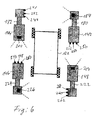
- FIG. 6 is another embodiment of the example of FIG. 5, wherein instead of two LED elements, three LED elements per reference camera are provided. This can ever account for one reference camera per measuring head.
- the reference camera 184 on the boom 180 are three LED elements 240, 242, 244 on the boom 182 of the measuring head 144th across from.
- the reference camera 200 on the measuring head 144 are opposite to three LED elements 246, 248, 250 on the measuring head 246.
- the reference camera 204 on the measuring head 148 are opposed by three LED elements 252, 254, 256.
- the reference camera 226 on the boom 224 are opposed by three LED elements 258, 260, 262 on the boom 222.
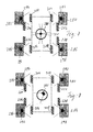
- FIG. 7 shows a wheel alignment device with an optical reference unit 270, which is arranged between reference targets 272, 274, 276, 280 approximately in the center of the measuring device.
- the reference targets are arranged on the inside of the measuring heads 280, 282, 284, 286.
- the reference unit 270 comprises either four stationary cameras or a camera with additional mirror optics to detect all reference targets on the measuring heads without rotation of the reference unit for calibration.
- FIG. 8 shows a modified embodiment of the device according to FIG. 7, wherein the reference unit 270 has a rotatably mounted camera 290, with which the reference targets 272, 274, 276, 278 can be observed.
- measuring cameras 292, 294, 296, 298 are provided which respectively detect measuring targets 302, 304, 306, 308 which are arranged on the wheels of a motor vehicle 310.
Abstract
Description
Die Erfindung betrifft eine Fahrwerkvermessungseinrichtung mit Meßköpfen zur Bestimmung der Radstellungen der Räder eines Kraftfahrzeuges auf einem Meßplatz, wobei jeder Meßkopf wenigstens eine Kamera aufweist, die auf ein im Blickfeld der Kamera angeordnetes, in einer festen Beziehung zu dem Rad des Kraftfahrzeuges positioniertes Meßtarget ausgerichtet ist, und wobei die Bilder der Kamera von einer Auswertungseinheit ausgewertet werden, um die räumliche Lage des Meßtargets und damit des Rades bezüglich der Position der Kamera bzw. des Meßkopfes zu bestimmen.The invention relates to a wheel alignment device with measuring heads for determining the wheel positions of the wheels of a motor vehicle on a measuring station, wherein each measuring head has at least one camera which is aligned with a positioned in the field of view of the camera, in a fixed relationship to the wheel of the motor vehicle measuring target, and wherein the images of the camera are evaluated by an evaluation unit in order to determine the spatial position of the measuring target and thus of the wheel with respect to the position of the camera or of the measuring head.
Derartige sogenannte berührungslose Fahrwerk- oder Achsvermessungseinrichtungen sind beispielsweise aus EP 0 895 056, EP 0 943 890 und DE 197 57 763 A1 bekannt. Bei diesen Fahrwerkvermessungseinrichtungen müssen die Meßköpfe, die zur Bestimmung der Radstellungen der Räder des Kraftfahrzeuges auf dem Meßplatz dienen, vor der eigentlichen Messung in Bezug zueinander ausgerichtet werden, was in der Praxis ein Problem darstellt.Such so-called non-contact chassis or wheel alignment devices are known, for example, from EP 0 895 056, EP 0 943 890 and DE 197 57 763 A1. In these wheel alignment devices, the measuring heads, which are used to determine the wheel positions of the wheels of the motor vehicle on the measuring station, must be aligned with respect to each other before the actual measurement, which is a problem in practice.
Bei der aus der EP 0 895 056 bekannten Fahrwerkmeßeinrichtung erfolgt die Ausrichtung der Meßköpfe untereinander dadurch, daß die Meßköpfe auf einem gemeinsamen Gestell an dem Meßplatz angeordnet sind, so daß die relative Lage der Meßköpfe untereinander bekannt ist. Allerdings sind die Meßköpfe verstellbar geführt, so dass an der Führung bereits Genauigkeitsprobleme auftreten. Eine derartige Anordnung hat noch den Nachteil, daß der Weg von den Meßköpfen zu den Meßtargets verhältnismäßig weit ist, so daß die Auflösung der Kameras ein Problem darstellt.In the known from EP 0 895 056 Fahrwerkmeßeinrichtung the alignment of the measuring heads with each other takes place in that the measuring heads are arranged on a common frame at the measuring station, so that the relative position of the measuring heads with each other is known. However, the measuring heads are guided adjustable, so that already occur on the leadership accuracy problems. Such an arrangement still has the disadvantage that the distance from the measuring heads to the measuring targets is relatively wide, so that the resolution of the cameras is a problem.
Bei der aus der EP 0 943 890 bekannten Fahrwerkmeßeinrichtung erfolgt die Ausrichtung der Meßköpfe untereinander dadurch, daß Bezugstargets an dem Meßplatz vorhanden sind mit deren Hilfe die Meßköpfe auszurichten sind. Da die Bezugstargest am Meßplatz vor dem Fahrzeug angeordnet sind, ist der Weg von den Bezugstargets zu den Meßköpfen bei den Hinterrädern sehr weit, so dass es schwierig ist, die erforderliche Genauigkeit bei der Kalibrierung die Meßköpfe zu erreichen.In the chassis measuring device known from EP 0 943 890, the alignment of the measuring heads takes place with one another in that reference targets are present on the measuring station with the aid of which the measuring heads are to be aligned. Since the reference star marks are placed in front of the vehicle at the measuring station, the distance from the reference targets to the measuring heads at the rear wheels is very wide, so that it is difficult to achieve the required accuracy in the calibration, the measuring heads.
Bei der aus der DE 197 57 763 A1 bekannten Fahrwerkmeßeinrichtung erfolgt die Ausrichtung der Meßköpfe untereinander dadurch, daß ein separater Rahmen mit Referenztargets zwischen den Meßköpfen und dem Fahrzeug angeordnet wird, wobei die Kalibrierung der Meßköpfe mit Hilfe der Bezugstargets erfolgt. Hier stört der Rahmen mit den Referenztargets bei dem Aufbau der Fahrwerkmeßeinrichtung und bei der Messung.In the known from DE 197 57 763 A1 Fahrwerkmeßeinrichtung the alignment of the measuring heads takes place with each other in that a separate frame with reference targets between the measuring heads and the vehicle is arranged, the calibration the measuring heads using the Bezugstargets done. Here the frame interferes with the reference targets in the construction of the chassis measuring device and in the measurement.
Es wurde auch bereits versucht, die Meßkameras selbst für die Kalibrierung der Meßköpfe zu benutzen und Referenztargets auf den quer zur Fahrrichtung des Kraftfahrzeuges gegenüberliegenden Meßköpfen anzubringen. Dabei ergibt sich das Problem, daß die Kamera, die sowohl zur Vermessung des ihr gegenüberliegenden Rades als auch zur Kalibrierung der relativen Lage der beiden gegenüberliegenden Meßköpfe dient, wegen der Brennweitenänderung bei jedem Meßgang zweimal kalibriert werden muß. Wenn eine derartige Kamera auch dazu verwendet wird, den Bezug auf den diagonal gegenüberliegenden Meßkopf herzustellen, sind drei Kalibrierungen der Kamera erforderlich, und derartige Kalibrierungen sind aufwendig.It has also been attempted to use the measuring cameras themselves for the calibration of the measuring heads and to attach reference targets on the transversely opposite to the direction of travel of the motor vehicle measuring heads. This results in the problem that the camera, which is used both for measuring the wheel opposite her as well as for calibrating the relative position of the two opposite measuring heads, must be calibrated twice because of the focal length change at each Meßgang. If such a camera is also used to make reference to the diagonally opposite measuring head, three calibrations of the camera are required, and such calibrations are expensive.
Demgegenüber liegt der Erfindung die Aufgabe zugrunde, eine Fahrwerk- oder Achsvermessungseinrichtung bereitzustellen, die ohne ortsfestes Bezugssystem auskommt und bei der die Kalibrierung mit möglichst wenig Kalibrierungsarbeiten und Bauteilen ermöglicht wird.In contrast, the present invention seeks to provide a suspension or Achsvermessungseinrichtung, which does not require stationary reference system and in which the calibration with as little calibration work and components is possible.
Dazu ist die erfindungsgemäße Fahrwerkvermssungseinrichtung gekennzeichnet durch ein optisches, in den Meßköpfen integriertes Referenzsystem zur Kalibrierung der Meßköpfe der Fahrwerkvermessungseinrichtung bezüglich der Position der Meßköpfe zueinander. Durch ein derartiges Referenzsystem wird es in vorteilhafter Weise möglich, mobile Meßköpfe zu verwenden, die vor der eigentlichen Messung bezüglich der Positionen zueienander kalibriert werden.For this purpose, the Fahrwerkvermssungseinrichtung invention is characterized by an optical, integrated in the measuring heads reference system for calibrating the measuring heads of the wheel alignment with respect to the position of the measuring heads to each other. By means of such a reference system, it is advantageously possible to use mobile measuring heads, which are calibrated relative to one another with respect to the positions before the actual measurement.
Eine vorteilhafte Ausgestaltung der erfindungsgemäßen Fahrwerkvermessungseinrichtung ist dadurch gekennzeichnet, daß das Referenzsystem eine Referenzkamera auf einem der Meßköpfe auf einer Seite des Kraftfahrzeuges und ein Referenztarget auf den auf derselben Fahrzeugseite gegenüberliegenden Meßkopf sowie Referenztargets auf der Innenseite eines vorderen und eines hinteren Meßkopfes umfaßt, die im Blickfeld der Meßkameras auf den gegenüberliegenden Meßköpfen liegen. Diese Anordnung hat den Vorteil, daß die Meßköpfe je nach Radstand und Spurweite frei positionierbar sind, wobei die Meßkameras bei der Messung die Meßtargets im Blickfeld und die Meß- und Referenzkameras die Meß- bzw. Referenztargets im Blickfeld haben, wenn kein Fahrzeug in dem Meßplatz vorhanden ist. Gegenüber dem System bestehend aus den Meßkameras und Meßtargets sind nur zwei zusätzliche Kameras und vier zusätzliche Targets erforderlich. Die Meßköpfe sind diagonal tauschbar, und es kann eine Selbstkontrolle durch Rundummessung durchgeführt werden. Zur Kalibrierung muß das Fahrzeug aus dem Meßfeld herausgefahren werden.An advantageous embodiment of the wheel alignment measuring device according to the invention is characterized in that the reference system includes a reference camera on one of the measuring heads on one side of the motor vehicle and a reference target on the opposite side of the same vehicle head and reference targets on the inside of a front and a rear measuring head in the field of view the measuring cameras lie on the opposite measuring heads. This arrangement has the advantage that the measuring heads are freely positionable depending on the wheelbase and track, the measuring cameras in the measurement, the measuring targets in the field of view and the measuring and reference cameras the measuring or reference targets in the field of vision, if no vehicle in the tester is available. Compared to the system consisting of the measuring cameras and measuring targets only two additional cameras and four additional targets are required. The measuring heads are diagonally exchangeable, and self-checking can be done by rounding. For calibration, the vehicle must be moved out of the measuring field.
Eine vorteilhafte Ausgestaltung der erfindungsgemäßen Fahrwerkvermessungseinrichtung ist dadurch gekennzeichnet, daß das Referenzsystem eine Referenzkamera an einem der vorderen Meßköpfe und ein Referenztarget an dem gegenüberliegenden Meßkopf aufweist, wobei Kamera und Referenztarget vor oder hinter dem Kraftfahrzeug liegen, und daß das Referenzsystem ferner eine Referenzkamera in einem der seitlichen Meßköpfe und ein Referenztarget auf dem auf derselben Fahrzeugseite gegenüberliegenden Meßkopf aufweist. Hier ergibt sich der Vorteil, daß die Meßköpfe je nach Radstand und Spurweite frei positionierbar sind, solange sie sich gegenseitig im Blickfeld haben. Es sind nur drei Referenzkameras und Targets notwendig, um das Referenzsystem aufzubauen.An advantageous embodiment of the chassis measuring device according to the invention is characterized in that the reference system has a reference camera on one of the front measuring heads and a reference target on the opposite measuring head, with camera and reference target in front or behind the motor vehicle, and that the reference system further comprises a reference camera in one of having lateral measuring heads and a reference target on the opposite side of the same vehicle side measuring head. Here there is the advantage that the measuring heads are freely positionable depending on the wheelbase and track, as long as they have each other in view. Only three reference cameras and targets are needed to build the reference system.
Eine vorteilhafte Ausgestaltung der erfindungsgemäßen Fahrwerkvermessungseinrichtung ist dadurch gekennzeichnet, daß ferner an den hinteren Meßköpfen eine Referenzkamera an einem Meßkopf und ein Referenztarget an dem gegenüberliegenden Meßkopf angeordnet ist. Dabei ist vorteilhaft, daß die Meßköpfe je nach Radstand und Spurweite frei positionierbar sind, solange sie sich gegenseitig im Blickfeld haben. Die Meßköpfe sind diagonal tauschbar, und es ist eine Selbstkontrolle der Fahrwerkmeßeinrichtung durch Rundummessung des Bezugssystems möglich, wie es bei den sogenannten Achtgeber-Achsmeßgeräten der Fall ist.An advantageous embodiment of the wheel alignment measuring device according to the invention is characterized in that further arranged on the rear measuring heads a reference camera on a measuring head and a reference target on the opposite measuring head. It is advantageous that the measuring heads are freely positionable depending on the wheelbase and track, as long as they have each other in the field of view. The measuring heads are diagonally interchangeable, and it is a self-control of Fahrwerkmeßeinrichtung by Rundummessung of the reference system possible, as is the case with the so-called Achtgeber Achsmeßgeräten.
Eine vorteilhafte Ausgestaltung der erfindungsgemäßen Fahrwerkvermessungseinrichtung ist gekennzeichnet durch ein optisches Strahlteiler- oder Spiegelsystem, das zwischen je einem Referenztarget und je einer Meßkamera derart angeordnet ist, dass die Referenztargts von der Meßkamera beobachtet werden. Da durch diese Anordnung Referenzkameras durch ein optisches Strahlteiler- oder Spiegelsystem ersetzt werden, hat diese Anordnung hat den Vorteil, daß durch das Strahlteiler- oder Spiegelsystem jeweils eine Referenzkamera eingespart wird, was die gesamte Einrichtung kostengünstiger macht.An advantageous embodiment of the chassis measuring device according to the invention is characterized by an optical beam splitter or mirror system, which is arranged between each reference target and a respective measuring camera such that the Referenztargts be observed by the measuring camera. Since reference cameras are replaced by an optical beam splitter or mirror system by this arrangement, this arrangement has the advantage that a reference camera is saved by the beam splitter or mirror system, which makes the entire device cheaper.
Eine vorteilhafte Ausgestaltung der erfindungsgemäßen Fahrwerkvermessungseinrichtung ist dadurch gekennzeichnet, daß das Referenzsystem an den seitlichen Meßköpfen je eine CCD-Referenzkamera, die auf dem gegenüberliegenden Meßkopf auf der gleichen Seite gerichtet ist, und an dem gegenüberliegenden Meßkopf je mindestens zwei LED-Elemente als Referenztargets angeordnet sind, und daß an den vorderen und/oder hinteren Meßköpfen jeweils zusätzliche CCD-Referenzkameras und an dem gegenüberliegenden Meßköpfen LED-Elemente als Referenztargets angeordnet sind. Bei dieser Anordnung sind nur einfache Zeilenkameras und LED-Elemente notwendig, während die Meßköpfe frei positionierbar und diagonal tauschbar sind.An advantageous embodiment of the wheel alignment measuring device according to the invention is characterized in that the reference system at the lateral measuring heads per a CCD reference camera, which is directed to the opposite measuring head on the same side, and arranged at the opposite measuring head per at least two LED elements as reference targets , And that at the front and / or rear measuring heads each additional CCD reference cameras and at the opposite measuring heads LED elements are arranged as reference targets. In this arrangement, only simple line scan cameras and LED elements are necessary, while the measuring heads are freely positionable and diagonally exchangeable.
Eine vorteilhafte Ausgestaltung der erfindungsgemäßen Fahrwerkvermessungseinrichtung ist dadurch gekennzeichnet, daß drei LED-Elemente als Referenztarget vorgesehen sind. Hier ist jeweils nur eine CCD-Referenzkamera pro Meßkopf notwendig, was wiederum zur Kostenersparnis führt.An advantageous embodiment of the chassis measuring device according to the invention is characterized in that three LED elements are provided as a reference target. Here, only one CCD reference camera per measuring head is necessary, which in turn leads to cost savings.
Eine vorteilhafte Ausgestaltung der erfindungsgemäßen Fahrwerkvermessungseinrichtung ist dadurch gekennzeichnet, daß das Referenzsystem Referenztargets an der Innenseite der Meßköpfe und eine optische Referenzeinheit zwischen den Referenztargets aufweist, die auf die Referenztargets ausgerichtet ist. Durch diese Anordnung wird eine zentrale Referenzeinheit zur Kalibrierung der Fahrwerkvermessungseinrichtung geschaffen, die nach ihrer Einrichtung und Kalibrierung jederzeit zur Verfügung steht. Die eigentlichen Meßköpfe zur Vermessung der Radstellungen können dabei verhältnismäßig einfach ausgeführt werden. Optisch können die Tiefenschärfebereiche von Meßsystem und Referenzsystem getrennt festgelegt und kalibriert werden, so daß eine Nachkalibrierung relativ selten erforderlich ist. Die Meßköpfe sind bei dieser Anordnung wiederum diagonal tauschbar.An advantageous embodiment of the chassis measuring device according to the invention is characterized in that the reference system has reference targets on the inside of the measuring heads and an optical reference unit between the reference targets, which is aligned with the reference targets. By this arrangement, a central reference unit for calibration of the wheel alignment device is provided, which is available at any time after their installation and calibration. The actual measuring heads for measuring the wheel positions can be carried out relatively easily. Optically, the depth of field of the measuring system and reference system can be set and calibrated separately, so that a recalibration is relatively rarely required. The measuring heads are again diagonally exchangeable in this arrangement.
Eine vorteilhafte Ausgestaltung der erfindungsgemäßen Fahrwerkvermessungseinrichtung ist dadurch gekennzeichnet, daß die Referenzoptik vier jeweils auf die Referenztargets gerichtete Kameras umfaßt. Diese Anordnung hat den Vorteil, daß nur eine einmalige Justierung des Referenzsystems notwendig ist, und daß keine bewegten Teile in der Referenzeinheit vorhanden sind.An advantageous embodiment of the chassis measuring device according to the invention is characterized in that the reference optics comprises four each directed to the reference targets cameras. This arrangement has the advantage that only a single adjustment of the reference system is necessary, and that no moving parts are present in the reference unit.
Eine vorteilhafte Ausgestaltung der erfindungsgemäßen Fahrwerkvermessungseinrichtung ist dadurch gekennzeichnet, daß die Referenzoptik eine Referenzkamera und ein Spiegel- oder Strahlteilersystem umfaßt, das das Blickfeld der Referenzkamera auf die Referenztargets richtet. Dadurch können gegenüber dem vorhergehenden Ausführungsbeispiel drei Kameras eingespart werden.An advantageous embodiment of the chassis measuring device according to the invention is characterized in that the reference optics comprises a reference camera and a mirror or beam splitter system which directs the field of view of the reference camera to the reference targets. As a result, compared to the previous embodiment, three cameras can be saved.
Eine vorteilhafte Ausgestaltung der erfindungsgemäßen Fahrwerkvermessungseinrichtung ist dadurch gekennzeichnet, daß die Referenzoptik eine drehbar gelagerte Referenzkamera umfaßt. Dafür können die eigentlichen Meßköpfe zur Vermessung der Räder verhältnismäßig einfach ausgeführt werden, und die Tiefenschärfenbereiche von Meßsystem und Referenzsystem können getrennt festgelegt und kalibriert werden. Da nur eine Kamera für die Referenzeinheit erforderlich ist, wird gegen dem vorhergehenden Ausführungsbeispiel eine Kostenersparnis erzielt.An advantageous embodiment of the wheel alignment measuring device according to the invention is characterized in that the reference optics comprises a rotatably mounted reference camera. For this, the actual measuring heads for measuring the wheels can be made relatively simple, and the depth of field of the measuring system and reference system can be set separately and calibrated. Since only one camera for the Reference unit is required, a cost savings is achieved against the previous embodiment.
Ausführungsbeispiele der Erfindung werden nun anhand der beiliegenden Zeichnungen beschrieben. Es zeigen:
- Fig. 1 eine schematische Darstellung einer Fahrwerkvermessungseinrichtung mit Referenztargets an den Meßköpfen und Referenzkameras an den Meßköpfen;
- Fig. 2 eine schematische Darstellung einer Fahrwerkvermessungseinrichtung mit einer Referenzkamera und einem Referenztarget auf Auslegern der vorderen Meßköpfe;
- Fig. 3 eine schematische Darstellung einer Fahrwerkvermessungseinrichtung mit einer Referenzkamera und einem gegenüberliegenden Referenztarget auf Auslegern an den vorderen Meßköpfen und eine ebensolche Anordnung auf den hinteren Meßköpfen;
- Fig. 4 ein Spiegelsystem in den vorderen Meßköpfen;
- Fig. 5 eine schematische Darstellung einer Fahrwerkvermessungseinrichtung mit einer Referenzeinheit aus CCD-Kameras und LED-Elementen;
- Fig. 6 eine schematische Darstellung einer Fahrwerkvermessungseinrichtung mit CCD-Referenzkameras und je drei LED-Elementen als Referenztarget;
- Fig. 7 eine schematische Darstellung einer Fahrwerkvermessungseinrichtung mit einer zusätzlichen Referenzeinheit zentral zwischen den Meßköpfen; und
- Fig. 8 eine schematische Darstellung einer Fahrwerkvermessungseinrichtung mit einer anderen Ausführungsform einer zentralen Referenzeinheit.
- 1 shows a schematic representation of a wheel alignment device with reference targets on the measuring heads and reference cameras on the measuring heads;
- 2 shows a schematic illustration of a wheel alignment device with a reference camera and a reference target on arms of the front measuring heads;
- 3 is a schematic representation of a wheel alignment device with a reference camera and an opposing reference target on cantilevers on the front measuring heads and a similar arrangement on the rear measuring heads.
- 4 shows a mirror system in the front measuring heads;
- 5 shows a schematic representation of a wheel alignment device with a reference unit comprising CCD cameras and LED elements;
- 6 shows a schematic illustration of a wheel alignment device with CCD reference cameras and three LED elements each as a reference target;
- 7 is a schematic representation of a wheel alignment device with an additional reference unit centrally between the measuring heads; and
- Fig. 8 is a schematic representation of a wheel alignment device with another embodiment of a central reference unit.
Fig. 1 zeigt eine Fahrwerkvermessungseinrichtung mit einem in den Meßköpfen integrierten Referenzsystem. An einem schematisch dargestellten Kraftfahrzeug 32 sind Meßtargets 34, 36, 38, 40 an den jeweiligen Rädern angeordnet. Die Meßtargets werden von Meßkameras 42, 44, 46 bzw. 48 beobachtet, wenn die Fahrwerkvermessung durchgeführt wird. Die Meßkameras 42, 44, 46, 48 liegen in Meßköpfen 52, 54, 56, 58.Fig. 1 shows a wheel alignment device with a built-in measuring heads reference system. On a
Die Frontseite der Fahrzeuges 32 ist, wie die Frontseite der Fahrzeuge bei den folgenden Ausführungsbeispielen, in den Zeichnungen nach oben gerichtet, sodass die oberen Meßköpfe als vordere Meßköpfe oder Meßköpfe an den Vorderrädern und die unteren Meßköpfe als hintere Meßköpfe oder Meßköpfe an den Hinterrädern bezeichnet werden.The front of the
An den Meßköpfen 52 und 56 sind Referenztargets 60, 61 angeordnet, die jeweils im Blickwinkel der Meßkamera 44 bzw. 48 liegen, wenn kein Fahrzeug im Meßplatz vorhanden ist. Das Referenzsystem wird vervollständigt durch Referenzkameras 62, 64 in den Meßköpfen 54, 56 und Referenztargets 66, 68 an den Meßköpfen 58, 54. Die Targets 66, 68 liegen im Blickwinkel der Referenzkameras 64 bzw. 62.At the measuring heads 52 and 56
Bei dieser Anordnung wird eine Selbstkalibrierung der Meßköpfe vor der Fahrwerkvermessung durchgeführt. Durch eine Kombination der Meßköpfe mit den Meßtargets und der Referenzköpfe mit den Referenztargets kann die Position und Winkelstellung der einzelnen Meßköpfe zueinander bestimmt werden, solange sich kein Kraftfahrzeug auf dem Meßplatz befindet. Nach der Kalibrierung wird das Fahrzeug dann in den Meßplatz eingefahren und vermessen.In this arrangement, a self-calibration of the measuring heads is carried out before the wheel alignment. By combining the measuring heads with the measuring targets and the reference heads with the reference targets, the position and angular position of the individual measuring heads can be determined relative to each other as long as no motor vehicle is on the measuring station. After calibration, the vehicle is then retracted and measured in the measuring station.
Fig. 2 zeigt eine Fahrwerkvermessungseinrichtung mit zusätzlichen optischen Einrichtung an den Meßköpfen. Ein Fahrzeug 122 umfaßt Meßtargets 124, 126, 128, 130 an seinen Rädern, wobei die Meßtargets im Blickwinkel von Meßkameras 132, 134, 136 bzw. 138 liegen. Die Meßkameras sind in Meßköpfen 142, 144, 146, 148 angeordnet. In den vorderen Meßköpfen 142, 144 sind Referenzkameras 150, 152 angeordnet, die Referenztargets 154, 156 im Blickfeld haben, die an den hinteren Meßköpfen 148 bzw. 146 angeordnet sind. Über Ausleger 158, 160 sind an den vorderen Meßköpfen 144 bzw. 142 eine Referenzkamera 162 bzw. ein Referenztarget 164 angeordnet. Bei dieser Anordnung stellen die Referenzkameras 150, 152 über die Referenztargets 154, 156 den Bezug zwischen den vorderen Meßköpfen 142, 144 und den hinteren Meßköpfen 146, 148 her, während die Referenzkamera 162 und das Referenztarget 164 den Bezug quer zur Fahrtrichtung des Fahrzeugs zwischen den seitlichen Meßköpfen herstellt. Bei dieser Anordnung erfolgt die Selbstkalibrierung der Meßköpfe während einer Fahrwerkvermessung.Fig. 2 shows a wheel alignment device with additional optical device to the measuring heads. A
Fig. 3 zeigt eine weitere Ausgestaltung des Ausführungsbeispiels von Fig. 2. Die Fahrwerkvermessungseinrichtung nach Fig. 3 hat zwei zusätzliche Ausleger 166, 168 an den hinteren Meßköpfen 148 bzw. 146, auf denen eine Referenzkamera 170 und ein Referenztarget 172 angeordnet sind. Mit dieser Anordnung ist eine sogenannte Rundummessung möglich, so daß die Justage der Fahrwerkvermessungseinrichtung einer Selbstkontrolle unterworfen werden kann.FIG. 3 shows a further embodiment of the embodiment of FIG. 2. The wheel alignment device according to FIG. 3 has two
Fig. 4 zeigt ein Spiegelsystem, durch das pro Meßkopf der in Fig. 3 gezeigten Art eine Kamera eingespart bzw. durch das Spiegelsystem ersetzt wird. So wird bei dem Meßkopf 144 die Kamera 162 von Fig. 3 eingespart, während in dem Meßkopf 142 die Kamera 150 von Fig. 3 einspart wird. Dazu ist in dem Meßkopf 144 an dem Ausleger 158 ein Spiegelsystem 174 angeordnet, und in dem Meßkopf 144 selbst ist ein Kippspiegelsystem 176 vorgesehen, das den Strahlengang der Meßkamera 134 von einem Strahlengang zu dem Spiegelsystem 174 zu einem Strahlengang zu dem gegenüberliegenden Meßtarget umschaltet. In dem Meßkopf 142 ist ein Kippspiegelsystem 178 vorgesehen, das den Strahlengang der Meßkamera 132 zwischen einem Strahlengang zu dem Meßtarget und einem Strahlengang zu dem Referenztarget umschaltet.FIG. 4 shows a mirror system by which a camera is saved or replaced by the mirror system per measuring head of the type shown in FIG. Thus, in the measuring
Die Anordnung der Fahrwerkvermessungseinrichtung nach Fig. 5 entspricht der von Fig. 3, wobei in Fig. 5 zur Vereinfachung die Meßkameras zur Vermessungen der einzelnen Räder nicht dargestellt sind. Gemäß Fig. 5 haben die vorderen Meßköpfe 142, 144 Ausleger 180, 182, an denen jeweils eine Referenzkamera 184, 186, bestehend aus CCD-Zeilen, und je zwei LED-Elemente 188, 190 bzw. 192, 194. Die LED Elemente 188, 190 bfw. 192,194 sind jeweils im Blickfeld der Referenzkameras 186 bzw. 184 angeordnet. Mit einer derartigen Anordnung läßt sich in bekannter Weise die Winkelstellung der Meßköpfe 142, 144 quer zur Fahrtrichtung des Fahrzeuges bestimmen. Eine entsprechende Anordnung ist zwischen den seitlich am Fahrzeug einander gegenüberliegenden Meßköpfen 142, 146 bzw. 144, 146 vorgesehen. Danach sind in den Meßköpfen 142, 144, 146, 148 jeweils Referenzkameras (CCD-Zeilen) 198, 200, 202, 204 und LED-Elemente 206, 208; 210, 212; 214, 216; 218, 220 angeordnet, die jeweils im Blickfeld der gegenüberliegenden Referenzkamera liegen.The arrangement of the wheel alignment device according to FIG. 5 corresponds to that of FIG. 3, wherein the measuring cameras for measuring the individual wheels are not shown in FIG. 5 for the sake of simplicity. 5, the front measuring heads 142, 144
Bei der Anordnung der Fahrwerkvermessungseinrichtung nach Fig. 5 ist eine entsprechende Anordnung zu der Anordnung auf der Vorderseite auch auf Auslegern 222, 224 an den hinteren Meßköpfen 146, 148 vorgesehen. An dem Meßkopf 146 ist eine Referenzkamera (CCD-Zeile) 226 und an dem Meßkopf 148 eine Referenzkamera 228 vorgesehen. Im Blickfeld der Referenzkamera 126 liegen zwei LED-Elemente 230, 232, und im Blickfeld der Referenzkamera 228 liegen zwei LED-Elemente 234, 236. Dadurch, daß jeweils zwei LED-Elemente einer Referenzkamera gegenüberliegen, kann der Abstand zwischen den Meßköpfen zueinander bestimmt werden. Die Lage jedes Meßkopfes zur Senkrechten kann durch ein Pendelsystem ermittelt werden. Bei dieser Anordnung ist vorteilhaft, daß einfache Zeilenkameras für die Referenzkameras und LED-Elemente verwendet werden können. Ferner können die Meßköpfe frei positioniert und diagonal ausgetauscht werden.In the arrangement of the wheel alignment device according to FIG. 5, a corresponding arrangement to the arrangement on the front side is also provided on
Fig. 6 ist eine weitere Ausführungsform des Beispiels von Fig. 5, wobei statt zwei LED-Elementen drei LED-Elemente pro Referenzkamera vorgesehen sind. Dadurch kann je eine Referenzkamera pro Meßkopf entfallen. So liegen der Referenzkamera 184 auf dem Ausleger 180 drei LED-Elemente 240, 242, 244 an dem Ausleger 182 des Meßkopfes 144 gegenüber. Der Referenzkamera 200 an dem Meßkopf 144 liegen drei LED-Elemente 246, 248, 250 auf dem Meßkopf 246 gegenüber. Der Referenzkamera 204 an dem Meßkopf 148 liegen drei LED-Elemente 252, 254, 256 gegenüber. Schließlich liegen der Referenzkamera 226 an dem Ausleger 224 drei LED-Elemente 258, 260, 262 auf dem Ausleger 222 gegenüber.FIG. 6 is another embodiment of the example of FIG. 5, wherein instead of two LED elements, three LED elements per reference camera are provided. This can ever account for one reference camera per measuring head. Thus, the
Fig. 7 zeigt eine Fahrwerkvermessungseinrichtung mit einer optischen Referenzeinheit 270, die zwischen Referenztargets 272, 274, 276, 280 in etwa in der Mitte der Vermessungseinrichtung angeordnet ist. Die Referenztargets sind an der Innenseite der Meßköpfe 280, 282, 284, 286 angeordnet. Die Referenzeinheit 270 umfaßt entweder vier ortfest angeordnete Kameras oder eine Kamera mit zusätzlicher Spiegeloptik, um alle Referenztargets an den Meßköpfen ohne Drehung der Referenzeinheit zur Kalibrierung erfassen zu können.FIG. 7 shows a wheel alignment device with an
Fig. 8 zeigt eine abgewandelte Ausführungsform der Einrichtung nach Fig. 7, wobei die Referenzeinheit 270 eine drehbar gelagerte Kamera 290 aufweist, mit der die Referenztargets 272, 274, 276, 278 beobachtet werden können.FIG. 8 shows a modified embodiment of the device according to FIG. 7, wherein the
Im übrigen sind in den beiden Ausführungsbeispielen der Figuren 7 und 8 Meßkameras 292, 294, 296, 298 vorgesehen, die jeweils Meßtargets 302, 304, 306, 308, die an den Rädern eines Kraftfahrzeuges 310 angeordnet sind, erfassen.Incidentally, in the two exemplary embodiments of FIGS. 7 and 8, measuring
Claims (11)
Applications Claiming Priority (2)
| Application Number | Priority Date | Filing Date | Title |
|---|---|---|---|
| DE10043354A DE10043354A1 (en) | 2000-09-02 | 2000-09-02 | Chassis measuring device |
| EP01120596A EP1184640B1 (en) | 2000-09-02 | 2001-08-29 | Arrangement for vehicle geometry measurement |
Related Parent Applications (1)
| Application Number | Title | Priority Date | Filing Date |
|---|---|---|---|
| EP01120596A Division EP1184640B1 (en) | 2000-09-02 | 2001-08-29 | Arrangement for vehicle geometry measurement |
Publications (2)
| Publication Number | Publication Date |
|---|---|
| EP1669715A1 true EP1669715A1 (en) | 2006-06-14 |
| EP1669715B1 EP1669715B1 (en) | 2008-08-13 |
Family
ID=7654808
Family Applications (2)
| Application Number | Title | Priority Date | Filing Date |
|---|---|---|---|
| EP06111762A Expired - Lifetime EP1669715B1 (en) | 2000-09-02 | 2001-08-29 | Chassis measurement device |
| EP01120596A Expired - Lifetime EP1184640B1 (en) | 2000-09-02 | 2001-08-29 | Arrangement for vehicle geometry measurement |
Family Applications After (1)
| Application Number | Title | Priority Date | Filing Date |
|---|---|---|---|
| EP01120596A Expired - Lifetime EP1184640B1 (en) | 2000-09-02 | 2001-08-29 | Arrangement for vehicle geometry measurement |
Country Status (3)
| Country | Link |
|---|---|
| US (1) | US6690456B2 (en) |
| EP (2) | EP1669715B1 (en) |
| DE (3) | DE10043354A1 (en) |
Cited By (1)
| Publication number | Priority date | Publication date | Assignee | Title |
|---|---|---|---|---|
| US7774946B2 (en) | 2006-08-04 | 2010-08-17 | Fasep 2000 S.R.L. | Method and device for non-contact measurement of the alignment of motor vehicle wheels |
Families Citing this family (62)
| Publication number | Priority date | Publication date | Assignee | Title |
|---|---|---|---|---|
| BE1013152A3 (en) * | 1999-11-24 | 2001-10-02 | Krypton Electronic Eng Nv | Method for determining the dynamic behaviour of a vehicle on a test bench. |
| WO2001071280A2 (en) | 2000-03-23 | 2001-09-27 | Snap-On Technologies, Inc. | Self-calibrating, multi-camera machine vision measuring system |
| US6968282B1 (en) | 2000-05-22 | 2005-11-22 | Snap-On Incorporated | Self-calibrating, multi-camera machine vision measuring system |
| WO2002103286A1 (en) | 2001-06-15 | 2002-12-27 | Snap-On Technologies, Inc. | Self-calibrating position determination system |
| US7062861B2 (en) * | 2001-06-28 | 2006-06-20 | Snap-On Incorporated | Self-calibrating position determination system and user interface |
| ES2335196T3 (en) * | 2002-02-04 | 2010-03-23 | Corghi S.P.A. | DEVICE FOR MEASURING THE CHARACTERISTIC POSITION PARAMETERS OF A VEHICLE. |
| US7336350B2 (en) * | 2002-05-15 | 2008-02-26 | Hunter Engineering Company | Wheel alignment apparatus and method utilizing three-dimensional imaging |
| US6871409B2 (en) | 2002-12-18 | 2005-03-29 | Snap-On Incorporated | Gradient calculating camera board |
| US8306696B2 (en) * | 2003-04-17 | 2012-11-06 | Driveright Holdings, Ltd. | Method and system for aligning a vehicle with an artificial horizon |
| US20050005461A1 (en) * | 2003-06-25 | 2005-01-13 | Henry Rohrig | Truck alignment system |
| US7164472B2 (en) | 2003-10-09 | 2007-01-16 | Hunter Engineering Company | Common reference target machine vision wheel alignment system |
| DE102004013441A1 (en) | 2004-03-18 | 2005-10-13 | Beissbarth Gmbh | Measuring method and measuring device for determining the spatial position of a wheel rim and wheel alignment device |
| US7525654B2 (en) * | 2004-10-20 | 2009-04-28 | Duquesne University Of The Holy Spirit | Tunable laser-based chemical imaging system |
| EP1831642A1 (en) * | 2004-12-30 | 2007-09-12 | Snap-on Incorporated | Non-contact vehicle measurement method and system |
| WO2006124642A1 (en) * | 2005-05-13 | 2006-11-23 | Snap-On Incorporated | Wheel aligner measurement module attachment system |
| US7583372B2 (en) * | 2005-06-01 | 2009-09-01 | Hunter Engineering Company | Machine vision vehicle wheel alignment image processing methods |
| US7454841B2 (en) * | 2005-11-01 | 2008-11-25 | Hunter Engineering Company | Method and apparatus for wheel alignment system target projection and illumination |
| DE102005060073B4 (en) * | 2005-12-15 | 2008-02-14 | Beissbarth Gmbh | Measuring or reference unit and chassis measuring system with it |
| DE102005063050A1 (en) * | 2005-12-29 | 2007-07-05 | Robert Bosch Gmbh | Wheel axial geometry e.g. wheel camber, contact less measurement method for use in e.g. motor vehicle, involves utilizing distance sensor of measurement system, where distance measurement sensor determines distance to three points at wheel |
| US7710555B2 (en) | 2006-06-27 | 2010-05-04 | Burke E. Porter Machinery Company | Apparatus and method for determining the orientation of an object such as vehicle wheel alignment |
| US7313869B1 (en) | 2006-07-18 | 2008-01-01 | Snap-On Incorporated | Vehicle wheel alignment system and methodology |
| DE102006041822A1 (en) * | 2006-09-06 | 2008-03-27 | Beissbarth Gmbh | Method for chassis measurement of a motor vehicle, chassis measuring device and motor vehicle inspection line |
| DE102006041821A1 (en) * | 2006-09-06 | 2008-03-27 | Beissbarth Gmbh | Method for the relative positioning of a measuring object and a motor vehicle to a measuring device and measuring device and chassis measuring device |
| US7864309B2 (en) * | 2007-05-04 | 2011-01-04 | Burke E. Porter Machinery Company | Non contact wheel alignment sensor and method |
| US7684026B2 (en) * | 2007-07-27 | 2010-03-23 | Snap-On Incorporated | Fault tolerant wheel alignment head and system |
| US7640673B2 (en) * | 2007-08-01 | 2010-01-05 | Snap-On Incorporated | Calibration and operation of wheel alignment systems |
| CN103453857B (en) * | 2007-08-31 | 2017-12-22 | 实耐宝公司 | Wheel alignment system and method |
| CN103226010B (en) * | 2007-08-31 | 2016-08-10 | 实耐宝公司 | Wheel alignment system and method |
| CN103217129A (en) * | 2007-08-31 | 2013-07-24 | 实耐宝公司 | Wheel alignment system and wheel alignment method |
| DE102007047424A1 (en) | 2007-10-04 | 2009-04-09 | Robert Bosch Gmbh | Automotive component surveying system, use and method |
| US20090128516A1 (en) * | 2007-11-07 | 2009-05-21 | N-Trig Ltd. | Multi-point detection on a single-point detection digitizer |
| DE102008006329A1 (en) | 2008-01-28 | 2009-07-30 | Robert Bosch Gmbh | Method and device for checking the referencing of measuring heads of a chassis measuring system |
| DE102008000833A1 (en) * | 2008-03-26 | 2009-10-01 | Robert Bosch Gmbh | Measuring head for a chassis measuring system, chassis measuring system and method for determining the position parameters of measuring heads of a chassis measuring system |
| DE102008001339A1 (en) | 2008-04-23 | 2009-10-29 | Robert Bosch Gmbh | Method and device for wheel alignment |
| FR2930986B1 (en) * | 2008-05-07 | 2010-06-11 | Actia Muller | METHOD AND DEVICE FOR CONTROLLING A TWO-WHEELED VEHICLE |
| DE102009028796A1 (en) | 2008-09-12 | 2010-04-15 | Robert Bosch Gmbh | Chassis measuring device with homing device |
| CN102150010A (en) * | 2008-09-12 | 2011-08-10 | 罗伯特·博世有限公司 | Target arrangement, unit of target arrangements and device for optically aligning an axle |
| DE102008042018A1 (en) * | 2008-09-12 | 2010-03-18 | Robert Bosch Gmbh | Method for adjusting or calibrating a vehicle surroundings sensor and vehicle surroundings sensor adjustment or calibration arrangement |
| DE102010040655A1 (en) | 2010-09-13 | 2012-03-15 | Robert Bosch Gmbh | Method and device for calibrating a reference system for vehicle measurement |
| DE102011086548A1 (en) | 2011-05-24 | 2012-11-29 | Robert Bosch Gmbh | Device and method for chassis measurement of a motor vehicle |
| ITMI20111695A1 (en) * | 2011-09-21 | 2013-03-22 | Cemb S P A | DEVICE AND MEASUREMENT PROCEDURE FOR DIMENSIONS AND CORNERS OF WHEELS, STEERING AND CHASSIS OF VEHICLES IN GENERAL. |
| DE102012206212A1 (en) | 2012-04-16 | 2013-10-17 | Robert Bosch Gmbh | Method for determining the orientation of at least one running rail of a measuring station and device for carrying out the method |
| WO2014033086A1 (en) * | 2012-08-29 | 2014-03-06 | Robert Bosch Gmbh | An apparatus for synchronization of cameras in a vehicle wheel alignment system and a method thereof |
| DE102013211207A1 (en) | 2013-06-14 | 2014-12-18 | Robert Bosch Gmbh | Device and method for homing transducers for vehicle measurement |
| DE102014204686A1 (en) * | 2014-03-13 | 2015-09-17 | Robert Bosch Gmbh | Method and device for image acquisition in vehicle surveying |
| US20180180411A1 (en) * | 2014-06-06 | 2018-06-28 | Cemb S.P.A. | Device and method for determining at least one parameter characteristic of at least one component of a vehicle in the scope of a diagnostic, maintenance or monitoring operation |
| DE102014219109A1 (en) | 2014-09-23 | 2016-03-24 | Robert Bosch Gmbh | Reference system and transducers for use in vehicle surveying |
| CN105136484A (en) * | 2015-06-02 | 2015-12-09 | 深圳科澳汽车科技有限公司 | Inter-shaft four-wheel positioning detection device and detection method |
| WO2018035040A1 (en) | 2016-08-16 | 2018-02-22 | Snap-On Incorporated | Vehicle wheel alignment methods and systems |
| US10551180B2 (en) | 2016-09-30 | 2020-02-04 | Burke E. Porter Marchinery Company | Wheel alignment measurement method and system for vehicle wheels |
| CN106813599B (en) * | 2017-03-23 | 2018-12-21 | 深圳市鹰眼在线电子科技有限公司 | Automobile camera shooting measures component and automobile three-dimensional four-wheel aligner method and system |
| US11835646B2 (en) | 2018-04-30 | 2023-12-05 | BPG Sales and Technology Investments, LLC | Target alignment for vehicle sensor calibration |
| US11243074B2 (en) | 2018-04-30 | 2022-02-08 | BPG Sales and Technology Investments, LLC | Vehicle alignment and sensor calibration system |
| US11624608B2 (en) | 2018-04-30 | 2023-04-11 | BPG Sales and Technology Investments, LLC | Vehicular alignment for sensor calibration |
| US11781860B2 (en) | 2018-04-30 | 2023-10-10 | BPG Sales and Technology Investments, LLC | Mobile vehicular alignment for sensor calibration |
| US11597091B2 (en) | 2018-04-30 | 2023-03-07 | BPG Sales and Technology Investments, LLC | Robotic target alignment for vehicle sensor calibration |
| CN108917690B (en) * | 2018-05-29 | 2020-08-28 | 深圳先进技术研究院 | Calculation method and measurement device for automobile king pin angle |
| JP7000254B2 (en) * | 2018-06-01 | 2022-01-19 | トヨタ自動車株式会社 | Wheel alignment adjustment system |
| CN112639403A (en) | 2018-09-13 | 2021-04-09 | 实耐宝公司 | Motor vehicle aligner with improved accuracy and non-stop positioning using drive direction calculation |
| CN109323871B (en) * | 2018-10-28 | 2020-08-07 | 吉林大学 | Calibrating device for slotted ball pin directional arc arm single four-wheel aligner |
| CN109883326A (en) * | 2019-03-29 | 2019-06-14 | 湖南省鹰眼在线电子科技有限公司 | A kind of videographic measurment formula automobile three-dimensional four-wheel aligner method, system and medium |
| CN111879261A (en) * | 2020-08-13 | 2020-11-03 | 深圳市道通科技股份有限公司 | Camera assembly, wheel positioning system and wheel positioning method |
Citations (2)
| Publication number | Priority date | Publication date | Assignee | Title |
|---|---|---|---|---|
| US4931964A (en) * | 1984-09-07 | 1990-06-05 | Fmc Corporation | Vehicle wheel alignment apparatus and method |
| EP1003011A1 (en) * | 1998-11-20 | 2000-05-24 | Compagnie Europeenne d'Equipements de Garage | Optical determination of the relative positions of objects in space |
Family Cites Families (4)
| Publication number | Priority date | Publication date | Assignee | Title |
|---|---|---|---|---|
| DE2948573A1 (en) * | 1979-12-03 | 1981-06-04 | Siemens AG, 1000 Berlin und 8000 München | Contactless measurement of vehicle wheel and steering geometry - uses electronic evaluation of elliptical video images of wheels |
| US5531030A (en) * | 1993-09-17 | 1996-07-02 | Fmc Corporation | Self-calibrating wheel alignment apparatus and method |
| WO2001071280A2 (en) * | 2000-03-23 | 2001-09-27 | Snap-On Technologies, Inc. | Self-calibrating, multi-camera machine vision measuring system |
| EP1309832B1 (en) * | 2000-08-14 | 2008-10-22 | Snap-on Incorporated | Self-calibrating 3D machine measuring system useful in motor vehicle wheel alignment |
-
2000
- 2000-09-02 DE DE10043354A patent/DE10043354A1/en not_active Withdrawn
-
2001
- 2001-08-29 EP EP06111762A patent/EP1669715B1/en not_active Expired - Lifetime
- 2001-08-29 DE DE50114230T patent/DE50114230D1/en not_active Expired - Lifetime
- 2001-08-29 EP EP01120596A patent/EP1184640B1/en not_active Expired - Lifetime
- 2001-08-29 DE DE50112589T patent/DE50112589D1/en not_active Expired - Lifetime
- 2001-08-31 US US09/945,440 patent/US6690456B2/en not_active Expired - Lifetime
Patent Citations (2)
| Publication number | Priority date | Publication date | Assignee | Title |
|---|---|---|---|---|
| US4931964A (en) * | 1984-09-07 | 1990-06-05 | Fmc Corporation | Vehicle wheel alignment apparatus and method |
| EP1003011A1 (en) * | 1998-11-20 | 2000-05-24 | Compagnie Europeenne d'Equipements de Garage | Optical determination of the relative positions of objects in space |
Cited By (1)
| Publication number | Priority date | Publication date | Assignee | Title |
|---|---|---|---|---|
| US7774946B2 (en) | 2006-08-04 | 2010-08-17 | Fasep 2000 S.R.L. | Method and device for non-contact measurement of the alignment of motor vehicle wheels |
Also Published As
| Publication number | Publication date |
|---|---|
| DE50114230D1 (en) | 2008-09-25 |
| EP1184640A2 (en) | 2002-03-06 |
| DE10043354A1 (en) | 2002-03-14 |
| EP1184640A3 (en) | 2003-03-12 |
| US20020080343A1 (en) | 2002-06-27 |
| EP1184640B1 (en) | 2007-06-06 |
| DE50112589D1 (en) | 2007-07-19 |
| US6690456B2 (en) | 2004-02-10 |
| EP1669715B1 (en) | 2008-08-13 |
Similar Documents
| Publication | Publication Date | Title |
|---|---|---|
| EP1669715B1 (en) | Chassis measurement device | |
| EP3329294B1 (en) | Method and device for calibrating assistance systems of vehicles | |
| EP0774646B1 (en) | Procedure and device to assess the axes and the wheel positions on cars | |
| DE10229334B4 (en) | Method and device for calibrating sensors in motor vehicles by means of a calibration object with triple mirror as a reference feature | |
| DE1930737C3 (en) | Axle measuring device for motor vehicles | |
| DE19800354A1 (en) | Distance measuring device, e.g. for measuring distance between vehicle and object | |
| EP2889640B1 (en) | Method for aligning a laser scanner to a path | |
| DE69820370T2 (en) | Alignment device for automotive radar | |
| DE19941034A1 (en) | Adjustment device with an adjustment device for a headlight or for a distance sensor of a vehicle | |
| DE102007005085A1 (en) | Method and device for aligning a vehicle environment sensor or headlight | |
| WO2014114444A1 (en) | System for determining the position of a test object and associated method | |
| DE10239765A1 (en) | Profiltiefenmeßvorrichtung | |
| EP2715279B1 (en) | Method and device for performing a wheel alignment check on a motor vehicle | |
| EP2180305B1 (en) | Method for testing and/or testing the function of at least one environment sensor installed in a motor vehicle and corresponding device | |
| DE102019113441A1 (en) | Method for assigning the intrinsic coordinate system of a first unit of a vehicle for recording the space to the side of the vehicle relative to a vehicle-related coordinate system and device for carrying out the method | |
| DE3635689C2 (en) | ||
| DE2715449A1 (en) | ANGLE MEASURING INSTRUMENT | |
| WO2007077063A1 (en) | Method and apparatus for contactlessly measuring the axle geometry | |
| DE4427483C1 (en) | Measurement of alignment of wheels and axles on motor vehicle | |
| DE102009028606B4 (en) | Method for calibrating a driver assistance system camera of a motor vehicle and calibration device for such a driver assistance system camera | |
| DE1805904B2 (en) | Method and device for determining a motor vehicle detected by a Doppler radar speed measuring device on a light image | |
| EP3449231B1 (en) | Method for aligning a headlight adjustment device | |
| BE1027090B1 (en) | Method for assigning the intrinsic coordinate system of a first unit of a vehicle for recording the space to the side of the vehicle relative to a vehicle-related coordinate system and device for carrying out the method | |
| DD220714B1 (en) | DEVICE FOR MEASURING THE MUEF | |
| DE102017005464A1 (en) | Device for calibrating at least one camera of a vehicle |
Legal Events
| Date | Code | Title | Description |
|---|---|---|---|
| PUAI | Public reference made under article 153(3) epc to a published international application that has entered the european phase |
Free format text: ORIGINAL CODE: 0009012 |
|
| 17P | Request for examination filed |
Effective date: 20060330 |
|
| AC | Divisional application: reference to earlier application |
Ref document number: 1184640 Country of ref document: EP Kind code of ref document: P |
|
| AK | Designated contracting states |
Kind code of ref document: A1 Designated state(s): CH DE FR GB IT LI |
|
| RIN1 | Information on inventor provided before grant (corrected) |
Inventor name: KAEFER, STEFAN Inventor name: BUX, HERMANN Inventor name: SCHOMMER, STEFAN |
|
| AKX | Designation fees paid |
Designated state(s): CH DE FR GB IT LI |
|
| 17Q | First examination report despatched |
Effective date: 20070228 |
|
| GRAP | Despatch of communication of intention to grant a patent |
Free format text: ORIGINAL CODE: EPIDOSNIGR1 |
|
| GRAS | Grant fee paid |
Free format text: ORIGINAL CODE: EPIDOSNIGR3 |
|
| GRAA | (expected) grant |
Free format text: ORIGINAL CODE: 0009210 |
|
| AC | Divisional application: reference to earlier application |
Ref document number: 1184640 Country of ref document: EP Kind code of ref document: P |
|
| AK | Designated contracting states |
Kind code of ref document: B1 Designated state(s): CH DE FR GB IT LI |
|
| REG | Reference to a national code |
Ref country code: GB Ref legal event code: FG4D Free format text: NOT ENGLISH |
|
| REG | Reference to a national code |
Ref country code: CH Ref legal event code: EP |
|
| REF | Corresponds to: |
Ref document number: 50114230 Country of ref document: DE Date of ref document: 20080925 Kind code of ref document: P |
|
| REG | Reference to a national code |
Ref country code: CH Ref legal event code: NV Representative=s name: MICHELI & CIE SA |
|
| PLBE | No opposition filed within time limit |
Free format text: ORIGINAL CODE: 0009261 |
|
| STAA | Information on the status of an ep patent application or granted ep patent |
Free format text: STATUS: NO OPPOSITION FILED WITHIN TIME LIMIT |
|
| 26N | No opposition filed |
Effective date: 20090514 |
|
| REG | Reference to a national code |
Ref country code: FR Ref legal event code: PLFP Year of fee payment: 16 |
|
| PGFP | Annual fee paid to national office [announced via postgrant information from national office to epo] |
Ref country code: GB Payment date: 20160824 Year of fee payment: 16 Ref country code: IT Payment date: 20160823 Year of fee payment: 16 Ref country code: CH Payment date: 20160824 Year of fee payment: 16 |
|
| PGFP | Annual fee paid to national office [announced via postgrant information from national office to epo] |
Ref country code: FR Payment date: 20160825 Year of fee payment: 16 |
|
| PGFP | Annual fee paid to national office [announced via postgrant information from national office to epo] |
Ref country code: DE Payment date: 20161027 Year of fee payment: 16 |
|
| REG | Reference to a national code |
Ref country code: DE Ref legal event code: R082 Ref document number: 50114230 Country of ref document: DE Representative=s name: SCHMITT-NILSON SCHRAUD WAIBEL WOHLFROM PATENTA, DE |
|
| REG | Reference to a national code |
Ref country code: DE Ref legal event code: R119 Ref document number: 50114230 Country of ref document: DE |
|
| REG | Reference to a national code |
Ref country code: CH Ref legal event code: PL |
|
| GBPC | Gb: european patent ceased through non-payment of renewal fee |
Effective date: 20170829 |
|
| PG25 | Lapsed in a contracting state [announced via postgrant information from national office to epo] |
Ref country code: LI Free format text: LAPSE BECAUSE OF NON-PAYMENT OF DUE FEES Effective date: 20170831 Ref country code: CH Free format text: LAPSE BECAUSE OF NON-PAYMENT OF DUE FEES Effective date: 20170831 |
|
| REG | Reference to a national code |
Ref country code: FR Ref legal event code: ST Effective date: 20180430 |
|
| PG25 | Lapsed in a contracting state [announced via postgrant information from national office to epo] |
Ref country code: GB Free format text: LAPSE BECAUSE OF NON-PAYMENT OF DUE FEES Effective date: 20170829 Ref country code: DE Free format text: LAPSE BECAUSE OF NON-PAYMENT OF DUE FEES Effective date: 20180301 |
|
| PG25 | Lapsed in a contracting state [announced via postgrant information from national office to epo] |
Ref country code: IT Free format text: LAPSE BECAUSE OF NON-PAYMENT OF DUE FEES Effective date: 20170829 Ref country code: FR Free format text: LAPSE BECAUSE OF NON-PAYMENT OF DUE FEES Effective date: 20170831 |