EP1669679B1 - Intake controlling device of kitchen range hood - Google Patents
Intake controlling device of kitchen range hood Download PDFInfo
- Publication number
- EP1669679B1 EP1669679B1 EP05290736A EP05290736A EP1669679B1 EP 1669679 B1 EP1669679 B1 EP 1669679B1 EP 05290736 A EP05290736 A EP 05290736A EP 05290736 A EP05290736 A EP 05290736A EP 1669679 B1 EP1669679 B1 EP 1669679B1
- Authority
- EP
- European Patent Office
- Prior art keywords
- intake
- kitchen range
- motor
- range hood
- interception plate
- Prior art date
- Legal status (The legal status is an assumption and is not a legal conclusion. Google has not performed a legal analysis and makes no representation as to the accuracy of the status listed.)
- Not-in-force
Links
- 230000000903 blocking effect Effects 0.000 claims description 5
- 230000036413 temperature sense Effects 0.000 description 25
- 239000007789 gas Substances 0.000 description 14
- 238000010411 cooking Methods 0.000 description 10
- 238000010276 construction Methods 0.000 description 9
- 238000010586 diagram Methods 0.000 description 4
- 230000035943 smell Effects 0.000 description 4
- 238000007599 discharging Methods 0.000 description 3
- 238000001914 filtration Methods 0.000 description 2
- 238000000034 method Methods 0.000 description 2
- 238000002485 combustion reaction Methods 0.000 description 1
- 239000000428 dust Substances 0.000 description 1
Images

Classifications
-
- F—MECHANICAL ENGINEERING; LIGHTING; HEATING; WEAPONS; BLASTING
- F24—HEATING; RANGES; VENTILATING
- F24F—AIR-CONDITIONING; AIR-HUMIDIFICATION; VENTILATION; USE OF AIR CURRENTS FOR SCREENING
- F24F7/00—Ventilation
- F24F7/04—Ventilation with ducting systems, e.g. by double walls; with natural circulation
- F24F7/06—Ventilation with ducting systems, e.g. by double walls; with natural circulation with forced air circulation, e.g. by fan positioning of a ventilator in or against a conduit
-
- F—MECHANICAL ENGINEERING; LIGHTING; HEATING; WEAPONS; BLASTING
- F24—HEATING; RANGES; VENTILATING
- F24C—DOMESTIC STOVES OR RANGES ; DETAILS OF DOMESTIC STOVES OR RANGES, OF GENERAL APPLICATION
- F24C15/00—Details
- F24C15/20—Removing cooking fumes
-
- F—MECHANICAL ENGINEERING; LIGHTING; HEATING; WEAPONS; BLASTING
- F24—HEATING; RANGES; VENTILATING
- F24C—DOMESTIC STOVES OR RANGES ; DETAILS OF DOMESTIC STOVES OR RANGES, OF GENERAL APPLICATION
- F24C15/00—Details
- F24C15/20—Removing cooking fumes
- F24C15/2021—Arrangement or mounting of control or safety systems
Definitions
- the present invention relates to a kitchen range hood and, more particularly, to an intake controlling device of a kitchen range hood.
- a kitchen range hood is installed at an upper side of a kitchen range, such as a gas range, an oven range, or the like, in order to exhaust heat, various kinds of smells, steam and gases such as CO 2 or the like generated according to imperfect combustion.
- the kitchen range hood exhausts a gas or contaminated air and prevents a bad smell.
- the features of the preamble of claim 1 are known from JP-A-401210742 .
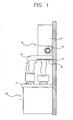
- Figure 1 is a side view showing a kitchen range hood installed at an upper side of a kitchen range in accordance with a conventional art.
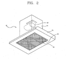
- FIG. 2 is an enlarged perspective view of the kitchen range hood in accordance with the conventional art.
- a conventional kitchen range hood 10 includes an exhaust duct 11; a blower 12 installed in the exhaust duct 11 and including a fan motor (not shown) and an exhaust fan (not shown); a hood cover 15 connected with the exhaust duct 11; and a filter 13 installed in the hood cover 15 and filtering a smell, dust or oil in the air sucked through the intake 14 of the hood cover 15.
- the kitchen range hood 10 is installed spaced apart with a certain interval at an upper side of the kitchen range 20.
- the exhaust duct 11 discharges externally air sucked through the intake 14.
- the conventional kitchen range hood 10 cannot discharge externally the whole of heat and contaminated air generated when cooking by using a front gas burner of the kitchen range 20, so a portion of the heat and contaminated air spreads toward a user positioned in front of the kitchen range hood 10, making the user feel uncomfortable.
- an object of the present invention is to provide an intake controlling device of a kitchen range hood capable of effectively discharging heat and contaminated air effectively through a kitchen range hood and thus maintaining an agreeable indoor environment.
- an intake controlling device of a kitchen range hood as defined in claim 1.
- An intake controlling device of a kitchen range hood capable of effectively discharging heat of a kitchen range hood and contaminated air and maintaining an agreeable indoor environment in accordance with preferred embodiments of the present invention with reference to Figures 3 to 8 .
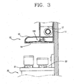
- Figure 3 is a side view showing the construction of the kitchen range hood in accordance with the present invention.
- the kitchen range hood 10 includes an exhaust duct 11; a blower 12 installed inside the exhaust duct 11 and including the fan motor (not shown) and an exhaust fan (not shown); a hood cover 15 connected with the exhaust duct 11; a filter 13 installed in the hood cover 15 and filtering a small and oil in the air sucked through an intake 14 of the hood cover 15; and an intake controlling device 100 installed at the hood cover 15 and selectively blocking opening regions of the intake 14.
- the intake controlling device 100 in accordance with the first embodiment of the present invention will now be described with reference to Figure 4 .
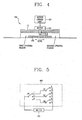
- Figure 4 shows a detailed construction of an intake controlling device of a kitchen range hood in accordance with a first embodiment of the present invention.
- the intake controlling device 100 includes an interception plate 102 installed at the hood cover 15 and selectively blocking a specific region (e.g., one of a first opening region, a second region and a central region) of the intake 14; a motor driving unit 103 for generating a motor drive signal for moving the interception plate 102 to the specific region of the intake 14 according to user's selection; and a motor 101 for moving the interception plate 102 to a specific region of the intake 14 according to the motor drive signal in order to block the specific region of the intake 14.
- a specific region e.g., one of a first opening region, a second region and a central region
- a motor driving unit 103 for generating a motor drive signal for moving the interception plate 102 to the specific region of the intake 14 according to user's selection
- a motor 101 for moving the interception plate 102 to a specific region of the intake 14 according to the motor drive signal in order to block the specific region of the intake 14.
- an uptake rate of the opening region is increased.
- the first opening region of the intake 14 installed at an upper side of the front gas burner 21 is opened and the second opening region of the intake 14 installed at an upper side of a back gas burner 22 is blocked, air is sucked only through the first opening region, making the uptake rate of the kitchen range hood is increased.
- a gas burner e.g., the front gas burner
- the central region is an in-between region of the first and second opening regions.
- Moving the interception plate 102 to a specific region can be implemented in a variable manner according to user's selection.
- FIG. 5 is a circuit diagram showing a detailed construction of a driving unit of the intake controlling device in accordance with the first embodiment of the present invention.
- the motor driving unit 103 includes: a user switch (US) for generating a switching signal for moving the interception plate 102 to a specific region (one of the first and second opening regions and the central region) of the intake 14; a front limit switch (SF) for receiving the switching signal of the US, and cutting off power supply to the motor 101 when the interception plate 102 is sensed, in order to move the interception plate 102 to the first opening region of the intake 14; a center limit switch (SC) for receiving the switching signal of the US, and cutting off power supply to the motor 101 when the interception plate 102 is sensed, in order to move the interception plate 102 to the central opening region of the intake 14; and a back limit switch (SB) for receiving the switching signal of the US, and cutting off power supply to the motor 101 when the interception plate 102 is sensed, in order to move the interception plate 102 to the second opening region of the intake 14.
- a user switch for generating a switching signal for moving the interception plate 102 to a specific region (one
- the motor 101 is driven when the US and the SF are simultaneously turned on, when the US and the SC are simultaneously turned on, or when the US and the SB are simultaneously turned on.
- the motor driving unit 103 moves the interception plate 102 to a specific region of the intake 14 by controlling the motor 101.
- the position of the interception plate 102 is determined by the user.
- the motor 101 when a terminal 'F' of the US is selected in order to block the first opening region of the intake 14, power is applied to the motor 101 through the front limit switch (SF) electrically connected with the terminal 'F' of the user switch (US), and the motor 101 is driven by power and moves the interception plate 102 to the first opening region.
- the SF cuts off power supply to the motor 101. Namely, when the SF contacts with the interception plate 102, the SF is turned off to cut off power applied to the motor 101, and accordingly, the interception plate 102 is stopped at the first opening region of the intake 14 to block it.
- the intake controlling device of the kitchen range hood in accordance with the first embodiment of the present invention freely moves the interception plate to the first opening region, the central region and the second opening region of the intake to increase the uptake rate of the kitchen range hood and thus, completely discharge heat, contaminated air and gases to outside.
- the front limit switch SF is fixedly installed at the left side of the intake controlling device
- the center limit switch SC is fixedly installed at the center of the intake controlling device
- the back limit switch SB is fixedly installed at the right side of the intake controlling device.
- An intake controlling device capable of completely discharge heat, contaminated gases to outside by increasing the uptake rate of the kitchen range hood by automatically moving the interception plate 102 to one of the first opening region, the central region and the second opening region according to a burner used in the kitchen range, rather than depending on user's selection, in accordance with the second embodiment of the present invention will now be described in detail with reference to Figures 6 to 8 .
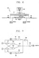
- Figure 6 shows a detailed construction of an intake controlling device of a kitchen range hood in accordance with a second embodiment of the present invention.
- an intake controlling device in accordance with the second embodiment of the present invention includes: an interception plate 102 installed at a hood cover 15 and selectively blocking opening regions of an intake 14; sensors 202 and 203 for sensing a current cooking position (e.g., the front burner 21) of the kitchen range 20 and generating a sense signal; a motor driving unit 201 for generating a motor drive signal for automatically moving the interception plate 102 to a specific region (e.g., the second opening region) of the intake 14 according to the sense signal; and a motor 101 for moving the interception plate 102 to a specific region (e.g., the second opening region) of the intake 14 according to the motor drive signal in order to block the specific region (e.g., the first opening region is opened and the second opening region is blocked) of the intake 14.
- sensors 202 and 203 for sensing a current cooking position (e.g., the front burner 21) of the kitchen range 20 and generating a sense signal
- a motor driving unit 201 for generating a motor
- Sensing of the current cooking position of the kitchen range 20 can be implemented in various manners.
- the first temperature sensor 202 is installed corresponding to an upper portion of the front burner 21 of the kitchen range 20, senses a temperature of the front burner 21, and outputs a first temperatures sense signal
- the second temperature sensor 203 is installed corresponding to an upper position of the back burner 22 of the kitchen range 20, senses a temperature of the back burner 22 and outputs a second temperature sense signal.
- an infrared sensor for sensing heat and steam generated from the kitchen range 20 is used as the first and second temperature sensors 202 and 203.
- the motor driving unit 201 When the motor driving unit 201 receives the first temperature sense signal, it moves the interception plate 102 to the second opening region. When the motor driving unit 201 receives the second temperature sense signal, it moves the interception plate 102 to the first opening region. When the motor driving unit 201 receives both first and second temperature sense signals, it moves the interception plate 102 to the central opening region.
- a controller for logically operating the first temperature sense signal, the second temperature sense signal, a switching signal of the front limit switch and a switching signal of the back limit switch and controlling the interception plate 102 can be added to the motor driving unit 201.
- the construction of the controller for logically operating the first temperature sense signal (IF), the second temperature sense signal (IB), a switching signal of the front limit switch (a first interception sense signal (SF1)) and a switching signal of the back limit switch (a second interception sense signal (SB1)) and controlling the interception plate 102 will be described in detail with reference to Figure 7 .
- Figure 7 is a circuit diagram of a controller of the intake controlling device in accordance with the second embodiment of the present invention.
- the controller includes: a first inverter IN1 for inverting the first interception sense signal (SF1); a first AND gate (AN1) for ANDing an output signal of the first inverter (IN1) and the second temperature sense signal (IB) of the second temperature sensor 203; a second inverter IN2 for inverting the second interception sense signal (SB1); a second AND gate (AN2) for ANDing an output signal of the second inverter IN2 and the first temperature sense signal (IF) of the first temperature sensor 202; a third inverter for inverting the second temperature sense signal (IB); a fourth inverter IN4 for inverting the first temperature sense signal (IF); a third AND gate (AN3) for ANDing an output signal of the third inverter IN3 and the first temperature sense signal (IF); a fourth AND gate (AN4) for ANDing an output signal of the fourth inverter (IN4) and the second temperature sense signal (IB); a first OR gate (OR1) for ORing an output signal of the
- Figure 8 is a truth table indicating an output value of the controller of the intake controlling device in accordance with the second embodiment of the present invention.
- the first temperature sensor 202 senses heat or steam generated during cooking and outputs a first temperature sense signal as '1'.
- the second temperature sensor 203 installed at an upper side of the back burner 22 of the kitchen range 20 does not sense heat and outputs a second temperature sense signal as '0'.
- the front limit switch (SF) outputs a first interception sense signal as '1', and if the interception plate 102 is not sensed, the front limit switch (SF) outputs the second interception sense signal as '0'.
- the controller receives the first and second temperature sense signals IF and IB and the first and second interception sense signals SF1 and SB1, logically operates them, and outputs a motor drive signal to the motor 1.
- the first inverter IN1 inverts the first interception signal SF1 to output an output signal '1'
- the first AND gate AN1 ANDs the first interception sense signal SF1 outputted from the first inverter IN1 and the temperature sense signal IB and outputs an output signal '0'.
- the second inverter IN2 inverts the second interception sense signal SB1 to output an output signal '1' and the second AND gate AN2 ANDs the second interception sense signal SB1 outputted from the second inverter IN2 and the first temperature sense signal IF and outputs an output signal '1'.
- the third AND gate AN3 ANDs the second temperature sense signal '1' inputted after being inverted in the third inverter IN3 and the first temperature sense signal '1', and outputs an output signal '1'.
- the forth AND gate AN4 ANDs the first temperature sense signal '0' inputted after being inverted in the fourth inverter IN4 and the second temperature sense signal '0', and outputs an output signal '0'.
- the first OR gate OR1 ORs output signals of the third AND gate AN3 and the fourth AND gate AN4 and outputs an output signal '1'.
- the second OR gate OR2 ORs output signals of the first AND gate AN1 and the second AND gate AN2, and outputs an output signal '1'.
- the fifth AND gate AN5 ANDs output signals of the first and second OR gates OR1 and OR2, and outputs an output signal '1' to the motor control switch MS. Then, the motor control signal MS applies power to the motor 101 according to the output signal '1' of the fifth AND gate AN5.
- the second AND gate AN2 When the interception plate 102 is sensed by the back limit switch (SB) and the second interception sense signal '1' is outputted, the second AND gate AN2 outputs an output signal '0'.
- the second OR gate OR2 ORs the output signal '0' outputted from the first AND gate AN1 and the output signal '0' outputted from the second AND gate AN2, and outputs an output signal '0'.
- the fifth AND gate AN5 outputs the output signal '0' to the motor control switch MS. Accordingly, the motor control switch MS cuts off power supply to the motor 101 according to the output signal '0' of the fifth AND gate AN5.
- the controller When the controller receives the first temperature sense signal '1' and the second temperature sense signal '1', it stops the motor 101 at the central region of the intake 14 in order to open both the first and second opening regions.
- the interception plate 102 of the intake controlling device is initially positioned at the central region.
- the intake controlling device of the kitchen range hood of the present invention has many advantages.
- the opening regions of the intake of the kitchen range hood are selectively opened and blocked according to a position where a smell and steam is generated during a cooking process, to thereby increase the uptake rate. Accordingly, performance of discharging heat and contaminated air of the kitchen range hood can be maximized, and thus, an indoor environment can be maintained to be agreeable.
Landscapes
- Engineering & Computer Science (AREA)
- Chemical & Material Sciences (AREA)
- Combustion & Propulsion (AREA)
- Mechanical Engineering (AREA)
- General Engineering & Computer Science (AREA)
- Ventilation (AREA)
Description
- The present invention relates to a kitchen range hood and, more particularly, to an intake controlling device of a kitchen range hood.
- In general, a kitchen range hood is installed at an upper side of a kitchen range, such as a gas range, an oven range, or the like, in order to exhaust heat, various kinds of smells, steam and gases such as CO2 or the like generated according to imperfect combustion. The kitchen range hood exhausts a gas or contaminated air and prevents a bad smell. The features of the preamble of
claim 1 are known fromJP-A-401210742 -
Figure 1 is a side view showing a kitchen range hood installed at an upper side of a kitchen range in accordance with a conventional art. -
Figure 2 is an enlarged perspective view of the kitchen range hood in accordance with the conventional art. - As shown in
Figure 2 , a conventionalkitchen range hood 10 includes anexhaust duct 11; ablower 12 installed in theexhaust duct 11 and including a fan motor (not shown) and an exhaust fan (not shown); ahood cover 15 connected with theexhaust duct 11; and afilter 13 installed in thehood cover 15 and filtering a smell, dust or oil in the air sucked through theintake 14 of thehood cover 15. - The
kitchen range hood 10 is installed spaced apart with a certain interval at an upper side of thekitchen range 20. Theexhaust duct 11 discharges externally air sucked through theintake 14. - However, as for the conventional
kitchen range hood 10, because the entire region of theintake 14 is formed smaller than a cooking region of thekitchen range 20, it fails to discharge externally heat and contaminated air generated during a cooking process entirely. - For example, the conventional
kitchen range hood 10 cannot discharge externally the whole of heat and contaminated air generated when cooking by using a front gas burner of thekitchen range 20, so a portion of the heat and contaminated air spreads toward a user positioned in front of thekitchen range hood 10, making the user feel uncomfortable. - In addition, since the portion of the heat and contaminated air, that has not been discharged externally, remains indoors, the indoor environment is not maintained agreeably.
- Therefore, an object of the present invention is to provide an intake controlling device of a kitchen range hood capable of effectively discharging heat and contaminated air effectively through a kitchen range hood and thus maintaining an agreeable indoor environment.
- To achieve these and other advantages and in accordance with the purpose of the present invention, as embodied and broadly described herein, there is provided an intake controlling device of a kitchen range hood as defined in
claim 1. - The foregoing and other objects, features, aspects and advantages of the present invention will become more apparent from the following detailed description of the present invention when taken in conjunction with the accompanying drawings.,
- The accompanying drawings, which are included to provide a further understanding of the invention and are incorporated in and constitute a part of this specification, illustrate embodiments of the invention and together with the description serve to explain the principles of the invention.
- In the drawings:
-
Figure 1 is a side view showing a kitchen range hood installed at an upper side of a kitchen range in accordance with a conventional art; -
Figure 2 is an enlarged perspective view showing the structure of the kitchen range hood in accordance with the conventional art; -
Figure 3 is a side view showing the construction of the kitchen range hood in accordance with the present invention; -
Figure 4 shows a detailed construction of an intake controlling device of a kitchen range hood in accordance with a first embodiment of the present invention; -
Figure 5 is a circuit diagram showing a detailed construction of a driving unit of the intake controlling device in accordance with the first embodiment of the present invention; -
Figure 6 shows a detailed construction of an intake controlling device of a kitchen range hood in accordance with a second embodiment of the present invention; -
Figure 7 is a circuit diagram of a controller of the intake controlling device in accordance with the second embodiment of the present invention; and -
Figure 8 is a truth table indicating an output value of the controller of the intake controlling device in accordance with the second embodiment of the present invention. - An intake controlling device of a kitchen range hood capable of effectively discharging heat of a kitchen range hood and contaminated air and maintaining an agreeable indoor environment in accordance with preferred embodiments of the present invention with reference to
Figures 3 to 8 . -
Figure 3 is a side view showing the construction of the kitchen range hood in accordance with the present invention. - With reference to
Figure 3 , thekitchen range hood 10 includes anexhaust duct 11; ablower 12 installed inside theexhaust duct 11 and including the fan motor (not shown) and an exhaust fan (not shown); ahood cover 15 connected with theexhaust duct 11; afilter 13 installed in thehood cover 15 and filtering a small and oil in the air sucked through anintake 14 of thehood cover 15; and an intake controllingdevice 100 installed at thehood cover 15 and selectively blocking opening regions of theintake 14. - The intake controlling
device 100 in accordance with the first embodiment of the present invention will now be described with reference toFigure 4 . -
Figure 4 shows a detailed construction of an intake controlling device of a kitchen range hood in accordance with a first embodiment of the present invention. - As shown in
Figure 4 , the intake controllingdevice 100 includes aninterception plate 102 installed at thehood cover 15 and selectively blocking a specific region (e.g., one of a first opening region, a second region and a central region) of theintake 14; amotor driving unit 103 for generating a motor drive signal for moving theinterception plate 102 to the specific region of theintake 14 according to user's selection; and amotor 101 for moving theinterception plate 102 to a specific region of theintake 14 according to the motor drive signal in order to block the specific region of theintake 14. - By blocking the first or second opening region of the
intake 14, an uptake rate of the opening region is increased. For example, when the first opening region of theintake 14 installed at an upper side of thefront gas burner 21 is opened and the second opening region of theintake 14 installed at an upper side of aback gas burner 22 is blocked, air is sucked only through the first opening region, making the uptake rate of the kitchen range hood is increased. Thus, because heat and contaminated air generated when cooking by using a gas burner (e.g., the front gas burner) of thekitchen range 20 can be discharged only through the first opening region of the kitchen range hood, the indoor environment can be agreeably maintained. - Meanwhile, when the second opening region of the
intake 14 installed at the upper side of theback gas burner 22 is opened and the first opening region of theintake 14 installed at the upper side of thefront gas burner 21 is blocked, air is sucked only through the second opening region, so the uptake rate of the kitchen range hood is increased. Accordingly, heat and contaminated air generated when cooking by using the gas burner 22 (e.g., back gas burner) of thekitchen range 20 are discharged only through the second opening region of the kitchen range hood and thus, the indoor environment can be agreeably maintained. - The central region is an in-between region of the first and second opening regions.
- Moving the
interception plate 102 to a specific region (e.g., one of the first and second regions and the central region) can be implemented in a variable manner according to user's selection. - An embodiment of the driving unit will be described with reference to
Figure 5 . -
Figure 5 is a circuit diagram showing a detailed construction of a driving unit of the intake controlling device in accordance with the first embodiment of the present invention. - As shown in
Figure 5 , themotor driving unit 103 includes: a user switch (US) for generating a switching signal for moving theinterception plate 102 to a specific region (one of the first and second opening regions and the central region) of theintake 14; a front limit switch (SF) for receiving the switching signal of the US, and cutting off power supply to themotor 101 when theinterception plate 102 is sensed, in order to move theinterception plate 102 to the first opening region of theintake 14; a center limit switch (SC) for receiving the switching signal of the US, and cutting off power supply to themotor 101 when theinterception plate 102 is sensed, in order to move theinterception plate 102 to the central opening region of theintake 14; and a back limit switch (SB) for receiving the switching signal of the US, and cutting off power supply to themotor 101 when theinterception plate 102 is sensed, in order to move theinterception plate 102 to the second opening region of theintake 14. - The
motor 101 is driven when the US and the SF are simultaneously turned on, when the US and the SC are simultaneously turned on, or when the US and the SB are simultaneously turned on. - The intake controlling device of the kitchen range hood in accordance with the first embodiment of the present invention will now be described with reference to
Figures 3 to 5 . , - First, when the US is selected by a user, the
motor driving unit 103 moves theinterception plate 102 to a specific region of theintake 14 by controlling themotor 101. In this case, the position of theinterception plate 102 is determined by the user. - For example, when a terminal 'F' of the US is selected in order to block the first opening region of the
intake 14, power is applied to themotor 101 through the front limit switch (SF) electrically connected with the terminal 'F' of the user switch (US), and themotor 101 is driven by power and moves theinterception plate 102 to the first opening region. When theinterception plate 102 comes in contact with the front limit switch SF, the SF cuts off power supply to themotor 101. Namely, when the SF contacts with theinterception plate 102, the SF is turned off to cut off power applied to themotor 101, and accordingly, theinterception plate 102 is stopped at the first opening region of theintake 14 to block it. - When the user selects a terminal 'C' of the user switch in order to block the central region of the
intake 14, power is applied to themotor 101 through the center limit switch (SC) electrically connected with the terminal 'C' and themotor 101 is driven by power and moves theinterception plate 102 to the central region. At this time, when theinterception plate 102 comes in contact with the center limit switch SC, the SC cuts off power supply to themotor 101. Namely, when the center limit switch SC contacts with theinterception plate 102, the SC is turned off to cut off power supply to themotor 101, and accordingly, theinterception plate 102 is stopped at the central region of theintake 14 to block it. - When the user selects a terminal 'B' of the US in order to block the second opening region of the
intake 14, power is applied to themotor 101 through the back limit switch SB electrically connected with the terminal 'B' and themotor 101 is driven by power to move theinterception plate 102 to the second opening region. At this time, when theinterception plate 102 comes in contact with the back limit switch SB, the SB cuts off power supply to themotor 101. Namely, when the SB contacts with theinterception plate 102, it cuts off power supply to themotor 101, and accordingly, theinterception plate 102 is stopped at the second opening region of theintake 14 to block it. - In this manner, the intake controlling device of the kitchen range hood in accordance with the first embodiment of the present invention freely moves the interception plate to the first opening region, the central region and the second opening region of the intake to increase the uptake rate of the kitchen range hood and thus, completely discharge heat, contaminated air and gases to outside.
- Preferably, the front limit switch SF is fixedly installed at the left side of the intake controlling device, the center limit switch SC is fixedly installed at the center of the intake controlling device and the back limit switch SB is fixedly installed at the right side of the intake controlling device.
- An intake controlling device capable of completely discharge heat, contaminated gases to outside by increasing the uptake rate of the kitchen range hood by automatically moving the
interception plate 102 to one of the first opening region, the central region and the second opening region according to a burner used in the kitchen range, rather than depending on user's selection, in accordance with the second embodiment of the present invention will now be described in detail with reference toFigures 6 to 8 . -
Figure 6 shows a detailed construction of an intake controlling device of a kitchen range hood in accordance with a second embodiment of the present invention. - As shown in
Figure 6 , an intake controlling device in accordance with the second embodiment of the present invention includes: aninterception plate 102 installed at ahood cover 15 and selectively blocking opening regions of anintake 14;sensors 202 and 203 for sensing a current cooking position (e.g., the front burner 21) of thekitchen range 20 and generating a sense signal; amotor driving unit 201 for generating a motor drive signal for automatically moving theinterception plate 102 to a specific region (e.g., the second opening region) of theintake 14 according to the sense signal; and amotor 101 for moving theinterception plate 102 to a specific region (e.g., the second opening region) of theintake 14 according to the motor drive signal in order to block the specific region (e.g., the first opening region is opened and the second opening region is blocked) of theintake 14. - Sensing of the current cooking position of the
kitchen range 20 can be implemented in various manners. For example, the first temperature sensor 202 is installed corresponding to an upper portion of thefront burner 21 of thekitchen range 20, senses a temperature of thefront burner 21, and outputs a first temperatures sense signal, and thesecond temperature sensor 203 is installed corresponding to an upper position of theback burner 22 of thekitchen range 20, senses a temperature of theback burner 22 and outputs a second temperature sense signal. Herein, preferably, an infrared sensor for sensing heat and steam generated from thekitchen range 20 is used as the first andsecond temperature sensors 202 and 203. - When the
motor driving unit 201 receives the first temperature sense signal, it moves theinterception plate 102 to the second opening region. When themotor driving unit 201 receives the second temperature sense signal, it moves theinterception plate 102 to the first opening region. When themotor driving unit 201 receives both first and second temperature sense signals, it moves theinterception plate 102 to the central opening region. - A controller for logically operating the first temperature sense signal, the second temperature sense signal, a switching signal of the front limit switch and a switching signal of the back limit switch and controlling the
interception plate 102 can be added to themotor driving unit 201. - The construction of the controller for logically operating the first temperature sense signal (IF), the second temperature sense signal (IB), a switching signal of the front limit switch (a first interception sense signal (SF1)) and a switching signal of the back limit switch (a second interception sense signal (SB1)) and controlling the
interception plate 102 will be described in detail with reference toFigure 7 . -
Figure 7 is a circuit diagram of a controller of the intake controlling device in accordance with the second embodiment of the present invention. - With reference to
Figure 7 , the controller includes: a first inverter IN1 for inverting the first interception sense signal (SF1); a first AND gate (AN1) for ANDing an output signal of the first inverter (IN1) and the second temperature sense signal (IB) of the second temperature sensor 203; a second inverter IN2 for inverting the second interception sense signal (SB1); a second AND gate (AN2) for ANDing an output signal of the second inverter IN2 and the first temperature sense signal (IF) of the first temperature sensor 202; a third inverter for inverting the second temperature sense signal (IB); a fourth inverter IN4 for inverting the first temperature sense signal (IF); a third AND gate (AN3) for ANDing an output signal of the third inverter IN3 and the first temperature sense signal (IF); a fourth AND gate (AN4) for ANDing an output signal of the fourth inverter (IN4) and the second temperature sense signal (IB); a first OR gate (OR1) for ORing an output signal of the third AND gate (AN3) and an output signal of the fourth AND gate (AN4); a second OR gate (OR2) for ORing an output signal of the first AND gate (AN1) and an output signal of the second AND gate (AN2); a fifth AND gate (AN5) for ANDing an output signal of the first OR gate (OR1) and an output signal of the second OR gate (OR2); and a motor control switch (MS) for outputting a motor drive signal to the motor 101 according to an output signal of the fifth AND gate (AN5). - When the motor control switch (MS) receives an output signal '1' from the fifth AND gate (AN5), it applies power to the
motor 101. When the motor control switch (MS) receives an output signal '0' from the fifth AND gate (AN5), it cuts off power supply to themotor 101. - The operation of the controller of the
intake controlling device 200 will be described in detail with reference toFigures 7 and8 . -
Figure 8 is a truth table indicating an output value of the controller of the intake controlling device in accordance with the second embodiment of the present invention. - When a user is cooking only with the
front burner 21 of thekitchen range 20, the first temperature sensor 202 senses heat or steam generated during cooking and outputs a first temperature sense signal as '1'. In this case, thesecond temperature sensor 203 installed at an upper side of theback burner 22 of thekitchen range 20 does not sense heat and outputs a second temperature sense signal as '0'. At this time, when theinterception plate 102 is sensed, the front limit switch (SF) outputs a first interception sense signal as '1', and if theinterception plate 102 is not sensed, the front limit switch (SF) outputs the second interception sense signal as '0'. - The controller receives the first and second temperature sense signals IF and IB and the first and second interception sense signals SF1 and SB1, logically operates them, and outputs a motor drive signal to the
motor 1. - For example, the first inverter IN1 inverts the first interception signal SF1 to output an output signal '1', and the first AND gate AN1 ANDs the first interception sense signal SF1 outputted from the first inverter IN1 and the temperature sense signal IB and outputs an output signal '0'.
- The second inverter IN2 inverts the second interception sense signal SB1 to output an output signal '1' and the second AND gate AN2 ANDs the second interception sense signal SB1 outputted from the second inverter IN2 and the first temperature sense signal IF and outputs an output signal '1'.
- The third AND gate AN3 ANDs the second temperature sense signal '1' inputted after being inverted in the third inverter IN3 and the first temperature sense signal '1', and outputs an output signal '1'.
- The forth AND gate AN4 ANDs the first temperature sense signal '0' inputted after being inverted in the fourth inverter IN4 and the second temperature sense signal '0', and outputs an output signal '0'.
- The first OR gate OR1 ORs output signals of the third AND gate AN3 and the fourth AND gate AN4 and outputs an output signal '1'.
- The second OR gate OR2 ORs output signals of the first AND gate AN1 and the second AND gate AN2, and outputs an output signal '1'.
- The fifth AND gate AN5 ANDs output signals of the first and second OR gates OR1 and OR2, and outputs an output signal '1' to the motor control switch MS. Then, the motor control signal MS applies power to the
motor 101 according to the output signal '1' of the fifth AND gate AN5. - When the
interception plate 102 is sensed by the back limit switch (SB) and the second interception sense signal '1' is outputted, the second AND gate AN2 outputs an output signal '0'. The second OR gate OR2 ORs the output signal '0' outputted from the first AND gate AN1 and the output signal '0' outputted from the second AND gate AN2, and outputs an output signal '0'. Then, the fifth AND gate AN5 outputs the output signal '0' to the motor control switch MS. Accordingly, the motor control switch MS cuts off power supply to themotor 101 according to the output signal '0' of the fifth AND gate AN5. - When the controller receives the first temperature sense signal '1' and the second temperature sense signal '1', it stops the
motor 101 at the central region of theintake 14 in order to open both the first and second opening regions. Herein, theinterception plate 102 of the intake controlling device is initially positioned at the central region. - As so far described, the intake controlling device of the kitchen range hood of the present invention has many advantages.
- That is, for example, the opening regions of the intake of the kitchen range hood are selectively opened and blocked according to a position where a smell and steam is generated during a cooking process, to thereby increase the uptake rate. Accordingly, performance of discharging heat and contaminated air of the kitchen range hood can be maximized, and thus, an indoor environment can be maintained to be agreeable.
Claims (3)
- An intake controlling device of a kitchen range hood comprising:- an intake (14) installed at the kitchen range hood, and including an opening region,characterized by:- a single interception plate (102) installed at the kitchen range hood for selectively blocking one of a first opening region, a central region and a second opening region of the intake (14) of the kitchen range hood; and- a motor driving unit (103) installed at the kitchen range hood for generating a motor drive signal for moving the interception plate (102) to one of the first opening region, the central region and the second opening region of the intake (14) according to user's selection; and- a motor (101) installed at the kitchen range hood for moving the interception plate to one of the first opening region, the central region and the second opening region of the intake (14) based on the motor drive signal, wherein the central region is an in-between region between the first and second opening regions of the intake (14).
- The device of claim 1, wherein the motor driving unit (103) comprises:- a user switch (US) for generating a switching signal for moving the interception plate (102) to one of the first and second opening regions and the central region of the intake (14);- a front limit switch (SF) for receiving the switching signal of the user switch, and cutting off power supply to the motor (101) when the interception plate is sensed, in order to position the interception plate at the first opening region of the intake;- a center limit switch (SC) for receiving the switching signal of the user switch, and cutting off power supply to the motor when the interception plate is sensed, in order to position the interception plate at the central opening region of the intake; and- a back limit switch (SB) for receiving the switching signal of the user switch, and cutting off power supply to the motor when the interception plate is sensed, in order to position the interception plate at the second opening region of the intake.
- The device of claim 2, wherein the motor driving unit (103) is configured such that the motor (101) is driven when the user switch (US) and the front limit switch (SF) are simultaneously turned on, when the user switch (US) and the center limit switch (SC) are simultaneously turned on, or when the user switch (US) and the back limit switch (SB) are simultaneously turned on.
Applications Claiming Priority (1)
| Application Number | Priority Date | Filing Date | Title |
|---|---|---|---|
| KR1020040103642A KR100690655B1 (en) | 2004-12-09 | 2004-12-09 | Intake interception plate driving apparatus of hood for range |
Publications (2)
| Publication Number | Publication Date |
|---|---|
| EP1669679A1 EP1669679A1 (en) | 2006-06-14 |
| EP1669679B1 true EP1669679B1 (en) | 2011-08-24 |
Family
ID=35355852
Family Applications (1)
| Application Number | Title | Priority Date | Filing Date |
|---|---|---|---|
| EP05290736A Not-in-force EP1669679B1 (en) | 2004-12-09 | 2005-04-04 | Intake controlling device of kitchen range hood |
Country Status (4)
| Country | Link |
|---|---|
| EP (1) | EP1669679B1 (en) |
| KR (1) | KR100690655B1 (en) |
| CN (1) | CN100478619C (en) |
| AU (1) | AU2005201368B2 (en) |
Cited By (1)
| Publication number | Priority date | Publication date | Assignee | Title |
|---|---|---|---|---|
| DE102023200817A1 (en) | 2023-02-01 | 2024-08-01 | BSH Hausgeräte GmbH | Control of an extractor hood |
Families Citing this family (7)
| Publication number | Priority date | Publication date | Assignee | Title |
|---|---|---|---|---|
| NL2002405C2 (en) * | 2009-01-09 | 2010-07-13 | Bos Exclusieve Fornuizen B V | EXTRACTION PLANT AND METHOD FOR VARIATING A FLUID FLOW OVER THE INLET SURFACE. |
| CN102366754A (en) * | 2011-09-27 | 2012-03-07 | 徐德胜 | Suspension suction hood |
| CN106765409A (en) * | 2017-01-01 | 2017-05-31 | 湖北中瑞天恒节能科技发展有限公司 | A kind of energy-saving stove oil fume pumping and removing method |
| CN106765410A (en) * | 2017-01-01 | 2017-05-31 | 湖北中瑞天恒节能科技发展有限公司 | A kind of energy-conserving oil pumping cigarette stove system |
| CN106996586B (en) * | 2017-05-18 | 2023-07-28 | 浙江帅康电气股份有限公司 | Fresh air linkage controller and range hood using same |
| CN107166463B (en) * | 2017-06-27 | 2019-08-02 | 苏州克莱尔环保科技有限公司 | A kind of intelligent range hood and its working method |
| CN114165821A (en) * | 2021-12-07 | 2022-03-11 | 佛山市顺德区美的电子科技有限公司 | Range hood, control method and device thereof and storage medium |
Family Cites Families (16)
| Publication number | Priority date | Publication date | Assignee | Title |
|---|---|---|---|---|
| US2554694A (en) * | 1945-06-06 | 1951-05-29 | Delbert F Belt | Odor eliminating apparatus |
| JPS5765529A (en) * | 1980-10-09 | 1982-04-21 | Misawa Homes Co Ltd | Ventilator |
| DE3436999A1 (en) * | 1984-10-09 | 1986-04-10 | Licentia Patent-Verwaltungs-Gmbh, 6000 Frankfurt | Vapour extraction device for arrangement above the hob of a cooker or the like |
| JPH01210742A (en) * | 1988-02-17 | 1989-08-24 | Matsushita Seiko Co Ltd | Air exhauster for cooking |
| DE8805325U1 (en) * | 1988-04-21 | 1988-07-07 | Bürcher-Siegrist, Rosmarie, 8029 Sauerlach | Extractor hood |
| DE4201209C2 (en) * | 1992-01-18 | 1994-06-01 | Miele & Cie | Extractor hood for arrangement above the hob of a kitchen range |
| JPH05322242A (en) * | 1992-05-15 | 1993-12-07 | Tokyo Gas Co Ltd | Air supplying and discharging method and device for kitchen room |
| CN2180915Y (en) * | 1993-03-24 | 1994-10-26 | 雷正 | Active smoke exhauster |
| CN2226714Y (en) * | 1995-07-06 | 1996-05-08 | 费文达 | Hanging fume and oil exhauster |
| KR19980069417A (en) * | 1997-02-28 | 1998-10-26 | 배순훈 | How to open / close the hood hood |
| KR20000061822A (en) * | 1999-03-31 | 2000-10-25 | 김윤규 | Hood moving type range hood using infrared sensor |
| JP2002286267A (en) * | 2001-03-28 | 2002-10-03 | Mitsubishi Electric Corp | Ventilator |
| NZ511487A (en) * | 2001-05-04 | 2002-12-20 | Swinghood Holdings Ltd | Rangehood with moveable inlet |
| US6765184B2 (en) * | 2002-07-26 | 2004-07-20 | Samsung Electronics Co., Ltd. | Smoke guiding apparatus of wall-mounted microwave oven |
| US20040206348A1 (en) * | 2002-07-30 | 2004-10-21 | Roger Bourassa | Hood extension for range and the like |
| KR100565253B1 (en) * | 2004-08-16 | 2006-03-30 | 엘지전자 주식회사 | Hood for range |
-
2004
- 2004-12-09 KR KR1020040103642A patent/KR100690655B1/en active IP Right Grant
-
2005
- 2005-03-31 AU AU2005201368A patent/AU2005201368B2/en not_active Ceased
- 2005-04-04 EP EP05290736A patent/EP1669679B1/en not_active Not-in-force
- 2005-05-30 CN CNB2005100740717A patent/CN100478619C/en not_active Expired - Fee Related
Cited By (2)
| Publication number | Priority date | Publication date | Assignee | Title |
|---|---|---|---|---|
| DE102023200817A1 (en) | 2023-02-01 | 2024-08-01 | BSH Hausgeräte GmbH | Control of an extractor hood |
| WO2024160616A1 (en) | 2023-02-01 | 2024-08-08 | BSH Hausgeräte GmbH | Control for an extractor hood |
Also Published As
| Publication number | Publication date |
|---|---|
| AU2005201368A1 (en) | 2006-06-29 |
| AU2005201368B2 (en) | 2007-03-15 |
| KR20060064952A (en) | 2006-06-14 |
| CN1786588A (en) | 2006-06-14 |
| KR100690655B1 (en) | 2007-03-09 |
| EP1669679A1 (en) | 2006-06-14 |
| CN100478619C (en) | 2009-04-15 |
Similar Documents
| Publication | Publication Date | Title |
|---|---|---|
| EP1669679B1 (en) | Intake controlling device of kitchen range hood | |
| EP1498663B1 (en) | Microwave oven with air cleaning function and method for operating the same | |
| US7069923B2 (en) | Apparatus and method of controlling fan motor in downdraft gas range | |
| JP2006240403A (en) | Air-conditioning device for vehicle | |
| CN111998398A (en) | Range, range hood linkage system and method for same | |
| JP4049461B2 (en) | Intake door control device | |
| JP2002286267A (en) | Ventilator | |
| KR100529243B1 (en) | Apparatus and method controlling range hood | |
| KR20040072198A (en) | Hood combined microwave oven | |
| JP2002061908A (en) | Vent air amount automatic control system | |
| JP2000356407A (en) | Air conditioner | |
| JPH01247933A (en) | Range hood linked to range | |
| JPS6124802Y2 (en) | ||
| JPH03144238A (en) | Automatic operating device for range hood | |
| JPH04327760A (en) | Control device for air conditioner with air purifying function | |
| JPH0270518A (en) | Mode shifting device in air conditioning equipment for automobile | |
| KR970011181B1 (en) | Hood for microwave oven | |
| JPH01210742A (en) | Air exhauster for cooking | |
| JP2004322900A (en) | Switch control device for vehicle | |
| JPH0453079B2 (en) | ||
| KR950033280A (en) | Microwave Multifunction Selection Controller | |
| JPH04236036A (en) | Device for automatically operating range hood | |
| KR20050038552A (en) | Automatic ashtray device | |
| JPS5918013A (en) | Operation control display unit of air conditioner for automobile | |
| JPS584253B2 (en) | air conditioner |
Legal Events
| Date | Code | Title | Description |
|---|---|---|---|
| PUAI | Public reference made under article 153(3) epc to a published international application that has entered the european phase |
Free format text: ORIGINAL CODE: 0009012 |
|
| 17P | Request for examination filed |
Effective date: 20050409 |
|
| AK | Designated contracting states |
Kind code of ref document: A1 Designated state(s): AT BE BG CH CY CZ DE DK EE ES FI FR GB GR HU IE IS IT LI LT LU MC NL PL PT RO SE SI SK TR |
|
| AX | Request for extension of the european patent |
Extension state: AL BA HR LV MK YU |
|
| AKX | Designation fees paid |
Designated state(s): DE FR IT |
|
| 17Q | First examination report despatched |
Effective date: 20090918 |
|
| GRAP | Despatch of communication of intention to grant a patent |
Free format text: ORIGINAL CODE: EPIDOSNIGR1 |
|
| GRAS | Grant fee paid |
Free format text: ORIGINAL CODE: EPIDOSNIGR3 |
|
| GRAA | (expected) grant |
Free format text: ORIGINAL CODE: 0009210 |
|
| AK | Designated contracting states |
Kind code of ref document: B1 Designated state(s): DE FR IT |
|
| REG | Reference to a national code |
Ref country code: DE Ref legal event code: R096 Ref document number: 602005029696 Country of ref document: DE Effective date: 20111020 |
|
| PG25 | Lapsed in a contracting state [announced via postgrant information from national office to epo] |
Ref country code: IT Free format text: LAPSE BECAUSE OF FAILURE TO SUBMIT A TRANSLATION OF THE DESCRIPTION OR TO PAY THE FEE WITHIN THE PRESCRIBED TIME-LIMIT Effective date: 20110824 |
|
| PLBE | No opposition filed within time limit |
Free format text: ORIGINAL CODE: 0009261 |
|
| STAA | Information on the status of an ep patent application or granted ep patent |
Free format text: STATUS: NO OPPOSITION FILED WITHIN TIME LIMIT |
|
| 26N | No opposition filed |
Effective date: 20120525 |
|
| REG | Reference to a national code |
Ref country code: DE Ref legal event code: R097 Ref document number: 602005029696 Country of ref document: DE Effective date: 20120525 |
|
| REG | Reference to a national code |
Ref country code: FR Ref legal event code: ST Effective date: 20121228 |
|
| PG25 | Lapsed in a contracting state [announced via postgrant information from national office to epo] |
Ref country code: FR Free format text: LAPSE BECAUSE OF NON-PAYMENT OF DUE FEES Effective date: 20120430 |
|
| PGFP | Annual fee paid to national office [announced via postgrant information from national office to epo] |
Ref country code: DE Payment date: 20160421 Year of fee payment: 12 |
|
| REG | Reference to a national code |
Ref country code: DE Ref legal event code: R119 Ref document number: 602005029696 Country of ref document: DE |
|
| PG25 | Lapsed in a contracting state [announced via postgrant information from national office to epo] |
Ref country code: DE Free format text: LAPSE BECAUSE OF NON-PAYMENT OF DUE FEES Effective date: 20171103 |