EP1669673A1 - Pilot safety shut off device for gas - Google Patents
Pilot safety shut off device for gas Download PDFInfo
- Publication number
- EP1669673A1 EP1669673A1 EP04788290A EP04788290A EP1669673A1 EP 1669673 A1 EP1669673 A1 EP 1669673A1 EP 04788290 A EP04788290 A EP 04788290A EP 04788290 A EP04788290 A EP 04788290A EP 1669673 A1 EP1669673 A1 EP 1669673A1
- Authority
- EP
- European Patent Office
- Prior art keywords
- pipe
- male terminal
- shaped male
- shaped
- terminal
- Prior art date
- Legal status (The legal status is an assumption and is not a legal conclusion. Google has not performed a legal analysis and makes no representation as to the accuracy of the status listed.)
- Granted
Links
Images







Classifications
-
- F—MECHANICAL ENGINEERING; LIGHTING; HEATING; WEAPONS; BLASTING
- F23—COMBUSTION APPARATUS; COMBUSTION PROCESSES
- F23N—REGULATING OR CONTROLLING COMBUSTION
- F23N5/00—Systems for controlling combustion
- F23N5/24—Preventing development of abnormal or undesired conditions, i.e. safety arrangements
- F23N5/245—Preventing development of abnormal or undesired conditions, i.e. safety arrangements using electrical or electromechanical means
-
- F—MECHANICAL ENGINEERING; LIGHTING; HEATING; WEAPONS; BLASTING
- F23—COMBUSTION APPARATUS; COMBUSTION PROCESSES
- F23N—REGULATING OR CONTROLLING COMBUSTION
- F23N5/00—Systems for controlling combustion
- F23N5/02—Systems for controlling combustion using devices responsive to thermal changes or to thermal expansion of a medium
- F23N5/10—Systems for controlling combustion using devices responsive to thermal changes or to thermal expansion of a medium using thermocouples
- F23N5/107—Systems for controlling combustion using devices responsive to thermal changes or to thermal expansion of a medium using thermocouples using mechanical means, e.g. safety valves
-
- F—MECHANICAL ENGINEERING; LIGHTING; HEATING; WEAPONS; BLASTING
- F23—COMBUSTION APPARATUS; COMBUSTION PROCESSES
- F23Q—IGNITION; EXTINGUISHING-DEVICES
- F23Q9/00—Pilot flame igniters
- F23Q9/08—Pilot flame igniters with interlock with main fuel supply
- F23Q9/12—Pilot flame igniters with interlock with main fuel supply to permit the supply to the main burner in dependence upon existence of pilot flame
-
- H—ELECTRICITY
- H01—ELECTRIC ELEMENTS
- H01R—ELECTRICALLY-CONDUCTIVE CONNECTIONS; STRUCTURAL ASSOCIATIONS OF A PLURALITY OF MUTUALLY-INSULATED ELECTRICAL CONNECTING ELEMENTS; COUPLING DEVICES; CURRENT COLLECTORS
- H01R4/00—Electrically-conductive connections between two or more conductive members in direct contact, i.e. touching one another; Means for effecting or maintaining such contact; Electrically-conductive connections having two or more spaced connecting locations for conductors and using contact members penetrating insulation
- H01R4/10—Electrically-conductive connections between two or more conductive members in direct contact, i.e. touching one another; Means for effecting or maintaining such contact; Electrically-conductive connections having two or more spaced connecting locations for conductors and using contact members penetrating insulation effected solely by twisting, wrapping, bending, crimping, or other permanent deformation
- H01R4/18—Electrically-conductive connections between two or more conductive members in direct contact, i.e. touching one another; Means for effecting or maintaining such contact; Electrically-conductive connections having two or more spaced connecting locations for conductors and using contact members penetrating insulation effected solely by twisting, wrapping, bending, crimping, or other permanent deformation by crimping
- H01R4/183—Electrically-conductive connections between two or more conductive members in direct contact, i.e. touching one another; Means for effecting or maintaining such contact; Electrically-conductive connections having two or more spaced connecting locations for conductors and using contact members penetrating insulation effected solely by twisting, wrapping, bending, crimping, or other permanent deformation by crimping for cylindrical elongated bodies, e.g. cables having circular cross-section
- H01R4/184—Electrically-conductive connections between two or more conductive members in direct contact, i.e. touching one another; Means for effecting or maintaining such contact; Electrically-conductive connections having two or more spaced connecting locations for conductors and using contact members penetrating insulation effected solely by twisting, wrapping, bending, crimping, or other permanent deformation by crimping for cylindrical elongated bodies, e.g. cables having circular cross-section comprising a U-shaped wire-receiving portion
- H01R4/185—Electrically-conductive connections between two or more conductive members in direct contact, i.e. touching one another; Means for effecting or maintaining such contact; Electrically-conductive connections having two or more spaced connecting locations for conductors and using contact members penetrating insulation effected solely by twisting, wrapping, bending, crimping, or other permanent deformation by crimping for cylindrical elongated bodies, e.g. cables having circular cross-section comprising a U-shaped wire-receiving portion combined with a U-shaped insulation-receiving portion
-
- H—ELECTRICITY
- H01—ELECTRIC ELEMENTS
- H01R—ELECTRICALLY-CONDUCTIVE CONNECTIONS; STRUCTURAL ASSOCIATIONS OF A PLURALITY OF MUTUALLY-INSULATED ELECTRICAL CONNECTING ELEMENTS; COUPLING DEVICES; CURRENT COLLECTORS
- H01R4/00—Electrically-conductive connections between two or more conductive members in direct contact, i.e. touching one another; Means for effecting or maintaining such contact; Electrically-conductive connections having two or more spaced connecting locations for conductors and using contact members penetrating insulation
- H01R4/58—Electrically-conductive connections between two or more conductive members in direct contact, i.e. touching one another; Means for effecting or maintaining such contact; Electrically-conductive connections having two or more spaced connecting locations for conductors and using contact members penetrating insulation characterised by the form or material of the contacting members
- H01R4/66—Connections with the terrestrial mass, e.g. earth plate, earth pin
-
- F—MECHANICAL ENGINEERING; LIGHTING; HEATING; WEAPONS; BLASTING
- F23—COMBUSTION APPARATUS; COMBUSTION PROCESSES
- F23N—REGULATING OR CONTROLLING COMBUSTION
- F23N2900/00—Special features of, or arrangements for controlling combustion
- F23N2900/05101—Connections between thermocouple and magnetic valves, e.g. by plug and socket connectors
-
- H—ELECTRICITY
- H01—ELECTRIC ELEMENTS
- H01R—ELECTRICALLY-CONDUCTIVE CONNECTIONS; STRUCTURAL ASSOCIATIONS OF A PLURALITY OF MUTUALLY-INSULATED ELECTRICAL CONNECTING ELEMENTS; COUPLING DEVICES; CURRENT COLLECTORS
- H01R4/00—Electrically-conductive connections between two or more conductive members in direct contact, i.e. touching one another; Means for effecting or maintaining such contact; Electrically-conductive connections having two or more spaced connecting locations for conductors and using contact members penetrating insulation
- H01R4/58—Electrically-conductive connections between two or more conductive members in direct contact, i.e. touching one another; Means for effecting or maintaining such contact; Electrically-conductive connections having two or more spaced connecting locations for conductors and using contact members penetrating insulation characterised by the form or material of the contacting members
- H01R4/64—Connections between or with conductive parts having primarily a non-electric function, e.g. frame, casing, rail
- H01R4/643—Connections between or with conductive parts having primarily a non-electric function, e.g. frame, casing, rail for rigid cylindrical bodies
Definitions
- the present invention relates to a gas burner safety device which is employed to a gas cooking stove, a gas water heater, and the like. More particularly, it relates to a gas burner safety device to which a thermo-couple unit and an electromagnetic valve unit which is operated by electricity generated with thermoelectric power are integrally coupled.
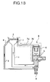
- a gas cooking stove system as shown in Fig. 13 for example is known.
- This system comprises a main burner 2 disposed at the upper end of a gas supply conduit 1, a lighting burner 4 disposed at the top end of an assist supply conduit 3 which separates from the gas supply conduit 1, a gas burner safety device 8 to which an electromagnetic valve unit 6 having a valve body 5 to open and close the passage of the gas supply conduit 1 and a thermo-couple unit 7 having cables 7a', 7b'connected to the electromagnetic unit 6 are integrally arranged, an operating shaft 9, and so on, as disclosed in Japanese Patent Laid-open 2000-18591 and H8-178296.
- thermoelectric power is generated at the thermo-couple unit 7, and the electricity generated by the thermoelectric power flows in a coil of the electromagnetic valve unit 6 to generate electromagnetic power. In this manner, the valve body 5 is sucked and maintains the gas passage at an opened state.
- thermo-couple unit 7 When the flame of the main burner 2 is extinguished by blow-off, boil-spill or the like, the heating to the thermo-couple unit 7 is interrupted and the thermoelectric power, namely the electromagnetic force, is extinguished. Then, the valve body 5 is returned by a return spring and the gas passage is closed. In this manner, emission of unburned gas is prevented.
- the electronic valve unit 6 and the thermo-couple unit 7 are electrically connected by connecting two male terminals 6a, 6b disposed at the electromagnetic valve unit 6 side with two female terminals 7a, 7b disposed at the thermo-couple unit 7 side. Accordingly, two pairs of male terminals 6a, 6b and female terminals 7a, 7b which are almost the same shape are disposed in parallel with each other for coupling freely to be attached and detached.
- thermo-couple unit 7 comprises cables 7a', 7b'which are respectively connected to the female terminal 7a, 7b, a pole-shaped conductive member 7a" as the thermal sensitive portion which is disposed at the top end of the cables 7a', 7b', a pipe-shaped conductive member 7b" which is disposed around and connected to the pole-shaped conductive member 7a" with the top end portion which is formed as a tapered cone-shape, and a pipe-shaped conductive member 7b'''which diameter is ⁇ D.
- a hot junction part P1 is formed at the top end portion at which the pole-shaped conductive member 7a" and the pipe-shaped conductive member 7b" are connected, and a cold junction part P2, P3 is formed at a specific distance apart from the hot junction part P1.
- thermo-couple unit 7 Furthermore, performances, such as high thermoelectric power, quick response, etc, are needed for the thermo-couple unit 7 to be able to precisely detect the extinguishment of the gas flame. Therefore, to achieve downsizing, cost-reduction and the like as the whole device, the performance has to be obtained without enlargement, cost-up and the like of the thermal sensitive portion (7a", 7b",7b"').
- the present invention was devised in view of the abovementioned circumstances of the related art.
- the object of the present invention is to provide a gas burner safety device with improved performance reliability, while achieving downsizing, cost-reduction, assembling facilitation, etc. of the device.
- a gas burner safety device of the present invention comprises a thermo-couple unit having two terminals connected to a thermal sensitive portion, and an electromagnetic valve unit having two terminals connected to a coil for magnetizing and respectively connected to the two terminals of the thermo-couple unit and a valve body driven by electromagnetic force generated by powering to the coil, and either two terminals of the thermo-couple unit or the electromagnetic valve unit comprise a pipe-shaped male terminal having at least an arc-shaped portion of a cylinder and either of an inner male terminal and an inner female terminal which is disposed inside the pipe-shaped male terminal, and the other two terminals of the thermo-couple unit or the electromagnetic valve unit comprise an outer female terminal connected to at least one side of the inside and the outside of the wall face of the pipe-shaped male terminal and the other of the inner male terminal and the inner female terminal which is disposed inside the pipe-shaped male terminal.
- the pipe-shaped male terminal which is disposed in either of the thermo-couple unit and the electromagnetic valve unit is connected to the outer female terminal which is disposed in the other of the thermo-couple unit and the electromagnetic valve unit.
- Either of the inner female terminal and the inner male terminal which is disposed in the axis direction at the center axis position of the pipe-shaped male terminal is connected to the other of the inner female terminal and the inner male terminal which is disposed in the unit without the pipe-shaped male terminal.
- the terminals can be disposed in parallel to the axis direction of the pipe-shaped male terminal.
- the device can be downsized in width and in size. Further, since the pipe-shaped male terminal can be connected to the outer female terminal at any position in the arc direction of the pipe-shaped male terminal, the attaching angle between the thermo-couple unit and the electromagnetic valve unit can be flexible when connecting.
- the inner female terminal has a pair of spring pieces which can sandwich the inner male terminal
- the outer female terminal has a pair of spring pieces which can sandwich the wall face of the pipe-shaped male terminal both from the inside and the outside.
- the inner female terminal and the outer female terminal are folded approximately in a V-shape to have a flexible piece, and the pipe-shaped male terminal and the inner male terminal are inserted and detached in the direction approximately perpendicular to the deforming direction of the flexible piece.
- the connecting pressure between the male terminal (the pipe-shaped male terminal and the inner male terminal) and the female terminal (the inner female terminal and the outer female terminal) is exerted approximately even in the direction of inserting and detaching. Therefore, stable electrical contact can be obtained reliably.
- pin-shaped male terminal does not project from the pipe-shaped male terminal and stays inside at the state that the electromagnetic valve unit and the thermo-couple unit are separated, breakage etc. of the pin-shaped male terminal can be prevented.
- the thickness of the pipe-shaped male terminal is the same dimension as the outer diameter of the inner male terminal.
- thermo-couple unit or the electromagnetic valve unit comprises the inner female terminal and the outer female terminal , and further comprises a fit portion which retains the inner female terminal and is fitted inside the pipe-shaped male terminal, and a sandwich piece which retains the outer female terminal and sandwiches the pipe-shaped male terminal from the outside in cooperation with the outer circumference of the fit portion.
- thermo-couple unit and the electromagnetic valve unit are connected.
- the fit portion is fitted inside the pipe-shaped male terminal, and the pin-shaped male terminal is connected to the inner female terminal which is surrounded by the fit portion.
- the sandwich piece sandwiches the pipe shaped male terminal in cooperation with the outer circumference of the fit portion, and the inner face and the outer face of the pipe-shaped male terminal are connected to the outer female terminal. In this manner, reliable electric connection can be obtained.
- the pipe-shaped male terminal is formed with almost even thickness and the fit portion is formed approximately cylindrical to match with the pipe-shaped male terminal.
- thermo-couple unit the pipe-shaped male terminal (the electromagnetic valve unit) which is formed cylindrical and the fit portion (the thermo-couple unit) which is formed approximately cylindrical to match with the pipe-shaped male terminal are fitted to be point symmetry around the axis. Therefore, the thermo-couple unit and the electromagnetic valve unit can be fitted in the direction of any angle without caring about the orientation, and the assembling operation can be easily performed.
- the pipe-shaped male terminal has a folded portion which top end portion is folded inside, and the fit portion has a pawl portion for latching with the folded portion.
- the fit portion (the thermo-couple unit) is fitted to the pipe-shaped male terminal (the electromagnetic valve unit)
- the pawl portion of the fit portion latches the folded portion of the pipe-shaped male terminal. Accordingly, detachment of the fit portion from the pipe-shaped male terminal can be prevented.
- the fit portion has a deform portion which can elastically deform in the direction perpendicular to the direction of fitting to the pipe-shaped male terminal, and the pawl portion is formed at the top end of the deform portion.
- the deform portion elastically returns and the pawl portion disposed at the top end thereof latches the folded portion of the pipe-shaped male terminal. Accordingly, the fitting operation of the fit portion (the thermo-couple unit) and the pipe-shaped male terminal (the electromagnetic valve unit) can easily be performed, and easy detachment of the fit portion from the pipe-shaped male terminal can be prevented.
- the pipe-shaped male terminal integrally has an attachment flange for fixing the electromagnetic valve unit at a desired position.
- the gas burner safety device which comprises the electromagnetic valve unit and the thermo-couple unit can be fixed.
- the pipe-shaped male terminal integrally has a screw cap for fixing the electromagnetic valve unit at a desired position.
- the gas burner safety device which comprises the electromagnetic valve unit and the thermo-couple unit can be fixed.
- the electromagnetic valve unit has a movable core which is integrally movable with the valve body and a fixed core on which the coil is wound, and the pipe-shaped male terminal integrally has a holder for retaining the fixed core.
- a gas burner safety device of the present invention comprises a thermo-couple unit having a thermal sensitive portion at the top end thereof, and an electromagnetic valve unit which is driven by electromagnetic force based on thermoelectric power generated at the thermo-couple unit, and the thermal sensitive portion of the thermo-couple unit includes a pole-shaped conductive member and a pipe-shaped conductive member which is cylindrically disposed around and connected to the pole-shaped conductive member with the top end portion which is formed as a cone shape, and the pipe-shaped conductive member is formed so that the thickness at a cold junction part of the rear end side is larger than that at a hot junction part of the top end to which the pole-shaped conductive member is connected.
- thermoelectric power characteristics and response can be improved.
- a top end thin portion which outer diameter is the smallest is formed at the top end connecting region of the pole-shaped conductive member and the pipe-shaped conductive member, and the length of the top end thin portion is formed at about 30 through 50 percent of the distance from the hot junction part to the cold junction part.
- thermoelectric power characteristics and response can be improved (namely obtaining higher thermoelectric power and quicker response).
- the two terminals at the electromagnetic valve unit side and the two terminals at the thermo-couple unit side are disposed in the same axis direction. Therefore, the device can be aggregated and the device can be brought down in width and in size. Further, in the unit having the pipe-shaped male terminal, by disposing the other terminal is at the center axis position of the pipe-shaped male terminal, the pipe-shaped male terminal can be fitted and connected to the outer female terminal of the other unit at any angle having the center axis as the center. In this manner, flexibility of the attaching angle between the thermo-couple unit and the electromagnetic valve unit at the time of connecting can be improved, and assembling operation can easily be performed.
- thermoelectric power characteristics and response can be improved.
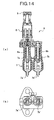
- Fig. 1 through 7 show an embodiment of a gas burner safety device of the present invention.
- Fig. 1 shows a front view and a side view of the whole device.
- Fig. 2 is a sectional view of the device in the axis direction.
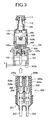
- Fig. 3 is a sectional view showing the state that an electromagnetic valve unit and a thermo-couple unit are separated.
- Fig. 4 is sectional view of the device in the direction perpendicular to the axis of the device.
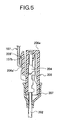
- Fig. 5 is a sectional view showing a part of the device.
- Fig. 6 is a partial view showing the structure of the terminals.
- Fig. 7 has a side view and a sectional view showing a thermal sensitive portion of the thermo-couple unit.
- the electromagnetic valve unit 100 and the thermo-couple unit 200 are coupling freely to be attached and detached.
- the electromagnetic valve unit 100 comprises a fixed core 101, a resin-made bobbin 102 to support the fixed core 101, a coil 103 for magnetization which integrally wounds on the fixed core 101 and the bobbin 102, a conductive holder 104 to fix the bobbin 102 by calking, a pin-shaped male terminal 105 which is connected to one end 103a of the coil 103 and constitutes one portion of a pair of male terminals, an insulate member 106 to retain the pin-shaped male terminal 105 at the center of the holder 104 while performing electrical insulation therebetween, a pipe-shaped male terminal 107 made of conductive material which is connected to the holder 104 and constitutes the other portion of the pair of male terminals, a resin-made case 108 to cover the fixed core 101, a movable core 110 fixed at one end of a shaft 109 which is slidably supported by the case 108, a rubber-made valve body 111 fixed at the other end of the shaft
- the fixed core 101 is made of magnetic material, such as permalloy, and is formed approximately into a U-shape.
- the bobbin 102 is made of isolating material (non-conductive material), and is formed approximately into an inverted U-shape. At the state that the fixed core 101 is supported by the bobbin 102, the bobbin 102 and the fixed core 101 are formed approximately into an H-shape, and the coil 103 is wound thereon as the longitudinal winding.
- the holder 104 is made of conductive material, such as brass, and the top end portion thereof is calked to fix the bobbin 102.
- the other end 103b of the coil 103 is electrically connected to the top end of the holder 104 by hot welding, cold welding, and so on.
- the pin-shaped male terminal 105 is made of conductive material, and formed as a tapered cylindrical shape (a needle shape) which top end is closed. Then, it is retained at the center of the holder 104 without any contact thereto by the isolate member 106.
- the pipe-shaped male terminal 107 is made of conductive material, such as a metal plate which is of a specific thickness, and is formed cylindrical having an approximately rhomboid attachment flange 107a integrally at the top end. Further, a folded portion 107b is formed by folding the end edge portion inside. Then, the pipe-shaped male terminal 107 functions as the second connector which is fitted to (the below-mentioned first connector 206 of) the thermo-couple unit 200.
- the relation between the pipe-shaped male terminal 107 and the pin-shaped male terminal 105 is shown in Fig. 3.
- the pin-shaped male terminal 105 is disposed at the inside center of the pipe-shaped male terminal 107.
- the pipe-shaped male terminal 107 is formed to be longer than the pin-shaped male terminal by dimension L, so that the pin-shaped male terminal 105 does not project from the pipe-shaped male terminal 107.
- the pin-shaped male terminal does not directly contact anything, even if it drops or hits other parts. Therefore, bending, breakage and the like can be prevented.
- the pipe-shaped male terminal 107 is formed so that the thickness including the folded portion 107b is the same as the diameter of the pin-shaped male terminal 105.
- the same parts can be used for both an inner female terminal 204 and an outer female terminal 205, which is described later.
- the thermo-couple unit 200 comprises a thermal sensitive portion 201 formed at the top end, a first cable 202 and a second cable 203 which are drawn from the thermal sensitive portion 201, the inner female terminal 204 which is connected to an end portion of the first cable 202 and constitutes one portion of a pair of female terminals, the outer female terminal 205 which is connected to an end portion of the second cable 203 and constitutes the other portion of the pair of female terminals, the first connector 206 to retain the inner female terminal and the outer female terminal 205, a seal member 207 to seal an end portion of the first connector 206, and so on.
- the thermal sensitive portion 201 comprises a pole-shaped conductive member 201a which is connected to the first cable 202, a pipe-shaped conductive member 201b which is disposed cylindrically around the pole-shaped conductive member 201a and connected to the pole-shaped conductive member 201a at the top end which is formed conical, a second pipe-shaped conductive member 201c which connects the pipe-shaped conductive member 201b to the first cable 203, and so on.
- the pole-shaped conductive member 201a is made of alloy material of Ni, Cu and Mn, and forms a solid shape.
- the pipe-shaped conductive member 201b is made of alloy material of Ni, Cr and Fe, and the top end is formed conical and the bottom end is formed cylindrical.
- the thickness at the conical region is thinner than that at the cylindrical region.
- the outer diameter at the cylindrical region of the pipe-shaped conductive member 201b is smaller than that of the related art shown in Fig. 13.
- the second pipe-shaped conductive member 201c is formed cylindrical with a diameter ⁇ Dl which is smaller than the diameter of the related art in Fig. 13 ( ⁇ D1 ⁇ D).
- a hot junction part P1 is formed at the top end region at which the pole-shaped conductive member 201a and the pipe-shaped conductive member 201b are connected, and a cold junction part P2, P3 is formed at a position which is apart from the hot junction part P1 toward the rear by a specific distance.
- the rear side of the pipe-shaped conductive member 201b namely the cold junction part P2 is formed thicker than the warm junction P1. Therefore, even though the diameter of the pipe-shaped conductive member 201b is smaller than that of the related art, the same thermoelectric power characteristics and response can be maintained. In this manner, downsizing and cost-reduction can be achieved.
- the top end thin portion which outer diameter ⁇ d is the smallest is defined.
- the length L1 of the top end thin portion is formed at about 30 through 50 percent of the distance between the hot junction part P1 and the cold junction part P2.
- the dimension L1 is set to be longer than the dimension L of the related art shown in Fig. 13, and contributes to high thermoelectric power and quick response.
- thermoelectric power characteristics and response improve further.
- the inner female terminal 204 has a pair of spring pieces 204a, 204a which is formed to be able to sandwich the pin-shaped male terminal 105 along the axis from both outer sides in the diameter direction of the circumference face.
- the pair of spring pieces 204a, 204a is respectively folded approximately in a V-shape, and has a pair of flexible pieces 204a', 204a' which can contact both sides of the circumference face of the pin-shaped male terminal 105 while facing each other.
- the pin-shaped male terminal 105 is free to be inserted and detached in the direction (the direction being perpendicular to the paper face of Fig.4 (a), (b)) which is approximately perpendicular to the deforming direction (the direction being horizontal to Fig. 4 (a), (b)) of the pair of flexible pieces 204a', 204a'.
- the outer female terminal 205 is formed as approximately the same shape as the inner female terminal 204. As shown in Fig. 3 and Fig. 4, the outer female terminal 205 has a pair of spring pieces 205a, 205a which is formed to be able to sandwich the wall face of the pipe-shaped male terminal 107 from both the inside and the outside. As shown in Fig. 4 (b), the pair of spring pieces 205a, 205a is respectively folded approximately in a V-shape, and has a pair of flexible pieces 205a', 205a' which can contact to both sides of the inner circumference and the outer circumference of the pipe-shaped male terminal 107 as facing each other.
- the pipe-shaped male terminal 107 is free to be inserted and detached in the direction (the direction being perpendicular to the paper face of Fig.4 (a), (b)) which is approximately perpendicular to the deforming direction (the direction being horizontal to Fig. 4 (a), (b)) of the pair of flexible pieces 204a', 204a'.
- the first connector 206 comprises a fit portion 206a which is fitted to the inside of the pipe-shaped male terminal 107 to retain the inner female terminal 204, a sandwich piece 206b which retains the outer female terminal 205 in cooperation with the outer circumference of the fit portion 206a and which sandwiches the pipe-shaped male terminal 107 from the outside, and so on.
- the fit portion 206 is formed to include a deform portion 206a' which can elastically deform in the direction perpendicular to the fitting direction by forming an incision in the fitting direction at a part thereof. Then, as shown in Fig. 5, a pawl portion 206a" is integrally formed at the top end of the deform portion 206a' to latch with the folded portion 107b of the pipe-shaped male terminal 107.
- the fit portion 206a' is formed approximately cylindrical being integral with the deform portion 206a', so as to match with the pipe-shaped male terminal 107 as the second connector which shape is cylindrical. Accordingly, when the first connector 206 and the second connector (the pipe-shaped male terminal) 107 are fitted together, the fit portion 206a is fitted to the inside of the pipe-shaped male terminal 107.
- the pin-shaped male terminal 105 is fitted into and connected to the inner female terminal 204 which is surrounded by the fit portion 206a.
- the sandwich piece 206b sandwiches the pipe-shaped male terminal 107 in cooperation with the outer circumference of the fit portion 206a. Then, the pipe-shaped male terminal 107 is fitted into and connected to the outer female terminal 205 with which the inside face and the outside face of the pipe-shaped male terminal 107 contact. In this manner, the electrical contact can reliably be obtained.
- the pipe-shaped male terminal (the second connector) 107 and the fit portion 206a (the first connector 206) are fitted to be point symmetry around the axis, the first connector 206 and the second connector (the pipe-shaped male terminal) 107 can be fitted in the direction at any angle without caring the orientation. Therefore, the assembling operation can easily be performed.
- the assembling process of the electromagnetic valve unit 100 and the thermo-couple unit 200 having the abovementioned structure is shown in Fig. 3.
- the pin-shaped male terminal 105 is positioned to face the inner female terminal 204, and both are brought close to each other.
- the fit portion 206a (and the deform portion 206a') of the first connector 206 is inserted to the pipe-shaped male terminal (the second connector) 107.
- the pawl portion 206a" is latched with the folded portion 107b. In this manner, the electromagnetic valve unit 100 and the thermo-couple unit 200 are reliably connected.
- the pin-shaped male terminal 105 is inserted to the inner female terminal 204 and is sandwiched by the pair of spring pieces 204a, 204a. Then, the pipe-shaped male terminal 107 is inserted to the outer female terminal 205, and sandwiched by the pair of spring pieces 205a, 205a at the inner circumference and the outer circumference. In this manner, the pair of male terminals (the pin-shaped male terminal and the pipe-shaped male terminal 107) and the pair of female terminals (the inner female terminal 204 and the outer female terminal 205) are electrically connected reliably.
- thermo-couple unit 200 Next, the operation when this gas burner safety device is utilized to a gas cooking stove system as shown in Fig. 11 is explained.
- an operating shaft 9 is pushed to introduce gas to a gas supply conduit 1 and an assist supply conduit 3, and a main burner 2 is lighted with a flame of a lighting burner 4. Then, the flame of the main burner heats the thermal sensitive portion 201 of the thermo-couple unit 200.
- thermoelectric power is generated at the thermo-couple unit 200.
- the electricity generated by the thermoelectric power flows in a coil 103 via the first cable 202 and the second cable 203, and the electromagnetic power is generated.
- a movable core 110 is sucked to a fixed core 101, and the state that a valve body 111 keeps the gas passage opened is maintained.
- thermo-couple unit 200 when the flame of the main burner 2 is extinguished by blow-off, boil-spill or the like, the heating to the thermo-couple unit 200 is interrupted and the thermoelectric power, namely the electromagnetic force, is extinguished. Then, the valve body 111 is returned by a return spring 112 and the gas passage is closed. In this manner, emission of unburned gas is prevented.
- Fig. 9 shows another embodiment of the gas burner safety device of the present invention.
- the same numerical is given to the same structure of the abovementioned embodiment to omit explanation.
- a part of the electromagnetic valve unit 100' is modified from the abovementioned embodiment.
- a pipe-shaped male terminal 107' is adopted as the second connector instead of the pipe-shaped male terminal 107 and the holder 104 shown in Fig. 2.
- a holder 107a' to retain the fixed core 101 and a bobbin 102 is integrally formed at the pipe-shaped male terminal 107'.
- a stepped portion 107b' for being latched with the pawl portion 206a" is formed at the inside of the cylindrical portion to which the fit portion 206a is fitted.
- the pipe-shaped male terminal 107' serves as the holder to retain the fixed core 101 as well as the second connector to be connected to the first connector 206 of the thermo-couple unit 200, the parts count can be reduced accordingly. Therefore, the device can be simplified in structure and can be downsized.
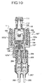
- Fig. 10 further shows another embodiment of the gas burner safety device of the present invention.
- the same numerical is given to the same structure of the abovementioned embodiment to omit explanation.
- a part of the electromagnetic valve 100" is modified from the abovementioned embodiment.
- a pipe-shaped male terminal 107" is adopted as the second connector instead of the pipe-shaped male terminal 107 shown in Fig. 2.
- a screw cap 107a" to be screwed to the gas supply conduit 1 etc, is formed at the pipe-shaped male terminal 107".
- a stepped portion 107b" for being latched with the pawl portion 206a" is formed inside the cylindrical portion to which the fit portion 206a is fitted.
- the pipe-shaped male terminal 107" serves as the screw cap 107a" to be screwed to a screw portion of a piping etc. as well as the second connector to be connected to the first connector 206 of the thermo-couple unit 200. Therefore, by screwing the screw cap 107a" to a desired position (for example, the gas supply passage) while grounding the pipe-shaped male terminal 107", the gas burner safety device can be fixed without using any separate fix member.
- the pipe-shaped male terminal 107, 107', 107" as the second connector is formed cylindrical, and the fit portion 206a to form the first connector is formed approximately cylindrical.
- the pipe-shaped male terminal and the fit portion do not have to be circular, for example, rectangular. In this case, the device can also be brought down in width and in size. Further, the pair of male terminals and the pair of female terminals can reliably be connected.
- the inner female terminal 204 and the outer female terminal 205 which constitute the pair of female terminals have the pair of spring pieces 204a, 204a, 205a, 205a, respectively.
- FIG. 11 and Fig. 12 Another embodiment is explained based on Fig. 11 and Fig. 12.
- a pin-shaped male terminal 105 and a pipe-shaped male terminal 107 (107', 107"), namely a pair of male terminals, are disposed in the electromagnetic valve unit 100, and an inner female terminal 204 and an outer female terminal 205, namely a pair of female terminals, are disposed in the thermo-couple unit 200.
- the pin-shaped male terminal 105 and the inner female terminal 204 are fitted, and the pipe-shaped male terminal 107 and the outer female terminal 205 are fitted.
- the terminals in the electromagnetic valve unit 100 are not limited to two male terminals, and the terminals in the thermo-couple unit 200 are not limited to two female terminals.
- the electromagnetic valve unit 100 and the thermo-couple unit 200 respectively have one male terminal and one female terminal.
- a first unit 300 has a pipe-shaped male terminal 301, a pair of inner female terminals 302 made of spring material at the inside of the pipe-shaped male terminal 301, and a support member 303 at the outside of the inner female terminals 302.
- the support member 303 is made of insulating material and is disposed between the pipe-shaped male terminal 301 and the inner female terminal 302.
- the pair of inner female terminals 302 is disposed to sandwich the center axis P of the cylinder of the pipe-shaped male terminal, and extend in the direction parallel to the center axis P.
- the support member 303 is cylindrical having the center axis P of the pipe-shaped male terminal 301 as its center, and has a slit 304 which is parallel to the center axis P.
- the sit 304 does not necessarily need to be formed at the support member 303.
- the top end of the inner female terminal 302 which is disposed inside the pipe-shaped male terminal 301 does not project outside than the top end of the pipe-shaped male terminal 301.
- the pipe-shaped male terminal 301 includes an arc portion of the cylinder of the pipe-shaped male terminal 301, namely a shape of a cylinder which part is deleted.
- the pipe-shaped male terminal 301 can be a cylindrical shape without any notch portion.
- the pipe-shaped male terminal 107 shown as a cylindrical shape in Fig. 1 through 4 and Fig. 9 through 10, can be a shape including an arc portion of a cylinder, namely a shape of a cylinder which part is deleted.
- a second unit 400 has a pin-shaped male terminal 401, a pair of outer female terminals 402 made of spring material extending being parallel to the pin-shaped male terminal 401, and a support member 403 made of insulating material to respectively support the outer female terminals 402.
- the pin-shaped male terminal 401 of the second unit 400 contacts to the pair of inner female terminals 302 of the first unit 300, and the pipe-shaped male terminal 301 of the first unit 300 contacts to the pair of outer female terminals 402 of the second unit 400.
- the first unit 300 and the second unit 400 respectively have a male terminal and a female terminal. Therefore, the first unit 300 and the second unit 400 are not limited to have two male terminals or two female terminals.
- the first unit 300 can be the electromagnetic valve unit 100 or the thermo-couple unit 200.
- the second unit 400 can be the thermo-couple unit 200 or the electromagnetic valve unit 100.
- the electromagnetic valve unit 100 has a pair of male terminals and the thermo-couple unit 200 has a pair of female terminals.
- the electromagnetic valve unit 100 has a pair of female terminals and the thermo-couple unit 200 has a pair of male terminals.
- the pipe-shaped male terminal 301 of the first unit can be sandwiched by and connected to the female terminal 402 of the second unit 400 at any position of the arc shape, and in the case of the cylindrical shape without any notch portion at any position of 360 degrees.
- the flexibility of the attaching angle at the time of connecting the electromagnetic valve unit 100 and the thermo-couple unit 200 is improved, and the assembling operation can be easily performed.
- two terminals in the second unit 400 can be surrounded by a connecter such as the second connecter 206.
- the gas burner safety device of the present invention downsizing in width and in size, structure simplification, cost reduction, flexibility of the attaching angle when connecting, etc. can be obtained. Therefore, not limited to a gas cooking stove, the device can be adopted to a gas water heater and other gas applications, which need a system to close the gas passage when the burning gas flame extinguishes unexpectedly.
Landscapes
- Engineering & Computer Science (AREA)
- Chemical & Material Sciences (AREA)
- Combustion & Propulsion (AREA)
- Mechanical Engineering (AREA)
- General Engineering & Computer Science (AREA)
- Magnetically Actuated Valves (AREA)
- Control Of Combustion (AREA)
- Feeding And Controlling Fuel (AREA)
- Regulation And Control Of Combustion (AREA)
Abstract
Description
- The present invention relates to a gas burner safety device which is employed to a gas cooking stove, a gas water heater, and the like. More particularly, it relates to a gas burner safety device to which a thermo-couple unit and an electromagnetic valve unit which is operated by electricity generated with thermoelectric power are integrally coupled.
- In the related art, a gas cooking stove system as shown in Fig. 13 for example is known. This system comprises a
main burner 2 disposed at the upper end of a gas supply conduit 1, a lighting burner 4 disposed at the top end of anassist supply conduit 3 which separates from the gas supply conduit 1, a gasburner safety device 8 to which anelectromagnetic valve unit 6 having avalve body 5 to open and close the passage of the gas supply conduit 1 and a thermo-couple unit 7 havingcables 7a', 7b'connected to theelectromagnetic unit 6 are integrally arranged, anoperating shaft 9, and so on, as disclosed in Japanese Patent Laid-open 2000-18591 and H8-178296. - With the system for a gas cooking stove, when the
main burner 2 is lighted by the flame of the lighting burner 4 by pushing theoperating shaft 9 and introducing the gas into the gas supply conduit 1 and theassist supply conduit 3, the flame of themain burner 2 heats the top end (a thermal sensitive portion) of the thermo-couple unit 7. Then, thermoelectric power is generated at the thermo-couple unit 7, and the electricity generated by the thermoelectric power flows in a coil of theelectromagnetic valve unit 6 to generate electromagnetic power. In this manner, thevalve body 5 is sucked and maintains the gas passage at an opened state. On the contrary, when the flame of themain burner 2 is extinguished by blow-off, boil-spill or the like, the heating to the thermo-couple unit 7 is interrupted and the thermoelectric power, namely the electromagnetic force, is extinguished. Then, thevalve body 5 is returned by a return spring and the gas passage is closed. In this manner, emission of unburned gas is prevented. - Here, as shown in Fig. 14(a) (b), the
electronic valve unit 6 and the thermo-couple unit 7 are electrically connected by connecting twomale terminals electromagnetic valve unit 6 side with twofemale terminals couple unit 7 side. Accordingly, two pairs ofmale terminals female terminals - Further, as shown in Fig. 13 through 15, the thermo-
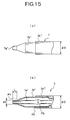
couple unit 7 comprisescables 7a', 7b'which are respectively connected to thefemale terminal conductive member 7a" as the thermal sensitive portion which is disposed at the top end of thecables 7a', 7b', a pipe-shapedconductive member 7b" which is disposed around and connected to the pole-shapedconductive member 7a" with the top end portion which is formed as a tapered cone-shape, and a pipe-shapedconductive member 7b'''which diameter is φD. A hot junction part P1 is formed at the top end portion at which the pole-shapedconductive member 7a" and the pipe-shapedconductive member 7b" are connected, and a cold junction part P2, P3 is formed at a specific distance apart from the hot junction part P1. - Here, with the abovementioned conventional gas burner safety device, in the case of adopting a connecting structure as shown in Fig. 14(a), (b), the
male terminals female terminals - Furthermore, performances, such as high thermoelectric power, quick response, etc, are needed for the thermo-
couple unit 7 to be able to precisely detect the extinguishment of the gas flame. Therefore, to achieve downsizing, cost-reduction and the like as the whole device, the performance has to be obtained without enlargement, cost-up and the like of the thermal sensitive portion (7a", 7b",7b"'). - The present invention was devised in view of the abovementioned circumstances of the related art. The object of the present invention is to provide a gas burner safety device with improved performance reliability, while achieving downsizing, cost-reduction, assembling facilitation, etc. of the device.
- A gas burner safety device of the present invention comprises a thermo-couple unit having two terminals connected to a thermal sensitive portion, and an electromagnetic valve unit having two terminals connected to a coil for magnetizing and respectively connected to the two terminals of the thermo-couple unit and a valve body driven by electromagnetic force generated by powering to the coil, and either two terminals of the thermo-couple unit or the electromagnetic valve unit comprise a pipe-shaped male terminal having at least an arc-shaped portion of a cylinder and either of an inner male terminal and an inner female terminal which is disposed inside the pipe-shaped male terminal, and the other two terminals of the thermo-couple unit or the electromagnetic valve unit comprise an outer female terminal connected to at least one side of the inside and the outside of the wall face of the pipe-shaped male terminal and the other of the inner male terminal and the inner female terminal which is disposed inside the pipe-shaped male terminal.
- With this structure, when the thermo-couple unit and the electromagnetic unit are integrally connected, the pipe-shaped male terminal which is disposed in either of the thermo-couple unit and the electromagnetic valve unit is connected to the outer female terminal which is disposed in the other of the thermo-couple unit and the electromagnetic valve unit. Either of the inner female terminal and the inner male terminal which is disposed in the axis direction at the center axis position of the pipe-shaped male terminal is connected to the other of the inner female terminal and the inner male terminal which is disposed in the unit without the pipe-shaped male terminal. In this manner, for connecting and fitting the thermo-couple unit and the electromagnetic valve unit, the terminals can be disposed in parallel to the axis direction of the pipe-shaped male terminal. Then, the device can be downsized in width and in size. Further, since the pipe-shaped male terminal can be connected to the outer female terminal at any position in the arc direction of the pipe-shaped male terminal, the attaching angle between the thermo-couple unit and the electromagnetic valve unit can be flexible when connecting.
- In the abovementioned structure, it is possible that the inner female terminal has a pair of spring pieces which can sandwich the inner male terminal, and the outer female terminal has a pair of spring pieces which can sandwich the wall face of the pipe-shaped male terminal both from the inside and the outside.
- With this structure, in the connecting state, the pin-shaped male terminal is sandwiched by the spring pieces of the inner female terminal, and the wall face of the pipe-shaped male terminal is sandwiched by the spring pieces of the outer female terminal both from the inside and outside. Therefore, reliable electrical connection can be obtained.
- In the abovementioned structure, it is possible that the inner female terminal and the outer female terminal are folded approximately in a V-shape to have a flexible piece, and the pipe-shaped male terminal and the inner male terminal are inserted and detached in the direction approximately perpendicular to the deforming direction of the flexible piece.
- With this structure, the connecting pressure between the male terminal (the pipe-shaped male terminal and the inner male terminal) and the female terminal (the inner female terminal and the outer female terminal) is exerted approximately even in the direction of inserting and detaching. Therefore, stable electrical contact can be obtained reliably.
- In the abovementioned structure, it is possible that the pipe-shaped male terminal is formed longer than the terminal disposed inside the pipe-shaped male terminal
- With this structure, since the pin-shaped male terminal does not project from the pipe-shaped male terminal and stays inside at the state that the electromagnetic valve unit and the thermo-couple unit are separated, breakage etc. of the pin-shaped male terminal can be prevented.
- In the abovementioned structure, it is possible that the thickness of the pipe-shaped male terminal is the same dimension as the outer diameter of the inner male terminal.
- With this structure, since the same part can be used for both the inner female terminal and the outer female terminal which constitute a pair of female terminals, cost-reduction of the device can be obtained due to the commonality of parts.
- In the abovementioned structure, it is possible that either the thermo-couple unit or the electromagnetic valve unit comprises the inner female terminal and the outer female terminal , and further comprises a fit portion which retains the inner female terminal and is fitted inside the pipe-shaped male terminal, and a sandwich piece which retains the outer female terminal and sandwiches the pipe-shaped male terminal from the outside in cooperation with the outer circumference of the fit portion.
- With this structure, the following occurs when the thermo-couple unit and the electromagnetic valve unit are connected. The fit portion is fitted inside the pipe-shaped male terminal, and the pin-shaped male terminal is connected to the inner female terminal which is surrounded by the fit portion. The sandwich piece sandwiches the pipe shaped male terminal in cooperation with the outer circumference of the fit portion, and the inner face and the outer face of the pipe-shaped male terminal are connected to the outer female terminal. In this manner, reliable electric connection can be obtained.
- In the abovementioned structure, it is possible that the pipe-shaped male terminal is formed with almost even thickness and the fit portion is formed approximately cylindrical to match with the pipe-shaped male terminal.
- With this structure, the pipe-shaped male terminal (the electromagnetic valve unit) which is formed cylindrical and the fit portion (the thermo-couple unit) which is formed approximately cylindrical to match with the pipe-shaped male terminal are fitted to be point symmetry around the axis. Therefore, the thermo-couple unit and the electromagnetic valve unit can be fitted in the direction of any angle without caring about the orientation, and the assembling operation can be easily performed.
- In the abovementioned structure, it is possible that the pipe-shaped male terminal has a folded portion which top end portion is folded inside, and the fit portion has a pawl portion for latching with the folded portion.
- With this structure, when the fit portion (the thermo-couple unit) is fitted to the pipe-shaped male terminal (the electromagnetic valve unit), the pawl portion of the fit portion latches the folded portion of the pipe-shaped male terminal. Accordingly, detachment of the fit portion from the pipe-shaped male terminal can be prevented.
- In the abovementioned structure, it is possible that the fit portion has a deform portion which can elastically deform in the direction perpendicular to the direction of fitting to the pipe-shaped male terminal, and the pawl portion is formed at the top end of the deform portion.
- With this structure, at the time of inserting the fit portion to the pipe-shaped male terminal, after the fit portion is inserted to a specific position with the deform portion deforming to the inside, the deform portion elastically returns and the pawl portion disposed at the top end thereof latches the folded portion of the pipe-shaped male terminal. Accordingly, the fitting operation of the fit portion (the thermo-couple unit) and the pipe-shaped male terminal (the electromagnetic valve unit) can easily be performed, and easy detachment of the fit portion from the pipe-shaped male terminal can be prevented.
- In the abovementioned structure, it is possible that the pipe-shaped male terminal integrally has an attachment flange for fixing the electromagnetic valve unit at a desired position.
- With this structure, by fixing the pipe-shaped male terminal at a specific position as an attachment flange while grounding, the gas burner safety device which comprises the electromagnetic valve unit and the thermo-couple unit can be fixed.
- In the abovementioned structure, it is possible that the pipe-shaped male terminal integrally has a screw cap for fixing the electromagnetic valve unit at a desired position.
- With this structure, by screwing the screw cap to a desired position while grounding the pipe-shaped male terminal, the gas burner safety device which comprises the electromagnetic valve unit and the thermo-couple unit can be fixed.
- In the abovementioned structure, it is possible that the electromagnetic valve unit has a movable core which is integrally movable with the valve body and a fixed core on which the coil is wound, and the pipe-shaped male terminal integrally has a holder for retaining the fixed core.
- With this structure, since the pipe-shaped male terminal serves as a holder to retain the fixed core as well as the second connector, the parts count can be reduced and the structure can be simplified.
- Further, a gas burner safety device of the present invention comprises a thermo-couple unit having a thermal sensitive portion at the top end thereof, and an electromagnetic valve unit which is driven by electromagnetic force based on thermoelectric power generated at the thermo-couple unit, and the thermal sensitive portion of the thermo-couple unit includes a pole-shaped conductive member and a pipe-shaped conductive member which is cylindrically disposed around and connected to the pole-shaped conductive member with the top end portion which is formed as a cone shape, and the pipe-shaped conductive member is formed so that the thickness at a cold junction part of the rear end side is larger than that at a hot junction part of the top end to which the pole-shaped conductive member is connected.
- With this structure, the cold junction side of the pipe-shaped conductive member is thickly formed. Therefore, even though the diameter is smaller than that of the related art, the same thermoelectric power characteristics and response can be maintained. If the diameter is kept as the related art, the thermoelectric power characteristics and response can be improved.
- In the abovementioned structure, it is possible that a top end thin portion which outer diameter is the smallest is formed at the top end connecting region of the pole-shaped conductive member and the pipe-shaped conductive member, and the length of the top end thin portion is formed at about 30 through 50 percent of the distance from the hot junction part to the cold junction part.
- With this structure, by setting the top end thin portion longer than the related art, the thermoelectric power characteristics and response can be improved (namely obtaining higher thermoelectric power and quicker response).
- As mentioned above, with the gas burner safety device of the present invention, the two terminals at the electromagnetic valve unit side and the two terminals at the thermo-couple unit side are disposed in the same axis direction. Therefore, the device can be aggregated and the device can be brought down in width and in size. Further, in the unit having the pipe-shaped male terminal, by disposing the other terminal is at the center axis position of the pipe-shaped male terminal, the pipe-shaped male terminal can be fitted and connected to the outer female terminal of the other unit at any angle having the center axis as the center. In this manner, flexibility of the attaching angle between the thermo-couple unit and the electromagnetic valve unit at the time of connecting can be improved, and assembling operation can easily be performed.
- Further, at the thermal sensitive portion of the thermo-couple unit, a pipe-shaped conductive member which is cylindrically disposed around and connected to the pole-shaped conductive member with the top end portion which is formed as a cone shape is formed so that the thickness at a cold junction part of the rear end side is larger than that at the hot junction part to which the pole-shaped conductive member is connected. Therefore, even though the diameter is smaller than that of the related art, the same thermoelectric power characteristics and response can be maintained. If the diameter is kept as the related art, the thermoelectric power characteristics and response can be improved.
-
- Fig. 1 shows an embodiment of a gas burner safety device of the present invention; (a) is a front view of the device and (b) is a side view of the device.
- Fig. 2 is a sectional view of the device shown in Fig.1 in the fitting direction (the axis direction).
- Fig. 3 is a sectional view showing the state that an electromagnetic valve unit and a thermo-couple unit which constitute the device shown in Fig. 1 are separated.
- Fig. 4 (a) is a sectional view at E1-E1 in Fig.2. Fig. 4 (b) is a sectional view at E2-E2 in Fig. 2.
- Fig. 5 is a sectional view showing a part of the first connector of the thermo-couple unit.
- Fig. 6 shows the relation between an inner female terminal of the thermo-couple unit and a pin-shaped male terminal of the electromagnetic valve unit; (a) is a side view, (b) is a front view, (c) is an enlarged front view of one part, and (d) is a sectional view at E3-E3 in Fig.6 (c).
- Fig. 7 shows a thermal sensitive portion of the thermo-couple unit; (a) is an outline drawing and (b) is a sectional view.
- Fig. 8 shows another embodiment of the thermal sensitive portion of the thermo-couple unit; (a) is an outline drawing and (b) is a sectional view.
- Fig. 9 is a sectional view showing another embodiment of the gas burner safety device of the present invention.
- Fig. 10 is a sectional view further showing another embodiment of the gas burner safety device of the present invention.
- Fig. 11 is a perspective view showing another embodiment of the gas burner safety device of the present invention.
- Fig. 12 is a sectional view of the gas burner safety device shown in Fig. 11.
- Fig. 13 is a system diagram showing a system of a gas cooking stove to which a conventional gas burner safety device is adopted.
- Fig. 14 shows a conventional gas burner safety device; (a) is a sectional view of the device and (b) is an end face view of the device.
- Fig. 15 shows a thermal sensitive portion of a thermo-couple unit which constitutes a part of the conventional gas burner safety device; (a) is an outline drawing and (b) is a sectional view.
- The preferred embodiments of the present invention are explained in the following with reference to the attached drawings.
- Fig. 1 through 7 show an embodiment of a gas burner safety device of the present invention. Fig. 1 shows a front view and a side view of the whole device. Fig. 2 is a sectional view of the device in the axis direction. Fig. 3 is a sectional view showing the state that an electromagnetic valve unit and a thermo-couple unit are separated. Fig. 4 is sectional view of the device in the direction perpendicular to the axis of the device. Fig. 5 is a sectional view showing a part of the device. Fig. 6 is a partial view showing the structure of the terminals. Fig. 7 has a side view and a sectional view showing a thermal sensitive portion of the thermo-couple unit.
- As shown in Fig. 1 through 3, in this device, the
electromagnetic valve unit 100 and the thermo-couple unit 200 are coupling freely to be attached and detached. - As shown in Fig. 1 through 3, the
electromagnetic valve unit 100 comprises a fixedcore 101, a resin-madebobbin 102 to support the fixedcore 101, acoil 103 for magnetization which integrally wounds on the fixedcore 101 and thebobbin 102, aconductive holder 104 to fix thebobbin 102 by calking, a pin-shapedmale terminal 105 which is connected to oneend 103a of thecoil 103 and constitutes one portion of a pair of male terminals, an insulatemember 106 to retain the pin-shapedmale terminal 105 at the center of theholder 104 while performing electrical insulation therebetween, a pipe-shapedmale terminal 107 made of conductive material which is connected to theholder 104 and constitutes the other portion of the pair of male terminals, a resin-madecase 108 to cover the fixedcore 101, amovable core 110 fixed at one end of ashaft 109 which is slidably supported by thecase 108, a rubber-madevalve body 111 fixed at the other end of theshaft 109, aspring 112 to urge thevalve body 111 outward, and so on. - The fixed
core 101 is made of magnetic material, such as permalloy, and is formed approximately into a U-shape. Thebobbin 102 is made of isolating material (non-conductive material), and is formed approximately into an inverted U-shape. At the state that the fixedcore 101 is supported by thebobbin 102, thebobbin 102 and the fixedcore 101 are formed approximately into an H-shape, and thecoil 103 is wound thereon as the longitudinal winding. - The
holder 104 is made of conductive material, such as brass, and the top end portion thereof is calked to fix thebobbin 102. Theother end 103b of thecoil 103 is electrically connected to the top end of theholder 104 by hot welding, cold welding, and so on. - The pin-shaped
male terminal 105 is made of conductive material, and formed as a tapered cylindrical shape (a needle shape) which top end is closed. Then, it is retained at the center of theholder 104 without any contact thereto by the isolatemember 106. - The pipe-shaped
male terminal 107 is made of conductive material, such as a metal plate which is of a specific thickness, and is formed cylindrical having an approximatelyrhomboid attachment flange 107a integrally at the top end. Further, a foldedportion 107b is formed by folding the end edge portion inside. Then, the pipe-shaped male terminal 107 functions as the second connector which is fitted to (the below-mentionedfirst connector 206 of) the thermo-couple unit 200. - The relation between the pipe-shaped
male terminal 107 and the pin-shapedmale terminal 105 is shown in Fig. 3. The pin-shapedmale terminal 105 is disposed at the inside center of the pipe-shapedmale terminal 107. The pipe-shapedmale terminal 107 is formed to be longer than the pin-shaped male terminal by dimension L, so that the pin-shapedmale terminal 105 does not project from the pipe-shapedmale terminal 107. - With this structure, when the
electromagnetic valve unit 100 is handled by itself, the pin-shaped male terminal does not directly contact anything, even if it drops or hits other parts. Therefore, bending, breakage and the like can be prevented. - Here, the pipe-shaped
male terminal 107 is formed so that the thickness including the foldedportion 107b is the same as the diameter of the pin-shapedmale terminal 105. With this structure, the same parts can be used for both an innerfemale terminal 204 and an outerfemale terminal 205, which is described later. - As shown in Fig. 1 through 4, the thermo-
couple unit 200. comprises a thermalsensitive portion 201 formed at the top end, afirst cable 202 and asecond cable 203 which are drawn from the thermalsensitive portion 201, the innerfemale terminal 204 which is connected to an end portion of thefirst cable 202 and constitutes one portion of a pair of female terminals, the outerfemale terminal 205 which is connected to an end portion of thesecond cable 203 and constitutes the other portion of the pair of female terminals, thefirst connector 206 to retain the inner female terminal and the outerfemale terminal 205, aseal member 207 to seal an end portion of thefirst connector 206, and so on. - Here, since the same part can be used for both the inner
female terminal 204 and the outerfemale terminal 205, cost-reduction of the device can be obtained due to the commonality of parts. - As shown in Fig. 1 and Fig. 7 (a) (b), the thermal
sensitive portion 201 comprises a pole-shapedconductive member 201a which is connected to thefirst cable 202, a pipe-shapedconductive member 201b which is disposed cylindrically around the pole-shapedconductive member 201a and connected to the pole-shapedconductive member 201a at the top end which is formed conical, a second pipe-shapedconductive member 201c which connects the pipe-shapedconductive member 201b to thefirst cable 203, and so on. - The pole-shaped
conductive member 201a is made of alloy material of Ni, Cu and Mn, and forms a solid shape. The pipe-shapedconductive member 201b is made of alloy material of Ni, Cr and Fe, and the top end is formed conical and the bottom end is formed cylindrical. Here, the thickness at the conical region is thinner than that at the cylindrical region. Further, the outer diameter at the cylindrical region of the pipe-shapedconductive member 201b is smaller than that of the related art shown in Fig. 13. Furthermore, the second pipe-shapedconductive member 201c is formed cylindrical with a diameter φ Dl which is smaller than the diameter of the related art in Fig. 13 (φD1<φD). - Then, as shown in Fig. 7 (b), a hot junction part P1 is formed at the top end region at which the pole-shaped
conductive member 201a and the pipe-shapedconductive member 201b are connected, and a cold junction part P2, P3 is formed at a position which is apart from the hot junction part P1 toward the rear by a specific distance. - Here, the rear side of the pipe-shaped
conductive member 201b, namely the cold junction part P2, is formed thicker than the warm junction P1. Therefore, even though the diameter of the pipe-shapedconductive member 201b is smaller than that of the related art, the same thermoelectric power characteristics and response can be maintained. In this manner, downsizing and cost-reduction can be achieved. - Further, at the connecting region of the pole-shaped
conductive member 201a and the pipe-shapedconductive member 201b, the top end thin portion which outer diameter φ d is the smallest is defined. The length L1 of the top end thin portion is formed at about 30 through 50 percent of the distance between the hot junction part P1 and the cold junction part P2. The dimension L1 is set to be longer than the dimension L of the related art shown in Fig. 13, and contributes to high thermoelectric power and quick response. - Here, as shown in Fig. 8 (a) (b), it is possible to adopt the pipe-shaped
conductive member 201b' with the same diameter as the related art shown in Fig. 13, the second pipe-shapedconductive member 201c' with the same diameter φ D as the related art, and the top end thin portion with the same diameter φ d and the length L as the related art as another thermal sensitive portion 201', and to form the rear side of the pipe-shapedconductive member 201b', namely the cold junction part P2, thicker than the warm junction P1. In this case, with the same size as the related art, the thermoelectric power characteristics and response improve further. - As shown in Fig. 3, Fig. 4 and Fig. 6 (a) (b) (c) (d), the inner
female terminal 204 has a pair ofspring pieces male terminal 105 along the axis from both outer sides in the diameter direction of the circumference face. As shown in Fig. 6 (d), the pair ofspring pieces flexible pieces 204a', 204a' which can contact both sides of the circumference face of the pin-shapedmale terminal 105 while facing each other. - Then, the pin-shaped
male terminal 105 is free to be inserted and detached in the direction (the direction being perpendicular to the paper face of Fig.4 (a), (b)) which is approximately perpendicular to the deforming direction (the direction being horizontal to Fig. 4 (a), (b)) of the pair offlexible pieces 204a', 204a'. - With this structure, since the contact pressure between the pin-shaped
male terminal 105 and the innerfemale terminal 204 acts approximately even in the insert and detach direction, the electrical contact can properly be obtained at a stable condition. - The outer
female terminal 205 is formed as approximately the same shape as the innerfemale terminal 204. As shown in Fig. 3 and Fig. 4, the outerfemale terminal 205 has a pair ofspring pieces spring pieces flexible pieces 205a', 205a' which can contact to both sides of the inner circumference and the outer circumference of the pipe-shapedmale terminal 107 as facing each other. - Then, the pipe-shaped
male terminal 107 is free to be inserted and detached in the direction (the direction being perpendicular to the paper face of Fig.4 (a), (b)) which is approximately perpendicular to the deforming direction (the direction being horizontal to Fig. 4 (a), (b)) of the pair offlexible pieces 204a', 204a'. - With this structure, since the contact pressure between the pipe-shaped
male terminal 107 and the outerfemale terminal 205 acts approximately even in the insert and detach direction, the electrical contact can properly be obtained at a stable condition. - As shown in Fig. 3 and Fig. 4, the
first connector 206 comprises afit portion 206a which is fitted to the inside of the pipe-shapedmale terminal 107 to retain the innerfemale terminal 204, asandwich piece 206b which retains the outerfemale terminal 205 in cooperation with the outer circumference of thefit portion 206a and which sandwiches the pipe-shaped male terminal 107 from the outside, and so on. - Further, the
fit portion 206 is formed to include adeform portion 206a' which can elastically deform in the direction perpendicular to the fitting direction by forming an incision in the fitting direction at a part thereof. Then, as shown in Fig. 5, apawl portion 206a" is integrally formed at the top end of thedeform portion 206a' to latch with the foldedportion 107b of the pipe-shapedmale terminal 107. - In this construction, at the time of fitting the
fit portion 206a to the pipe-shapedmale terminal 107, after thefit portion 206a' is fitted to a specific position with thedeform portion 206a' deforming to the inside, thedeform portion 206a' elastically returns and thepawl portion 206a" disposed at the top end thereof is latched with the foldedportion 107b of the pipe-shapedmale terminal 107. Accordingly, the fitting operation of thefit portion 206a (the first connector 206) and the pipe-shaped male terminal (the second connector) 107 can easily be performed, and the unexpected detaching of thefit portion 206a from the pipe-shapedmale terminal 107 can reliably be prevented. - In the abovementioned structure, the
fit portion 206a' is formed approximately cylindrical being integral with thedeform portion 206a', so as to match with the pipe-shapedmale terminal 107 as the second connector which shape is cylindrical. Accordingly, when thefirst connector 206 and the second connector (the pipe-shaped male terminal) 107 are fitted together, thefit portion 206a is fitted to the inside of the pipe-shapedmale terminal 107. The pin-shapedmale terminal 105 is fitted into and connected to the innerfemale terminal 204 which is surrounded by thefit portion 206a. Thesandwich piece 206b sandwiches the pipe-shapedmale terminal 107 in cooperation with the outer circumference of thefit portion 206a. Then, the pipe-shapedmale terminal 107 is fitted into and connected to the outerfemale terminal 205 with which the inside face and the outside face of the pipe-shapedmale terminal 107 contact. In this manner, the electrical contact can reliably be obtained. - In addition, since the pipe-shaped male terminal (the second connector) 107 and the
fit portion 206a (the first connector 206) are fitted to be point symmetry around the axis, thefirst connector 206 and the second connector (the pipe-shaped male terminal) 107 can be fitted in the direction at any angle without caring the orientation. Therefore, the assembling operation can easily be performed. - The assembling process of the
electromagnetic valve unit 100 and the thermo-couple unit 200 having the abovementioned structure is shown in Fig. 3. The pin-shapedmale terminal 105 is positioned to face the innerfemale terminal 204, and both are brought close to each other. Thefit portion 206a (and thedeform portion 206a') of thefirst connector 206 is inserted to the pipe-shaped male terminal (the second connector) 107. After the fitting is performed with thedeform portion 206a' deforming to the center side, thepawl portion 206a" is latched with the foldedportion 107b. In this manner, theelectromagnetic valve unit 100 and the thermo-couple unit 200 are reliably connected. - Further, at the same time of this fitting operation, the pin-shaped
male terminal 105 is inserted to the innerfemale terminal 204 and is sandwiched by the pair ofspring pieces male terminal 107 is inserted to the outerfemale terminal 205, and sandwiched by the pair ofspring pieces female terminal 204 and the outer female terminal 205) are electrically connected reliably. - Next, the operation when this gas burner safety device is utilized to a gas cooking stove system as shown in Fig. 11 is explained. First, an operating
shaft 9 is pushed to introduce gas to a gas supply conduit 1 and anassist supply conduit 3, and amain burner 2 is lighted with a flame of a lighting burner 4. Then, the flame of the main burner heats the thermalsensitive portion 201 of the thermo-couple unit 200. - With this heating, thermoelectric power is generated at the thermo-
couple unit 200. The electricity generated by the thermoelectric power flows in acoil 103 via thefirst cable 202 and thesecond cable 203, and the electromagnetic power is generated. Then, with this electromagnetic power, amovable core 110 is sucked to a fixedcore 101, and the state that avalve body 111 keeps the gas passage opened is maintained. - On the contrary, when the flame of the
main burner 2 is extinguished by blow-off, boil-spill or the like, the heating to the thermo-couple unit 200 is interrupted and the thermoelectric power, namely the electromagnetic force, is extinguished. Then, thevalve body 111 is returned by areturn spring 112 and the gas passage is closed. In this manner, emission of unburned gas is prevented. - Fig. 9 shows another embodiment of the gas burner safety device of the present invention. The same numerical is given to the same structure of the abovementioned embodiment to omit explanation.
- As shown in Fig. 9, in this device, a part of the electromagnetic valve unit 100' is modified from the abovementioned embodiment. A pipe-shaped male terminal 107' is adopted as the second connector instead of the pipe-shaped
male terminal 107 and theholder 104 shown in Fig. 2. - Specifically, a
holder 107a' to retain the fixedcore 101 and abobbin 102 is integrally formed at the pipe-shaped male terminal 107'. A steppedportion 107b' for being latched with thepawl portion 206a" is formed at the inside of the cylindrical portion to which thefit portion 206a is fitted. - In this device, since the pipe-shaped male terminal 107' serves as the holder to retain the fixed
core 101 as well as the second connector to be connected to thefirst connector 206 of the thermo-couple unit 200, the parts count can be reduced accordingly. Therefore, the device can be simplified in structure and can be downsized. - Fig. 10 further shows another embodiment of the gas burner safety device of the present invention. The same numerical is given to the same structure of the abovementioned embodiment to omit explanation.
- As shown in Fig. 10, in this device, a part of the
electromagnetic valve 100" is modified from the abovementioned embodiment. A pipe-shapedmale terminal 107" is adopted as the second connector instead of the pipe-shapedmale terminal 107 shown in Fig. 2. - Specifically, a
screw cap 107a" to be screwed to the gas supply conduit 1 etc, is formed at the pipe-shapedmale terminal 107". A steppedportion 107b" for being latched with thepawl portion 206a" is formed inside the cylindrical portion to which thefit portion 206a is fitted. - In this device, the pipe-shaped
male terminal 107" serves as thescrew cap 107a" to be screwed to a screw portion of a piping etc. as well as the second connector to be connected to thefirst connector 206 of the thermo-couple unit 200. Therefore, by screwing thescrew cap 107a" to a desired position (for example, the gas supply passage) while grounding the pipe-shapedmale terminal 107", the gas burner safety device can be fixed without using any separate fix member. - In the abovementioned embodiment, the pipe-shaped
male terminal fit portion 206a to form the first connector is formed approximately cylindrical. However, not limited to this structure, the pipe-shaped male terminal and the fit portion do not have to be circular, for example, rectangular. In this case, the device can also be brought down in width and in size. Further, the pair of male terminals and the pair of female terminals can reliably be connected. - In the abovementioned embodiment, the inner
female terminal 204 and the outerfemale terminal 205 which constitute the pair of female terminals have the pair ofspring pieces - Another embodiment is explained based on Fig. 11 and Fig. 12. With the embodiment shown in Fig. 1 through 4 and Fig. 9 through 10, a pin-shaped
male terminal 105 and a pipe-shaped male terminal 107 (107', 107"), namely a pair of male terminals, are disposed in theelectromagnetic valve unit 100, and an innerfemale terminal 204 and an outerfemale terminal 205, namely a pair of female terminals, are disposed in the thermo-couple unit 200. Then, the pin-shapedmale terminal 105 and the innerfemale terminal 204 are fitted, and the pipe-shapedmale terminal 107 and the outerfemale terminal 205 are fitted. With the embodiment shown in Fig. 11 and Fig. 12, the terminals in theelectromagnetic valve unit 100 are not limited to two male terminals, and the terminals in the thermo-couple unit 200 are not limited to two female terminals. Here, theelectromagnetic valve unit 100 and the thermo-couple unit 200 respectively have one male terminal and one female terminal. - A
first unit 300 has a pipe-shapedmale terminal 301, a pair of innerfemale terminals 302 made of spring material at the inside of the pipe-shapedmale terminal 301, and asupport member 303 at the outside of the innerfemale terminals 302. Thesupport member 303 is made of insulating material and is disposed between the pipe-shapedmale terminal 301 and the innerfemale terminal 302. The pair of innerfemale terminals 302 is disposed to sandwich the center axis P of the cylinder of the pipe-shaped male terminal, and extend in the direction parallel to the center axis P. Thesupport member 303 is cylindrical having the center axis P of the pipe-shapedmale terminal 301 as its center, and has aslit 304 which is parallel to the center axis P. However, thesit 304 does not necessarily need to be formed at thesupport member 303. The top end of the innerfemale terminal 302 which is disposed inside the pipe-shapedmale terminal 301 does not project outside than the top end of the pipe-shapedmale terminal 301. In Fig. 11, the pipe-shapedmale terminal 301 includes an arc portion of the cylinder of the pipe-shapedmale terminal 301, namely a shape of a cylinder which part is deleted. However, the pipe-shapedmale terminal 301 can be a cylindrical shape without any notch portion. In addition, the pipe-shapedmale terminal 107, shown as a cylindrical shape in Fig. 1 through 4 and Fig. 9 through 10, can be a shape including an arc portion of a cylinder, namely a shape of a cylinder which part is deleted. - A
second unit 400 has a pin-shapedmale terminal 401, a pair of outerfemale terminals 402 made of spring material extending being parallel to the pin-shapedmale terminal 401, and asupport member 403 made of insulating material to respectively support the outerfemale terminals 402. As shown in Fig. 12, in the state that thefirst unit 300 and thesecond unit 400 are fitted together, the pin-shapedmale terminal 401 of thesecond unit 400 contacts to the pair of innerfemale terminals 302 of thefirst unit 300, and the pipe-shapedmale terminal 301 of thefirst unit 300 contacts to the pair of outerfemale terminals 402 of thesecond unit 400. Consequently, when connecting thefirst unit 300 and thesecond unit 400 by fitting and connecting the pin-shapedmale terminal 401 to the innerfemale terminal 302, the pipe-shapedmale terminal 301 of thefirst unit 300 is fitted and connected to thefemale terminal 402 of thesecond unit 400 at any position of the arc shape, and in the case of the cylindrical shape without any notch portion at any position of 360 degrees. - As explained above, the
first unit 300 and thesecond unit 400 respectively have a male terminal and a female terminal. Therefore, thefirst unit 300 and thesecond unit 400 are not limited to have two male terminals or two female terminals. Thefirst unit 300 can be theelectromagnetic valve unit 100 or the thermo-couple unit 200. Thesecond unit 400 can be the thermo-couple unit 200 or theelectromagnetic valve unit 100. Further, in Fig. 1 through 4, theelectromagnetic valve unit 100 has a pair of male terminals and the thermo-couple unit 200 has a pair of female terminals. However, on the contrary, it is possible that theelectromagnetic valve unit 100 has a pair of female terminals and the thermo-couple unit 200 has a pair of male terminals. - With the embodiment shown in Fig. 11 and Fig. 12, when the pin-shaped
male terminal 401 of thesecond unit 400 is fitted and connected to the innerfemale terminal 302 of thefirst unit 300, the pipe-shapedmale terminal 301 of the first unit can be sandwiched by and connected to thefemale terminal 402 of thesecond unit 400 at any position of the arc shape, and in the case of the cylindrical shape without any notch portion at any position of 360 degrees. As a result, the flexibility of the attaching angle at the time of connecting theelectromagnetic valve unit 100 and the thermo-couple unit 200 is improved, and the assembling operation can be easily performed. Here, as shown in Fig. 1 through 4, two terminals in thesecond unit 400 can be surrounded by a connecter such as thesecond connecter 206. - As mentioned above, with the gas burner safety device of the present invention, downsizing in width and in size, structure simplification, cost reduction, flexibility of the attaching angle when connecting, etc. can be obtained. Therefore, not limited to a gas cooking stove, the device can be adopted to a gas water heater and other gas applications, which need a system to close the gas passage when the burning gas flame extinguishes unexpectedly.
Claims (14)
- A gas burner safety device, comprising:a thermo-couple unit having two terminals connected to a thermal sensitive portion; andan electromagnetic valve unit having two terminals connected to a coil for magnetizing and respectively connected to said two terminals of said thermo-couple unit, and a valve body driven by electromagnetic force generated by powering to said coil;wherein either two terminals of said thermo-couple unit or said electromagnetic valve unit comprise a pipe-shaped male terminal having at least an arc-shaped portion of a cylinder, and either of an inner male terminal and an inner female terminal which is disposed inside said pipe-shaped male terminal; andwherein the other two terminals of said thermo-couple unit or said electromagnetic valve unit comprise an outer female terminal connected to at least one side of the inside and the outside of the wall face of said pipe-shaped male terminal, and the other of said inner male terminal and said inner female terminal which is disposed inside said pipe-shaped male terminal.
- The gas burner safety device according to claim 1, wherein said inner female terminal has a pair of spring pieces which can sandwich said inner male terminal, and said outer female terminal has a pair of spring pieces which can sandwich the wall face of said pipe-shaped male terminal both from the inside and the outside.
- The gas burner safety device according to claim 2, wherein said inner female terminal and said outer female terminal are folded approximately in a V-shape to have a flexible piece, and said pipe-shaped male terminal and said inner male terminal are inserted and detached in the direction approximately perpendicular to the deforming direction of said flexible piece.
- The gas burner safety device according to claim 1, wherein said pipe-shaped male terminal is formed longer than the terminal disposed inside said pipe-shaped male terminal.
- The gas burner safety device according to claim 1, wherein the thickness of said pipe-shaped male terminal is the same dimension as the outer diameter of said inner male terminal.
- The`gas burner safety device according to claim 1, wherein either said thermo-couple unit or said electromagnetic valve unit comprises said inner female terminal and said outer female terminal , and further comprises a fit portion which retains said inner female terminal and is fitted inside said pipe-shaped male terminal, and a sandwich piece which retains said outer female terminal and sandwiches said pipe-shaped male terminal from the outside in cooperation with the outer circumference of said-fit portion.
- The gas burner safety device according to claim 6, wherein said pipe-shaped male terminal is formed with almost even thickness and said fit portion is formed approximately cylindrical to match with said pipe-shaped male terminal.
- The gas burner safety device according to claim 6, wherein said pipe-shaped male terminal has a folded portion which top end portion is folded inside, and said fit portion has a pawl portion for latching with said folded portion.
- The gas burner safety device according to claim 8, wherein said fit portion has a deform portion which can elastically deform in the direction perpendicular to the direction of fitting to said pipe-shaped male terminal, and said pawl portion is formed at the top end of said deform portion.
- The gas burner safety device according to claim 1, wherein said pipe-shaped male terminal integrally has an attachment flange for fixing said electromagnetic valve unit at a desired position.
- The gas burner safety device according to claims 1, wherein said pipe-shaped male terminal integrally has a screw cap for fixing said electromagnetic valve unit at a desired position.
- The gas burner safety device according to claim 1, wherein said electromagnetic valve unit has a movable core which is integrally movable with said valve body and a fixed core on which said coil is wound, and said pipe-shaped male terminal integrally has a holder for retaining said fixed core.
- A gas burner safety device, comprising:a thermo-couple unit having a thermal sensitive portion at the top end thereof; andan electromagnetic valve unit which is driven by electromagnetic force based on thermoelectric power generated at said thermo-couple unit;wherein said thermal sensitive portion of said thermo-couple unit includes a pole-shaped conductive member, and a pipe-shaped conductive member which is cylindrically disposed around and connected to said pole-shaped conductive member with the top end portion which is formed as a cone shape; andwherein said pipe-shaped conductive member is formed so that the thickness at a cold junction part of the rear end side is larger than that at a hot junction part of the top end to which said pole shaped conductive member is connected.
- The gas burner safety device according to claim 13, wherein a top end thin portion which outer diameter is the smallest is formed at the top end connecting region of said pole-shaped conductive member and said pipe-shaped conductive member, and the length of said top end thin portion is formed at about 30 through 50 percent of the distance from said hot junction part to said cold junction part.
Applications Claiming Priority (2)
| Application Number | Priority Date | Filing Date | Title |
|---|---|---|---|
| JP2003339063 | 2003-09-30 | ||
| PCT/JP2004/014223 WO2005031213A1 (en) | 2003-09-30 | 2004-09-29 | Pilot safety shut off device for gas |
Publications (3)
| Publication Number | Publication Date |
|---|---|
| EP1669673A1 true EP1669673A1 (en) | 2006-06-14 |
| EP1669673A4 EP1669673A4 (en) | 2012-02-01 |
| EP1669673B1 EP1669673B1 (en) | 2016-06-22 |
Family
ID=34386177
Family Applications (1)
| Application Number | Title | Priority Date | Filing Date |
|---|---|---|---|
| EP04788290.7A Expired - Lifetime EP1669673B1 (en) | 2003-09-30 | 2004-09-29 | Safety shut off device for gas burner |
Country Status (5)
| Country | Link |
|---|---|
| EP (1) | EP1669673B1 (en) |
| JP (1) | JP4198156B2 (en) |
| CN (1) | CN100526718C (en) |
| BR (1) | BRPI0414923A (en) |
| WO (1) | WO2005031213A1 (en) |
Cited By (4)
| Publication number | Priority date | Publication date | Assignee | Title |
|---|---|---|---|---|
| AT509486A4 (en) * | 2009-12-18 | 2011-09-15 | Fronius Int Gmbh | BURNER AND METHOD FOR POWER GENERATION AND COMPONENT FOR SUCH A BURNER |
| ITTO20110736A1 (en) * | 2011-08-05 | 2013-02-06 | Illinois Tool Works | METHOD OF MANUFACTURING A THERMOCOUPLE FOR A COOKING AND THERMOCOUPLE PLAN SO IT IS OBTAINED |
| WO2016162173A1 (en) * | 2015-04-08 | 2016-10-13 | Orkli, S.Coop. | Safety valve adapted to a gas combustion appliance |
| WO2020135985A1 (en) * | 2018-12-24 | 2020-07-02 | Arcelik Anonim Sirketi | A cooking device comprising a safety member |
Families Citing this family (9)
| Publication number | Priority date | Publication date | Assignee | Title |
|---|---|---|---|---|
| JP4519026B2 (en) * | 2005-07-26 | 2010-08-04 | リンナイ株式会社 | Electromagnetic safety valve |
| EP2589117B1 (en) * | 2010-06-30 | 2017-11-08 | SABAF S.p.A. | Electrical connection for connecting a thermocouple to the magnet assembly of a safety cock for gas supply" |
| ES2394611B1 (en) * | 2010-07-09 | 2013-11-28 | Orkli, S.Coop. | COUPLING TO CONNECT A THERMOPAR TO AN ELECTROMAGNETIC VALVE ADAPTED TO A GAS DEVICE. |
| JP2012079452A (en) * | 2010-09-30 | 2012-04-19 | Yamatake Corp | Electronic apparatus holding socket and flame sensor |
| CN105004442A (en) * | 2015-05-11 | 2015-10-28 | 奥可利电子(昆山)有限公司 | Thermocouple connection plastic part |
| CN107437461B (en) * | 2016-05-25 | 2018-09-18 | 四川艾德瑞电气有限公司 | Liquid immersion type phase-shifting transformer phase shifting angle quick switching device |
| JP7299718B2 (en) * | 2019-03-11 | 2023-06-28 | 株式会社ミクニ | Electromagnetic actuator and blackout safety device |
| CN116136270A (en) * | 2021-11-18 | 2023-05-19 | 浙江三花智能控制股份有限公司 | Valve assembly and solenoid valve for gas cooker |
| JP7861309B2 (en) * | 2022-09-30 | 2026-05-19 | 東芝ライテック株式会社 | battery device |
Family Cites Families (10)
| Publication number | Priority date | Publication date | Assignee | Title |
|---|---|---|---|---|
| JPS6245552U (en) * | 1985-09-09 | 1987-03-19 | ||
| JPH0414866Y2 (en) * | 1987-08-26 | 1992-04-03 | ||
| JPH01139917A (en) * | 1987-11-26 | 1989-06-01 | Matsushita Electric Ind Co Ltd | Thermocouple device for gas combustion equipment |
| JP2579095Y2 (en) * | 1992-07-14 | 1998-08-20 | パロマ工業株式会社 | thermocouple |
| ES2079995B1 (en) * | 1993-01-12 | 1997-02-01 | Orkli S Coop Ltda | PERFECTED THERMOCOUPLE FOR GAS BURNER APPLIANCES. |
| ES1024395Y (en) * | 1993-03-31 | 1994-05-01 | Orkli S Coop Ltda | COAXIAL COUPLING OF THERMOCOUPLE TO THE MAGNETIC GROUP THAT CONTROLS THE PASSAGE OF GAS IN BURNERS. |
| ES1030940Y (en) * | 1995-04-27 | 1996-08-01 | Vicent Manuel Valls | CONNECTOR FOR THE THERMOCOUPLE OF A GAS BURNER. |
| JPH09184779A (en) * | 1995-12-28 | 1997-07-15 | Matsushita Electric Works Ltd | Pressure sensor |
| JP3871237B2 (en) * | 1998-07-03 | 2007-01-24 | 株式会社ミクニ | Gas appliance safety device |
| JP2000260521A (en) * | 1999-03-09 | 2000-09-22 | Yazaki Corp | connector |
-
2004
- 2004-09-29 EP EP04788290.7A patent/EP1669673B1/en not_active Expired - Lifetime
- 2004-09-29 WO PCT/JP2004/014223 patent/WO2005031213A1/en not_active Ceased
- 2004-09-29 BR BRPI0414923-8A patent/BRPI0414923A/en not_active IP Right Cessation
- 2004-09-29 CN CNB2004800280242A patent/CN100526718C/en not_active Expired - Fee Related
- 2004-09-29 JP JP2005514245A patent/JP4198156B2/en not_active Expired - Fee Related
Cited By (8)
| Publication number | Priority date | Publication date | Assignee | Title |
|---|---|---|---|---|
| AT509486A4 (en) * | 2009-12-18 | 2011-09-15 | Fronius Int Gmbh | BURNER AND METHOD FOR POWER GENERATION AND COMPONENT FOR SUCH A BURNER |
| AT509486B1 (en) * | 2009-12-18 | 2011-09-15 | Fronius Int Gmbh | BURNER AND METHOD FOR POWER GENERATION AND COMPONENT FOR SUCH A BURNER |
| ITTO20110736A1 (en) * | 2011-08-05 | 2013-02-06 | Illinois Tool Works | METHOD OF MANUFACTURING A THERMOCOUPLE FOR A COOKING AND THERMOCOUPLE PLAN SO IT IS OBTAINED |
| WO2013021341A3 (en) * | 2011-08-05 | 2013-04-11 | Illinois Tool Works Inc. | Manufacturing method for a cooking range thermocouple and thermocouple obtained therewith |
| WO2016162173A1 (en) * | 2015-04-08 | 2016-10-13 | Orkli, S.Coop. | Safety valve adapted to a gas combustion appliance |
| US10495308B2 (en) | 2015-04-08 | 2019-12-03 | Orkli, S. Coop. | Safety valve |
| RU2710638C2 (en) * | 2015-04-08 | 2019-12-30 | Оркли, С.Кооп. | Safety valve for gas combustion device |
| WO2020135985A1 (en) * | 2018-12-24 | 2020-07-02 | Arcelik Anonim Sirketi | A cooking device comprising a safety member |
Also Published As
| Publication number | Publication date |
|---|---|
| CN1860332A (en) | 2006-11-08 |
| JPWO2005031213A1 (en) | 2008-06-12 |
| JP4198156B2 (en) | 2008-12-17 |
| CN100526718C (en) | 2009-08-12 |
| BRPI0414923A (en) | 2006-11-07 |
| WO2005031213A1 (en) | 2005-04-07 |
| EP1669673B1 (en) | 2016-06-22 |
| EP1669673A4 (en) | 2012-02-01 |
Similar Documents
| Publication | Publication Date | Title |
|---|---|---|
| EP1669673B1 (en) | Safety shut off device for gas burner | |
| JP2008020176A (en) | Sensor built-in glow plug | |
| US5462431A (en) | Ignitor with metering orifice insert | |
| US6753624B2 (en) | Arc discharge prevention connector and arc discharge prevention circuit | |
| US20140162495A1 (en) | Device for connection of a thermocouple to a safety electromagnet and gas tap assembly in a cooking range | |
| US3998425A (en) | Electromagnet assembly for safety valve | |
| CN102405562B (en) | For the electrical connector making thermocouple be connected with the magnet assembly of air feed relief cock | |
| CN222719063U (en) | Thermocouple structure in parallel connection mode | |
| CN201507959U (en) | Safety device for gas stove | |
| RU161119U1 (en) | SAFETY VALVE FOR GAS-BURNING DEVICE | |
| CN111678175B (en) | Electromagnetic actuator and flameout safety device | |
| CN220134754U (en) | Electromagnetic actuator and flameout protection device | |
| JP2008257901A (en) | Connection structure between light source and cable, and pin terminal connection cable used therefor | |
| CN103828141B (en) | Apparatus for connecting thermocouples to safety electromagnets and gas tap assemblies for use in cooktops | |
| JPH01234674A (en) | Solenoid valve | |
| EP2742288B1 (en) | System comprising a safety valve and a connector member for electrically connecting a thermocouple to the safety valve in a gas cooking hob | |
| CN220118762U (en) | Electromagnetic actuator and flameout protection device | |
| JPH01234673A (en) | Solenoid valve | |
| EP1716366A1 (en) | A connector | |
| JPH07122307A (en) | Quick connection terminal device | |
| JPS5913501Y2 (en) | electrical connections | |
| JPS5913493Y2 (en) | lighter | |
| KR200487075Y1 (en) | Battery assembly and electric cigarette having the same | |
| CN120826571A (en) | Gas safety valves for household appliances | |
| JPH0989148A (en) | Electromagnetic safety valve |
Legal Events
| Date | Code | Title | Description |
|---|---|---|---|
| PUAI | Public reference made under article 153(3) epc to a published international application that has entered the european phase |
Free format text: ORIGINAL CODE: 0009012 |
|
| 17P | Request for examination filed |
Effective date: 20060322 |
|
| AK | Designated contracting states |
Kind code of ref document: A1 Designated state(s): DE FR GB IT |
|
| DAX | Request for extension of the european patent (deleted) | ||
| RBV | Designated contracting states (corrected) |
Designated state(s): DE FR GB IT |
|
| A4 | Supplementary search report drawn up and despatched |
Effective date: 20120103 |
|
| RIC1 | Information provided on ipc code assigned before grant |
Ipc: H01R 13/64 20060101ALI20111228BHEP Ipc: F23N 5/10 20060101AFI20111228BHEP Ipc: F24C 3/12 20060101ALI20111228BHEP Ipc: F23N 5/24 20060101ALI20111228BHEP |
|
| 17Q | First examination report despatched |
Effective date: 20150420 |
|
| GRAP | Despatch of communication of intention to grant a patent |
Free format text: ORIGINAL CODE: EPIDOSNIGR1 |
|
| INTG | Intention to grant announced |
Effective date: 20160105 |
|
| GRAS | Grant fee paid |
Free format text: ORIGINAL CODE: EPIDOSNIGR3 |
|
| GRAA | (expected) grant |
Free format text: ORIGINAL CODE: 0009210 |
|
| RIN1 | Information on inventor provided before grant (corrected) |
Inventor name: KOBAYASHI, ISAO, C/O MIKUNI CORPORATION., MORIOKA Inventor name: SATO, HIROKAZU, C/O MIKUNI CORPORATION., MORIOKA B Inventor name: FUJIWARA, NOBUYUKI, MIKUNI CORPORATION., MORIOKA B |
|
| AK | Designated contracting states |
Kind code of ref document: B1 Designated state(s): DE FR GB IT |
|
| REG | Reference to a national code |
Ref country code: GB Ref legal event code: FG4D |
|
| REG | Reference to a national code |
Ref country code: DE Ref legal event code: R096 Ref document number: 602004049477 Country of ref document: DE |
|
| REG | Reference to a national code |
Ref country code: DE Ref legal event code: R097 Ref document number: 602004049477 Country of ref document: DE |
|
| PLBE | No opposition filed within time limit |
Free format text: ORIGINAL CODE: 0009261 |
|
| STAA | Information on the status of an ep patent application or granted ep patent |
Free format text: STATUS: NO OPPOSITION FILED WITHIN TIME LIMIT |
|
| GBPC | Gb: european patent ceased through non-payment of renewal fee |
Effective date: 20160929 |
|
| 26N | No opposition filed |
Effective date: 20170323 |
|
| REG | Reference to a national code |
Ref country code: FR Ref legal event code: ST Effective date: 20170531 |
|
| PG25 | Lapsed in a contracting state [announced via postgrant information from national office to epo] |
Ref country code: GB Free format text: LAPSE BECAUSE OF NON-PAYMENT OF DUE FEES Effective date: 20160929 Ref country code: FR Free format text: LAPSE BECAUSE OF NON-PAYMENT OF DUE FEES Effective date: 20160930 |
|
| PGFP | Annual fee paid to national office [announced via postgrant information from national office to epo] |
Ref country code: IT Payment date: 20220811 Year of fee payment: 19 Ref country code: DE Payment date: 20220809 Year of fee payment: 19 |
|
| REG | Reference to a national code |
Ref country code: DE Ref legal event code: R119 Ref document number: 602004049477 Country of ref document: DE |
|
| PG25 | Lapsed in a contracting state [announced via postgrant information from national office to epo] |
Ref country code: DE Free format text: LAPSE BECAUSE OF NON-PAYMENT OF DUE FEES Effective date: 20240403 |
|
| PG25 | Lapsed in a contracting state [announced via postgrant information from national office to epo] |
Ref country code: IT Free format text: LAPSE BECAUSE OF NON-PAYMENT OF DUE FEES Effective date: 20230929 |
|
| PG25 | Lapsed in a contracting state [announced via postgrant information from national office to epo] |
Ref country code: IT Free format text: LAPSE BECAUSE OF NON-PAYMENT OF DUE FEES Effective date: 20230929 |