EP1669600A1 - Variable displacement swash plate type compressor - Google Patents
Variable displacement swash plate type compressor Download PDFInfo
- Publication number
- EP1669600A1 EP1669600A1 EP04771372A EP04771372A EP1669600A1 EP 1669600 A1 EP1669600 A1 EP 1669600A1 EP 04771372 A EP04771372 A EP 04771372A EP 04771372 A EP04771372 A EP 04771372A EP 1669600 A1 EP1669600 A1 EP 1669600A1
- Authority
- EP
- European Patent Office
- Prior art keywords
- swash plate
- outer circumferential
- piston
- drive shaft
- shoes
- Prior art date
- Legal status (The legal status is an assumption and is not a legal conclusion. Google has not performed a legal analysis and makes no representation as to the accuracy of the status listed.)
- Withdrawn
Links
Images





Classifications
-
- F—MECHANICAL ENGINEERING; LIGHTING; HEATING; WEAPONS; BLASTING
- F04—POSITIVE - DISPLACEMENT MACHINES FOR LIQUIDS; PUMPS FOR LIQUIDS OR ELASTIC FLUIDS
- F04B—POSITIVE-DISPLACEMENT MACHINES FOR LIQUIDS; PUMPS
- F04B27/00—Multi-cylinder pumps specially adapted for elastic fluids and characterised by number or arrangement of cylinders
- F04B27/08—Multi-cylinder pumps specially adapted for elastic fluids and characterised by number or arrangement of cylinders having cylinders coaxial with, or parallel or inclined to, main shaft axis
- F04B27/10—Multi-cylinder pumps specially adapted for elastic fluids and characterised by number or arrangement of cylinders having cylinders coaxial with, or parallel or inclined to, main shaft axis having stationary cylinders
- F04B27/1036—Component parts, details, e.g. sealings, lubrication
- F04B27/1054—Actuating elements
- F04B27/1063—Actuating-element bearing means or driving-axis bearing means
-
- F—MECHANICAL ENGINEERING; LIGHTING; HEATING; WEAPONS; BLASTING
- F04—POSITIVE - DISPLACEMENT MACHINES FOR LIQUIDS; PUMPS FOR LIQUIDS OR ELASTIC FLUIDS
- F04B—POSITIVE-DISPLACEMENT MACHINES FOR LIQUIDS; PUMPS
- F04B27/00—Multi-cylinder pumps specially adapted for elastic fluids and characterised by number or arrangement of cylinders
- F04B27/08—Multi-cylinder pumps specially adapted for elastic fluids and characterised by number or arrangement of cylinders having cylinders coaxial with, or parallel or inclined to, main shaft axis
- F04B27/0873—Component parts, e.g. sealings; Manufacturing or assembly thereof
- F04B27/0878—Pistons
-
- F—MECHANICAL ENGINEERING; LIGHTING; HEATING; WEAPONS; BLASTING
- F04—POSITIVE - DISPLACEMENT MACHINES FOR LIQUIDS; PUMPS FOR LIQUIDS OR ELASTIC FLUIDS
- F04B—POSITIVE-DISPLACEMENT MACHINES FOR LIQUIDS; PUMPS
- F04B27/00—Multi-cylinder pumps specially adapted for elastic fluids and characterised by number or arrangement of cylinders
- F04B27/08—Multi-cylinder pumps specially adapted for elastic fluids and characterised by number or arrangement of cylinders having cylinders coaxial with, or parallel or inclined to, main shaft axis
- F04B27/10—Multi-cylinder pumps specially adapted for elastic fluids and characterised by number or arrangement of cylinders having cylinders coaxial with, or parallel or inclined to, main shaft axis having stationary cylinders
- F04B27/1009—Distribution members
- F04B27/1018—Cylindrical distribution members
-
- F—MECHANICAL ENGINEERING; LIGHTING; HEATING; WEAPONS; BLASTING
- F04—POSITIVE - DISPLACEMENT MACHINES FOR LIQUIDS; PUMPS FOR LIQUIDS OR ELASTIC FLUIDS
- F04B—POSITIVE-DISPLACEMENT MACHINES FOR LIQUIDS; PUMPS
- F04B27/00—Multi-cylinder pumps specially adapted for elastic fluids and characterised by number or arrangement of cylinders
- F04B27/08—Multi-cylinder pumps specially adapted for elastic fluids and characterised by number or arrangement of cylinders having cylinders coaxial with, or parallel or inclined to, main shaft axis
- F04B27/10—Multi-cylinder pumps specially adapted for elastic fluids and characterised by number or arrangement of cylinders having cylinders coaxial with, or parallel or inclined to, main shaft axis having stationary cylinders
- F04B27/1036—Component parts, details, e.g. sealings, lubrication
- F04B27/1045—Cylinders
-
- F—MECHANICAL ENGINEERING; LIGHTING; HEATING; WEAPONS; BLASTING
- F04—POSITIVE - DISPLACEMENT MACHINES FOR LIQUIDS; PUMPS FOR LIQUIDS OR ELASTIC FLUIDS
- F04B—POSITIVE-DISPLACEMENT MACHINES FOR LIQUIDS; PUMPS
- F04B27/00—Multi-cylinder pumps specially adapted for elastic fluids and characterised by number or arrangement of cylinders
- F04B27/08—Multi-cylinder pumps specially adapted for elastic fluids and characterised by number or arrangement of cylinders having cylinders coaxial with, or parallel or inclined to, main shaft axis
- F04B27/10—Multi-cylinder pumps specially adapted for elastic fluids and characterised by number or arrangement of cylinders having cylinders coaxial with, or parallel or inclined to, main shaft axis having stationary cylinders
- F04B27/1036—Component parts, details, e.g. sealings, lubrication
- F04B27/1054—Actuating elements
-
- F—MECHANICAL ENGINEERING; LIGHTING; HEATING; WEAPONS; BLASTING
- F04—POSITIVE - DISPLACEMENT MACHINES FOR LIQUIDS; PUMPS FOR LIQUIDS OR ELASTIC FLUIDS
- F04B—POSITIVE-DISPLACEMENT MACHINES FOR LIQUIDS; PUMPS
- F04B27/00—Multi-cylinder pumps specially adapted for elastic fluids and characterised by number or arrangement of cylinders
- F04B27/08—Multi-cylinder pumps specially adapted for elastic fluids and characterised by number or arrangement of cylinders having cylinders coaxial with, or parallel or inclined to, main shaft axis
- F04B27/10—Multi-cylinder pumps specially adapted for elastic fluids and characterised by number or arrangement of cylinders having cylinders coaxial with, or parallel or inclined to, main shaft axis having stationary cylinders
- F04B27/1036—Component parts, details, e.g. sealings, lubrication
- F04B27/1081—Casings, housings
-
- F—MECHANICAL ENGINEERING; LIGHTING; HEATING; WEAPONS; BLASTING
- F04—POSITIVE - DISPLACEMENT MACHINES FOR LIQUIDS; PUMPS FOR LIQUIDS OR ELASTIC FLUIDS
- F04B—POSITIVE-DISPLACEMENT MACHINES FOR LIQUIDS; PUMPS
- F04B27/00—Multi-cylinder pumps specially adapted for elastic fluids and characterised by number or arrangement of cylinders
- F04B27/08—Multi-cylinder pumps specially adapted for elastic fluids and characterised by number or arrangement of cylinders having cylinders coaxial with, or parallel or inclined to, main shaft axis
- F04B27/14—Control
- F04B27/16—Control of pumps with stationary cylinders
- F04B27/18—Control of pumps with stationary cylinders by varying the relative positions of a swash plate and a cylinder block
- F04B27/1804—Controlled by crankcase pressure
-
- F—MECHANICAL ENGINEERING; LIGHTING; HEATING; WEAPONS; BLASTING
- F04—POSITIVE - DISPLACEMENT MACHINES FOR LIQUIDS; PUMPS FOR LIQUIDS OR ELASTIC FLUIDS
- F04B—POSITIVE-DISPLACEMENT MACHINES FOR LIQUIDS; PUMPS
- F04B49/00—Control, e.g. of pump delivery, or pump pressure of, or safety measures for, machines, pumps, or pumping installations, not otherwise provided for, or of interest apart from, groups F04B1/00 - F04B47/00
- F04B49/06—Control using electricity
-
- F—MECHANICAL ENGINEERING; LIGHTING; HEATING; WEAPONS; BLASTING
- F05—INDEXING SCHEMES RELATING TO ENGINES OR PUMPS IN VARIOUS SUBCLASSES OF CLASSES F01-F04
- F05B—INDEXING SCHEME RELATING TO WIND, SPRING, WEIGHT, INERTIA OR LIKE MOTORS, TO MACHINES OR ENGINES FOR LIQUIDS COVERED BY SUBCLASSES F03B, F03D AND F03G
- F05B2210/00—Working fluid
- F05B2210/10—Kind or type
- F05B2210/12—Kind or type gaseous, i.e. compressible
-
- F—MECHANICAL ENGINEERING; LIGHTING; HEATING; WEAPONS; BLASTING
- F05—INDEXING SCHEMES RELATING TO ENGINES OR PUMPS IN VARIOUS SUBCLASSES OF CLASSES F01-F04
- F05B—INDEXING SCHEME RELATING TO WIND, SPRING, WEIGHT, INERTIA OR LIKE MOTORS, TO MACHINES OR ENGINES FOR LIQUIDS COVERED BY SUBCLASSES F03B, F03D AND F03G
- F05B2210/00—Working fluid
- F05B2210/10—Kind or type
- F05B2210/14—Refrigerants with particular properties, e.g. HFC-134a
-
- Y—GENERAL TAGGING OF NEW TECHNOLOGICAL DEVELOPMENTS; GENERAL TAGGING OF CROSS-SECTIONAL TECHNOLOGIES SPANNING OVER SEVERAL SECTIONS OF THE IPC; TECHNICAL SUBJECTS COVERED BY FORMER USPC CROSS-REFERENCE ART COLLECTIONS [XRACs] AND DIGESTS
- Y10—TECHNICAL SUBJECTS COVERED BY FORMER USPC
- Y10S—TECHNICAL SUBJECTS COVERED BY FORMER USPC CROSS-REFERENCE ART COLLECTIONS [XRACs] AND DIGESTS
- Y10S417/00—Pumps
Definitions
- the present invention relates to a variable displacement swash plate type compressor that forms, for example, part of a refrigeration circuit and compresses refrigerant gas.
- such a swash plate type compressor includes a swash plate 92, which is coupled to a drive shaft 91 to be rotatable integrally with the drive shaft 91.
- Single head pistons 94 are coupled to the outer circumferential portion of the swash plate 92 with pairs of semispherical shoes 93A, 93B. Therefore, when the swash plate 92 is rotated by rotation of the drive shaft 91, the swash plate 92 slides with respect to the shoes 93A, 93B causing the pistons 94 to reciprocate, thereby compressing refrigerant gas.
- Each pair of shoes 93A, 93B rotates about an axis S (a line that passes through the center of curvature P of the spherical surface and is perpendicular to sliding surfaces with respect to the swash plate 92) as the shoes 93A, 93B rotate relative to the swash plate 92.
- the rotation of the shoes 93A, 93B about the axis S is caused because a rotational force is applied to the shoes 93A, 93B in one direction about the axis S due to the difference between the circumferential velocities of the inner and outer circumferences of the swash plate 92. More specifically, the circumferential velocity of the outer circumference of the swash plate 92 is greater than that of the inner circumference of the swash plate 92.
- the swash plate type compressor shown in Fig. 9 is configured such that the shoes 93A, 93B directly slide against the swash plate 92. Therefore, the shoes 93A, 93B are unnecessarily rotated about the axis S due to the sliding motion caused as the shoes 93A, 93B rotate relative to the swash plate 92. This increases the mechanical loss particularly at the sliding portion between each piston 94 and the corresponding shoe 93B that receives reactive force of compression, and causes problems such as seizure at the sliding portions.
- an annular step 90a is provided at the center of a rear surface (a surface facing rightward in Fig. 10) of a swash plate (hereinafter, referred to as a first swash plate 90).
- An annular sliding plate (hereinafter, referred to as a second swash plate 95) is arranged outward of the step 90a of the first swash plate 90.
- the second swash plate 95 is supported to be coaxial with and rotatable relative to the first swash plate 90.
- the outer circumferential portion of the second swash plate 95 is arranged between the first swash plate 90 and the second shoes 93B to be slidable with respect to the first swash plate 90 and the second shoes 93B.
- the first swash plate 90 slides relative to the second swash plate 95, which reduces the rotation speed of the second swash plate 95 as compared to the rotation speed of the first swash plate 90.
- the rotation of each second shoe 93B about the axis S caused by the relative rotation of the second swash plate 95 and the second shoes 93B is suppressed, which suppresses mechanical loss and occurrence of problems.
- a configuration has also been proposed in which rolling elements are provided between the first shoes 93A and the second shoes 93B and between the first swash plate 90 and the second swash plate 95 (for example, patent document 2).
- a race of a thrust bearing arranged toward the second shoe 93B can be considered as the second swash plate 95.
- the first swash plate 90 reliably slides with respect to the second swash plate 95, which significantly reduces the relative rotation speed of the second swash plate 95 and the second shoes 93B as compared to the relative rotation speed of the second shoes 93B and the first swash plate 90.
- the first swash plate 90 which tilts with respect to the drive shaft 91, has a salient corner 90b at the outer circumferential edge portion corresponding to the vicinity of the piston 94 located at the top dead center position (the state shown in Fig. 10).
- the salient corner 90b is provided at the outer circumferential edge portion opposite to the second swash plate 95 and significantly protrudes in the radial direction (upward in the drawing) of the drive shaft 91.
- the second swash plate 95 which tilts with respect to the drive shaft 91, has a salient corner 95b at the outer circumferential edge portion corresponding to the vicinity of the piston 94 located at the bottom dead center position (not shown).
- the salient corner 95b is provided at the outer circumferential edge portion opposite to the first swash plate 90 and significantly protrudes in the radial direction of the drive shaft 91.
- variable displacement swash plate type compressor that improves the durability of a swash plate and shoes while suppressing reduction in the durability of pistons and enlargement of the pistons.
- the present invention provides a variable displacement swash plate type compressor.
- a swash plate is coupled to a drive shaft to be rotatable integrally with the drive shaft.
- Pistons are coupled to the swash plate via shoes. Rotation of the drive shaft rotates the swash plate, which causes the pistons to reciprocate and compress gas. The displacement is changed by varying the inclination angle of the swash plate.
- An inclined surface is provided at part of the entire outer circumferential edge portion of the swash plate.
- part of the outer circumferential edge portion of the swash plate corresponding to the piston located at the top dead center position is provided with the inclined surface on a salient corner opposite to the piston. That is, part of the outer circumferential edge portion of the swash plate corresponding to a circumferential range of the swash plate that arranges any of the pistons at the top dead center position is provided with the inclined surface on the salient corner opposite to the piston.
- the salient corner opposite to the piston significantly projects in the radial direction of the drive shaft when the swash plate tilts with respect to the drive shaft. Therefore, a significant reaction force of compression applied to the swash plate via the shoe of the piston located in the vicinity of the top dead center position is received in a suitable manner. This improves the durability of the swash plate and the shoes.
- part of the outer circumferential edge portion of the swash plate corresponding to the piston located at the bottom dead center position is provided with the inclined surface on a salient corner toward the piston. That is, part of the outer circumferential edge portion of the swash plate corresponding to a circumferential range of the swash plate that arranges any of the pistons at the bottom dead center position is provided with the inclined surface on the salient corner toward the piston.
- the salient corner toward the piston significantly projects in the radial direction of the drive shaft. Therefore, chamfering the projecting portion of the swash plate permits the diameter of the first swash plate to be increased while suppressing decrease of the durability and enlargement of the pistons.
- the swash plate includes a first swash plate, which is coupled to the drive shaft to be rotatable integrally with the drive shaft, and a second swash plate, which is supported by the first swash plate.
- the pistons are coupled to the first and second swash plates via first shoes, which abut against the first swash plate, and second shoes, which abut against the second swash plate and receive a reaction force of compression.
- Part of the outer circumferential edge of the first swash plate corresponding to the piston located at the top dead center position is provided with the inclined surface on a salient corner opposite to the second swash plate.
- part of the outer circumferential edge portion of the first swash plate corresponding to a circumferential range of the first swash plate that arranges any of the pistons at the top dead center position is provided with the inclined surface on the salient corner opposite to the first swash plate.
- the salient corner opposite to the second swash plate significantly projects in the radial direction of the drive shaft when the first swash plate tilts with respect to the drive shaft. Therefore, chamfering the projecting portion of the first swash plate permits the diameter of the first swash plate to be increased while suppressing decrease of the durability and enlargement of the pistons. Therefore, the first swash plate supports the second swash plate in a suitable manner, and a great reaction force of compression applied to the second swash plate via the second shoe of the piston located in the vicinity of the top dead center position is received by the first swash plate via the second swash plate in a suitable manner. This improves the durability of the second swash plate and the second shoes.
- part of the outer circumferential edge portion of the first swash plate corresponding to the piston located at the bottom dead center position is provided with the inclined surface on a salient corner toward the second swash plate. That is, part of the outer circumferential edge portion of the first swash plate corresponding to a circumferential range of the first swash plate that arranges any of the pistons at the bottom dead center position is provided with the inclined surface on the salient corner toward the second swash plate.
- the salient corner toward the piston significantly projects in the radial direction of the drive shaft. Therefore, chamfering the projecting portion of the swash plate permits the diameter of the first swash plate to be increased while suppressing decrease of the durability and enlargement of the pistons.
- the gas is refrigerant used in a refrigeration circuit, and carbon dioxide is used as the refrigerant.
- variable displacement swash plate type compressor forms part of a refrigeration circuit of a vehicle air-conditioning system.
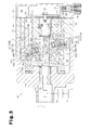
- Fig. 1 is a longitudinal cross-sectional view of the variable displacement swash plate type compressor (hereinafter, simply referred to as the compressor) 10.
- the left end of the compressor 10 in Fig. 1 is defined as the front of the compressor 10, and the right end is defined as the rear of the compressor 10.
- a housing of the compressor 10 includes a cylinder block 11, a front housing member 12 secured to the front end of the cylinder block 11, and a rear housing member 14 secured to the rear end of the cylinder block 11 with a valve plate assembly 13 in between.
- the cylinder block 11 and the front housing member 12 define a crank chamber 15.
- a drive shaft 16 is rotatably arranged between the cylinder block 11 and the front housing member 12 and extends through the crank chamber 15.
- the drive shaft 16 is coupled to a power source of the vehicle, which is an engine E in this embodiment, through a clutchless type power transmission mechanism PT, which constantly transmits power. Therefore, the drive shaft 16 is always rotated by the power supply from the engine E when the engine E is running.
- a rotor 17 is coupled to the drive shaft 16 and is located in the crank chamber 15.
- the rotor 17 rotates integrally with the drive shaft 16.
- the crank chamber 15 accommodates a substantially disk-like first swash plate 18.
- a through hole 18a is formed at the center of the first swash plate 18.
- the drive shaft 16 is inserted through the through hole 18a of the first swash plate 18.
- the first swash plate 18 is supported by the drive shaft 16 via the through hole 18a to be slidable and tiltable with respect to the drive shaft 16.
- a hinge mechanism 19 is located between the rotor 17 and the first swash plate 18.
- the hinge mechanism 19 includes two rotor protrusions 41 (one of the protrusions 41 located toward the front of the sheet of Fig. 1 is not shown), which protrude from the rear surface of the rotor 17, and a swash plate protrusion 42, which protrudes from the front surface of the first swash plate 18 toward the rotor 17.
- the distal end of the swash plate protrusion 42 is inserted between the two rotor protrusions 41. Therefore, rotational force of the rotor 17 is transmitted to the first swash plate 18 via the rotor protrusions 41 and the swash plate protrusion 42.
- a substantially cylindrical support portion 39 projects at the center of the rear surface of the first swash plate 18 to surround the drive shaft 16.
- a disk-like second swash plate 51 is arranged outward of the support portion 39 of the first swash plate 18.
- a support hole 51a is formed at the center of the second swash plate 51. The support portion 39 is inserted in the support hole 51a.
- the radius of the second swash plate 51 is substantially the same as that of the first swash plate 18.
- a radial bearing 52 is provided between the outer circumferential surface of the support portion 39 and the inner circumferential surface of the support hole 51a of the second swash plate 51.
- a thrust bearing 53 is provided between the rear surface of the first swash plate 18 and the front surface of the second swash plate 51.
- the thrust bearing 53 has rolling elements, which are rollers 53a in this embodiment, and the rollers 53a are rotatably held by a retainer 53b.
- the second swash plate 51 is supported by the first swash plate 18 (the support portion 39) via the radial bearing 52 and the thrust bearing 53 such that the second swash plate 51 rotates relative to and tilt integrally with the first swash plate 18.
- a cam portion 43 is formed at the proximal end of the rotor protrusions 41.
- a cam surface 43a is formed on the rear end face of the cam portion 43 facing the first swash plate 18.
- the distal end of the swash plate protrusion 42 slidably abuts against the cam surface 43a of the cam portion 43. Therefore, the hinge mechanism 19 guides the inclination of the first swash plate 18 and the second swash plate 51 as the distal end of the swash plate protrusion 42 moves toward and apart from the drive shaft 16 along the cam surface 43a of the cam portion 43.
- Cylinder bores 22 are formed in the cylinder block 11 about the axis L of the drive shaft 16 at equal angular intervals and extend in the front-rear direction (left-right direction on the sheet of Fig. 1).
- a single head piston 23 is accommodated in each cylinder bore 22 to be movable in the front-rear direction.
- the front and rear openings of each cylinder bore 22 are closed by the front end face of the valve plate assembly 13 and the associated piston 23.
- Each cylinder bore 22 defines a compression chamber 24. The volume of each compression chamber 24 changes according to the reciprocation of the corresponding piston 23.
- Each piston 23 is formed by coupling, in the front-rear direction, a columnar head portion 37, which is inserted in the associated cylinder bore 22, and a neck 38 located in the crank chamber 15 outside the cylinder bore 22.
- the head portions 37 and the necks 38 are formed of an aluminum based metal material (pure aluminum or an aluminum alloy).
- a pair of shoe seats 38a are formed in each neck 38.
- Each neck 38 accommodates semispherical first and second shoes 25A, 25B.
- the first shoe 25A and the second shoe 25B are formed of iron based metal material.
- "semisphere” refers not only to a half of a sphere, but also to a shape that includes part of a spherical surface of a sphere.
- the first shoe 25A and the second shoe 25B are each received by the corresponding shoe seat 38a via a semispherical surface 25a.
- the semispherical surface 25a of the first shoe 25A and the semispherical surface 25a of the second shoe 25B are located on the same spherical surface defined about a point P.
- Each piston 23 is coupled to the outer circumferential portion of the first swash plate 18 and the second swash plate 51 via the first shoe 25A and the second shoe 25B.
- the first shoe 25A located opposite to the compression chamber 24 abuts against the front surface of the first swash plate 18 via a planar sliding surface 25b provided opposite to the semispherical surface 25a.
- the second shoe 25B located toward the compression chamber 24, that is, the one that receives reaction force of compression abuts against the rear surface of the second swash plate 51 via a sliding surface 25b provided opposite to the semispherical surface 25a.
- An intake chamber 26 and a discharge chamber 27 are defined between the valve plate assembly 13 and the rear housing member 14 in the housing of the compressor 10.
- the valve plate assembly 13 includes intake ports 28 and intake valves 29 located between the compression chambers 24 and the intake chamber 26.
- the valve plate assembly 13 also includes discharge ports 30 and discharge valves 31 located between the compression chambers 24 and the discharge chamber 27.
- refrigerant of the refrigeration circuit carbon dioxide is used.
- Refrigerant gas introduced into the intake chamber 26 from an external circuit, which is not shown, is drawn into each compression chamber 24 via the associated intake port 28 and the intake valve 29 as the corresponding piston 23 moves from the top dead center position to the bottom dead center position.
- the refrigerant gas that is drawn into the compression chamber 24 is compressed to a predetermined pressure as the piston 23 is moved from the bottom dead center position to the top dead center position, and is discharged to the discharge chamber 27 through the associated discharge port 30 and the discharge valve 31.
- the refrigerant gas in the discharge chamber 27 is then conducted to the external circuit.
- a bleed passage 32, a supply passage 33, and a control valve 34 are provided in the housing of the compressor 10.
- the bleed passage 32 connects the crank chamber 15 to the intake chamber 26.
- the supply passage 33 connects the discharge chamber 27 to the crank chamber 15.
- the control valve 34 which is a conventional electromagnetic valve, is located in the supply passage 33.
- the opening degree of the control valve 34 is adjusted by controlling power supply from the outside to control the balance between the flow rate of highly pressurized discharge gas supplied to the crank chamber 15 through the supply passage 33 and the flow rate of gas conducted out of the crank chamber 15 through the bleed passage 32.
- the pressure in the crank chamber 15 is thus determined.
- the difference between the pressure in the crank chamber 15 and the pressure in the compression chamber 24 is changed, which in turn varies the inclination angle of the first swash plate 18 and the second swash plate 51. Accordingly, the stroke of each piston 23, or the compressor displacement is adjusted.
- the opening degree of the control valve 34 when the opening degree of the control valve 34 is reduced, the pressure in the crank chamber 15 is reduced. Therefore, the inclination angle of the first swash plate 18 and the second swash plate 51 increases, thereby increasing the stroke of each piston 23. Thus, the displacement of the compressor 10 is increased.
- the opening degree of the control valve 34 increases, the pressure in the crank chamber 15 is increased. Therefore, the inclination angle of the first swash plate 18 and the second swash plate 51 is reduced, thereby reducing the stroke of each piston 23.
- the displacement of the compressor 10 is reduced.
- the support portion 39 of the first swash plate 18 supporting the second swash plate 51 is provided at a position decentered from the axis M1 of the first swash plate 18 toward the piston 23A located at the top dead center position.
- the support portion 39 is provided at a position decentered toward a section of the first swash plate (toward the hinge mechanism 19) that causes any of the pistons 23 to be located at the top dead center position as viewed in the radial direction of the first swash plate 18 from the axis M1.
- the second swash plate 51, the radial bearing 52, and the thrust bearing 53 are decentered from the first swash plate 18 toward the piston 23A located at the top dead center position. Therefore, the axis M2 of the second swash plate 51, the radial bearing 52, and the thrust bearing 53 is slightly displaced in parallel from the axis M1 of the first swash plate 18 toward the center point P of the first shoe 25A and the second shoe 25B of the piston 23A located at the top dead center position (for example, 0.05 to 5 mm, although the displacement is exaggerated in Figs 1 and 2).
- part of the outer circumferential edge portion of the second swash plate 51 corresponding to the vicinity of the piston 23A located at the top dead center position slightly protrudes in the radial direction of the first swash plate 18 from the outer circumferential edge portion of the first swash plate 18. Therefore, for example, as compared to a case where the second swash plate 51 is not decentered from the first swash plate 18, the contact area between the second shoe 25B of the piston 23 located in the vicinity of the top dead center position and the second swash plate 51 is increased.
- Part of the outer circumferential edge portion of the second swash plate 51 corresponding to the vicinity of the piston 23B located at the bottom dead center position is located radially inward of the first swash plate 18 from the outer circumferential edge portion of the first swash plate 18. That is, part of the outer circumferential edge portion of the second swash plate 51 corresponding to the vicinity of the hinge mechanism 19 is located radially inward of the first swash plate 18 than the outer circumferential edge portion of the first swash plate 18. Therefore, for example, as compared to a case where the second swash plate 51 is not decentered from the first swash plate 18, the contact area between the second shoe 25B of the piston 23 located in the vicinity of the bottom dead center position and the second swash plate 51 is reduced.
- reaction force of compression applied to the second shoe 25B of the piston 23 located in the vicinity of the bottom dead center position is far smaller than the reaction force of compression applied to the second shoe 25B of the piston 23 located in the vicinity of the top dead center position. Therefore, even if the contact area between the second shoe 25B of the piston 23 located in the vicinity of the bottom dead center position and the second swash plate 51 is reduced, no problem arises in the durability of the second swash plate 51 and the second shoe 25B.
- Part of the outer circumferential edge portion of the first swash plate 18 corresponding to the piston 23A located at the top dead center position and circumferentially adjacent parts thereof are provided with an inclined surface (a chamfer) on a salient corner 18b opposite to the second swash plate 51. That is, part of the outer circumferential edge portion of the second swash plate 51 corresponding to the vicinity of the hinge mechanism 19 is provided with the inclined surface (the chamfer) on the salient corner 18b opposite to the second swash plate 51.
- part of the outer circumferential edge portion of the first swash plate 18 corresponding to a circumferential range of the first swash plate 18 that arranges any of the pistons 23 at the top dead center position is provided with the inclined surface on the salient corner 18b opposite to the piston 23A.
- the inclined surface (the chamfer) on the salient corner 18b is the largest at the part corresponding to the piston 23A located at the top dead center position, and gradually becomes smaller along the circumferential direction.
- the inclined surface (the chamfer) on the salient corner 18b is provided within a range of quarter to half the circumference of the first swash plate 18 with the part corresponding to the piston 23A located at the top dead center position arranged in the middle.
- Part of the outer circumferential edge portion of the first swash plate 18 corresponding to the piston 23B located at the bottom dead center position and circumferentially adjacent parts thereof are provided with an inclined surface (a chamfer) on a salient corner 18c toward the second swash plate 51. That is, part of the outer circumferential edge portion of the first swash plate 18 corresponding to a circumferential range of the first swash plate 18 that arranges the piston 23B at the bottom dead center position is provided with the inclined surface on the salient corner 18c opposite to the piston 23B.
- the inclined surface (the chamfer) is the largest at the part corresponding to the piston 23B located at the bottom dead center position, and gradually becomes smaller along the circumferential direction.
- the inclined surface (the chamfer) of the salient corner 18c is provided within a range of quarter to half the circumference of the first swash plate 18 with the part corresponding to the piston 23B located at the bottom dead center position arranged in the middle.
- the inclined surface (the chamfer) on the salient corner 18c is substantially the same size as the inclined surface (the chamfer) on the salient corner 18b taking into consideration of the balance of the weight around the axis M1 of the first swash plate 18.
- the first embodiment has the following advantages.
- the first swash plate 18 supports the second swash plate 51 in a suitable manner, and a great reaction force of compression applied to the second swash plate 51 via the second shoe 25B of the piston 23 located in the vicinity of the top dead center position is received by the first swash plate 18 via the second swash plate 51 in a suitable manner. This improves the durability of the second swash plate 51.
- the center portion of the sliding surface 25b of the first shoe 25A bulges toward the first swash plate 18 (see Fig. 4. The bulge is exaggerated in Fig. 4).
- the sliding surface 25b of the second shoe 25B is flat.
- a radial bearing 52A which is a roller bearing, is located between the support portion 39, which forms the inner circumferential portion of the first swash plate 18, and an inner circumferential portion 51-1 of the second swash plate 51, and more specifically, between the outer circumferential surface of the support portion 39 and the inner circumferential surface of the support hole 51a of the second swash plate 51.
- the radial bearing 52A includes an outer race 52a attached to the inner circumferential surface of the support hole 51a of the second swash plate 51, an inner race 52b attached to the outer circumferential surface of the support portion 39 of the first swash plate 18, and rolling elements, which are rollers 52c in the second embodiment.
- the rollers 52c are located between the outer race 52a and the inner race 52b.
- the thrust bearing 53 which is a roller bearing, is located between the first shoes 25A and the second shoes 25B and between the outer circumferential portion 18-1 of the first swash plate 18 and the outer circumferential portion 51-2 of the second swash plate 51.
- the thrust bearing 53 has rolling elements, which are the rollers 53a in the second embodiment, and the rollers 53a are rotatably held by the retainer 53b.
- the thrust bearing 53 has an annular race 55 located between the rollers 53a and the first swash plate 18.
- the race 55 is formed by carburizing and heat treating base material formed of mild steel such as SPC.
- the corners at both ends of each roller 53a are chamfered to prevent the second swash plate 51 and the race 55 from being damaged by the rollers 53a abutting against the second swash plate 51 and the race 55.
- An annular engaging portion 18d is provided on the rear surface of the first swash plate 18 at the outermost circumference of the outer circumferential portion 18-1 and projects toward the second swash plate 51.
- the race 55 is located inward of the engaging portion 18d and is engaged with the first swash plate 18 at the radially outward edge of the race 55 by the abutment between the outer circumferential edge of the race 55 and the engaging portion 18d.
- the race 55 is guided by the engaging portion 18d to rotate relative to the first swash plate 18.
- the second swash plate 51 is supported by the first swash plate 18 via the radial bearing 52A and the thrust bearing 53 such that the second swash plate 51 rotates relative to and tilts integrally with the first swash plate 18. Therefore, when the first swash plate 18 is rotated, the radial bearing 52A and the thrust bearing 53 cause rolling motion between the first swash plate 18 and the second swash plate 51. Therefore, the mechanical loss caused by sliding motion between the first swash plate 18 and the second swash plate 51 is converted to the mechanical loss caused by the rolling motion. This significantly suppresses the mechanical loss in the compressor.
- the plate thickness Y1 of the inner circumferential portion 51-1 of the second swash plate 51 that is supported by the radial bearing 52A is greater than the plate thickness Y2 of the outer circumferential portion 51-2 of the second swash plate 51 that is supported by the thrust bearing 53. More specifically, the plate thickness Y2 of the outer circumferential portion 51-2 of the second swash plate 51 is half or more of the plate thickness X of the outer circumferential portion 18-1 of the first swash plate 18 and thinner than the plate thickness X of the outer circumferential portion 18-1 of the first swash plate 18. Also, the plate thickness Y1 of the inner circumferential portion 51-1 of the second swash plate 51 is thicker than the plate thickness X of the outer circumferential portion 18-1 of the first swash plate 18.
- the plate thickness of the inner circumferential portion 51-1 of the second swash plate 51 is designed to be greater than that of the outer circumferential portion 51-2 of the second swash plate 51 (Y1 > Y2) by providing a cylindrical first projection 56, which projects toward the first swash plate 18, and a cylindrical second projection 57, which projects opposite to the first swash plate 18.
- the first projection 56 and the second projection 57 are arranged coaxial with the support hole 51a, and the inner circumferential surfaces of the first projection 56 and the second projection 57 form part of the inner circumferential surface of the support hole 51a.
- the outer diameter Z2 of the second projection 57 is smaller than the outer diameter Z1 of the first projection 56.
- the outer circumferential corner 57a of the distal end face of the second projection 57 is entirely chamfered to form a tapered face.
- the second embodiment provides the following advantages in addition to the advantages of the first embodiment.
- the support portion 39 is not decentered from the axis M1 of the first swash plate 18. That is, the second swash plate 51, the radial bearing 52A (see Fig. 3), and the thrust bearing 53 (including the race 55) are not decentered from the first swash plate 18.
- the salient corner 18c need not be chamfered as shown in Fig. 5 because the salient corner 18c toward the second swash plate 51 does not significantly project in the radial direction from the second swash plate 51.
- the PCD of the thrust bearing 53 is greater than the diameter of an imaginary cylinder defined about the axes M1, M2 of the first swash plate 18 and the second swash plate 51 and passes through the center points P of the first shoe 25A and the second shoe 25B.
- the thrust bearing 53 (the rollers 53a) receives the reaction force of compression transmitted through the second swash plate 51 in a suitable manner, which improves the durability.
- the "PCD" of the thrust bearing 53 refers to the diameter of an imaginary cylinder having the axis at the center of the thrust bearing 53 (at the axes M1, M2 of the first swash plate 18 and the second swash plate 51) and passes through the mid point of the rotating axis of the rollers 53a.
- the rotor 17 is fixed to the drive shaft 16, and a swash plate 58 is supported on the drive shaft 16.
- the swash plate 58 is permitted to slide along and incline with respect to the drive shaft.
- Coupling pieces 59, 60 are fixed to the swash plate 58, and guide pins 61, 62 are fixed to the coupling pieces 59, 60.
- a pair of guide holes 171 (only one is shown) is formed in the rotor 17. Head portions of the guide pins 61, 62 are slidably fitted to the guide holes 171. The engagement of the guide holes 171 with the guide pins 61, 62 allows the swash plate 58 to incline with respect to the axial direction of the drive shaft 16 and rotate integrally with the drive shaft 16.
- the inclination of the swash plate 58 is guided by the guide holes 171 and the guide pins 61, 62, and the drive shaft 16.
- the coupling pieces 59, 60, the guide pins 61, 62, and the guide holes 171 form a hinge mechanism 19A.
- the swash plate 58 shown by a solid line in Fig. 6 is in the maximum inclination state of the swash plate 58.
- the swash plate 58 shown by a chain line in Fig. 6 is in the minimum inclination state.
- Part of the outer circumferential edge portion of the swash plate 58 corresponding to the piston 23A located at the top dead center position and circumferentially adjacent parts thereof are provided with an inclined surface on a salient corner 58a opposite to the piston 23. That is, part of the outer circumferential edge portion of the swash plate 58 corresponding to the vicinity of the hinge mechanism 19A is provided with the inclined surface on the salient corner 58a toward the hinge mechanism 19A. In other words, part of the outer circumferential edge portion of the swash plate 58 corresponding to a circumferential range of the swash plate 58 that arranges the piston 23A at the top dead center position is provided with the inclined surface on the salient corner 58a opposite to the piston 23. As shown in Fig. 7, part of the inclined surface of the salient corner 58a corresponding to the piston 23 located at the top dead center position is the largest, and gradually becomes smaller along the circumferential direction.
- the inclined surface provided on the salient corner 58a is located on the circumferential surface of an imaginary cylinder C having an axis M3 that is parallel to the axis L of the drive shaft 16.
- the axis M3 is displaced with respect to the axis L from the piston 23A located at the top dead center position toward the drive shaft 16.
- the diameter of the imaginary cylinder C is greater than or equal to the diameter of the swash plate 58.
- the salient corner 58a opposite to the piston 23 significantly projects in the radial direction of the drive shaft 16 when the swash plate 58 tilts with respect to the drive shaft 16. Therefore, providing the inclined surface at the projecting portion (part of the salient corner 58a) of the swash plate 58 permits the swash plate 58 to be enlarged while suppressing reduction in the durability and enlargement of the pistons 23. Therefore, a significant reaction force of compression applied to the swash plate 58 is received in a suitable manner via the second shoe 25B of the piston 23 located in the vicinity of the top dead center position. This improves the durability of the swash plate 58.
Landscapes
- Engineering & Computer Science (AREA)
- Mechanical Engineering (AREA)
- General Engineering & Computer Science (AREA)
- Manufacturing & Machinery (AREA)
- Compressors, Vaccum Pumps And Other Relevant Systems (AREA)
Abstract
Description
- The present invention relates to a variable displacement swash plate type compressor that forms, for example, part of a refrigeration circuit and compresses refrigerant gas.
- As shown in Fig. 9, such a swash plate type compressor includes a
swash plate 92, which is coupled to adrive shaft 91 to be rotatable integrally with thedrive shaft 91.Single head pistons 94 are coupled to the outer circumferential portion of theswash plate 92 with pairs ofsemispherical shoes swash plate 92 is rotated by rotation of thedrive shaft 91, theswash plate 92 slides with respect to theshoes pistons 94 to reciprocate, thereby compressing refrigerant gas. - Each pair of
shoes shoes swash plate 92. The rotation of theshoes shoes swash plate 92. More specifically, the circumferential velocity of the outer circumference of theswash plate 92 is greater than that of the inner circumference of theswash plate 92. - That is, the swash plate type compressor shown in Fig. 9 is configured such that the
shoes swash plate 92. Therefore, theshoes shoes swash plate 92. This increases the mechanical loss particularly at the sliding portion between eachpiston 94 and thecorresponding shoe 93B that receives reactive force of compression, and causes problems such as seizure at the sliding portions. - To solve such problems, for example, a technique shown in Fig. 10 has been proposed (for example, patent document 1). That is, an
annular step 90a is provided at the center of a rear surface (a surface facing rightward in Fig. 10) of a swash plate (hereinafter, referred to as a first swash plate 90). An annular sliding plate (hereinafter, referred to as a second swash plate 95) is arranged outward of thestep 90a of thefirst swash plate 90. Thesecond swash plate 95 is supported to be coaxial with and rotatable relative to thefirst swash plate 90. The outer circumferential portion of thesecond swash plate 95 is arranged between thefirst swash plate 90 and thesecond shoes 93B to be slidable with respect to thefirst swash plate 90 and thesecond shoes 93B. - Therefore, when the
first swash plate 90 is rotated, thefirst swash plate 90 slides relative to thesecond swash plate 95, which reduces the rotation speed of thesecond swash plate 95 as compared to the rotation speed of thefirst swash plate 90. This reduces the relative rotation speed of thesecond swash plate 95 and thesecond shoes 93B as compared to the relative rotation speed of thesecond shoes 93B and thefirst swash plate 90. As a result, the rotation of eachsecond shoe 93B about the axis S caused by the relative rotation of thesecond swash plate 95 and thesecond shoes 93B is suppressed, which suppresses mechanical loss and occurrence of problems. - A configuration has also been proposed in which rolling elements are provided between the
first shoes 93A and thesecond shoes 93B and between thefirst swash plate 90 and the second swash plate 95 (for example, patent document 2). In the patent document 2, a race of a thrust bearing arranged toward thesecond shoe 93B can be considered as thesecond swash plate 95. With this configuration, thefirst swash plate 90 reliably slides with respect to thesecond swash plate 95, which significantly reduces the relative rotation speed of thesecond swash plate 95 and thesecond shoes 93B as compared to the relative rotation speed of thesecond shoes 93B and thefirst swash plate 90. - However, according to the swash plate configuration including the
second swash plate 95 and the rolling element in addition to thefirst swash plate 90, the thickness between thefirst shoes 93A and thesecond shoes 93B is increased.
Thefirst swash plate 90, which tilts with respect to thedrive shaft 91, has asalient corner 90b at the outer circumferential edge portion corresponding to the vicinity of thepiston 94 located at the top dead center position (the state shown in Fig. 10). Thesalient corner 90b is provided at the outer circumferential edge portion opposite to thesecond swash plate 95 and significantly protrudes in the radial direction (upward in the drawing) of thedrive shaft 91. Furthermore, thesecond swash plate 95, which tilts with respect to thedrive shaft 91, has a salient corner 95b at the outer circumferential edge portion corresponding to the vicinity of thepiston 94 located at the bottom dead center position (not shown). The salient corner 95b is provided at the outer circumferential edge portion opposite to thefirst swash plate 90 and significantly protrudes in the radial direction of thedrive shaft 91. - When the
salient corner 90b of thefirst swash plate 90 and the salient corner 95b of thesecond swash plate 95 significantly protrude in the radial direction of thedrive shaft 91, part of eachpiston 94 corresponding to the protruding portions needs to be made thin, or thepistons 94 need to be enlarged in the radial direction to avoid interference with the protruding portions. Reducing the thickness of thepistons 94 leads to reduction in the durability, and enlargement of thepistons 94 leads to enlargement of the swash plate type compressor. Therefore, in the prior art, when the thickness of the swash plate configuration needs to be increased, the radii of thefirst swash plate 90 and thesecond swash plate 95 are reduced to avoid interference of thesalient corners 90b, 95b with thepistons 94. - However, when the radii of the
first swash plate 90 and thesecond swash plate 95 are reduced, particularly thepiston 94 located in the vicinity of the top dead center position (in a compression stroke) has a reduced contact area between thesecond shoe 93B, which receives a significant reaction force of compression, and thesecond swash plate 95. This undesirably reduces the durability of thesecond swash plate 95 and thesecond shoe 93B. - It has become a common practice to use carbon dioxide as refrigerant of the refrigeration circuit. When carbon dioxide refrigerant is used, the pressure in the refrigeration circuit becomes extremely high as compared to a case where chlorofluorocarbon refrigerant (for example, R134a) is used. Therefore, the reaction force of compression applied to the
pistons 94 is increased in the swash plate type compressor, and the aforementioned problem (reduction in the durability of thesecond swash plate 95 and thesecond shoes 93B) has become a significant matter of concern. - Patent Document 1: Japanese Laid-Open Patent Publication No. 8-338363 (page 4, Fig. 1)
- Patent Document 2: Japanese Laid-Open Patent Publication No. 8-28447 (page 3, Fig. 1)
- Accordingly, it is an objective of the present invention to provide a variable displacement swash plate type compressor that improves the durability of a swash plate and shoes while suppressing reduction in the durability of pistons and enlargement of the pistons.
- To achieve the above objective, the present invention provides a variable displacement swash plate type compressor. A swash plate is coupled to a drive shaft to be rotatable integrally with the drive shaft. Pistons are coupled to the swash plate via shoes. Rotation of the drive shaft rotates the swash plate, which causes the pistons to reciprocate and compress gas. The displacement is changed by varying the inclination angle of the swash plate. An inclined surface is provided at part of the entire outer circumferential edge portion of the swash plate.
- Providing the inclined surface at a projecting salient corner of the outer circumferential edge portion of the swash plate, which inclines with respect to the drive shaft, permits the diameter of the swash plate to be increased while suppressing decrease of the durability and enlargement of the pistons. Therefore, a significant reaction force of compression applied to the swash plate via the shoes is received in a suitable manner. This improves the durability of the swash plate and the shoes.
- In a preferred embodiment, part of the outer circumferential edge portion of the swash plate corresponding to the piston located at the top dead center position is provided with the inclined surface on a salient corner opposite to the piston. That is, part of the outer circumferential edge portion of the swash plate corresponding to a circumferential range of the swash plate that arranges any of the pistons at the top dead center position is provided with the inclined surface on the salient corner opposite to the piston.
- At the outer circumferential edge portion of the swash plate that corresponds to the piston located at the top dead center position, the salient corner opposite to the piston significantly projects in the radial direction of the drive shaft when the swash plate tilts with respect to the drive shaft. Therefore, a significant reaction force of compression applied to the swash plate via the shoe of the piston located in the vicinity of the top dead center position is received in a suitable manner. This improves the durability of the swash plate and the shoes.
- In a preferred embodiment, part of the outer circumferential edge portion of the swash plate corresponding to the piston located at the bottom dead center position is provided with the inclined surface on a salient corner toward the piston. That is, part of the outer circumferential edge portion of the swash plate corresponding to a circumferential range of the swash plate that arranges any of the pistons at the bottom dead center position is provided with the inclined surface on the salient corner toward the piston.
- At the outer circumferential edge portion of the swash plate corresponding to the piston located at the bottom dead center position, the salient corner toward the piston significantly projects in the radial direction of the drive shaft. Therefore, chamfering the projecting portion of the swash plate permits the diameter of the first swash plate to be increased while suppressing decrease of the durability and enlargement of the pistons.
- In the preferred embodiment, the swash plate includes a first swash plate, which is coupled to the drive shaft to be rotatable integrally with the drive shaft, and a second swash plate, which is supported by the first swash plate. The pistons are coupled to the first and second swash plates via first shoes, which abut against the first swash plate, and second shoes, which abut against the second swash plate and receive a reaction force of compression. Part of the outer circumferential edge of the first swash plate corresponding to the piston located at the top dead center position is provided with the inclined surface on a salient corner opposite to the second swash plate. That is, part of the outer circumferential edge portion of the first swash plate corresponding to a circumferential range of the first swash plate that arranges any of the pistons at the top dead center position is provided with the inclined surface on the salient corner opposite to the first swash plate.
- At the outer circumferential edge portion of the first swash plate that corresponds to the piston located at the top dead center position, the salient corner opposite to the second swash plate significantly projects in the radial direction of the drive shaft when the first swash plate tilts with respect to the drive shaft. Therefore, chamfering the projecting portion of the first swash plate permits the diameter of the first swash plate to be increased while suppressing decrease of the durability and enlargement of the pistons. Therefore, the first swash plate supports the second swash plate in a suitable manner, and a great reaction force of compression applied to the second swash plate via the second shoe of the piston located in the vicinity of the top dead center position is received by the first swash plate via the second swash plate in a suitable manner. This improves the durability of the second swash plate and the second shoes.
- In the preferred embodiment, part of the outer circumferential edge portion of the first swash plate corresponding to the piston located at the bottom dead center position is provided with the inclined surface on a salient corner toward the second swash plate. That is, part of the outer circumferential edge portion of the first swash plate corresponding to a circumferential range of the first swash plate that arranges any of the pistons at the bottom dead center position is provided with the inclined surface on the salient corner toward the second swash plate.
- At the outer circumferential edge portion of the swash plate corresponding to the piston located at the bottom dead center position, the salient corner toward the piston significantly projects in the radial direction of the drive shaft. Therefore, chamfering the projecting portion of the swash plate permits the diameter of the first swash plate to be increased while suppressing decrease of the durability and enlargement of the pistons.
- In the preferred embodiment, the gas is refrigerant used in a refrigeration circuit, and carbon dioxide is used as the refrigerant.
- When carbon dioxide refrigerant is used, as compared to a case where chlorofluorocarbon refrigerant (for example, R134a) is used, the pressure in the refrigeration circuit becomes extremely high. Therefore, the reaction force of compression applied to the pistons in the variable displacement swash plate type compressor is increased, which increases the pressure between the swash plate and the shoes. The above mentioned embodiments of the present invention according to any one of
claims 1 to 5 are particularly effective in improving the durability of the swash plate and the shoes while suppressing decrease of the durability and enlargement of the pistons. -
- Fig. 1 is a longitudinal cross-sectional view illustrating a variable displacement swash plate type compressor according to a first embodiment of the present invention;
- Fig. 2 is an enlarged partial view of Fig. 1 with the first and second swash plates not being sectioned;
- Fig. 3 is a longitudinal cross-sectional view illustrating a variable displacement swash plate type compressor according to a second embodiment of the present invention;
- Fig. 4 is an enlarged partial view of Fig. 3 with the first and second swash plates not being sectioned (partially cut away) and part of the first and second shoes being sectioned;
- Fig. 5 is an enlarged partial view illustrating a swash plate configuration according to a third embodiment of the present invention;
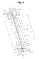
- Fig. 6 is a longitudinal cross-sectional view illustrating a variable displacement swash plate type compressor according to a fourth embodiment of the present invention;
- Fig. 7 is a cross-sectional view taken along line A-A of Fig. 6;
- Fig. 8 is an enlarged partial cross-sectional view of Fig. 6;
- Fig. 9 is a longitudinal cross-sectional view illustrating a prior art variable displacement swash plate type compressor; and
- Fig. 10 is a partial cross-sectional view illustrating a prior art technique.
- A variable displacement swash plate type compressor according to first to fourth embodiments of the present invention will now be described. The compressor forms part of a refrigeration circuit of a vehicle air-conditioning system.
- The first embodiment will be described with reference to Figs. 1 and 2.
- Fig. 1 is a longitudinal cross-sectional view of the variable displacement swash plate type compressor (hereinafter, simply referred to as the compressor) 10. The left end of the
compressor 10 in Fig. 1 is defined as the front of thecompressor 10, and the right end is defined as the rear of thecompressor 10. - As shown in Fig. 1, a housing of the
compressor 10 includes acylinder block 11, afront housing member 12 secured to the front end of thecylinder block 11, and arear housing member 14 secured to the rear end of thecylinder block 11 with avalve plate assembly 13 in between. - In the housing of the
compressor 10, thecylinder block 11 and thefront housing member 12 define a crankchamber 15. Adrive shaft 16 is rotatably arranged between thecylinder block 11 and thefront housing member 12 and extends through thecrank chamber 15. Thedrive shaft 16 is coupled to a power source of the vehicle, which is an engine E in this embodiment, through a clutchless type power transmission mechanism PT, which constantly transmits power. Therefore, thedrive shaft 16 is always rotated by the power supply from the engine E when the engine E is running. - A
rotor 17 is coupled to thedrive shaft 16 and is located in thecrank chamber 15. Therotor 17 rotates integrally with thedrive shaft 16. Thecrank chamber 15 accommodates a substantially disk-like firstswash plate 18.
A throughhole 18a is formed at the center of the firstswash plate 18. Thedrive shaft 16 is inserted through the throughhole 18a of the firstswash plate 18. The firstswash plate 18 is supported by thedrive shaft 16 via the throughhole 18a to be slidable and tiltable with respect to thedrive shaft 16. Ahinge mechanism 19 is located between therotor 17 and the firstswash plate 18. - The
hinge mechanism 19 includes two rotor protrusions 41 (one of theprotrusions 41 located toward the front of the sheet of Fig. 1 is not shown), which protrude from the rear surface of therotor 17, and aswash plate protrusion 42, which protrudes from the front surface of the firstswash plate 18 toward therotor 17. The distal end of theswash plate protrusion 42 is inserted between the tworotor protrusions 41. Therefore, rotational force of therotor 17 is transmitted to the firstswash plate 18 via therotor protrusions 41 and theswash plate protrusion 42. - A substantially
cylindrical support portion 39 projects at the center of the rear surface of the firstswash plate 18 to surround thedrive shaft 16. A disk-like secondswash plate 51 is arranged outward of thesupport portion 39 of the firstswash plate 18. Asupport hole 51a is formed at the center of thesecond swash plate 51. Thesupport portion 39 is inserted in thesupport hole 51a. The radius of thesecond swash plate 51 is substantially the same as that of the firstswash plate 18. - A
radial bearing 52 is provided between the outer circumferential surface of thesupport portion 39 and the inner circumferential surface of thesupport hole 51a of thesecond swash plate 51. Athrust bearing 53 is provided between the rear surface of the firstswash plate 18 and the front surface of thesecond swash plate 51. Thethrust bearing 53 has rolling elements, which arerollers 53a in this embodiment, and therollers 53a are rotatably held by aretainer 53b. - The
second swash plate 51 is supported by the first swash plate 18 (the support portion 39) via theradial bearing 52 and the thrust bearing 53 such that thesecond swash plate 51 rotates relative to and tilt integrally with the firstswash plate 18. - A
cam portion 43 is formed at the proximal end of therotor protrusions 41. Acam surface 43a is formed on the rear end face of thecam portion 43 facing the firstswash plate 18. The distal end of theswash plate protrusion 42 slidably abuts against thecam surface 43a of thecam portion 43. Therefore, thehinge mechanism 19 guides the inclination of the firstswash plate 18 and thesecond swash plate 51 as the distal end of theswash plate protrusion 42 moves toward and apart from thedrive shaft 16 along thecam surface 43a of thecam portion 43. - Cylinder bores 22 are formed in the
cylinder block 11 about the axis L of thedrive shaft 16 at equal angular intervals and extend in the front-rear direction (left-right direction on the sheet of Fig. 1). Asingle head piston 23 is accommodated in each cylinder bore 22 to be movable in the front-rear direction. The front and rear openings of each cylinder bore 22 are closed by the front end face of thevalve plate assembly 13 and the associatedpiston 23. Each cylinder bore 22 defines acompression chamber 24. The volume of eachcompression chamber 24 changes according to the reciprocation of thecorresponding piston 23. - Each
piston 23 is formed by coupling, in the front-rear direction, acolumnar head portion 37, which is inserted in the associated cylinder bore 22, and aneck 38 located in thecrank chamber 15 outside the cylinder bore 22. Thehead portions 37 and thenecks 38 are formed of an aluminum based metal material (pure aluminum or an aluminum alloy). A pair ofshoe seats 38a are formed in eachneck 38. Eachneck 38 accommodates semispherical first andsecond shoes first shoe 25A and thesecond shoe 25B are formed of iron based metal material. In this specification, "semisphere" refers not only to a half of a sphere, but also to a shape that includes part of a spherical surface of a sphere. - The
first shoe 25A and thesecond shoe 25B are each received by the correspondingshoe seat 38a via asemispherical surface 25a. Thesemispherical surface 25a of thefirst shoe 25A and thesemispherical surface 25a of thesecond shoe 25B are located on the same spherical surface defined about a point P. Eachpiston 23 is coupled to the outer circumferential portion of the firstswash plate 18 and thesecond swash plate 51 via thefirst shoe 25A and thesecond shoe 25B. Thefirst shoe 25A located opposite to thecompression chamber 24 abuts against the front surface of the firstswash plate 18 via a planar slidingsurface 25b provided opposite to thesemispherical surface 25a. Thesecond shoe 25B located toward thecompression chamber 24, that is, the one that receives reaction force of compression abuts against the rear surface of thesecond swash plate 51 via a slidingsurface 25b provided opposite to thesemispherical surface 25a. - When the first
swash plate 18 is rotated by the rotation of thedrive shaft 16, thepistons 23 reciprocate in the front-rear direction. - When the first
swash plate 18 is rotated, theradial bearing 52 and the thrust bearing 53 cause the firstswash plate 18 to slide with respect to thesecond swash plate 51. This reduces the rotation speed of thesecond swash plate 51 as compared to the rotation speed of the firstswash plate 18. Therefore, the relative rotation speed of thesecond swash plate 51 and thesecond shoes 25B is reduced as compared to the relative rotation speed of thesecond shoes 25B and the firstswash plate 18. This suppresses the rotation of eachsecond shoe 25B about the axis S (a line that passes through the center of curvature point P of thesemispherical surface 25a and is perpendicular to the slidingsurface 25b) caused by the relative rotation of thesecond swash plate 51 and thesecond shoe 25B. Thus, mechanical loss and occurrence of problems caused by the rotation of thesecond shoes 25B are suppressed. - An
intake chamber 26 and adischarge chamber 27 are defined between thevalve plate assembly 13 and therear housing member 14 in the housing of thecompressor 10. Thevalve plate assembly 13 includesintake ports 28 andintake valves 29 located between thecompression chambers 24 and theintake chamber 26. Thevalve plate assembly 13 also includesdischarge ports 30 anddischarge valves 31 located between thecompression chambers 24 and thedischarge chamber 27. - As refrigerant of the refrigeration circuit, carbon dioxide is used. Refrigerant gas introduced into the
intake chamber 26 from an external circuit, which is not shown, is drawn into eachcompression chamber 24 via the associatedintake port 28 and theintake valve 29 as the correspondingpiston 23 moves from the top dead center position to the bottom dead center position. The refrigerant gas that is drawn into thecompression chamber 24 is compressed to a predetermined pressure as thepiston 23 is moved from the bottom dead center position to the top dead center position, and is discharged to thedischarge chamber 27 through the associateddischarge port 30 and thedischarge valve 31. The refrigerant gas in thedischarge chamber 27 is then conducted to the external circuit. - A
bleed passage 32, asupply passage 33, and acontrol valve 34 are provided in the housing of thecompressor 10. Thebleed passage 32 connects thecrank chamber 15 to theintake chamber 26. Thesupply passage 33 connects thedischarge chamber 27 to the crankchamber 15. Thecontrol valve 34, which is a conventional electromagnetic valve, is located in thesupply passage 33. - The opening degree of the
control valve 34 is adjusted by controlling power supply from the outside to control the balance between the flow rate of highly pressurized discharge gas supplied to the crankchamber 15 through thesupply passage 33 and the flow rate of gas conducted out of thecrank chamber 15 through thebleed passage 32. The pressure in thecrank chamber 15 is thus determined. As the pressure in thecrank chamber 15 varies, the difference between the pressure in thecrank chamber 15 and the pressure in thecompression chamber 24 is changed, which in turn varies the inclination angle of the firstswash plate 18 and thesecond swash plate 51. Accordingly, the stroke of eachpiston 23, or the compressor displacement is adjusted. - For example, when the opening degree of the
control valve 34 is reduced, the pressure in thecrank chamber 15 is reduced. Therefore, the inclination angle of the firstswash plate 18 and thesecond swash plate 51 increases, thereby increasing the stroke of eachpiston 23. Thus, the displacement of thecompressor 10 is increased. In contrast, when the opening degree of thecontrol valve 34 increases, the pressure in thecrank chamber 15 is increased. Therefore, the inclination angle of the firstswash plate 18 and thesecond swash plate 51 is reduced, thereby reducing the stroke of eachpiston 23. Thus, the displacement of thecompressor 10 is reduced. - As shown in Figs. 1 and 2, the
support portion 39 of the firstswash plate 18 supporting thesecond swash plate 51 is provided at a position decentered from the axis M1 of the firstswash plate 18 toward thepiston 23A located at the top dead center position. In other words, thesupport portion 39 is provided at a position decentered toward a section of the first swash plate (toward the hinge mechanism 19) that causes any of thepistons 23 to be located at the top dead center position as viewed in the radial direction of the firstswash plate 18 from the axis M1. Therefore, thesecond swash plate 51, theradial bearing 52, and the thrust bearing 53 (and theretainer 53b) are decentered from the firstswash plate 18 toward thepiston 23A located at the top dead center position. Therefore, the axis M2 of thesecond swash plate 51, theradial bearing 52, and thethrust bearing 53 is slightly displaced in parallel from the axis M1 of the firstswash plate 18 toward the center point P of thefirst shoe 25A and thesecond shoe 25B of thepiston 23A located at the top dead center position (for example, 0.05 to 5 mm, although the displacement is exaggerated in Figs 1 and 2). - Therefore, part of the outer circumferential edge portion of the
second swash plate 51 corresponding to the vicinity of thepiston 23A located at the top dead center position slightly protrudes in the radial direction of the firstswash plate 18 from the outer circumferential edge portion of the firstswash plate 18. Therefore, for example, as compared to a case where thesecond swash plate 51 is not decentered from the firstswash plate 18, the contact area between thesecond shoe 25B of thepiston 23 located in the vicinity of the top dead center position and thesecond swash plate 51 is increased. - Part of the outer circumferential edge portion of the
second swash plate 51 corresponding to the vicinity of thepiston 23B located at the bottom dead center position is located radially inward of the firstswash plate 18 from the outer circumferential edge portion of the firstswash plate 18. That is, part of the outer circumferential edge portion of thesecond swash plate 51 corresponding to the vicinity of thehinge mechanism 19 is located radially inward of the firstswash plate 18 than the outer circumferential edge portion of the firstswash plate 18. Therefore, for example, as compared to a case where thesecond swash plate 51 is not decentered from the firstswash plate 18, the contact area between thesecond shoe 25B of thepiston 23 located in the vicinity of the bottom dead center position and thesecond swash plate 51 is reduced. However, the reaction force of compression applied to thesecond shoe 25B of thepiston 23 located in the vicinity of the bottom dead center position is far smaller than the reaction force of compression applied to thesecond shoe 25B of thepiston 23 located in the vicinity of the top dead center position. Therefore, even if the contact area between thesecond shoe 25B of thepiston 23 located in the vicinity of the bottom dead center position and thesecond swash plate 51 is reduced, no problem arises in the durability of thesecond swash plate 51 and thesecond shoe 25B. - Part of the outer circumferential edge portion of the first
swash plate 18 corresponding to thepiston 23A located at the top dead center position and circumferentially adjacent parts thereof are provided with an inclined surface (a chamfer) on asalient corner 18b opposite to thesecond swash plate 51. That is, part of the outer circumferential edge portion of thesecond swash plate 51 corresponding to the vicinity of thehinge mechanism 19 is provided with the inclined surface (the chamfer) on thesalient corner 18b opposite to thesecond swash plate 51. In other words, part of the outer circumferential edge portion of the firstswash plate 18 corresponding to a circumferential range of the firstswash plate 18 that arranges any of thepistons 23 at the top dead center position is provided with the inclined surface on thesalient corner 18b opposite to thepiston 23A. The inclined surface (the chamfer) on thesalient corner 18b is the largest at the part corresponding to thepiston 23A located at the top dead center position, and gradually becomes smaller along the circumferential direction. The inclined surface (the chamfer) on thesalient corner 18b is provided within a range of quarter to half the circumference of the firstswash plate 18 with the part corresponding to thepiston 23A located at the top dead center position arranged in the middle. - Part of the outer circumferential edge portion of the first
swash plate 18 corresponding to thepiston 23B located at the bottom dead center position and circumferentially adjacent parts thereof are provided with an inclined surface (a chamfer) on asalient corner 18c toward thesecond swash plate 51. That is, part of the outer circumferential edge portion of the firstswash plate 18 corresponding to a circumferential range of the firstswash plate 18 that arranges thepiston 23B at the bottom dead center position is provided with the inclined surface on thesalient corner 18c opposite to thepiston 23B. - The inclined surface (the chamfer) is the largest at the part corresponding to the
piston 23B located at the bottom dead center position, and gradually becomes smaller along the circumferential direction. The inclined surface (the chamfer) of thesalient corner 18c is provided within a range of quarter to half the circumference of the firstswash plate 18 with the part corresponding to thepiston 23B located at the bottom dead center position arranged in the middle. The inclined surface (the chamfer) on thesalient corner 18c is substantially the same size as the inclined surface (the chamfer) on thesalient corner 18b taking into consideration of the balance of the weight around the axis M1 of the firstswash plate 18. - The first embodiment has the following advantages.
- (1-1) The
second swash plate 51 is decentered from the firstswash plate 18 toward thepiston 23A located at the top dead center position. Therefore, the contact area between thesecond shoe 25B of thepiston 23 located in the vicinity of the top dead center position and thesecond swash plate 51 is increased without increasing the diameter of the firstswash plate 18 and thesecond swash plate 51. Therefore, thesecond swash plate 51 reliably slides with respect to thesecond shoes 25B, and the durability of thesecond swash plate 51 and thesecond shoes 25B is improved while suppressing decrease of the durability and enlargement of thepistons 23. - (1-2) According to the swash plate configuration that includes the thrust bearing 53 in addition to the first
swash plate 18 and thesecond swash plate 51 as in the first embodiment, the thickness of the swash plate configuration between thefirst shoes 25A and thesecond shoes 25B is increased. In such a configuration with a severe condition, decentering thesecond swash plate 51 with respect to the firstswash plate 18 to increase the contact area between thesecond shoe 25B of thepiston 23 located in the vicinity of the top dead center position and thesecond swash plate 51 is particularly effective in improving the durability of thesecond swash plate 51 and thesecond shoes 25B while suppressing decrease of the durability and the enlargement of thepistons 23. - (1-3) Part of the outer circumferential edge portion of the first
swash plate 18 corresponding to thepiston 23A located at the top dead center position is provided with the inclined surface on thesalient corner 18b opposite to thesecond swash plate 51. Also, part of the outer circumferential edge portion of the firstswash plate 18 corresponding to thepiston 23B located at the bottom dead center position is provided with the inclined surface on thesalient corner 18c toward thesecond swash plate 51. At the outer circumferential edge portion of the firstswash plate 18 that corresponds to thepiston 23A located at the top dead center position, thesalient corner 18b opposite to thesecond swash plate 51 significantly projects in the radial direction of thedrive shaft 16 when the firstswash plate 18 tilts with respect to thedrive shaft 16. Also, at the outer circumferential edge portion of the firstswash plate 18 corresponding to thepiston 23B located at the bottom dead center position, thesalient corner 18c toward thesecond swash plate 51 significantly projects in the radial direction of thedrive shaft 16. - Therefore, providing the inclined surfaces at the projecting portions of the first swash plate 18 (part of the entire circumference of the
salient corners swash plate 18 to be increased while suppressing decrease of the durability and enlargement of thepistons 23. Therefore, the firstswash plate 18 supports thesecond swash plate 51 in a suitable manner, and a great reaction force of compression applied to thesecond swash plate 51 via thesecond shoe 25B of thepiston 23 located in the vicinity of the top dead center position is received by the firstswash plate 18 via thesecond swash plate 51 in a suitable manner. This improves the durability of thesecond swash plate 51. - (1-4) As the refrigerant of the refrigeration circuit, carbon dioxide is used. When carbon dioxide refrigerant is used, the pressure in the refrigeration circuit becomes extremely high as compared to a case where chlorofluorocarbon refrigerant (for example, R134a) is used. Therefore, the reaction force of compression applied to the
pistons 23 in the compressor is increased, which increases the pressure between thesecond swash plate 51 and thesecond shoes 25B. The first embodiment of the present invention is thus particularly effective in improving the durability of thesecond swash plate 51 and thesecond shoes 25B while suppressing decrease of the durability and enlargement of thepistons 23. - Next, a second embodiment of the present invention will be described with reference to Figs. 3 and 4. In the second embodiment, only differences from the first embodiment are explained. Like or the same members are given the like or the same numbers and detailed explanations are omitted.
- As for the
first shoes 25A and thesecond shoes 25B, eachfirst shoe 25A located toward thehinge mechanism 19, or opposite to the associatedcompression chamber 24, slidably abuts against the front surface of an outer circumferential portion18-1 of the firstswash plate 18 via the slidingsurface 25b opposite to thesemispherical surface 25a. Also, eachsecond shoe 25B located opposite to thehinge mechanism 19, or toward the associatedcompression chamber 24, and receives the reaction force of compression slidably abuts against the rear surface of an outer circumferential portion 51-2 of thesecond swash plate 51 via the slidingsurface 25b opposite to thesemispherical surface 25a. The center portion of the slidingsurface 25b of thefirst shoe 25A bulges toward the first swash plate 18 (see Fig. 4. The bulge is exaggerated in Fig. 4). The slidingsurface 25b of thesecond shoe 25B is flat. - A
radial bearing 52A, which is a roller bearing, is located between thesupport portion 39, which forms the inner circumferential portion of the firstswash plate 18, and an inner circumferential portion 51-1 of thesecond swash plate 51, and more specifically, between the outer circumferential surface of thesupport portion 39 and the inner circumferential surface of thesupport hole 51a of thesecond swash plate 51. Theradial bearing 52A includes anouter race 52a attached to the inner circumferential surface of thesupport hole 51a of thesecond swash plate 51, aninner race 52b attached to the outer circumferential surface of thesupport portion 39 of the firstswash plate 18, and rolling elements, which arerollers 52c in the second embodiment. Therollers 52c are located between theouter race 52a and theinner race 52b. - The
thrust bearing 53, which is a roller bearing, is located between thefirst shoes 25A and thesecond shoes 25B and between the outer circumferential portion 18-1 of the firstswash plate 18 and the outer circumferential portion 51-2 of thesecond swash plate 51. Thethrust bearing 53 has rolling elements, which are therollers 53a in the second embodiment, and therollers 53a are rotatably held by theretainer 53b. Thethrust bearing 53 has anannular race 55 located between therollers 53a and the firstswash plate 18. Therace 55 is formed by carburizing and heat treating base material formed of mild steel such as SPC. The corners at both ends of eachroller 53a are chamfered to prevent thesecond swash plate 51 and therace 55 from being damaged by therollers 53a abutting against thesecond swash plate 51 and therace 55. - An annular engaging
portion 18d is provided on the rear surface of the firstswash plate 18 at the outermost circumference of the outer circumferential portion 18-1 and projects toward thesecond swash plate 51. Therace 55 is located inward of the engagingportion 18d and is engaged with the firstswash plate 18 at the radially outward edge of therace 55 by the abutment between the outer circumferential edge of therace 55 and the engagingportion 18d. Therace 55 is guided by the engagingportion 18d to rotate relative to the firstswash plate 18. - The
second swash plate 51 is supported by the firstswash plate 18 via theradial bearing 52A and the thrust bearing 53 such that thesecond swash plate 51 rotates relative to and tilts integrally with the firstswash plate 18. Therefore, when the firstswash plate 18 is rotated, theradial bearing 52A and the thrust bearing 53 cause rolling motion between the firstswash plate 18 and thesecond swash plate 51. Therefore, the mechanical loss caused by sliding motion between the firstswash plate 18 and thesecond swash plate 51 is converted to the mechanical loss caused by the rolling motion. This significantly suppresses the mechanical loss in the compressor. - The plate thickness Y1 of the inner circumferential portion 51-1 of the
second swash plate 51 that is supported by theradial bearing 52A is greater than the plate thickness Y2 of the outer circumferential portion 51-2 of thesecond swash plate 51 that is supported by thethrust bearing 53. More specifically, the plate thickness Y2 of the outer circumferential portion 51-2 of thesecond swash plate 51 is half or more of the plate thickness X of the outer circumferential portion 18-1 of the firstswash plate 18 and thinner than the plate thickness X of the outer circumferential portion 18-1 of the firstswash plate 18. Also, the plate thickness Y1 of the inner circumferential portion 51-1 of thesecond swash plate 51 is thicker than the plate thickness X of the outer circumferential portion 18-1 of the firstswash plate 18. - The plate thickness of the inner circumferential portion 51-1 of the
second swash plate 51 is designed to be greater than that of the outer circumferential portion 51-2 of the second swash plate 51 (Y1 > Y2) by providing a cylindricalfirst projection 56, which projects toward the firstswash plate 18, and a cylindricalsecond projection 57, which projects opposite to the firstswash plate 18. Thefirst projection 56 and thesecond projection 57 are arranged coaxial with thesupport hole 51a, and the inner circumferential surfaces of thefirst projection 56 and thesecond projection 57 form part of the inner circumferential surface of thesupport hole 51a. The outer diameter Z2 of thesecond projection 57 is smaller than the outer diameter Z1 of thefirst projection 56. Also, the outercircumferential corner 57a of the distal end face of thesecond projection 57 is entirely chamfered to form a tapered face. - The second embodiment provides the following advantages in addition to the advantages of the first embodiment.
- (2-1) The
thrust bearing 53, which supports thesecond swash plate 51 to be rotatable relative to the firstswash plate 18, is arranged between thefirst shoes 25A and thesecond shoes 25B and between the outer circumferential portion 18-1 of the firstswash plate 18 and the outer circumferential portion 51-2 of thesecond swash plate 51. Theradial bearing 52A, which supports thesecond swash plate 51 to be rotatable relative to the firstswash plate 18, is arranged between the inner circumferential portion (the support portion 39) of the firstswash plate 18 and the inner circumferential portion 51-1 of thesecond swash plate 51.
Therefore, thethrust bearing 53 and theradial bearing 52A effectively reduce the rotational resistance caused between the outer circumferential portion 18-1 of the firstswash plate 18 and the outer circumferential portion 51-2 of thesecond swash plate 51, and between the inner circumferential portion (the support portion 39) of the firstswash plate 18 and the inner circumferential portion 51-1 of thesecond swash plate 51. Therefore, even in thecompressor 10 used for the refrigeration circuit that uses carbon dioxide as refrigerant, the sliding motion between the firstswash plate 18 and thesecond swash plate 51 is converted to the mechanical loss caused by the rolling motion. As a result, problems such as the mechanical loss and the seizure are effectively suppressed. - (2-2) The plate thickness Y2 of the outer circumferential portion 51-2 of the
second swash plate 51 is half or more of the plate thickness X of the outer circumferential portion 18-1 of the firstswash plate 18 and thinner than the plate thickness X of the outer circumferential portion 18-1. To avoid enlargement of thepistons 23, that is, enlargement of the compressor, a space between thefirst shoes 25A and thesecond shoes 25B is limited. In this limited space, when the plate thickness X of the outer circumferential portion 18-1 of the firstswash plate 18 is increased, the plate thickness Y2 of the outer circumferential portion 51-2 of thesecond swash plate 51 needs to be reduced. In contrast, when the plate thickness Y2 of the outer circumferential portion 51-2 of thesecond swash plate 51 is increased, the plate thickness X of the outer circumferential portion 18-1 of the firstswash plate 18 needs to be reduced.
In terms of receiving the reaction force of compression, the plate thicknesses X, Y2 of the outer circumferential portions 18-1, 51-2 of the firstswash plate 18 and thesecond swash plate 51 need to be as thick as possible to secure the strength. However, securing the plate thickness X of the outer circumferential portion 18-1 of the firstswash plate 18 to which power is transmitted from thedrive shaft 16 should take precedence to securing the plate thickness Y2 of the outer circumferential portion 51-2 of thesecond swash plate 51 that is only required to slide with respect to the firstswash plate 18. In this respect, it is suitable to set the plate thickness Y2 of the outer circumferential portion 51-2 of thesecond swash plate 51 to be half or more of the plate thickness X of the outer circumferential portion 18-1 of the firstswash plate 18 and thinner than the plate thickness X of the outer circumferential portion 18-1. - (2-3) In the
second swash plate 51, the plate thickness Y1 of the inner circumferential portion 51-1 is greater than the plate thickness Y2 of the outer circumferential portion 51-2. The thick inner circumferential portion 51-1 permits thesecond swash plate 51 to be stably supported by theradial bearing 52A, and improves the sliding performance between the firstswash plate 18 and thesecond swash plate 51. Furthermore, since the outer circumferential portion 51-2 of thesecond swash plate 51 is relatively thinner than the inner circumferential portion 51-1, the plate thickness of the outer circumferential portion 18-1 of the firstswash plate 18 that is required to have a greater strength than thesecond swash plate 51 is easily secured. - (2-4) The plate thickness Y2 of the outer circumferential portion 51-2 of the
second swash plate 51 is thinner than the plate thickness X of the outer circumferential portion 18-1 of the firstswash plate 18. Therefore, the thin outer circumferential portion 51-2 of thesecond swash plate 51 facilitates securing the plate thickness of the outer circumferential portion 18-1 of the firstswash plate 18 that is required to have a greater strength than thesecond swash plate 51. The plate thickness Y1 of the inner circumferential portion 51-1 of thesecond swash plate 51 is greater than the plate thickness X of the outer circumferential portion 18-1 of the firstswash plate 18. Therefore, theradial bearing 52A more stably supports thesecond swash plate 51. - (2-5) As for the
first projection 56 and thesecond projection 57, which form the inner circumferential portion 51-1 of thesecond swash plate 51, the outer diameter Z2 of thesecond projection 57 is less than the outer diameter Z1 of thefirst projection 56. When the displacement of thecompressor 10 is maximum (state shown in Fig. 3), for example, part of thesecond projection 57 significantly approaches thepiston 23B located at the bottom dead center position. Therefore, it is effective to make the diameter of thesecond projection 57 to be smaller than that of thefirst projection 56, thereby separating thesecond projection 57 from thepiston 23, in view of avoiding interference between thesecond swash plate 51 and thepistons 23 while increasing the plate thickness Y1 of the inner circumferential portion 51-1 of thesecond swash plate 51. - (2-6) As for the
second projection 57, which forms the inner circumferential portion 51-1 of thesecond swash plate 51, the outercircumferential corner 57a of the distal end face is chamfered. When the displacement of the compressor is maximum, for example, part of the outercircumferential corner 57a of the distal end face of thesecond projection 57 significantly approaches thepiston 23B located at the bottom dead center position. Therefore, it is effective to provide the chamfer on the outercircumferential corner 57a of the distal end face of thesecond projection 57 in view of avoiding interference between thesecond swash plate 51 and thepistons 23 while increasing the plate thickness Y1 of the inner circumferential portion 51-1 of thesecond swash plate 51. - (2-7) Part of the outer circumferential edge of the first
swash plate 18 corresponding to thepiston 23A located at the top dead center position is provided with the inclined surface (the chamfer) on thesalient corner 18b opposite to thesecond swash plate 51. Therefore, the firstswash plate 18 and thesecond swash plate 51 can be enlarged while suppressing reduction in the durability and enlargement of thepistons 23. Therefore, thesecond swash plate 51 reliably slides with respect to thesecond shoes 25B, and the durability of thesecond swash plate 51 and thesecond shoes 25B is improved while suppressing reduction in the durability and enlargement of thepistons 23.
That is, at the outer circumferential edge portion of the firstswash plate 18 that corresponds to thepiston 23A located at the top dead center position, thesalient corner 18b (that has not been chamfered) opposite to thesecond swash plate 51 significantly projects in the radial direction of thedrive shaft 16 when the firstswash plate 18 tilts with respect to thedrive shaft 16. When thesalient corner 18b of the firstswash plate 18 opposite to thesecond swash plate 51 significantly projects in the radial direction, the thickness of thenecks 38 of thepistons 23 need to be reduced corresponding to the projecting portion, or thenecks 38 need to be enlarged in the radial direction to avoid interference with the projecting portion. However, reducing the thickness of thenecks 38 leads to reduction in the durability of thepistons 23, and enlargement of thenecks 38 leads to enlargement of the compressor.
To solve such problems, the radius of the firstswash plate 18 may be reduced to avoid interference between thesalient corner 18b and thepistons 23. However, when the radius of the firstswash plate 18 is reduced, the radius of thesecond swash plate 51, which needs to be supported by the firstswash plate 18, must also be reduced. Therefore, in particular, the contact area between thesecond swash plate 51 and thesecond shoe 25B of thepiston 23 located in the vicinity of the top dead center position (in the compression stroke) that receives a significant reaction force of compression is reduced, which reduces the durability of thesecond swash plate 51 and thesecond shoes 25B. - (2-8) As the rolling elements of the
radial bearing 52A, therollers 52c are used. The roller bearing that uses therollers 52c as the rolling elements has superior load bearing properties as compared to, for example, a case where balls are used as the rolling elements. This reduces the size of theradial bearing 52A, which reduces the size of thecompressor 10. - (2-9) The
race 55 is located between therollers 53a of thethrust bearing 53 and the firstswash plate 18. Therace 55 is rotatable relative to the firstswash plate 18.
In a case of a configuration in which, for example, therollers 53a of the thrust bearing 53 roll directly on the firstswash plate 18, a significant reaction force of compression is concentrated on part of the first swash plate 18 (part of the firstswash plate 18 corresponding to thepiston 23 located in the vicinity of the top dead center position), which may cause partial wear and deterioration. However, in the second embodiment, since therace 55 is provided between therollers 53a and the firstswash plate 18, the reaction force of compression applied to therollers 53a is applied to the firstswash plate 18 with reduced contact pressure via therace 55. Therefore, the firstswash plate 18 is suppressed from being partially worn and deteriorated. Also, as for therace 55 that rotates relative to the firstswash plate 18, the section to which a significant reaction force of compression is applied via therollers 53a is sequentially changed. This prevents therace 55 from being partially worn and deteriorated. - (2-10) The engaging
portion 18d is provided on the outer circumferential portion 18-1 of the firstswash plate 18 and extends toward thesecond swash plate 51. Therace 55 is engaged with the firstswash plate 18 by abutting against the engagingportion 18d at the radially outward edge of therace 55.
For example, in a configuration in which the engaging portion is provided at the inner circumferential portion of the firstswash plate 18 and therace 55 is engaged with the firstswash plate 18 at the radially inward edge, when lubricant (refrigerant oil) that is adhered to the firstswash plate 18 moves radially outward by centrifugal force, the engaging portion hinders the lubricant from entering between the firstswash plate 18 and therace 55. However, the second embodiment in which therace 55 is engaged with the firstswash plate 18 at the radially outward edge prevents the engagingportion 18d from hindering the lubricant from entering between the firstswash plate 18 and therace 55. Thus, the firstswash plate 18 reliably slides with respect to therace 55. - (2-11) The engaging
portion 18d has an annular shape. Therefore, the engagingportion 18d is stably engaged with therace 55. Thus, therace 55 further reliably slides with respect to the firstswash plate 18. - Next, a third embodiment of the present invention will be described with reference to Fig. 5. In the third embodiment, only differences from the second embodiment are explained. Like or the same members are given the like or the same numbers and detailed explanations are omitted.
- In the third embodiment, the
support portion 39 is not decentered from the axis M1 of the firstswash plate 18. That is, thesecond swash plate 51, theradial bearing 52A (see Fig. 3), and the thrust bearing 53 (including the race 55) are not decentered from the firstswash plate 18. In this case, as for part of the outer circumferential edge of the firstswash plate 18 that corresponds to thepiston 23B located at the bottom dead center position, thesalient corner 18c need not be chamfered as shown in Fig. 5 because thesalient corner 18c toward thesecond swash plate 51 does not significantly project in the radial direction from thesecond swash plate 51. - Furthermore, in the third embodiment, the PCD of the
thrust bearing 53 is greater than the diameter of an imaginary cylinder defined about the axes M1, M2 of the firstswash plate 18 and thesecond swash plate 51 and passes through the center points P of thefirst shoe 25A and thesecond shoe 25B. In this manner, the thrust bearing 53 (therollers 53a) receives the reaction force of compression transmitted through thesecond swash plate 51 in a suitable manner, which improves the durability. The "PCD" of thethrust bearing 53 refers to the diameter of an imaginary cylinder having the axis at the center of the thrust bearing 53 (at the axes M1, M2 of the firstswash plate 18 and the second swash plate 51) and passes through the mid point of the rotating axis of therollers 53a. - Next, a fourth embodiment of the present invention will be described with reference to Figs. 6 to 8. In the fourth embodiment, only differences from the first and second embodiments are explained. Like or the same members are given the like or the same numbers and detailed explanations are omitted.
- The
rotor 17 is fixed to thedrive shaft 16, and aswash plate 58 is supported on thedrive shaft 16. Theswash plate 58 is permitted to slide along and incline with respect to the drive shaft. Couplingpieces swash plate 58, and guidepins coupling pieces rotor 17. Head portions of the guide pins 61, 62 are slidably fitted to the guide holes 171. The engagement of the guide holes 171 with the guide pins 61, 62 allows theswash plate 58 to incline with respect to the axial direction of thedrive shaft 16 and rotate integrally with thedrive shaft 16. The inclination of theswash plate 58 is guided by the guide holes 171 and the guide pins 61, 62, and thedrive shaft 16. Thecoupling pieces hinge mechanism 19A. - The
swash plate 58 shown by a solid line in Fig. 6 is in the maximum inclination state of theswash plate 58. When the center of theswash plate 58 moves toward thecylinder block 11, the inclination of theswash plate 58 decreases. Theswash plate 58 shown by a chain line in Fig. 6 is in the minimum inclination state. - Part of the outer circumferential edge portion of the
swash plate 58 corresponding to thepiston 23A located at the top dead center position and circumferentially adjacent parts thereof are provided with an inclined surface on asalient corner 58a opposite to thepiston 23. That is, part of the outer circumferential edge portion of theswash plate 58 corresponding to the vicinity of thehinge mechanism 19A is provided with the inclined surface on thesalient corner 58a toward thehinge mechanism 19A. In other words, part of the outer circumferential edge portion of theswash plate 58 corresponding to a circumferential range of theswash plate 58 that arranges thepiston 23A at the top dead center position is provided with the inclined surface on thesalient corner 58a opposite to thepiston 23. As shown in Fig. 7, part of the inclined surface of thesalient corner 58a corresponding to thepiston 23 located at the top dead center position is the largest, and gradually becomes smaller along the circumferential direction. - As shown in Fig. 8, when the
swash plate 58 is in the maximum inclination state, the inclined surface provided on thesalient corner 58a is located on the circumferential surface of an imaginary cylinder C having an axis M3 that is parallel to the axis L of thedrive shaft 16. In the example shown in Fig. 8, the axis M3 is displaced with respect to the axis L from thepiston 23A located at the top dead center position toward thedrive shaft 16. The diameter of the imaginary cylinder C is greater than or equal to the diameter of theswash plate 58. - At the outer circumferential edge portion of the
swash plate 58 that corresponds to thepiston 23A located at the top dead center position, thesalient corner 58a opposite to thepiston 23 significantly projects in the radial direction of thedrive shaft 16 when theswash plate 58 tilts with respect to thedrive shaft 16. Therefore, providing the inclined surface at the projecting portion (part of thesalient corner 58a) of theswash plate 58 permits theswash plate 58 to be enlarged while suppressing reduction in the durability and enlargement of thepistons 23. Therefore, a significant reaction force of compression applied to theswash plate 58 is received in a suitable manner via thesecond shoe 25B of thepiston 23 located in the vicinity of the top dead center position. This improves the durability of theswash plate 58. - It should be understood that the invention may be embodied in the following forms without departing from the spirit or scope of the invention.
- (1) In the first embodiment, the
radial bearing 52 may be omitted, and thesecond swash plate 51 may slide with respect to thesupport portion 39. - (2) In the first embodiment, the
thrust bearing 53 may be omitted, and thesecond swash plate 51 may directly slide with respect to the firstswash plate 18. - (3) In the first embodiment, the
radial bearing 52 and thethrust bearing 53 may be omitted, and thesecond swash plate 51 may be secured to the firstswash plate 18 so that thesecond swash plate 51 rotates integrally with the firstswash plate 18.
In this case, part of the outer circumferential edge portion of thesecond swash plate 51 corresponding to thepiston 23A located at the top dead center position is provided with an inclined surface (a chamfer) on the salient corner toward the firstswash plate 18. In addition, part of the outer circumferential edge portion of thesecond swash plate 51 corresponding to thepiston 23B located at the bottom dead center position is provided with an inclined surface (a chamfer) on the salient corner opposite to the firstswash plate 18.
With reference to Fig. 2, when thesecond swash plate 51 inclines with respect to thedrive shaft 16, the salient corner toward the firstswash plate 18 significantly projects in the radial direction of thedrive shaft 16 at the outer circumferential edge portion of thesecond swash plate 51 that corresponds to thepiston 23A located at the top dead center position. Also, at the outer circumferential edge portion of thesecond swash plate 51 corresponding to thepiston 23B located at the bottom dead center position, the salient corner opposite to the firstswash plate 18 significantly projects in the radial direction of thedrive shaft 16. Therefore, providing the inclined surfaces (the chamfers) at the projecting portions (part of the salient corners) of thesecond swash plate 51 permits thesecond swash plate 51 to be enlarged while suppressing reduction in the durability and enlargement of thepistons 23. Therefore, the contact area between thesecond shoe 25B of thepiston 23 located in the vicinity of the top dead center position and thesecond swash plate 51 can further be increased, which further improves the durability of thesecond swash plate 51 and thesecond shoe 25B. - (4) In the first embodiment, two swash plates, which are the first
swash plate 18 and thesecond swash plate 51, are used. However, for example, a third swash plate may be arranged between thesecond swash plate 51 and thesecond shoes 25B. That is, the swash plate configuration to which the present invention may be applied is not limited to the one that uses the first swash plate and the second swash plate, but the swash plate configuration may include a number of swash plates such as three, four, or five swash plates. - (5) The present invention may be applied to a variable displacement swash plate type compressor including double head pistons. In this case, the second swash plate may be arranged on either the front or rear surfaces of the first swash plate, or may be arranged on each of the front and rear surfaces of the first swash plate.
- (6) The present invention need not be applied to the refrigerant compressor of the refrigeration circuit, but may be applied to, for example, an air-compressor.
- (7) The second embodiment may be modified such that, for example, the sliding
surface 25b of eachfirst shoe 25A is flat as shown in Fig. 5. - (8) The second embodiment may be modified such that, for example, the sliding
surface 25b of eachsecond shoe 25B is dented at the center as shown in Fig. 5. In this case, the weight of eachsecond shoe 25B, which reciprocate with the associatedpiston 23, is reduced, which reduces the inertial force of thesecond shoe 25B. Therefore, the inclination angle of the firstswash plate 18 and thesecond swash plate 51, that is, the displacement of the compressor is smoothly changed. - (9) In the second and third embodiments, the
thrust bearing 53 may be changed to a roller bearing, which includes balls as the rolling elements. - (10) In the second and third embodiments, the
thrust bearing 53 may be changed to a sliding bearing. - (11) In the second and third embodiments, the
radial bearing 52A only receives a radial load (a load perpendicular to the axis M2) applied to thesecond swash plate 51. Instead, for example, therollers 52c may be tilted with respect to the axis M2 of thesecond swash plate 51 such that theradial bearing 52A also receives a thrust load (a load along the axis M2) in addition to the radial load. - (12) In the second and third embodiments, the thrust bearing 53 only receives the thrust load applied to the
second swash plate 51. Instead, for example, therollers 53a may be tilted with respect to the surface of thesecond swash plate 51 such that thethrust bearing 53 also receives the radial load in addition to the thrust load. - (13) In the second and third embodiments, the
race 55 may be omitted, and therollers 53a of thethrust bearing 53 may roll directly on the firstswash plate 18. - (14) In the second and third embodiments, the engaging
portion 18d may be omitted, and an engaging portion may be provided on the inner circumferential portion of the first swash plate 18 (for example, the proximal portion of thesupport portion 39 may serve also as the engaging portion) so that therace 55 is engaged with the firstswash plate 18 on at radially inward edge.
Claims (6)
- A variable displacement swash plate type compressor, wherein a swash plate is coupled to a drive shaft to be rotatable integrally with the drive shaft, pistons are coupled to the swash plate via shoes, rotation of the drive shaft rotates the swash plate, which causes the pistons to reciprocate and compress gas, and the displacement is changed by varying the inclination angle of the swash plate, the compressor being characterized by:an inclined surface provided at part of the entire outer circumferential edge portion of the swash plate.
- The compressor according to claim 1, characterized in that part of the outer circumferential edge portion of the swash plate corresponding to the piston located at the top dead center position is provided with the inclined surface on a salient corner opposite to the piston.
- The compressor according to claim 1 or 2, characterized in that part of the outer circumferential edge portion of the swash plate corresponding to the piston located at the bottom dead center position is provided with the inclined surface on a salient corner toward the piston.
- The compressor according to any one of claims 1 to 3, characterized in that the swash plate includes a first swash plate, which is coupled to the drive shaft to be rotatable integrally with the drive shaft, and a second swash plate supported by the first swash plate, the pistons are coupled to the first and second swash plates via first shoes, which abut against the first swash plate, and second shoes, which abut against the second swash plate and receive a reaction force of compression, and part of the outer circumferential edge of the first swash plate corresponding to the piston located at the top dead center position is provided with the inclined surface on a salient corner opposite to the second swash plate.
- The compressor according to claim 4, characterized in that part of the outer circumferential edge portion of the first swash plate corresponding to the piston located at the bottom dead center position is provided with the inclined surface on a salient corner toward the second swash plate.
- The compressor according to any one of claims 1 to 5, characterized in that the gas is refrigerant used in a refrigeration circuit, and carbon dioxide is used as the refrigerant.
Applications Claiming Priority (3)
| Application Number | Priority Date | Filing Date | Title |
|---|---|---|---|
| JP2003310291 | 2003-09-02 | ||
| JP2003326962 | 2003-09-18 | ||
| PCT/JP2004/011373 WO2005024233A1 (en) | 2003-09-02 | 2004-08-06 | Variable displacement swash plate type compressor |
Publications (1)
| Publication Number | Publication Date |
|---|---|
| EP1669600A1 true EP1669600A1 (en) | 2006-06-14 |
Family
ID=34277688
Family Applications (1)
| Application Number | Title | Priority Date | Filing Date |
|---|---|---|---|
| EP04771372A Withdrawn EP1669600A1 (en) | 2003-09-02 | 2004-08-06 | Variable displacement swash plate type compressor |
Country Status (5)
| Country | Link |
|---|---|
| US (1) | US20070081904A1 (en) |
| EP (1) | EP1669600A1 (en) |
| JP (1) | JPWO2005024233A1 (en) |
| KR (1) | KR20060057626A (en) |
| WO (1) | WO2005024233A1 (en) |
Cited By (1)
| Publication number | Priority date | Publication date | Assignee | Title |
|---|---|---|---|---|
| EP2034182A3 (en) * | 2007-09-05 | 2009-11-25 | Kabushiki Kaisha Toyota Jidoshokki | Swash plate compressor |
Families Citing this family (5)
| Publication number | Priority date | Publication date | Assignee | Title |
|---|---|---|---|---|
| JPWO2004015269A1 (en) * | 2002-08-07 | 2005-12-02 | 株式会社豊田自動織機 | Variable capacity compressor |
| DE102010021708A1 (en) * | 2010-05-27 | 2011-12-01 | Claas Selbstfahrende Erntemaschinen Gmbh | Hydrostatic machine |
| US20140345449A1 (en) * | 2013-05-23 | 2014-11-27 | Gholamali Kyoumars Saham | Variable displacement devices and related methods |
| US9453459B2 (en) * | 2013-12-09 | 2016-09-27 | Joachim Horsch | Internal combustion engine |
| WO2018022642A1 (en) | 2016-07-25 | 2018-02-01 | Caire Inc. | Wobble plate compressor and oxygen concentrator using the same |
Family Cites Families (22)
| Publication number | Priority date | Publication date | Assignee | Title |
|---|---|---|---|---|
| JP2590087Y2 (en) * | 1993-04-08 | 1999-02-10 | サンデン株式会社 | Swash plate compressor |
| JPH0828447A (en) * | 1994-05-13 | 1996-01-30 | Toyota Autom Loom Works Ltd | Power reducing structure in piston type compressor |
| JP3790942B2 (en) * | 1997-05-26 | 2006-06-28 | 株式会社ヴァレオサーマルシステムズ | Swash plate compressor |
| JP2001336477A (en) * | 2000-05-24 | 2001-12-07 | Sanden Corp | Compressor |
| US6582200B2 (en) * | 2000-07-14 | 2003-06-24 | Kabushiki Kaisha Toyoda Jidoshokki Seisakusho | Swash plate compressor having shoes made of a magnesium-based material |
| JP2002039062A (en) * | 2000-07-26 | 2002-02-06 | Toyota Industries Corp | Compressor |
| JP2002089437A (en) * | 2000-09-13 | 2002-03-27 | Toyota Industries Corp | Parts for forming a lubricating film in a compressor |
| JP2002180964A (en) * | 2000-12-12 | 2002-06-26 | Toyota Industries Corp | Sliding component of compressor and compressor |
| JP2002257042A (en) * | 2001-02-28 | 2002-09-11 | Toyota Industries Corp | Object component for forming lubricating surface in compressor |
| JP4496662B2 (en) * | 2001-04-20 | 2010-07-07 | 株式会社豊田自動織機 | Swash plate in swash plate compressor |
| JP2003003954A (en) * | 2001-06-21 | 2003-01-08 | Sanden Corp | Swash plate type compressor |
| JP4934921B2 (en) * | 2001-07-26 | 2012-05-23 | 株式会社豊田自動織機 | Piston type variable capacity fluid machine |
| JP3890966B2 (en) * | 2001-12-06 | 2007-03-07 | 株式会社豊田自動織機 | Lubrication structure in fixed displacement piston compressor |
| US6705841B2 (en) * | 2002-03-01 | 2004-03-16 | Visteon Global Technologies, Inc. | Variable displacement compressor with stepped shaft |
| DE10318626A1 (en) * | 2002-04-25 | 2003-11-13 | Sanden Corp | Variable capacity compressor |
| JP4130566B2 (en) * | 2002-09-25 | 2008-08-06 | 株式会社テージーケー | Capacity control valve for variable capacity compressor |
| JP4107141B2 (en) * | 2003-02-21 | 2008-06-25 | 株式会社デンソー | Limiter device |
| JP2004251256A (en) * | 2003-02-21 | 2004-09-09 | Sanden Corp | Swash plate compressor |
| JP4025832B2 (en) * | 2003-04-14 | 2007-12-26 | 株式会社豊田自動織機 | Compressor |
| JP2005188406A (en) * | 2003-12-25 | 2005-07-14 | Toyota Industries Corp | Swash plate type compressor |
| JP4062265B2 (en) * | 2004-02-24 | 2008-03-19 | 株式会社豊田自動織機 | Variable capacity compressor |
| JP2006291881A (en) * | 2005-04-13 | 2006-10-26 | Toyota Industries Corp | Swash plate type compressor |
-
2004
- 2004-08-06 WO PCT/JP2004/011373 patent/WO2005024233A1/en not_active Ceased
- 2004-08-06 EP EP04771372A patent/EP1669600A1/en not_active Withdrawn
- 2004-08-06 US US10/570,482 patent/US20070081904A1/en not_active Abandoned
- 2004-08-06 JP JP2005513610A patent/JPWO2005024233A1/en not_active Withdrawn
- 2004-08-06 KR KR1020067004239A patent/KR20060057626A/en not_active Ceased
Non-Patent Citations (1)
| Title |
|---|
| See references of WO2005024233A1 * |
Cited By (1)
| Publication number | Priority date | Publication date | Assignee | Title |
|---|---|---|---|---|
| EP2034182A3 (en) * | 2007-09-05 | 2009-11-25 | Kabushiki Kaisha Toyota Jidoshokki | Swash plate compressor |
Also Published As
| Publication number | Publication date |
|---|---|
| KR20060057626A (en) | 2006-05-26 |
| JPWO2005024233A1 (en) | 2006-11-02 |
| WO2005024233A1 (en) | 2005-03-17 |
| US20070081904A1 (en) | 2007-04-12 |
Similar Documents
| Publication | Publication Date | Title |
|---|---|---|
| US9228573B2 (en) | Wabble plate type variable displacement compressor | |
| US8327751B2 (en) | Wabble plate type variable displacement compressor | |
| EP1533533A1 (en) | Double-row ball bearing for supporting pulley | |
| US5556261A (en) | Piston type compressor | |
| US20070081904A1 (en) | Variable displacement type compressor | |
| US9046089B2 (en) | Wobble plate type variable displacement compressor | |
| US7455008B2 (en) | Swash plate compressor | |
| JP2005113907A (en) | Swash plate type compressor | |
| EP1092872A2 (en) | Piston for swash plate compressor | |
| US20110088547A1 (en) | Wobble Plate-Type Variable Displacement Compressor | |
| EP0856663A2 (en) | Variable capacity swash plate compressor | |
| EP1087136B1 (en) | Chamfered swash plate compressor piston head | |
| EP1712790A1 (en) | Swash plate compressor | |
| EP2309127A1 (en) | Wobble plate type variable displacement compressor | |
| CN100422553C (en) | Swash plate type compressor | |
| KR100748140B1 (en) | Thrust Bearing Support Structure for Drive Shaft of Variable Capacity Swash Plate Compressor | |
| JP4314405B2 (en) | Variable capacity swash plate compressor | |
| US20180051682A1 (en) | Wobble Plate Type Variable Displacement Compressor | |
| EP1288496A2 (en) | Piston type variable displacement compressor | |
| JP2001159392A (en) | Single head piston for swash plate type compressor | |
| JP2005009526A (en) | Thrust needle bearings, rollers and car air conditioner compressors | |
| JP2006009628A (en) | Variable displacement compressor | |
| JPH1089246A (en) | Compressor | |
| JP2005351101A (en) | Swash plate compressor | |
| JP2006009626A (en) | Variable displacement compressor |
Legal Events
| Date | Code | Title | Description |
|---|---|---|---|
| PUAI | Public reference made under article 153(3) epc to a published international application that has entered the european phase |
Free format text: ORIGINAL CODE: 0009012 |
|
| 17P | Request for examination filed |
Effective date: 20060307 |
|
| AK | Designated contracting states |
Kind code of ref document: A1 Designated state(s): DE FR IT |
|
| R17P | Request for examination filed (corrected) |
Effective date: 20060302 |
|
| RBV | Designated contracting states (corrected) |
Designated state(s): DE FR IT |
|
| RIN1 | Information on inventor provided before grant (corrected) |
Inventor name: IMAI, TAKAYUKIKABUSHIKI KAISHA TOYOTA JIDOSHOKKI Inventor name: KURITA, HAJIMEKABUSHIKI KAISHA TOYOTA JIDOSHOKKI Inventor name: FUKANUMA, TETSUHIKOK. K. TOYOTA JIDOSHOKKI Inventor name: MURASE, MASAKAZUK. K. TOYOTA JIDOSHOKKI Inventor name: OTA, MASAKIK. K.TOYOTA JIDOSHOKKI Inventor name: ENOKIJIMA, FUMINOBUK. K. TOYOTA JIDOSHOKKI |
|
| DAX | Request for extension of the european patent (deleted) | ||
| RBV | Designated contracting states (corrected) |
Designated state(s): DE FR IT |
|
| STAA | Information on the status of an ep patent application or granted ep patent |
Free format text: STATUS: THE APPLICATION HAS BEEN WITHDRAWN |
|
| 18W | Application withdrawn |
Effective date: 20071128 |