EP1092872A2 - Piston for swash plate compressor - Google Patents
Piston for swash plate compressor Download PDFInfo
- Publication number
- EP1092872A2 EP1092872A2 EP00121833A EP00121833A EP1092872A2 EP 1092872 A2 EP1092872 A2 EP 1092872A2 EP 00121833 A EP00121833 A EP 00121833A EP 00121833 A EP00121833 A EP 00121833A EP 1092872 A2 EP1092872 A2 EP 1092872A2
- Authority
- EP
- European Patent Office
- Prior art keywords
- rotation restricting
- restricting member
- piston
- inclined guide
- guide surface
- Prior art date
- Legal status (The legal status is an assumption and is not a legal conclusion. Google has not performed a legal analysis and makes no representation as to the accuracy of the status listed.)
- Granted
Links
Images


Classifications
-
- F—MECHANICAL ENGINEERING; LIGHTING; HEATING; WEAPONS; BLASTING
- F04—POSITIVE - DISPLACEMENT MACHINES FOR LIQUIDS; PUMPS FOR LIQUIDS OR ELASTIC FLUIDS
- F04B—POSITIVE-DISPLACEMENT MACHINES FOR LIQUIDS; PUMPS
- F04B27/00—Multi-cylinder pumps specially adapted for elastic fluids and characterised by number or arrangement of cylinders
- F04B27/08—Multi-cylinder pumps specially adapted for elastic fluids and characterised by number or arrangement of cylinders having cylinders coaxial with, or parallel or inclined to, main shaft axis
- F04B27/0873—Component parts, e.g. sealings; Manufacturing or assembly thereof
- F04B27/0878—Pistons
-
- F—MECHANICAL ENGINEERING; LIGHTING; HEATING; WEAPONS; BLASTING
- F05—INDEXING SCHEMES RELATING TO ENGINES OR PUMPS IN VARIOUS SUBCLASSES OF CLASSES F01-F04
- F05C—INDEXING SCHEME RELATING TO MATERIALS, MATERIAL PROPERTIES OR MATERIAL CHARACTERISTICS FOR MACHINES, ENGINES OR PUMPS OTHER THAN NON-POSITIVE-DISPLACEMENT MACHINES OR ENGINES
- F05C2225/00—Synthetic polymers, e.g. plastics; Rubber
- F05C2225/04—PTFE [PolyTetraFluorEthylene]
-
- F—MECHANICAL ENGINEERING; LIGHTING; HEATING; WEAPONS; BLASTING
- F05—INDEXING SCHEMES RELATING TO ENGINES OR PUMPS IN VARIOUS SUBCLASSES OF CLASSES F01-F04
- F05C—INDEXING SCHEME RELATING TO MATERIALS, MATERIAL PROPERTIES OR MATERIAL CHARACTERISTICS FOR MACHINES, ENGINES OR PUMPS OTHER THAN NON-POSITIVE-DISPLACEMENT MACHINES OR ENGINES
- F05C2253/00—Other material characteristics; Treatment of material
- F05C2253/12—Coating
Definitions
- the present invention relates to a compressor, for compressing a refrigerant gas, which can be applied to, for example, an air-conditioner incorporated in a vehicle. More particularly, the present invention relates to compressor having, a piston rotation restricting structure for restricting rotation of a piston around the axis of the piston itself.
- a compressor of the above type will be explained as follows.
- a crank chamber is formed in a housing, and a drive shaft extends through the crank chamber and is rotatably supported by the housing.
- a swash plate is connected to the drive shaft in the crank chamber so that the swash plate can be rotated with the drive shaft.
- Cylinder bores are formed in the cylinder block composing a portion of the housing.
- the piston has a head portion and a neck portion which are axially connected with each other. The head portion of the piston is inserted in the cylinder bore, and the neck portion of the piston is located in the crank chamber outside the cylinder bore. Shoes are housed in this neck portion.
- the piston is connected to the swash plate via the shoes. Rotation of the swash plate caused by rotation of the drive shaft is converted into a reciprocating motion of the piston via the shoes. Therefore, refrigerant gas is compressed in the cylinder bore.
- a piston rotation restricting structure is provided in the above compressor. That is, a piston side rotation restricting member is arranged in the neck portion of the piston. A housing side rotation restricting member is provided in the housing at the crank chamber to engage with the piston side rotation restricting member while allowing reciprocating motion of the piston. Rotation of the piston around the axis of the piston itself is restricted by the engagement of the piston side rotation restricting member with the housing side rotation restricting member.
- the crank chamber is supplied with refrigerant gas which enters the crank chamber, for example, as blow-by gas.
- This refrigerant gas contains mist of lubricant. If the supplied lubricant into the crank chamber can be supplied to a gap between the piston side rotation restricting member and the housing side rotation restricting member, fluid lubrication can be effectively accomplished between both sliding rotation restricting members. However, the lubricant supplied into the crank chamber is pushed back by the end surface of the neck portion of the reciprocating piston. Therefore, only a small quantity of lubricant enters a gap between both rotation restricting members.
- the present invention is accomplished to solve the above problems of the prior art. It is an object of the present invention to provide a compressor having a piston rotation restricting structure capable of supplying a sufficiently large quantity of lubricant from the crank chamber to a gap between the piston side rotation restricting member and the housing side rotation restricting member.
- a compressor comprising: a housing having cylinder bores and a crank chamber; pistons having head portions and neck portions arranged such that the head portions are reciprocatingly inserted in the cylinder bores and the neck portions connected to the head portions; a drive shaft extending through the crank chamber and rotatably supported by the housing; a cam plate such as a swash plate arranged in the crank chamber and rotatable with the drive shaft; shoes arranged between the cam plate and the neck portions of the pistons; a piston rotation restricting structure comprising a first rotation restricting member formed on the neck portion of each piston, and a second rotation restricting member provided in the housing so that the first rotation restricting member can contact the second rotation restricting member to restrict rotation of the piston about its own axis while allowing reciprocating motion of the piston; the first rotation restricting member comprising axially spaced end surfaces, and an outer peripheral surface between the end surfaces; and an inclined guide surface formed in one end surface of the first rotation restricting
- lubricant is introduced from the crank chamber into the inclined guide surface by the reciprocating motion of the piston and supplied to a gap between the first rotation restricting member and the second rotation restricting member. Accordingly, it is possible to supply a sufficiently large quantity of lubricant to a gap between the first rotation restricting member and the second rotation restricting member. Accordingly, fluid lubrication can be effectively accomplished between both sliding rotation restricting members.
- the inclined guide surface comprises a single flat surface.
- the inclined guide surface can be easily machined.
- the inclined guide surface comprises a flat surface and guide walls provided on both sides of the flat surface so that the entire inclined guide surface is formed into a recessed shape.
- the entire inclined guide surface is formed into a recessed shape in which a plurality of flat surfaces, which are arranged in parallel to the axis of the piston and are connected with each other at a merging bottom line.
- the inclined guide surface is composed of a concavity on which the central portion is deeper than both the side portions.
- the lubricant introduced into the inclined guide surface by the reciprocating motion of the piston is prevented, by the inclined guide surface which is formed into a recessed shape, from leaking out onto the sides. Therefore, the lubricant can be positively supplied to both the rotation restricting members.
- an abrasion-resistant coating is provided on at least one of an engaging surface of the first and second rotation restricting members.
- the first and second rotation restricting members can slide on each other with a low friction coefficient by solid lubrication conducted by the abrasion-resistant coating.
- an absolute quantity of lubricant in the crank chamber is large, a sufficiently large quantity of lubricant can be supplied to a gap between both the rotation restricting members by the inclined guide surface.
- the main lubrication between both the rotation restricting members changes from solid lubrication conducted by the abrasion-resistant coating to fluid lubrication conducted by lubricant, and at the same time, the abrasion-resistant coating is protected by the fluid lubrication. Therefore, the durability can be enhanced.
- the inclined guide surface is formed on one end face of the first rotation restricting member located on the side opposite to the head portion.
- the inclined guide surface of the piston can be easily performed, for example, finish grinding can be easily conducted on the inclined guide surface, because one end face opposed to the head portion of the first rotation restricting member is a terminal end face of the piston part and the inclined guide surface can be easily machined here.
- one end face on the side of the head portion of the first rotation restricting member is located in the middle of the piston part in the axial direction. Therefore, it is difficult to conduct machining of the inclined guide surface on this face.
- the second rotation restricting member comprises an inner peripheral surface of the housing surrounding the crank chamber around the drive axis.
- the present invention will now be described with reference to the first to fifth embodiments in which the present invention is realized as a single headed piston type, variable capacity compressor which is applied to an air-conditioner for vehicle.
- the present invention is realized as a single headed piston type, variable capacity compressor which is applied to an air-conditioner for vehicle.
- the second to the fifth embodiments only points different from the points of the first embodiment will be explained, and like reference characters are used to indicate like parts and repeated explanations are omitted.
- Figs. 1 to 4 show the first embodiment of the present invention.
- a front housing 11 made of metallic aluminum material is joined to the front end of a cylinder block 12 as a center housing, and a rear housing 13 is joined to the rear end of the cylinder block 12 via a valve and port forming plate assembly 14.
- These housing members 11 to 13 are fastened and fixed to each other by a plurality of through-bolts 51 which extend through these housing members (only one through-bolt is schematically shown in the drawing).
- the front housing 11, the cylinder block 12 and the rear housing 13 constitute a housing assembly of the variable capacity compressor.
- a crank chamber 15 is defined in the front housing 11 and the cylinder block 12.
- a drive shaft 16 is rotatably supported by the front housing 11 and the cylinder block 12 in such a manner that the drive shaft 16 extends through the crank chamber 15.
- the drive shaft 16 is connected to a vehicle engine as an external drive source, via a clutch mechanism such as an electromagnetic clutch. Accordingly, the drive shaft 16 is driven by the vehicle engine when the clutch mechanism is turned on while the engine is operating.
- a rotary support body 17 is attached to the drive shaft 16 in the crank chamber 15.
- a swash plate 18, which functions as a cam plate, is tiltably supported by the drive shaft 16.
- a hinge mechanism 19 is interposed between the rotary support body 17 and the swash plate 18. The swash plate 18 can be rotated with the drive shaft 16 by the hinge connection between the swash plate 18 and the rotary support body 17 via the hinge mechanism 19. At the same time, the swash plate 18 can be tilted with respect to the drive shaft 16.
- a plurality of cylinder bores 12a are formed in the cylinder block 12 around an axis L of the drive shaft 16 (only one cylinder bore 12a is shown in the drawing).
- Single headed type pistons 20 are arranged in the cylinder bores 12a.
- the piston 20 is connected to the swash plate 18 via shoes 21. Accordingly, a rotary motion of the drive shaft 16 is converted into a reciprocating motion of the pistons 20 in the cylinder bores 12a via the swash plate 18 and the shoes 21.
- a suction chamber 27 and a discharge chamber 28 are respectively defined in the rear housing 13.
- Suction ports 29, suction valves 30, discharge ports 31 and discharge valves 32 are respectively formed in the valve and port forming plate assembly 14.
- Refrigerant gas is sucked from the suction chamber 27 into the cylinder bore 12a via the suction port 29 and the suction valve 30 when the piston 20 is moved (in the one direction) from the top dead center position to the bottom dead center position.
- Refrigerant gas sucked in the cylinder bore 12a is compressed to a predetermined pressure when the piston 20 is moved (in the opposite direction) from the bottom dead center position to the top dead center position. After that, the compressed refrigerant gas is discharged into the discharge chamber 28 via the discharge port 31 and the discharge valve 32.
- a supply passage 33 connects the discharge chamber 28 to the crank chamber 15.
- An extraction passage 34 connects the crank chamber 15 to the suction chamber 27.
- a capacity control valve 35 is arranged in the supply passage 33.
- a pressure sensitive passage 36 connects the suction chamber 27 to the capacity control valve 35.
- the capacity control valve 35 includes a diaphragm 35a, which is a pressure sensitive member, and a valve body 35b connected to the diaphragm 35a.
- the capacity control valve operates the valve body 35b, so that the degree of opening of the supply passage 33 can be changed when the diaphragm 35a reacts to the suction pressure of the suction chamber 27 introduced through the pressure sensitive passage 36.
- the degree of opening of the supply passage 33 is changed, the amount of refrigerant gas introduced into the crank chamber 15 is changed, and according to the relationship with the amount of refrigerant gas which is released to the suction chamber 27 via the extraction passage 34, the pressure in the crank chamber 15 is changed. Accordingly, a difference between the pressure in the crank chamber 15 and the pressure in the cylinder bore 12a via the piston 20 is changed, and an inclination angle of the swash plate 18 is changed as shown by two-dotted chain lines in Fig. 1. As a result, a stroke of the piston 20 is changed, and a discharge capacity of the compressor is adjusted.
- the piston 20 has a cylindrical head portion 22, which is inserted in the cylinder bore 12a, and a neck portion 23, which is located in the crank chamber 15 outside the cylinder bore 12a, these portions being integrally connected with each other in the direction of an axis S.
- the head portion 22 and the neck portion 23 are made of metallic aluminum material.
- a pair of shoe seats 23a are arranged in the neck portion 23.
- a pair of shoes 21 are provided in the neck portion 23 and respectively received by the pair of shoe seats 23a by means of spherical contact.
- a front surface and a back surface of the outer periphery of the swash plate 18 are slidably interposed between the pair of shoes 21.
- a first piston side rotation restricting member 41 is provided in the neck portion 23 of the piston 20.
- the piston side rotation restricting member 41 has a pair of contact engaging portions 42 projecting to the leading side and the trailing side in the rotational direction of the swash plate 18.
- Contact engaging surfaces 42a on the piston 20 are formed as the outer peripheral surface of the piston side rotation restricting member 41 at the contact engaging portions 42, opposed to the circumferential wall 43 of the front housing 11 in the crank chamber 15.
- the circumferential wall 43 of the front housing 11 constitutes a second, housing side rotation restricting member 43.
- an inner peripheral surface 43a which is a circular arcuate concave surface formed around the axis L of the drive shaft 16, forms a contact engaging surface 43a on the housing side.
- Connecting surface 41a of the piston side rotation restricting member 41 is provided between both the contact engaging portions 42, and the contact engaging surfaces 42a of both the contact engaging portions 42 are connected to each other via the connecting surface 41a.
- Both the contact engaging surfaces 42a and the connecting surface 41a are arranged on the common arcuate convex surface, so that they can be easily machined with respect to the piston 20.
- the surfaces 42a and 41a can be polished by a polishing tool.
- the radius of curvature of the arcuate convex surface is larger than that of the outer peripheral surface of the piston, but smaller than that of curvature of the contact engaging surface 43a on the housing side.
- the piston 20 tends to rotate around its own axis S.
- the arrow A shows the rotational direction of the swash plate 18, and the arrow B shows the possible rotational direction of the piston 20. Accordingly, when the piston 20 receives an external force for some reason, it may be rotated around its axis S.
- the shoes 21 are given a rotational force in the same direction as that of the rotational direction of the swash plate 18. Therefore, when the compressor is operated, the piston 20 tends to rotate in the same direction as that of the rotational direction of the swash plate 18 by the rotational force of the swash plate 18 given to it via the shoes 21.
- the provision of the above rotation restricting structure of the piston 20 causes a new problem, in which the number of sliding portions between the piston 20 and the housing 11 to 13 is increased, that is, the number of sliding portions between both the rotation restricting members 41 and 43 is increased, and the power loss in the compressor is increased.
- lubricant existing in the crank chamber 15 is sufficiently supplied to a gap between the rotation restricting members 41 and 43 so as to accomplish an effective liquid lubrication between the rotation restricting members 41 and 43 in this embodiment.
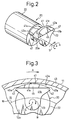
- an inclined guide surface 45 is provided in the piston side rotation restricting member 41, so that a wedge-shaped space directed (converged) in the direction of axis S of the piston 20 is formed between the inclined guide surface 45 and the contact engaging surface 43a of the housing side rotation restricting member 43. Accordingly, when the piston 20 is reciprocated, a wedge action occurs between the inclined guide surface 45 and the contact engaging surface 43a, and a quantity of lubricant in the crank chamber 15 including portion, which would be otherwise pushed away by the end surface 41b of the neck portion 23 if the inclined guide surface 45 is not provided, can be taken into the wedge-shaped space and introduced into a gap between the rotation restricting members 41, 43.
- the inclined guide surface 45 is formed as a single flat surface in such a manner that the end surface 41b on the side opposite to the head portion 22 of the piston side rotation restricting member 41 is cut off to the great extent.
- the piston side rotation restricting member 41 is formed in such a convex shape that the central portion thereof is higher than the side portions and, as clearly shown in Fig. 2 and 4, the ridge line of the inclined guide surface 45 approaches the other end surface 41c as the position approaches the center. Accordingly, as shown in Fig. 4, the inclined guide surface 45 collects the lubricant to the center and introduces it into a gap between the rotation restricting members 41 and 43, only when the piston 20 is moved from the top dead center to the bottom dead center in the reciprocating motion of the piston 20 (the suction stroke).
- the arrow D shows the movement of the piston in the suction stroke.
- an abrasion-resistant coating C is formed on the contact engaging surfaces 42a and the connecting surface 41a of the piston side rotation restricting member 41.
- the abrasion-resistant coating C is made of a fluoro resin such as PTFE (polytetrafluoroethylene) as a solid lubricant.
- PTFE polytetrafluoroethylene
- the thickness of the abrasion-resistant coating C is 20 ⁇ m to 40 ⁇ m.
- Lubricant is supplied into the crank chamber 15, along with refrigerant gas which is delivered through the cylinder bores 12a as a blow-by gas or through the supply passage 33, in addition to the lubricant initially supplied into the crank chamber 15.
- the lubricant existing in the crank chamber 15 in this way is effectively taken into a gap between the piston side rotation restricting member 41 and the housing side rotation restricting member 43 by the action of the inclined guide surface 45 caused by the reciprocating motion of the piston 20 as described above. Therefore, it is possible to accomplish an effective fluid lubrication between the rotation restricting members 41 and 43, especially between the contact engaging surfaces 42a and 43a. That is, it is possible to conduct a low frictional sliding motion between the contact engaging surfaces 42a and 43a.
- the lubricant existing in the crank chamber 15 flows to the outside of the crank chamber 15 together with the refrigerant gas via the extraction passage 34, and an absolute quantity of lubricant in the crank chamber 15 is decreased in some cases, due to the relationship of the incoming lubricant supplied by blow-by gas or through the supply passage 33 and the extracted lubricant.
- the primary lubrication conducted between the piston side rotation restricting member 41 and the housing side rotation restricting member 43 is ensured by the solid lubrication conducted by abrasion-resistant coating C, rather than liquid lubrication conducted by lubricant, so a low frictional sliding motion can be maintained between the piston side rotation restricting member 41 and the housing side rotation restricting member 43.
- Figs. 5 to 6B are views showing the second embodiment of the present invention.
- the central region of the inclined guide surface 45 is composed of a flat surface. That is, the inclined guide surface 45 is formed in such a manner that only the central region (corresponding to the position of the connecting surface 41a between the contact engaging surfaces 42a) is greatly cut in the end surface 41b of the piston side rotation restricting member 41, and guide walls 46 are formed on both sides of the inclined guide surface 45 so as to upwardly extend from this inclined surface 45. Therefore, the entire profile of the inclined guide surface 45 is formed into a recessed shape.
- This embodiment can provide the same effect as that of the first embodiment described above.
- the inclined guide surface 45 and 46 is formed into a recessed shape, so it is possible to positively prevent lubricant, which is guided to a gap between the piston side rotation restricting member 41 and the housing side rotation restricting member 43, from leaking out to both sides of the inclined guide surface 45 (wedge-shaped space). Accordingly, lubricant can be positively supplied to a gap between both the rotation restricting members 41 and 43.
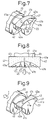
- Figs. 7 and 8 are views showing the third embodiment of the present invention.
- the inclined guide surface 45 is composed of a plurality of flat surfaces (two flat surfaces) 47 which are arranged symmetrically with respect to the axis S of the piston 20 and not arranged in the same plane, and the flat surfaces 47 are connected to each other at a merging bottom line 47b, so that the entire profile of the inclined guide surface 45 is formed into a recessed shape.
- This embodiment can provide the same effect as that of the second embodiment described above.
- the fourth embodiment is shown in Fig. 9.
- the inclined guide surface 45 is formed in the end surface 41c of the piston side rotation restricting member 41 on the side of the head portion 22. Accordingly, only when the inclined guide surface 45 is moved from the bottom dead center position to the top dead center position in the reciprocating motion of the piston 20, as shown the arrow E, that is, only in the compression and the discharge stroke, does the inclined guide surface 45 effectively introduce lubricant into a gap between the piston side rotation restricting member 41 and the housing side rotation restricting member 43.
- the fifth embodiment is shown in Fig. 10.
- the rotation restricting structure of the piston 20 is different from that of the first embodiment. That is, a pair of through-bolts 51 pass through the crank chamber 15 near the neck portion 23 of the piston 20. These through-bolts 51 compose the housing side rotation restricting member.
- rotation of the piston 20 around its own axis S is restricted when the contact engaging surface 42a of the contact engaging member 42 comes into contact with the outer circumferential surface 51a of the bolt which is a contact engaging surface of the bolt 51.
- Inclined guide surfaces 45 are arranged on the end surface 41b of the piston side rotation restricting member 41 at circumferentially opposite sides.
- a sufficiently large quantity of lubricant can be supplied from the crank chamber to between the piston side rotation restricting section and the housing side rotation restricting section. Therefore, an effective fluid lubrication can be accomplished between both the sliding rotation restricting sections.
Abstract
Description
- The present invention relates to a compressor, for compressing a refrigerant gas, which can be applied to, for example, an air-conditioner incorporated in a vehicle. More particularly, the present invention relates to compressor having, a piston rotation restricting structure for restricting rotation of a piston around the axis of the piston itself.
- A compressor of the above type will be explained as follows. A crank chamber is formed in a housing, and a drive shaft extends through the crank chamber and is rotatably supported by the housing. A swash plate is connected to the drive shaft in the crank chamber so that the swash plate can be rotated with the drive shaft. Cylinder bores are formed in the cylinder block composing a portion of the housing. The piston has a head portion and a neck portion which are axially connected with each other. The head portion of the piston is inserted in the cylinder bore, and the neck portion of the piston is located in the crank chamber outside the cylinder bore. Shoes are housed in this neck portion. The piston is connected to the swash plate via the shoes. Rotation of the swash plate caused by rotation of the drive shaft is converted into a reciprocating motion of the piston via the shoes. Therefore, refrigerant gas is compressed in the cylinder bore.
- In the compressor constructed as described above, since the piston is connected to the swash plate via the shoes, and the piston tends to rotate around the axis of the piston itself, vibration and noise are possibly caused by the interference of the neck portion of the piston with the swash plate which rotates at high speed. Therefore, a piston rotation restricting structure is provided in the above compressor. That is, a piston side rotation restricting member is arranged in the neck portion of the piston. A housing side rotation restricting member is provided in the housing at the crank chamber to engage with the piston side rotation restricting member while allowing reciprocating motion of the piston. Rotation of the piston around the axis of the piston itself is restricted by the engagement of the piston side rotation restricting member with the housing side rotation restricting member.
- However, when the above rotation restricting structure is provided, a new problem is caused in which the number of sliding portions between the piston and the housing is increased, that is, a sliding portion, between both the rotation restricting sections, is newly added to the number of the sliding portions. Therefore, power loss caused in the compressor is increased. In order to solve the above problem, there is proposed, as a countermeasure, to form an abrasion-resistant coating, for example, on the piston side rotation restricting member. However, even if an abrasion-resistant coating is provided, it has a problem of durability that it will be worn out by the repetition of sliding motion between the piston side rotation restricting member and the housing side rotation restricting member.
- In this case, the crank chamber is supplied with refrigerant gas which enters the crank chamber, for example, as blow-by gas. This refrigerant gas contains mist of lubricant. If the supplied lubricant into the crank chamber can be supplied to a gap between the piston side rotation restricting member and the housing side rotation restricting member, fluid lubrication can be effectively accomplished between both sliding rotation restricting members. However, the lubricant supplied into the crank chamber is pushed back by the end surface of the neck portion of the reciprocating piston. Therefore, only a small quantity of lubricant enters a gap between both rotation restricting members.
- The present invention is accomplished to solve the above problems of the prior art. It is an object of the present invention to provide a compressor having a piston rotation restricting structure capable of supplying a sufficiently large quantity of lubricant from the crank chamber to a gap between the piston side rotation restricting member and the housing side rotation restricting member.
- In order to accomplish the above object, according to the present invention, there is provided a compressor comprising: a housing having cylinder bores and a crank chamber; pistons having head portions and neck portions arranged such that the head portions are reciprocatingly inserted in the cylinder bores and the neck portions connected to the head portions; a drive shaft extending through the crank chamber and rotatably supported by the housing; a cam plate such as a swash plate arranged in the crank chamber and rotatable with the drive shaft; shoes arranged between the cam plate and the neck portions of the pistons; a piston rotation restricting structure comprising a first rotation restricting member formed on the neck portion of each piston, and a second rotation restricting member provided in the housing so that the first rotation restricting member can contact the second rotation restricting member to restrict rotation of the piston about its own axis while allowing reciprocating motion of the piston; the first rotation restricting member comprising axially spaced end surfaces, and an outer peripheral surface between the end surfaces; and an inclined guide surface formed in one end surface of the first rotation restricting member and inclined toward the outer peripheral surface for guiding lubricant from the crank chamber into a gap between the first rotation restricting member and the second rotation restricting member when the piston moves in one direction or in the other direction.
- In this compressor, lubricant is introduced from the crank chamber into the inclined guide surface by the reciprocating motion of the piston and supplied to a gap between the first rotation restricting member and the second rotation restricting member. Accordingly, it is possible to supply a sufficiently large quantity of lubricant to a gap between the first rotation restricting member and the second rotation restricting member. Accordingly, fluid lubrication can be effectively accomplished between both sliding rotation restricting members.
- Preferably, the inclined guide surface comprises a single flat surface. When this structure is adopted, the inclined guide surface can be easily machined.
- Preferably, the inclined guide surface comprises a flat surface and guide walls provided on both sides of the flat surface so that the entire inclined guide surface is formed into a recessed shape. Preferably, the entire inclined guide surface is formed into a recessed shape in which a plurality of flat surfaces, which are arranged in parallel to the axis of the piston and are connected with each other at a merging bottom line. Preferably, the inclined guide surface is composed of a concavity on which the central portion is deeper than both the side portions.
- According to the above structure, most of the lubricant introduced into the inclined guide surface by the reciprocating motion of the piston is prevented, by the inclined guide surface which is formed into a recessed shape, from leaking out onto the sides. Therefore, the lubricant can be positively supplied to both the rotation restricting members.
- Preferably, an abrasion-resistant coating is provided on at least one of an engaging surface of the first and second rotation restricting members.
- According to the above structure, even when an absolute quantity of lubricant in the crank chamber is small so that a sufficiently effective fluid lubrication cannot be accomplished between both the rotation restricting members, the first and second rotation restricting members can slide on each other with a low friction coefficient by solid lubrication conducted by the abrasion-resistant coating. On the contrary, when an absolute quantity of lubricant in the crank chamber is large, a sufficiently large quantity of lubricant can be supplied to a gap between both the rotation restricting members by the inclined guide surface. Therefore, the main lubrication between both the rotation restricting members changes from solid lubrication conducted by the abrasion-resistant coating to fluid lubrication conducted by lubricant, and at the same time, the abrasion-resistant coating is protected by the fluid lubrication. Therefore, the durability can be enhanced.
- Preferably, the inclined guide surface is formed on one end face of the first rotation restricting member located on the side opposite to the head portion.
- In the above structure, the inclined guide surface of the piston can be easily performed, for example, finish grinding can be easily conducted on the inclined guide surface, because one end face opposed to the head portion of the first rotation restricting member is a terminal end face of the piston part and the inclined guide surface can be easily machined here. However, one end face on the side of the head portion of the first rotation restricting member is located in the middle of the piston part in the axial direction. Therefore, it is difficult to conduct machining of the inclined guide surface on this face.
- Preferably, one arrangement of the second rotation restricting member which is desirable at present is realized. Thus, the second rotation restricting member comprises an inner peripheral surface of the housing surrounding the crank chamber around the drive axis.
- The present invention will become more apparent from the following description of the preferred embodiments, with reference to the accompanying drawings, in which:
- Fig. 1 is a longitudinally cross-sectional view of a single headed piston type, variable capacity compressor;
- Fig. 2 is a perspective view of the piston of Fig. 1;
- Fig. 3 is a rear view of the piston, with a portion of the housing;
- Fig. 4 is a plan view of a portion of the piston including the neck portion;
- Fig. 5 is a perspective view of a portion of the piston including the neck portion of the second embodiment;
- Fig. 6A is a plan view of a portion of the piston including the neck portion of Fig. 5;
- Fig. 6B is a cross-sectional view of the portion of the piston of Fig. 6A;
- Fig. 7 is a perspective view of a portion of the piston including the neck portion of the third embodiment;
- Fig. 8 is a plan view of a portion of the piston including the neck portion of Fig. 7;
- Fig. 9 is a perspective view of a portion of the piston including the neck portion of the fourth embodiment; and
- Fig. 10 is a rear view of the piston of the fifth embodiment, with a portion of the housing.
-
- The present invention will now be described with reference to the first to fifth embodiments in which the present invention is realized as a single headed piston type, variable capacity compressor which is applied to an air-conditioner for vehicle. In this connection, concerning the second to the fifth embodiments, only points different from the points of the first embodiment will be explained, and like reference characters are used to indicate like parts and repeated explanations are omitted.
- Figs. 1 to 4 show the first embodiment of the present invention. As shown in Fig. 1, a
front housing 11 made of metallic aluminum material is joined to the front end of acylinder block 12 as a center housing, and arear housing 13 is joined to the rear end of thecylinder block 12 via a valve and port formingplate assembly 14. Thesehousing members 11 to 13 are fastened and fixed to each other by a plurality of through-bolts 51 which extend through these housing members (only one through-bolt is schematically shown in the drawing). Thefront housing 11, thecylinder block 12 and therear housing 13 constitute a housing assembly of the variable capacity compressor. - A
crank chamber 15 is defined in thefront housing 11 and thecylinder block 12. Adrive shaft 16 is rotatably supported by thefront housing 11 and thecylinder block 12 in such a manner that thedrive shaft 16 extends through thecrank chamber 15. Although not shown in the drawing, thedrive shaft 16 is connected to a vehicle engine as an external drive source, via a clutch mechanism such as an electromagnetic clutch. Accordingly, thedrive shaft 16 is driven by the vehicle engine when the clutch mechanism is turned on while the engine is operating. - A rotary support body 17 is attached to the
drive shaft 16 in thecrank chamber 15. Aswash plate 18, which functions as a cam plate, is tiltably supported by thedrive shaft 16. Ahinge mechanism 19 is interposed between the rotary support body 17 and theswash plate 18. Theswash plate 18 can be rotated with thedrive shaft 16 by the hinge connection between theswash plate 18 and the rotary support body 17 via thehinge mechanism 19. At the same time, theswash plate 18 can be tilted with respect to thedrive shaft 16. - A plurality of cylinder bores 12a are formed in the
cylinder block 12 around an axis L of the drive shaft 16 (only onecylinder bore 12a is shown in the drawing). Single headedtype pistons 20 are arranged in the cylinder bores 12a. Thepiston 20 is connected to theswash plate 18 via shoes 21. Accordingly, a rotary motion of thedrive shaft 16 is converted into a reciprocating motion of thepistons 20 in the cylinder bores 12a via theswash plate 18 and the shoes 21. - A
suction chamber 27 and adischarge chamber 28 are respectively defined in therear housing 13.Suction ports 29,suction valves 30,discharge ports 31 anddischarge valves 32 are respectively formed in the valve and port formingplate assembly 14. Refrigerant gas is sucked from thesuction chamber 27 into the cylinder bore 12a via thesuction port 29 and thesuction valve 30 when thepiston 20 is moved (in the one direction) from the top dead center position to the bottom dead center position. Refrigerant gas sucked in thecylinder bore 12a is compressed to a predetermined pressure when thepiston 20 is moved (in the opposite direction) from the bottom dead center position to the top dead center position. After that, the compressed refrigerant gas is discharged into thedischarge chamber 28 via thedischarge port 31 and thedischarge valve 32. - A
supply passage 33 connects thedischarge chamber 28 to the crankchamber 15. Anextraction passage 34 connects thecrank chamber 15 to thesuction chamber 27. Acapacity control valve 35 is arranged in thesupply passage 33. A pressuresensitive passage 36 connects thesuction chamber 27 to thecapacity control valve 35. Thecapacity control valve 35 includes adiaphragm 35a, which is a pressure sensitive member, and avalve body 35b connected to thediaphragm 35a. - The capacity control valve operates the
valve body 35b, so that the degree of opening of thesupply passage 33 can be changed when thediaphragm 35a reacts to the suction pressure of thesuction chamber 27 introduced through the pressuresensitive passage 36. When the degree of opening of thesupply passage 33 is changed, the amount of refrigerant gas introduced into thecrank chamber 15 is changed, and according to the relationship with the amount of refrigerant gas which is released to thesuction chamber 27 via theextraction passage 34, the pressure in thecrank chamber 15 is changed. Accordingly, a difference between the pressure in thecrank chamber 15 and the pressure in the cylinder bore 12a via thepiston 20 is changed, and an inclination angle of theswash plate 18 is changed as shown by two-dotted chain lines in Fig. 1. As a result, a stroke of thepiston 20 is changed, and a discharge capacity of the compressor is adjusted. - Next, the structure of the
piston 20 and the rotation restricting structure of thepiston 20 will be described below in detail. - As shown in Figs. 1 and 2, the
piston 20 has acylindrical head portion 22, which is inserted in thecylinder bore 12a, and aneck portion 23, which is located in thecrank chamber 15 outside thecylinder bore 12a, these portions being integrally connected with each other in the direction of an axis S. Thehead portion 22 and theneck portion 23 are made of metallic aluminum material. A pair ofshoe seats 23a are arranged in theneck portion 23. A pair of shoes 21 are provided in theneck portion 23 and respectively received by the pair ofshoe seats 23a by means of spherical contact. A front surface and a back surface of the outer periphery of theswash plate 18 are slidably interposed between the pair of shoes 21. - As shown in Figs. 2 and 3, a first piston side
rotation restricting member 41 is provided in theneck portion 23 of thepiston 20. The piston siderotation restricting member 41 has a pair ofcontact engaging portions 42 projecting to the leading side and the trailing side in the rotational direction of theswash plate 18. Contact engagingsurfaces 42a on thepiston 20 are formed as the outer peripheral surface of the piston siderotation restricting member 41 at thecontact engaging portions 42, opposed to thecircumferential wall 43 of thefront housing 11 in thecrank chamber 15. Thecircumferential wall 43 of thefront housing 11 constitutes a second, housing siderotation restricting member 43. In this housing siderotation restricting member 43, an innerperipheral surface 43a, which is a circular arcuate concave surface formed around the axis L of thedrive shaft 16, forms acontact engaging surface 43a on the housing side. Connectingsurface 41a of the piston siderotation restricting member 41 is provided between both thecontact engaging portions 42, and thecontact engaging surfaces 42a of both thecontact engaging portions 42 are connected to each other via the connectingsurface 41a. Both thecontact engaging surfaces 42a and the connectingsurface 41a are arranged on the common arcuate convex surface, so that they can be easily machined with respect to thepiston 20. That is, by only rotating thepiston 20 around the axis of the arcuate convex surface under the condition that a polishing tool is set at a fixed position, thesurfaces contact engaging surface 43a on the housing side. - As shown by the arrows A and B in Fig. 3, due to the connecting structure of the
piston 20 with theswash plate 18 via the shoes 21, thepiston 20 tends to rotate around its own axis S. The arrow A shows the rotational direction of theswash plate 18, and the arrow B shows the possible rotational direction of thepiston 20. Accordingly, when thepiston 20 receives an external force for some reason, it may be rotated around its axis S. When the shoes 21 slide on theswash plate 18, the shoes 21 are apt to be rotated in the same rotational direction as that of theswash plate 18, that is, the shoes 21 are rotated clockwise in the drawing. That is, due to a difference between the circumferential speed of theswash plate 18 at a radially outer position and that at a radially inner position, with the former being higher than the latter, the shoes 21 are given a rotational force in the same direction as that of the rotational direction of theswash plate 18. Therefore, when the compressor is operated, thepiston 20 tends to rotate in the same direction as that of the rotational direction of theswash plate 18 by the rotational force of theswash plate 18 given to it via the shoes 21. - However, the rotation of the
piston 20 in the same direction as that of the rotational direction of theswash plate 18 is restricted, by engaging thecontact engaging surface 42a of one contact engaging portion 42 (on the left in Fig. 3) of the piston siderotation restricting member 41 with thecontact engaging surface 43a of the housing siderotation restricting member 43, and rotation of thepiston 20 in the direction opposite to the rotational direction of theswash plate 18 is restricted by engaging thecontact engaging surface 42a of the other contact engaging portion 42 (on the right in Fig. 3) with thecontact engaging surface 43a of the housing siderotation restricting member 43. Accordingly, for example, a portion of thepiston 20 close to theneck portion 23 does not interfere with theswash plate 18. Therefore, it is possible to prevent occurrence of vibration and noise caused by interference of thepiston 20 with theswash plate 18 rotating at high speed. - Next, characteristics of this embodiment will be explained below.
- The provision of the above rotation restricting structure of the
piston 20 causes a new problem, in which the number of sliding portions between thepiston 20 and thehousing 11 to 13 is increased, that is, the number of sliding portions between both therotation restricting members crank chamber 15 is sufficiently supplied to a gap between therotation restricting members rotation restricting members - That is, in order to move the lubricant existing in the
crank chamber 15 to a gap between therotation restricting members rotation restricting members piston 20, is used. However, as described in the description of the prior art, in this structure, most of lubricant is pushed away by the end faces 41b and 41c of theneck portion 23, and it is difficult to supply a sufficiently large quantity of lubricant to a gap between therotation restricting members - Therefore, as shown in Figs. 1 to 4, an
inclined guide surface 45 is provided in the piston siderotation restricting member 41, so that a wedge-shaped space directed (converged) in the direction of axis S of thepiston 20 is formed between theinclined guide surface 45 and thecontact engaging surface 43a of the housing siderotation restricting member 43. Accordingly, when thepiston 20 is reciprocated, a wedge action occurs between theinclined guide surface 45 and thecontact engaging surface 43a, and a quantity of lubricant in thecrank chamber 15 including portion, which would be otherwise pushed away by theend surface 41b of theneck portion 23 if theinclined guide surface 45 is not provided, can be taken into the wedge-shaped space and introduced into a gap between therotation restricting members - The
inclined guide surface 45 is formed as a single flat surface in such a manner that theend surface 41b on the side opposite to thehead portion 22 of the piston siderotation restricting member 41 is cut off to the great extent. The piston siderotation restricting member 41 is formed in such a convex shape that the central portion thereof is higher than the side portions and, as clearly shown in Fig. 2 and 4, the ridge line of the inclined guide surface 45 approaches theother end surface 41c as the position approaches the center. Accordingly, as shown in Fig. 4, theinclined guide surface 45 collects the lubricant to the center and introduces it into a gap between therotation restricting members piston 20 is moved from the top dead center to the bottom dead center in the reciprocating motion of the piston 20 (the suction stroke). The arrow D shows the movement of the piston in the suction stroke. - As illustrated by dots in Figs. 2 and 4, an abrasion-resistant coating C is formed on the
contact engaging surfaces 42a and the connectingsurface 41a of the piston siderotation restricting member 41. The abrasion-resistant coating C is made of a fluoro resin such as PTFE (polytetrafluoroethylene) as a solid lubricant. For example, the thickness of the abrasion-resistant coating C is 20 µm to 40 µm. - Lubricant is supplied into the
crank chamber 15, along with refrigerant gas which is delivered through the cylinder bores 12a as a blow-by gas or through thesupply passage 33, in addition to the lubricant initially supplied into thecrank chamber 15. - The lubricant existing in the
crank chamber 15 in this way is effectively taken into a gap between the piston siderotation restricting member 41 and the housing siderotation restricting member 43 by the action of theinclined guide surface 45 caused by the reciprocating motion of thepiston 20 as described above. Therefore, it is possible to accomplish an effective fluid lubrication between therotation restricting members contact engaging surfaces contact engaging surfaces - However, the lubricant existing in the
crank chamber 15 flows to the outside of thecrank chamber 15 together with the refrigerant gas via theextraction passage 34, and an absolute quantity of lubricant in thecrank chamber 15 is decreased in some cases, due to the relationship of the incoming lubricant supplied by blow-by gas or through thesupply passage 33 and the extracted lubricant. In this case, the primary lubrication conducted between the piston siderotation restricting member 41 and the housing siderotation restricting member 43 is ensured by the solid lubrication conducted by abrasion-resistant coating C, rather than liquid lubrication conducted by lubricant, so a low frictional sliding motion can be maintained between the piston siderotation restricting member 41 and the housing siderotation restricting member 43. - The following effects can be provided by this embodiment.
- (1) By the provision of the
inclined guide surface 45, it is possible to accomplish an effective fluid lubrication between the piston siderotation restricting member 41 and the housing siderotation restricting member 43, that is, it is possible to accomplish a low frictional sliding motion between the piston siderotation restricting member 41 and the housing siderotation restricting member 43. Accordingly, even if the rotation restricting structure of thepiston 20 is provided, an increase in power loss of the compressor can be reduced, and thus, it is possible to reduce a load given to the engine. Also, the provision of theinclined guide surface 45 formed in thepiston 20 means that a portion of the material of thepiston 20 is taken away, so the weight of thepiston 20 is lightened at the same time. In order to enhance this effect of reducing the weight, it is necessary to increase the size of theinclined guide surface 45 as much as possible. - (2) The flat
inclined guide surface 45 can be easily machined, and the manufacturing cost of thepiston 20 can be reduced. - (3) The abrasion-resistant coating C is formed on
the
contact engaging surface 42a of the piston siderotation restricting member 41. Accordingly, even if an absolute quantity of lubricant in thecrank chamber 15 is small and an effective fluid lubrication cannot be expected between therotation restricting members rotation restricting members crank chamber 15 is large and an effective fluid lubrication is accomplished between the piston siderotation restricting member 41 and the housing siderotation restricting member 43, abrasion-resistant coating C is protected by this fluid lubricant and therefore, abrasion-resistant coating C can be used over a long period of time. - (4) The
inclined guide surface 45 is formed in theend surface 41b located on the side opposite to thehead portion 22 in the piston siderotation restricting member 41. Accordingly, machining of theinclined guide surface 45 of thepiston 20 can be easily performed, for example, finish grinding can be easily conducted to form theinclined guide surface 45, because theend surface 41b opposite to thehead portion 22 of the piston siderotation restricting member 41 is a terminal end surface of thepiston 20 and the inclined guide face 45 can be easily machined. However, theend surface 41c of the piston siderotation restricting member 41 on the side of thehead portion 22 is located in the middle of the piston part in the direction of axis S, and it is difficult to conduct machining of theinclined guide surface 45. - (5) In the variable capacity type compressor, the
capacity can be changed by adjusting the pressure in the
crank chamber 15. That is, thecrank chamber 15 is a pressure control chamber used for adjusting the discharge capacity, and thecrank chamber 15 does not exist in the refrigerant circulating circuit composing a refrigerating cycle of an air-conditioner for vehicle use. Accordingly, it is impossible to expect that a large quantity of refrigerant gas containing lubricant flows in thecrank chamber 15. The fact that the structure for supplying lubricant positively to a gap between therotation restricting members 41 and 43 (inclined guide surface 45) is applied to the crankchamber 15 which is put into such a severe lubricating condition, can provide a particularly good effect. -
- Figs. 5 to 6B are views showing the second embodiment of the present invention. In this embodiment, the central region of the
inclined guide surface 45 is composed of a flat surface. That is, theinclined guide surface 45 is formed in such a manner that only the central region (corresponding to the position of the connectingsurface 41a between thecontact engaging surfaces 42a) is greatly cut in theend surface 41b of the piston siderotation restricting member 41, and guidewalls 46 are formed on both sides of theinclined guide surface 45 so as to upwardly extend from thisinclined surface 45. Therefore, the entire profile of theinclined guide surface 45 is formed into a recessed shape. - This embodiment can provide the same effect as that of the first embodiment described above. Further, the
inclined guide surface rotation restricting member 41 and the housing siderotation restricting member 43, from leaking out to both sides of the inclined guide surface 45 (wedge-shaped space). Accordingly, lubricant can be positively supplied to a gap between both therotation restricting members - Figs. 7 and 8 are views showing the third embodiment of the present invention. In this embodiment, the
inclined guide surface 45 is composed of a plurality of flat surfaces (two flat surfaces) 47 which are arranged symmetrically with respect to the axis S of thepiston 20 and not arranged in the same plane, and theflat surfaces 47 are connected to each other at a mergingbottom line 47b, so that the entire profile of theinclined guide surface 45 is formed into a recessed shape. - This embodiment can provide the same effect as that of the second embodiment described above.
- The fourth embodiment is shown in Fig. 9. In this embodiment, the
inclined guide surface 45 is formed in theend surface 41c of the piston siderotation restricting member 41 on the side of thehead portion 22. Accordingly, only when theinclined guide surface 45 is moved from the bottom dead center position to the top dead center position in the reciprocating motion of thepiston 20, as shown the arrow E, that is, only in the compression and the discharge stroke, does theinclined guide surface 45 effectively introduce lubricant into a gap between the piston siderotation restricting member 41 and the housing siderotation restricting member 43. - In this embodiment, it is possible to provide the same effect as that of the first embodiment except for item (4).
- The fifth embodiment is shown in Fig. 10. In this embodiment, the rotation restricting structure of the
piston 20 is different from that of the first embodiment. That is, a pair of through-bolts 51 pass through thecrank chamber 15 near theneck portion 23 of thepiston 20. These through-bolts 51 compose the housing side rotation restricting member. As shown by two-dotted chain lines in the drawing, rotation of thepiston 20 around its own axis S is restricted when thecontact engaging surface 42a of thecontact engaging member 42 comes into contact with the outercircumferential surface 51a of the bolt which is a contact engaging surface of thebolt 51. Inclined guide surfaces 45 are arranged on theend surface 41b of the piston siderotation restricting member 41 at circumferentially opposite sides. - In this embodiment, it is possible to provide the same effect as that of the first embodiment.
- In this connection, it is possible to adopt the following embodiment without departing from the spirit and scope of the present invention.
- In the first embodiment described above, the
inclined guide surface 45 is formed into a concave shape in which the center thereof is deeper than both sides thereof. Due to the foregoing, most of lubricant which enters the wedge-shaped space is moved to the central side having a sufficiently large space. In other words, lubricant does not leak out from the inclined guide surface 45 (wedge-shaped space) to either sides. Accordingly, lubricant can be effectively introduced into a gap between therotation restricting members - For example, the first and the fourth embodiments
can be combined with each other. That is, the inclined
guide surfaces 45 are formed in the
end surface 41b on the side opposite to thehead portion 22 of the piston siderotation restricting member 41 and in theend surface 41c on the side of thehead portion 22. Due to the above arrangement, in the suction stroke and the compression stroke in the reciprocating motion of thepiston 20, lubricant can be effectively introduced into a gap between both therotation restricting members - An abrasion-resistant coating C is formed on the
contact engaging surface 43a of the housing siderotation restricting member 43. In this case, as described in each embodiment described above, the abrasion-resistant coating may be formed or may not be formed on thecontact engaging surface 42a of the piston siderotation restricting member 43. - It is possible to adopt a piston rotation
restricting mechanism of the present invention to a fixed
capacity type compressor, in which the
swash plate 18 is fixed to thedrive shaft 16 and the inclination angle of the swash plate is kept constant. - It is possible to adopt an embodiment having a
piston rotation restricting structure of a double headed
piston type compressor in which two
head portions 22 are provided on both sides of theneck portion 23. - It is possible to adopt an embodiment in which a cam plate is changed from the swash plate to a wave cam in the above described fixed capacity type compressor.
- According to the present invention, the structure of which is described above, a sufficiently large quantity of lubricant can be supplied from the crank chamber to between the piston side rotation restricting section and the housing side rotation restricting section. Therefore, an effective fluid lubrication can be accomplished between both the sliding rotation restricting sections.
Claims (14)
- A compressor comprising:a housing having cylinder bores and a crank chamber;pistons having head portions and neck portions arranged such that said head portions are reciprocatingly inserted in said cylinder bores and said neck portions are connected to said head portions;a drive shaft extending through said crank chamber and rotatably supported by said housing;a cam plate arranged in said crank chamber and rotatable with said drive shaft;shoes arranged between said cam plate and said neck portions of said pistons;a piston rotation restricting structure comprising a first rotation restricting member formed on said neck portion of each piston, and a second rotation restricting member provided in said housing so that said first rotation restricting member can contact said second rotation restricting member to restrict rotation of said piston about its own axis while allowing a reciprocating motion of said piston;said first rotation restricting member comprising axially spaced end surfaces, and an outer peripheral surface between said end surfaces; andan inclined guide surface formed in one end surface of said first rotation restricting member and inclined toward said outer peripheral surface for guiding lubricant from the crank chamber into a gap between said first rotation restricting member and said second rotation restricting member when said piston moves in one direction or in the other direction.
- A compressor according to claim 1, wherein said inclined guide surface comprises a single flat surface.
- A compressor according to claim 1, wherein said inclined guide surface comprises a flat surface and guide wall surfaces provided on both sides of the flat surface so that the inclined guide surface as a whole is formed into a recessed shape.
- A compressor according to claim 1, wherein said inclined guide surface comprises a plurality of flat surfaces arranged symmetrically with respect to an axis of the piston and connected with each other at a merging bottom line so that the entire inclined guide surface is formed into a recessed shape.
- A compressor according to claim 1, wherein the inclined guide surface comprises a concave surface having a central portion and side portions, said central portion being deeper than both side portions.
- A compressor according to claim 1, wherein an abrasion-resistant coating is provided on at least one of an engaging surface of the first and second rotation restricting members.
- A compressor according to claim 1, wherein said inclined guide surface is formed on one end surface of the first rotation restricting member located on the side opposite to the head portion.
- A compressor according to claim 1, wherein said inclined guide surface is formed on one end surface of the first rotation restricting member located on the side of the head portion.
- A compressor according to claim 1, wherein said second rotation restricting member comprises an inner peripheral surface of the housing surrounding the crank chamber.
- A compressor according to claim 9, wherein said outer peripheral surface of said first rotation restricting member has circumferentially spaced end portions designed such that one of said end portions can contact the inner peripheral surface of said housing when said piston is rotated.
- A compressor according to claim 10, wherein said outer peripheral surface of said first rotation restricting member is formed by a circular arcuate surface having a radius of curvature greater than a radius of curvature of the piston and smaller than a radius of curvature of the inner peripheral surface of the housing.
- A compressor according to claim 10, wherein end regions of said outer peripheral surface of said first rotation restricting member including said end portions are directly connected to said one end surface of said first rotation restricting member, and the remaining region of said outer peripheral surface of said first rotation restricting member between said end regions is connected to said one end surface of said first rotation restricting member via said inclined guide surface.
- A compressor according to claim 1, wherein said housing includes a plurality of housing parts joined together by bolts, and said second rotation restricting member comprises said bolts.
- A compressor according to claim 1, wherein said inclined guide surface is shaped such that lubricant is guided toward a center of said inclined guide surface.
Applications Claiming Priority (2)
| Application Number | Priority Date | Filing Date | Title |
|---|---|---|---|
| JP28987199A JP3925007B2 (en) | 1999-10-12 | 1999-10-12 | Piston rotation restriction structure in a compressor |
| JP28987199 | 1999-10-12 |
Publications (3)
| Publication Number | Publication Date |
|---|---|
| EP1092872A2 true EP1092872A2 (en) | 2001-04-18 |
| EP1092872A3 EP1092872A3 (en) | 2004-01-28 |
| EP1092872B1 EP1092872B1 (en) | 2006-12-20 |
Family
ID=17748852
Family Applications (1)
| Application Number | Title | Priority Date | Filing Date |
|---|---|---|---|
| EP00121833A Expired - Lifetime EP1092872B1 (en) | 1999-10-12 | 2000-10-06 | Piston for swash plate compressor |
Country Status (7)
| Country | Link |
|---|---|
| US (1) | US6393964B1 (en) |
| EP (1) | EP1092872B1 (en) |
| JP (1) | JP3925007B2 (en) |
| KR (1) | KR100386912B1 (en) |
| CN (1) | CN1230618C (en) |
| BR (1) | BR0004763A (en) |
| DE (1) | DE60032436T2 (en) |
Families Citing this family (9)
| Publication number | Priority date | Publication date | Assignee | Title |
|---|---|---|---|---|
| WO2001025636A1 (en) * | 1999-10-04 | 2001-04-12 | Kabushiki Kaisha Toyoda Jidoshokki Seisakusho | Electric compressor |
| JP4194350B2 (en) * | 2002-11-26 | 2008-12-10 | サンデン株式会社 | Swash plate compressor |
| US20040149123A1 (en) * | 2002-12-18 | 2004-08-05 | Kiyokazu Yamamoto | Piston compressor |
| JP2004263644A (en) * | 2003-03-03 | 2004-09-24 | Toyota Industries Corp | Variable displacement compressor |
| CN100359165C (en) * | 2003-11-05 | 2008-01-02 | 上海三电贝洱汽车空调有限公司 | Spheric surface against rotation of compressor piston |
| US7802512B2 (en) | 2007-02-07 | 2010-09-28 | Doowon Technical College | Assembly structure of drive shaft and swash plate in swash plate type compressor |
| KR101402760B1 (en) * | 2007-11-27 | 2014-06-11 | 주식회사 두원전자 | Piston of Compressor Swash Plate |
| CN102310336B (en) * | 2011-08-25 | 2013-08-07 | 桐乡市易锋机械厂 | Processing method of rotating-proof surfaces of pistons |
| JP5492917B2 (en) * | 2012-02-01 | 2014-05-14 | 株式会社豊田自動織機 | Variable capacity swash plate compressor |
Citations (7)
| Publication number | Priority date | Publication date | Assignee | Title |
|---|---|---|---|---|
| JPH08109874A (en) * | 1994-10-11 | 1996-04-30 | Calsonic Corp | Swash plate compressor |
| EP0740076A2 (en) * | 1995-04-13 | 1996-10-30 | Calsonic Corporation | Variable displacement swash plate type compressor |
| EP0819849A2 (en) * | 1996-07-15 | 1998-01-21 | Kabushiki Kaisha Toyoda Jidoshokki Seisakusho | Piston for compressors |
| EP0819850A2 (en) * | 1996-07-15 | 1998-01-21 | Kabushiki Kaisha Toyoda Jidoshokki Seisakusho | Piston for compressors |
| EP0823552A2 (en) * | 1996-08-09 | 1998-02-11 | Kabushiki Kaisha Toyoda Jidoshokki Seisakusho | A device for guiding a piston in a compressor |
| DE19734472A1 (en) * | 1996-08-09 | 1998-03-12 | Toyoda Automatic Loom Works | Piston for compressors for motor vehicle air conditioner |
| DE19754440A1 (en) * | 1996-12-09 | 1998-06-10 | Toyoda Automatic Loom Works | Reciprocating piston compressor |
Family Cites Families (2)
| Publication number | Priority date | Publication date | Assignee | Title |
|---|---|---|---|---|
| JP2572690Y2 (en) * | 1992-09-02 | 1998-05-25 | サンデン株式会社 | Piston rotation prevention mechanism for swash plate compressor |
| JPH10196539A (en) | 1997-01-17 | 1998-07-31 | Zexel Corp | Reciprocating compressor |
-
1999
- 1999-10-12 JP JP28987199A patent/JP3925007B2/en not_active Expired - Fee Related
-
2000
- 2000-08-19 KR KR10-2000-0048049A patent/KR100386912B1/en not_active IP Right Cessation
- 2000-10-03 US US09/678,532 patent/US6393964B1/en not_active Expired - Lifetime
- 2000-10-06 DE DE60032436T patent/DE60032436T2/en not_active Expired - Lifetime
- 2000-10-06 EP EP00121833A patent/EP1092872B1/en not_active Expired - Lifetime
- 2000-10-10 BR BR0004763-5A patent/BR0004763A/en active Search and Examination
- 2000-10-12 CN CNB001309994A patent/CN1230618C/en not_active Expired - Fee Related
Patent Citations (7)
| Publication number | Priority date | Publication date | Assignee | Title |
|---|---|---|---|---|
| JPH08109874A (en) * | 1994-10-11 | 1996-04-30 | Calsonic Corp | Swash plate compressor |
| EP0740076A2 (en) * | 1995-04-13 | 1996-10-30 | Calsonic Corporation | Variable displacement swash plate type compressor |
| EP0819849A2 (en) * | 1996-07-15 | 1998-01-21 | Kabushiki Kaisha Toyoda Jidoshokki Seisakusho | Piston for compressors |
| EP0819850A2 (en) * | 1996-07-15 | 1998-01-21 | Kabushiki Kaisha Toyoda Jidoshokki Seisakusho | Piston for compressors |
| EP0823552A2 (en) * | 1996-08-09 | 1998-02-11 | Kabushiki Kaisha Toyoda Jidoshokki Seisakusho | A device for guiding a piston in a compressor |
| DE19734472A1 (en) * | 1996-08-09 | 1998-03-12 | Toyoda Automatic Loom Works | Piston for compressors for motor vehicle air conditioner |
| DE19754440A1 (en) * | 1996-12-09 | 1998-06-10 | Toyoda Automatic Loom Works | Reciprocating piston compressor |
Non-Patent Citations (1)
| Title |
|---|
| PATENT ABSTRACTS OF JAPAN vol. 1996, no. 08, 30 August 1996 (1996-08-30) -& JP 08 109874 A (CALSONIC CORP), 30 April 1996 (1996-04-30) * |
Also Published As
| Publication number | Publication date |
|---|---|
| DE60032436D1 (en) | 2007-02-01 |
| BR0004763A (en) | 2001-05-29 |
| JP3925007B2 (en) | 2007-06-06 |
| US6393964B1 (en) | 2002-05-28 |
| CN1230618C (en) | 2005-12-07 |
| EP1092872B1 (en) | 2006-12-20 |
| KR20010039832A (en) | 2001-05-15 |
| JP2001107851A (en) | 2001-04-17 |
| KR100386912B1 (en) | 2003-06-12 |
| EP1092872A3 (en) | 2004-01-28 |
| CN1292461A (en) | 2001-04-25 |
| DE60032436T2 (en) | 2007-10-04 |
Similar Documents
| Publication | Publication Date | Title |
|---|---|---|
| KR100274497B1 (en) | A compressor | |
| AU670526B2 (en) | Variable displacement piston type compressor | |
| EP0809025A1 (en) | Reciprocating pistons of piston-type compressor | |
| US5953980A (en) | Piston type compressors | |
| US5988041A (en) | Piston for compressors | |
| EP0809024B1 (en) | Reciprocating pistons of piston type compressor | |
| US6393964B1 (en) | Compressor having piston rotation restricting structure with lubricating inclined guide surface | |
| EP0881386B1 (en) | Swash plate compressor | |
| JP4439434B2 (en) | Constant velocity joint and swing swash plate compressor using the same | |
| EP0819850B1 (en) | Piston for compressors | |
| KR100274969B1 (en) | Variable displacement swash plate compressor | |
| US6293761B1 (en) | Variable displacement swash plate type compressor having pivot pin | |
| US6332394B1 (en) | Piston for swash plate type compressor, wherein head portion includes radially inner sliding projection connected to neck portion | |
| US6705204B2 (en) | Swash plate-type | |
| KR100274970B1 (en) | Variable displacement swash plate compressor | |
| JP3320587B2 (en) | Swash plate compressor | |
| US6368073B1 (en) | Swash plate compressor | |
| EP1092873A2 (en) | Cylinder bore of swash plate compressor with grooves | |
| US20090097990A1 (en) | Swash plate type compressor | |
| JP4128656B2 (en) | Swash plate compressor | |
| JPH08282256A (en) | Swash plate type compressor | |
| KR20110072317A (en) | Variable displacement swash plate type compressor | |
| KR19990006228A (en) | Variable displacement type swash plate type compressor | |
| JPH0735779U (en) | Swash plate type compressor |
Legal Events
| Date | Code | Title | Description |
|---|---|---|---|
| PUAI | Public reference made under article 153(3) epc to a published international application that has entered the european phase |
Free format text: ORIGINAL CODE: 0009012 |
|
| 17P | Request for examination filed |
Effective date: 20001006 |
|
| AK | Designated contracting states |
Kind code of ref document: A2 Designated state(s): AT BE CH CY DE DK ES FI FR GB GR IE IT LI LU MC NL PT SE |
|
| AX | Request for extension of the european patent |
Free format text: AL;LT;LV;MK;RO;SI |
|
| RAP1 | Party data changed (applicant data changed or rights of an application transferred) |
Owner name: KABUSHIKI KAISHA TOYOTA JIDOSHOKKI |
|
| PUAL | Search report despatched |
Free format text: ORIGINAL CODE: 0009013 |
|
| AK | Designated contracting states |
Kind code of ref document: A3 Designated state(s): AT BE CH CY DE DK ES FI FR GB GR IE IT LI LU MC NL PT SE |
|
| AX | Request for extension of the european patent |
Extension state: AL LT LV MK RO SI |
|
| 17Q | First examination report despatched |
Effective date: 20040604 |
|
| AKX | Designation fees paid |
Designated state(s): DE FR IT |
|
| GRAP | Despatch of communication of intention to grant a patent |
Free format text: ORIGINAL CODE: EPIDOSNIGR1 |
|
| GRAS | Grant fee paid |
Free format text: ORIGINAL CODE: EPIDOSNIGR3 |
|
| GRAA | (expected) grant |
Free format text: ORIGINAL CODE: 0009210 |
|
| AK | Designated contracting states |
Kind code of ref document: B1 Designated state(s): DE FR IT |
|
| REF | Corresponds to: |
Ref document number: 60032436 Country of ref document: DE Date of ref document: 20070201 Kind code of ref document: P |
|
| ET | Fr: translation filed | ||
| PLBE | No opposition filed within time limit |
Free format text: ORIGINAL CODE: 0009261 |
|
| STAA | Information on the status of an ep patent application or granted ep patent |
Free format text: STATUS: NO OPPOSITION FILED WITHIN TIME LIMIT |
|
| 26N | No opposition filed |
Effective date: 20070921 |
|
| PGFP | Annual fee paid to national office [announced via postgrant information from national office to epo] |
Ref country code: IT Payment date: 20131028 Year of fee payment: 14 |
|
| REG | Reference to a national code |
Ref country code: DE Ref legal event code: R082 Ref document number: 60032436 Country of ref document: DE Representative=s name: HOEGER, STELLRECHT & PARTNER PATENTANWAELTE MB, DE |
|
| PG25 | Lapsed in a contracting state [announced via postgrant information from national office to epo] |
Ref country code: IT Free format text: LAPSE BECAUSE OF NON-PAYMENT OF DUE FEES Effective date: 20141006 |
|
| REG | Reference to a national code |
Ref country code: FR Ref legal event code: PLFP Year of fee payment: 16 |
|
| PGFP | Annual fee paid to national office [announced via postgrant information from national office to epo] |
Ref country code: FR Payment date: 20150908 Year of fee payment: 16 |
|
| REG | Reference to a national code |
Ref country code: FR Ref legal event code: ST Effective date: 20170630 |
|
| PG25 | Lapsed in a contracting state [announced via postgrant information from national office to epo] |
Ref country code: FR Free format text: LAPSE BECAUSE OF NON-PAYMENT OF DUE FEES Effective date: 20161102 |
|
| PGFP | Annual fee paid to national office [announced via postgrant information from national office to epo] |
Ref country code: DE Payment date: 20180925 Year of fee payment: 19 |
|
| REG | Reference to a national code |
Ref country code: DE Ref legal event code: R082 Ref document number: 60032436 Country of ref document: DE Representative=s name: HOEGER, STELLRECHT & PARTNER PATENTANWAELTE MB, DE |
|
| REG | Reference to a national code |
Ref country code: DE Ref legal event code: R119 Ref document number: 60032436 Country of ref document: DE |
|
| PG25 | Lapsed in a contracting state [announced via postgrant information from national office to epo] |
Ref country code: DE Free format text: LAPSE BECAUSE OF NON-PAYMENT OF DUE FEES Effective date: 20200501 |