EP1669570A2 - Kühlungsanlage für eine hybride Antriebkette eines Kraftfahrzeugs - Google Patents
Kühlungsanlage für eine hybride Antriebkette eines Kraftfahrzeugs Download PDFInfo
- Publication number
- EP1669570A2 EP1669570A2 EP05300997A EP05300997A EP1669570A2 EP 1669570 A2 EP1669570 A2 EP 1669570A2 EP 05300997 A EP05300997 A EP 05300997A EP 05300997 A EP05300997 A EP 05300997A EP 1669570 A2 EP1669570 A2 EP 1669570A2
- Authority
- EP
- European Patent Office
- Prior art keywords
- temperature
- radiator
- main
- cooling
- transfer fluid
- Prior art date
- Legal status (The legal status is an assumption and is not a legal conclusion. Google has not performed a legal analysis and makes no representation as to the accuracy of the status listed.)
- Withdrawn
Links
Images


Classifications
-
- F—MECHANICAL ENGINEERING; LIGHTING; HEATING; WEAPONS; BLASTING
- F01—MACHINES OR ENGINES IN GENERAL; ENGINE PLANTS IN GENERAL; STEAM ENGINES
- F01P—COOLING OF MACHINES OR ENGINES IN GENERAL; COOLING OF INTERNAL-COMBUSTION ENGINES
- F01P7/00—Controlling of coolant flow
- F01P7/14—Controlling of coolant flow the coolant being liquid
- F01P7/16—Controlling of coolant flow the coolant being liquid by thermostatic control
- F01P7/165—Controlling of coolant flow the coolant being liquid by thermostatic control characterised by systems with two or more loops
-
- B—PERFORMING OPERATIONS; TRANSPORTING
- B60—VEHICLES IN GENERAL
- B60K—ARRANGEMENT OR MOUNTING OF PROPULSION UNITS OR OF TRANSMISSIONS IN VEHICLES; ARRANGEMENT OR MOUNTING OF PLURAL DIVERSE PRIME-MOVERS IN VEHICLES; AUXILIARY DRIVES FOR VEHICLES; INSTRUMENTATION OR DASHBOARDS FOR VEHICLES; ARRANGEMENTS IN CONNECTION WITH COOLING, AIR INTAKE, GAS EXHAUST OR FUEL SUPPLY OF PROPULSION UNITS IN VEHICLES
- B60K6/00—Arrangement or mounting of plural diverse prime-movers for mutual or common propulsion, e.g. hybrid propulsion systems comprising electric motors and internal combustion engines ; Control systems therefor, i.e. systems controlling two or more prime movers, or controlling one of these prime movers and any of the transmission, drive or drive units Informative references: mechanical gearings with secondary electric drive F16H3/72; arrangements for handling mechanical energy structurally associated with the dynamo-electric machine H02K7/00; machines comprising structurally interrelated motor and generator parts H02K51/00; dynamo-electric machines not otherwise provided for in H02K see H02K99/00
- B60K6/20—Arrangement or mounting of plural diverse prime-movers for mutual or common propulsion, e.g. hybrid propulsion systems comprising electric motors and internal combustion engines ; Control systems therefor, i.e. systems controlling two or more prime movers, or controlling one of these prime movers and any of the transmission, drive or drive units Informative references: mechanical gearings with secondary electric drive F16H3/72; arrangements for handling mechanical energy structurally associated with the dynamo-electric machine H02K7/00; machines comprising structurally interrelated motor and generator parts H02K51/00; dynamo-electric machines not otherwise provided for in H02K see H02K99/00 the prime-movers consisting of electric motors and internal combustion engines, e.g. HEVs
- B60K6/42—Arrangement or mounting of plural diverse prime-movers for mutual or common propulsion, e.g. hybrid propulsion systems comprising electric motors and internal combustion engines ; Control systems therefor, i.e. systems controlling two or more prime movers, or controlling one of these prime movers and any of the transmission, drive or drive units Informative references: mechanical gearings with secondary electric drive F16H3/72; arrangements for handling mechanical energy structurally associated with the dynamo-electric machine H02K7/00; machines comprising structurally interrelated motor and generator parts H02K51/00; dynamo-electric machines not otherwise provided for in H02K see H02K99/00 the prime-movers consisting of electric motors and internal combustion engines, e.g. HEVs characterised by the architecture of the hybrid electric vehicle
- B60K6/48—Parallel type
-
- F—MECHANICAL ENGINEERING; LIGHTING; HEATING; WEAPONS; BLASTING
- F01—MACHINES OR ENGINES IN GENERAL; ENGINE PLANTS IN GENERAL; STEAM ENGINES
- F01P—COOLING OF MACHINES OR ENGINES IN GENERAL; COOLING OF INTERNAL-COMBUSTION ENGINES
- F01P11/00—Component parts, details, or accessories not provided for in, or of interest apart from, groups F01P1/00 - F01P9/00
- F01P11/02—Liquid-coolant filling, overflow, venting, or draining devices
- F01P11/029—Expansion reservoirs
-
- F—MECHANICAL ENGINEERING; LIGHTING; HEATING; WEAPONS; BLASTING
- F01—MACHINES OR ENGINES IN GENERAL; ENGINE PLANTS IN GENERAL; STEAM ENGINES
- F01P—COOLING OF MACHINES OR ENGINES IN GENERAL; COOLING OF INTERNAL-COMBUSTION ENGINES
- F01P5/00—Pumping cooling-air or liquid coolants
- F01P5/10—Pumping liquid coolant; Arrangements of coolant pumps
- F01P2005/105—Using two or more pumps
-
- F—MECHANICAL ENGINEERING; LIGHTING; HEATING; WEAPONS; BLASTING
- F01—MACHINES OR ENGINES IN GENERAL; ENGINE PLANTS IN GENERAL; STEAM ENGINES
- F01P—COOLING OF MACHINES OR ENGINES IN GENERAL; COOLING OF INTERNAL-COMBUSTION ENGINES
- F01P5/00—Pumping cooling-air or liquid coolants
- F01P5/10—Pumping liquid coolant; Arrangements of coolant pumps
- F01P5/12—Pump-driving arrangements
- F01P2005/125—Driving auxiliary pumps electrically
-
- F—MECHANICAL ENGINEERING; LIGHTING; HEATING; WEAPONS; BLASTING
- F01—MACHINES OR ENGINES IN GENERAL; ENGINE PLANTS IN GENERAL; STEAM ENGINES
- F01P—COOLING OF MACHINES OR ENGINES IN GENERAL; COOLING OF INTERNAL-COMBUSTION ENGINES
- F01P2050/00—Applications
- F01P2050/24—Hybrid vehicles
-
- F—MECHANICAL ENGINEERING; LIGHTING; HEATING; WEAPONS; BLASTING
- F01—MACHINES OR ENGINES IN GENERAL; ENGINE PLANTS IN GENERAL; STEAM ENGINES
- F01P—COOLING OF MACHINES OR ENGINES IN GENERAL; COOLING OF INTERNAL-COMBUSTION ENGINES
- F01P2060/00—Cooling circuits using auxiliaries
- F01P2060/08—Cabin heater
-
- Y—GENERAL TAGGING OF NEW TECHNOLOGICAL DEVELOPMENTS; GENERAL TAGGING OF CROSS-SECTIONAL TECHNOLOGIES SPANNING OVER SEVERAL SECTIONS OF THE IPC; TECHNICAL SUBJECTS COVERED BY FORMER USPC CROSS-REFERENCE ART COLLECTIONS [XRACs] AND DIGESTS
- Y02—TECHNOLOGIES OR APPLICATIONS FOR MITIGATION OR ADAPTATION AGAINST CLIMATE CHANGE
- Y02T—CLIMATE CHANGE MITIGATION TECHNOLOGIES RELATED TO TRANSPORTATION
- Y02T10/00—Road transport of goods or passengers
- Y02T10/60—Other road transportation technologies with climate change mitigation effect
- Y02T10/62—Hybrid vehicles
Definitions
- the present invention relates to a cooling system for a hybrid power train of a motor vehicle.
- a hybrid propulsion or traction vehicle is equipped with a first propulsion source and / or an electricity generator comprising a heat engine and a second source of propulsion and / or transformation of electrical energy into mechanical energy. materialized by one or more electric motors.
- the thermal engine and electric motors as well as the electronic power components controlling the operation of the electric motors do not require the same degree of cooling to operate under optimum conditions.
- the temperature ranges of heat transfer fluids circulating in the cooling circuits of the different elements are not the same.
- the temperature of the cooling fluid at the inlet of the electronic components should not exceed about 80 ° C.
- the temperature at the inlet of the electric motor or the heat exchanger between the water and the cooling oil of the electric motors must not exceed in general about 90 ° C.
- the temperature of the coolant at the inlet of the engine must not exceed 105 ° C.
- a first circuit is then used for cooling the heat engine.
- This circuit corresponds to the conventional cooling circuit of a heat engine in a conventional vehicle and is equipped with a first radiator.
- a second circuit can then be provided for cooling the electric traction system comprising at least one electric motor and various components power electronics.
- Such a cooling system has a first disadvantage that the circulation pump of the second cooling circuit of the electric power train must operate continuously.
- Another disadvantage is due to the position of the radiator of the second cooling circuit which is generally placed in front of the radiator of the first cooling circuit, thus causing additional head losses on the cooling air flow.
- such a system does not allow the preheating of the engine or maintaining the temperature of the cooling fluid of the engine when it is stopped.
- Japanese Patent Application JP 102 66 855 discloses a cooling system for a motor vehicle hybrid traction system comprising a radiator with two inputs and two outputs thus defining a main circuit for cooling the heat engine and an auxiliary circuit for the cooling of the electric power train. Such a cooling system does not have the flexibility necessary for optimal operation in all operating conditions of the vehicle.
- German patent application DE 1973 0678 describes a hybrid traction system cooling system in which the cooling of the electric traction system is obtained by means of a simple branch circuit provided with a circulation pump connected to the circuit main cooling.
- No. 5,531,285 describes a similar arrangement in which the cooling circuit of the electric traction system is simply connected in parallel with the main cooling circuit of the engine, a single radiator being used.
- US Patent 6,196,168 discloses a system for cooling and preheating the oil of an automatic transmission of a motor vehicle.
- a radiator having two outputs, an oil / water heat exchanger and a valve system for cooling or heating the oil of the automatic transmission.
- French patent applications 2 815 401 and 2 815 402 have already recommended, for the cooling of a hybrid traction system of a motor vehicle, the use of a single cooling circuit for the high temperature heat engine. (90 to 115 ° C) and for cooling the components of the electric traction system at lower temperatures (approximately 70 to 80 ° C).
- a radiator having a single input and two outputs so as to define a main circuit and an auxiliary circuit, the auxiliary circuit making it possible to obtain cooling at a lower temperature for components of the electronic components and the electric machine or machines of the electric power train.
- a four-way electric valve associated with a three-way electric valve makes it possible to manage the entire cooling system and to obtain, in particular for the heat-transfer fluid, the temperatures required for both the heat engine and the components of the chain. electric traction.
- the solenoid valves required are relatively expensive given their complex structure.
- French patent application 2844224 (Renault) describes an improvement using a simple two-way electrostatic valve associated with a three-way thermostatic valve.
- the two-way thermostatic valve used in this document must be placed in the cooling system at a particular location. It must be designed to open at relatively low temperatures.
- the adaptation of such a structure for a cooling system of a hybrid traction vehicle therefore entails significant costs and the object of the present invention is to further improve such a cooling system while retaining the advantages obtained in French patent application 2,844,224 but by means of a simpler structure device and therefore lower cost.
- the present invention therefore aims to enable the realization of a cooling system for a hybrid traction vehicle that requires only minimal changes compared to a conventional cooling system used in a conventional traction vehicle equipped with a single heat engine.
- the present invention also relates to a cooling system for a hybrid traction vehicle that allows the preheating of the engine and its temperature maintenance even when said engine is stopped.
- the cooling system for a hybrid traction system of a motor vehicle comprising a heat engine and an electric traction chain, which can be cooled by a coolant
- the cooling circuit comprises a radiator capable of cooling the coolant by heat exchange with a flow of air.
- the radiator has a main circuit with an input connected to the output of the heat engine and a main output connected to the input of the heat engine, and an auxiliary circuit communicating with the main circuit and provided with an auxiliary output.
- a thermostatic mixing valve with three path is connected, on the one hand to the auxiliary output of the radiator and, on the other hand to a bypass branch of the fluid from the engine.
- the mixing valve is also connected by an output to the electric drive train.
- the cooling circuit further comprises, in a branch connecting the output of the heat engine to the radiator, and a main thermostatic valve, said main valve being mounted between the tapping of the branch branch and the radiator.
- the main thermostatic valve is indeed identical to the usual thermostat used in a conventional vehicle and is also located at the output of the engine.
- the three-way thermostatic mixing valve is of the double-acting type.
- the mixing valve is thus capable of blocking the passage towards the auxiliary output of the radiator when the temperature of the heat transfer fluid passing through it is lower than a first temperature and blocking the passage from the heat engine when the temperature of the heat transfer fluid flowing therethrough is greater than a second temperature.
- the mixing valve makes a mixture of the heat transfer fluid from the heat engine and the auxiliary circuit of the radiator, when the temperature of the heat transfer fluid which passes through it is between the first and the second temperature.
- the main thermostatic valve is adapted to block the passage of the coolant when its temperature is lower than a third temperature higher than the second temperature and to open when the temperature of the heat transfer fluid that passes through it is greater than a fourth temperature higher than the third temperature.
- the cooling circuit preferably comprises a main loop including the heat engine, a first circulation pump, the main circuit of the radiator and the main thermostatic valve.
- branch branches are connected in parallel on the main loop for a heat exchange in auxiliary members such as a heating radiator of the passenger compartment of the vehicle and / or a degassing jar for the heat transfer fluid .
- the cooling circuit preferably also comprises a secondary loop including the electric traction chain, a second circulation pump, the auxiliary circuit of the radiator and the mixing valve.
- the cooling system may advantageously comprise a control unit receiving information on the temperature of the coolant at various points in the system and capable of selectively actuating the circulation pumps and / or a fan associated with the radiator.
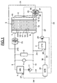
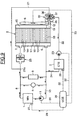
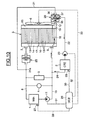
- the cooling circuit illustrated schematically in FIG. 1 is intended for cooling a hybrid traction or propulsion system of a motor vehicle which comprises, on the one hand, a heat engine M TH referenced 1 and, on the other hand, a CTE electric traction or propulsion chain referenced 2 which may comprise one or more electric motors associated with electronic power components.
- FIG. 1 also shows a radiator 3 for heating the passenger compartment of the vehicle and a degassing jar 4 for the heat transfer fluid flowing in the cooling circuit, connected in parallel with the heat engine 1.
- a single radiator 5 capable of being subjected to a flow of air set in motion by a fan 6 comprises an inlet 7 connected by the pipe 8 to the outlet of the heat engine 1.
- the radiator 5 comprises a main outlet 9 connected by the pipe 10 at the inlet of the heat engine 1 with the interposition of a first circulation pump 11.
- the radiator 5 also has an auxiliary output 12.
- the radiator 5 has a main circuit with several passes of multiple parallel channels 13 dedicated to the cooling of the heat engine 1.
- the radiator 5 comprises an inlet box 14 provided with the inlet 7, a deflection box 15 and an output box 16 communicating with the main output 9.
- the input 14 and output 16 boxes are separated by a sealed wall 17.
- the heat transfer fluid entering through the inlet 7 passes first in a different direction parallel channels 13 before returning through the deflection box 15 to cross again channels 13 in the other direction before end in the exit box 16 to exit through the main exit 9.
- the radiator 5 also has an auxiliary circuit communicating with the main circuit through the output box 16.
- the auxiliary circuit is defined by a sealed separation plate 18 which isolates an auxiliary output box 19 communicating with the auxiliary output 12.
- the auxiliary circuit thus set communicates the output box 16 and the main output 9 with the auxiliary output box 19 and the auxiliary output 12.
- the coolant which has flowed in the radiator 5 according to the main circuit can still undergo additional cooling in the auxiliary circuit, which lowers its temperature before the output by the auxiliary output 12.
- a three-way thermostatic mixing valve referenced 20 in FIG. 1 is mounted at the auxiliary outlet 12.
- the valve 20 is, on the other hand, connected to a bypass branch 21 at point 21a. in the pipe 8.
- the mixing valve 20 has an outlet 21 connected by the pipe 22 to a second circulation pump 23 and to the electric traction chain 2.
- the return of the coolant having passed through the electric traction chain 2 is effected by the pipe 24 stitched on the pipe 10.
- a two-way main thermostatic valve 25 is mounted between the tapping 21a and the radiator 5 on the pipe 8.
- the cooling circuit comprises a main loop in which are located the heat engine 1 and the radiator 5 as well as the first circulation pump 11 and the two-way thermostatic valve 25.
- the degassing jar 4 and the radiator 3 for the heating of the passenger compartment of the vehicle are mounted in parallel on the two branches 8 and 10 of this main loop.
- Two branches are provided on the main loop, namely the bypass 21 and the bypass 22, which comprises the electric traction chain and the second circulation pump 23.
- the mixing valve 20 ensures the connection, depending on its position, between the respective branches 21 and 22 and the main loop through the auxiliary circuit defined in the radiator 5.
- the operation of the system as a whole is provided by an electronic control unit UCE referenced 26 in FIG. 1.
- This control unit receives information from a temperature sensor 27 which measures the temperature of the cooling water by output of the heat engine 1, the sensor 27 being connected to the control unit 26 via the connection 28.
- the temperature of the heat transfer fluid at the input of the electric traction chain 2 is also measured by a sensor 29 connected to the control unit.
- control 26 by a connection 30.
- the first pump 11 can be controlled, if it is electrical, by the control unit 26 via a connection 31.
- the second pump 23 is controlled by the control unit by through a connection 32.
- the fan 6 is controlled by the control unit 26 via a connection 33.
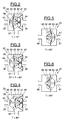
- FIGS. 2 to 4 schematically show an exemplary embodiment of such a three-way thermostatic mixing valve.
- Figures 2 to 4 show a longitudinal section of such a thermostatic valve double valve wax.
- the valve 20 comprises a rigid and sealed housing 34 having two inputs 35, 36 opposite to each other and an outlet 37 in a direction perpendicular to said inlets 35, 36.
- One of the inlets 36 receives the heat transfer fluid from the engine
- the opposite inlet 35 receives the heat transfer fluid cooled by the auxiliary cooling circuit of the radiator 5 and from the auxiliary outlet box 19.
- a wax thermostat 38 having two valves 39 and 40 each disposed at one end of a wax bulb 41 which can move along a rod 42 integral with the housing 34 under the effect of the temperature of the fluid bathing the bulb 41.
- Springs 43 and 44 hold the valves 39 and 40 integral with the wax bulb 41 against the fixed seat 45 and return the valve 39 to seat 45 when the wax contracts.
- a first temperature which may be, for example, 70 ° C.
- the valve 39 is pushed against its seat 45 by the spring 43 so that the passage from the inlet 35 from the auxiliary output 12 of the radiator 5 is blocked. In this position, which is illustrated in FIG. 2, the passage coming from the inlet 36 coming from the heat engine is on the contrary released, the coolant being able to pass through the mixing valve 20 from the inlet 36 to the outlet 37.
- the valve 20 When the temperature of the coolant passing through the valve 20 is between the first temperature, for example 70 ° C, and a second temperature, for example 80 ° C, the valve 20 is placed in the position illustrated in FIG. 3. In this position, the wax has expanded in the bulb 41 which has slid along the rod 42. The valves 39 and 40 which are arranged perpendicular to said rod 42 have moved along this stem. In this position, the heat transfer fluid coming from the inlet 35 can mix in the valve 20 with the coolant coming from the inlet 36, the mixture leaving through the outlet 37.
- the first temperature for example 70 ° C
- a second temperature for example 80 ° C
- the two valves 39 and 40 continue to move so that the valve 40 finally closes the inlet 36 in the position shown in Figure 4 which corresponds to a temperature of the heat transfer fluid greater than the second temperature, for example 80 ° C. In this position, only the coolant coming from the inlet 35 can enter the valve 20 to exit through the outlet 37.
- the mixing valve 20 can be made differently, for example by means of two wax thermostats housed in a single housing or any other structure which effectively makes it possible to alternately close the inlets 35 and 36 and to maintain a intermediate position for which the fluids from the inlets 35 and 36 are mixed in the valve 20.
- the valve 25 has a rigid frame 46 provided with an inlet 47 and an opposite outlet 48.
- the inlet 47 can receive the fluid coolant from the engine.
- the outlet 48 is connected to the main inlet 7 of the radiator 5.
- a single-valve wax thermostat 49 attached to the end of a wax bulb 50 which can move along a rod 51 secured to the housing 46.
- a spring 52 allows the valve 49 to be held against its fixed seat 53.
- the valve 25 is closed when the temperature of the coolant is lower than a third temperature, for example 83 ° C. In this position, illustrated in FIG. 5, the valve 25 blocks any passage between its inlet 47 and its outlet 48, the valve 49 being pressed on its seat 53.
- a third temperature for example 83 ° C.
- the thermostatic valve 25 When the temperature of the heat transfer fluid exceeds a fourth temperature, for example 95 ° C, the thermostatic valve 25 is completely open, as shown in Figure 6, the valve 49 being away from its seat 53 and letting the heat transfer fluid from the entrance 47 to exit 48.
- a fourth temperature for example 95 ° C
- FIG. 7 illustrates the operation of the hybrid vehicle in pure cold thermal mode, that is to say during a cold start using only the engine, the electric power train remaining inactive.
- the circulation of the coolant is illustrated by the arrows 54.
- the second circulation pump 23 is stopped.
- the first circulation pump 11 is in operation, its speed being linked to that of the engine.
- the heat transfer fluid circulated by the pump 11 passes through the heat engine 1, the degassing jar 4, and the heating radiator 3 for the passenger compartment of the vehicle and returns to the circulating pump 11.
- the heat transfer fluid can not cross the thermostatic valve 25 which is closed as long as the temperature of the coolant remains below 83 ° C.
- the heat transfer fluid does not cross the radiator 5 and the fan 6 remains inactive.
- the coolant can also flow through the bypass branch 21, pass through the mixing valve 20, join the bypass branch 22 and pass through the electric drive train before returning to the main cooling circuit via line 10.
- FIG. 8 illustrates the same operation in pure thermal mode hot.
- the heat engine is therefore still active and the electric traction system is inactive.
- the first circulation pump 11 is active while the second circulation pump 23 is inactive.
- the temperature of the heat transfer fluid here exceeded 83 ° C., which caused the opening of the main thermostatic valve 25.
- the heat transfer fluid therefore passes through the radiator 5.
- the fan 6 can be started by the control unit 26 Given the high temperature of the coolant, greater than 80 ° C, the mixing valve 20 has blocked its second inlet 36, preventing the arrival of heat transfer fluid at high temperature from the branch branch 21. In this way, it is avoided that the heat transfer fluid at high temperature can damage the components of the electric power train 2.
- the heat transfer fluid which undergoes a second cooling in the auxiliary circuit of the radiator 5 can pass through the mixing valve 20 and out through its output 37 so as to flow through the bypass 22 through the electric power train 2 to return through the pipe 24 and the pipe 10 on the main cooling circuit of the heat engine 1. It can be seen that the cooling of the heat engine 1 is ensured at the optimum temperature defined by the thermostatic valve 25 and the main circuit of the radiator 5. The heat transfer fluid which nevertheless passes through the electric traction chain is at a lower temperature, compatible with the components of the electric power train.
- Figure 9 illustrates operation of the system in pure electric cold mode.
- the heat engine is inactive and the traction of the vehicle is ensured only by the electric power train 2.
- the circulation pump 23 is started, the first circulation pump It may be inactive or, depending on the case, also be started.
- the main thermostatic valve 25 is in the closed position, the temperature of the coolant being less than 83 ° C, its opening temperature.
- the mixing valve 20 is in a position where it blocks the first inlet 35 and opens only the second inlet 36 connected to the bypass 21. The heat transfer fluid therefore crosses the electric power train 2 being circulated by the pump 23.
- the heat transfer fluid also passes through the heat engine 1, which allows a preheating thereof, then returns through the bypass 21 and the mixing valve 20 on the electric traction chain 2. It will be noted that the heat transfer fluid also passes through the degassing jar 4 and the radiator 3 for the passenger compartment of the vehicle but in a direction opposite to that of FIGS. 7 and 8. By preheating the heat engine 1 , it will consume less and will emit less pollutant gases after startup.
- Figure 10 illustrates the flow of heat transfer fluid in the case of pure electrical operation hot.
- the temperature of the coolant is greater than 80 ° C but remains below 83 ° C due to cooling in the auxiliary circuit of the radiator 5 whose fan 6 was turned on.
- the circulation pump 23 being actuated, the heat transfer fluid passes through the electric drive train 2 and then returns via the pipe 24 and a portion of the pipe 10 to the radiator 5.
- the heat transfer fluid enters through the main outlet 9 of the radiator 5 and therefore flows backwards from previous cases.
- the heat transfer fluid passes through the auxiliary circuit of the radiator 5 and leaves through the auxiliary outlet 12 after having been suitably cooled.
- the mixing valve 20 is in the position where it blocks the second inlet 36 and leaves instead open the first inlet 35.
- the main thermostatic valve 25 is closed.
- Figure 11 illustrates the flow of heat transfer fluid in the case of cold hybrid operation.
- the traction of the vehicle is ensured by both the heat engine 1 and the electric power train 2.
- the two circulation pumps 11 and 23 are actuated. If the speed of the heat engine, and therefore of the pump 11, is sufficient to provide the desired flow rate in the electric power train 2, the pump 23 may not be put into operation.
- the temperature of the coolant is less than 70 ° C. Under these conditions, the mixing valve 20 is in the position where it closes the first inlet 35 and releases the second inlet 36. The heat transfer fluid therefore passes through the electric power train 2 by the bypass 22 and returns through the pipe 10 and passes through the heat engine 1.
- the main thermostatic valve 25 being closed, the heat transfer fluid passes by the bypass 21 to return to the electric power train 2 through the mixing valve 20. Note that the degassing jar 4 and the radiator 3 are also traversed by the coolant, this time in the same direction as on the Figures 7 and 8.
- FIG. 12 illustrates the path of the heat transfer fluid in the case of a hybrid hot operation in the case where the temperature of the coolant is between 80 ° C. and 83 ° C.
- the two circulating pumps 11 and 23 are in operation (unless the speed of the pump 11 is sufficient, as indicated above, in which case the pump 23 may not be commissioning).
- the mixing valve 20 is in the position where it blocks the second inlet 36 since the temperature of the heat transfer fluid passing through it is greater than 80 ° C.
- the main thermostatic valve 25 is in the closed position.
- the heat transfer fluid passes through the auxiliary circuit of the radiator 5 (the fan 6 can be turned on), so as to be cooled to avoid any deterioration of the components of the electric power train. This is cooled by the heat transfer fluid from the auxiliary circuit of the radiator 5, the heat transfer fluid joining the branch branch 22 through the mixing valve 20.
- Figure 13 shows the circulation of the coolant in the case of hybrid operation at higher temperature.
- the temperature of the heat transfer fluid this time exceeded 83 ° C and reached 95 ° C for example, the temperature at which the main thermostatic valve 25 is completely open .
- the two circulating pumps 11 and 23 are in operation (unless the speed of the pump 11 is sufficient, as indicated above, in which case the pump 23 may not be put into operation).
- the heat transfer fluid flows in the main cooling loop through lines 8 and 10 through the main thermostatic valve 25.
- the heat transfer fluid passes through the main circuit of the radiator 5 by entering through the inlet 7 and out through the main outlet 9.
- the cooling of the heat engine 1 is ensured properly by the opening of the thermostatic valve 25 and the cooling carried out by the main circuit of the radiator 5.
- the coolant is however subjected to a greater cooling by also passing through the auxiliary circuit of the radiator 5.
- the heat transfer fluid which has undergone such additional cooling flows through the auxiliary outlet 12 of the radiator 5 and is mixed in the mixing valve 20 with the heat transfer fluid from the bypass 21.
- the mixture of these two fluids at different temperatures keeps the mixing thermostatic valve 20 in its intermediate position as illustrated in Figure 3 or in the position shown in Figure 4.
- the heat transfer fluid from the mixing valve 20 is therefore at a temperature between 70 and 80 ° C. This temperature is adapted to the cooling of the electric traction chain 2.
- the arrangement of the main thermostatic valve at the output of the heat engine makes it possible to use a thermostat of conventional type thus simplifying the design and construction of a hybrid power train cooling system for a motor vehicle.
Landscapes
- Engineering & Computer Science (AREA)
- Chemical & Material Sciences (AREA)
- Combustion & Propulsion (AREA)
- Mechanical Engineering (AREA)
- General Engineering & Computer Science (AREA)
- Hybrid Electric Vehicles (AREA)
- Cooling, Air Intake And Gas Exhaust, And Fuel Tank Arrangements In Propulsion Units (AREA)
- Electric Propulsion And Braking For Vehicles (AREA)
Applications Claiming Priority (1)
| Application Number | Priority Date | Filing Date | Title |
|---|---|---|---|
| FR0412895A FR2879044B1 (fr) | 2004-12-03 | 2004-12-03 | Systeme de refroidissement pour chaine de traction hybride de vehicule automobile |
Publications (2)
| Publication Number | Publication Date |
|---|---|
| EP1669570A2 true EP1669570A2 (de) | 2006-06-14 |
| EP1669570A3 EP1669570A3 (de) | 2011-01-05 |
Family
ID=34953569
Family Applications (1)
| Application Number | Title | Priority Date | Filing Date |
|---|---|---|---|
| EP05300997A Withdrawn EP1669570A3 (de) | 2004-12-03 | 2005-12-02 | Kühlungsanlage für eine hybride Antriebkette eines Kraftfahrzeugs |
Country Status (2)
| Country | Link |
|---|---|
| EP (1) | EP1669570A3 (de) |
| FR (1) | FR2879044B1 (de) |
Cited By (3)
| Publication number | Priority date | Publication date | Assignee | Title |
|---|---|---|---|---|
| ITBO20090181A1 (it) * | 2009-03-25 | 2010-09-26 | Ferrari Spa | Sistema di raffreddamento per un veicolo con propulsione ibrida |
| EP3760848A1 (de) * | 2019-07-05 | 2021-01-06 | Ford Global Technologies, LLC | Anordnung und verfahren zur temperierung eines verbrennungsmotors und elektrischer antriebskomponenten eines hybridfahrzeugs |
| DE102007052263B4 (de) | 2007-11-02 | 2021-11-04 | Bayerische Motoren Werke Aktiengesellschaft | Thermostatventilanordnung |
Families Citing this family (1)
| Publication number | Priority date | Publication date | Assignee | Title |
|---|---|---|---|---|
| FR3070432B1 (fr) * | 2017-08-30 | 2019-08-16 | Psa Automobiles Sa | Ensemble d’un circuit de refroidissement pour un moteur thermique et une boite de vitesses |
Citations (7)
| Publication number | Priority date | Publication date | Assignee | Title |
|---|---|---|---|---|
| US5531285A (en) | 1991-08-01 | 1996-07-02 | Wavedriver Limited | Vehicle cooling system |
| JPH10266855A (ja) | 1997-03-21 | 1998-10-06 | Toyota Motor Corp | ハイブリッド車用動力冷却装置 |
| DE19730678A1 (de) | 1997-07-17 | 1999-01-21 | Volkswagen Ag | Hybridfahrzeug mit einer Vorrichtung zur Kühlung von Antriebsbauteilen und zur Innenraumheizung |
| US6196168B1 (en) | 1996-09-17 | 2001-03-06 | Modine Manufacturing Company | Device and method for cooling and preheating |
| FR2815401A1 (fr) | 2000-10-13 | 2002-04-19 | Renault | Dispositif, systeme et procede de refroidissement d'un fluide caloporteur |
| FR2815402A1 (fr) | 2000-10-13 | 2002-04-19 | Renault | Dispositif, systeme et procede de refroidissement d'un fluide caloporteur |
| FR2844224A1 (fr) | 2002-09-06 | 2004-03-12 | Renault Sa | Systeme de refroidissement d'une chaine de traction hybride pour vehicule automobile. |
Family Cites Families (1)
| Publication number | Priority date | Publication date | Assignee | Title |
|---|---|---|---|---|
| US2435041A (en) * | 1945-02-10 | 1948-01-27 | Frederic W Hild | Regulating device for cooling systems |
-
2004
- 2004-12-03 FR FR0412895A patent/FR2879044B1/fr not_active Expired - Fee Related
-
2005
- 2005-12-02 EP EP05300997A patent/EP1669570A3/de not_active Withdrawn
Patent Citations (7)
| Publication number | Priority date | Publication date | Assignee | Title |
|---|---|---|---|---|
| US5531285A (en) | 1991-08-01 | 1996-07-02 | Wavedriver Limited | Vehicle cooling system |
| US6196168B1 (en) | 1996-09-17 | 2001-03-06 | Modine Manufacturing Company | Device and method for cooling and preheating |
| JPH10266855A (ja) | 1997-03-21 | 1998-10-06 | Toyota Motor Corp | ハイブリッド車用動力冷却装置 |
| DE19730678A1 (de) | 1997-07-17 | 1999-01-21 | Volkswagen Ag | Hybridfahrzeug mit einer Vorrichtung zur Kühlung von Antriebsbauteilen und zur Innenraumheizung |
| FR2815401A1 (fr) | 2000-10-13 | 2002-04-19 | Renault | Dispositif, systeme et procede de refroidissement d'un fluide caloporteur |
| FR2815402A1 (fr) | 2000-10-13 | 2002-04-19 | Renault | Dispositif, systeme et procede de refroidissement d'un fluide caloporteur |
| FR2844224A1 (fr) | 2002-09-06 | 2004-03-12 | Renault Sa | Systeme de refroidissement d'une chaine de traction hybride pour vehicule automobile. |
Cited By (5)
| Publication number | Priority date | Publication date | Assignee | Title |
|---|---|---|---|---|
| DE102007052263B4 (de) | 2007-11-02 | 2021-11-04 | Bayerische Motoren Werke Aktiengesellschaft | Thermostatventilanordnung |
| ITBO20090181A1 (it) * | 2009-03-25 | 2010-09-26 | Ferrari Spa | Sistema di raffreddamento per un veicolo con propulsione ibrida |
| EP2233340A3 (de) * | 2009-03-25 | 2012-02-29 | FERRARI S.p.A. | Kühlsystem für ein Fahrzeug mit Hybridantrieb |
| US8281884B2 (en) | 2009-03-25 | 2012-10-09 | Ferrari S.P.A. | Cooling system for a vehicle with hybrid propulsion |
| EP3760848A1 (de) * | 2019-07-05 | 2021-01-06 | Ford Global Technologies, LLC | Anordnung und verfahren zur temperierung eines verbrennungsmotors und elektrischer antriebskomponenten eines hybridfahrzeugs |
Also Published As
| Publication number | Publication date |
|---|---|
| EP1669570A3 (de) | 2011-01-05 |
| FR2879044A1 (fr) | 2006-06-09 |
| FR2879044B1 (fr) | 2007-03-02 |
Similar Documents
| Publication | Publication Date | Title |
|---|---|---|
| FR2809451A1 (fr) | Moteur thermique a circuit de refroidissement et echangeur de chaleur de chauffage, relie a celui-ci | |
| EP0501854A1 (de) | Krafwagenkühler mit Fluidumzirkulationssteuereinrichtung | |
| EP1132229B1 (de) | Kraftfahrzeugklimaanlage mit einem Mehrzweckwärmetauscher | |
| EP2112347B1 (de) | Kühlmittelkreislauf eines Motors | |
| EP0960755A1 (de) | Klimakreislauf unter Verwendung einer Kühlflüssigkeit im superkritischen Zustand, insbesondere für Fahrzeuge | |
| FR2748428A1 (fr) | Systeme de refroidissement pour vehicule a propulsion hybride | |
| EP2069620A2 (de) | Vorrichtung zur verteilung einer kühlflüssigkeit in einem kraftfahrzeugmotor | |
| EP0595713B1 (de) | Verfahren und Anlage zur Klimatisierung eines Fahrzeugs, insbesondere eines Elektrofahrzeugs | |
| FR2844224A1 (fr) | Systeme de refroidissement d'une chaine de traction hybride pour vehicule automobile. | |
| EP0292373A1 (de) | Heizungssystem für ein Kraftfahrzeug mit einem Wärmegenerator | |
| EP1669570A2 (de) | Kühlungsanlage für eine hybride Antriebkette eines Kraftfahrzeugs | |
| FR2744071A1 (fr) | Dispositif de chauffage pour vehicule utilisant le circuit de fluide refrigerant | |
| EP1362168B1 (de) | Vorrichtung, system und verfahren zum kühlen eines kühlmittels | |
| EP1658419A1 (de) | Vorrichtung zur wärmeregelung von abgas | |
| EP2748022B1 (de) | Vorrichtung zur steuerung des flusses eines kühlmittels und schaltkreis mit dieser vorrichtung | |
| FR2890697A1 (fr) | Moteur de vehicule comprenant un circuit de gaz recircules refroidis a basse temperature | |
| WO2008029029A1 (fr) | Dispositif de distribution de liquide de refroidissement dans un moteur de vehicule automobile | |
| FR2909595A3 (fr) | Systeme de regulation thermique et son utilisation pour un vehicule automobile. | |
| FR2914694A1 (fr) | Systeme de gestion des echanges thermiques d'un moteur de vehicule automobile | |
| FR2976322A1 (fr) | Repartiteur d'air comprenant un dispositif adapte a echanger de la chaleur avec de l'air de suralimentation, et systeme de transfert thermique comprenant un tel repartiteur | |
| EP1556659B1 (de) | Wärmetauscher mit durchflussregelung, insbesondere für kraftfahrzeuge | |
| FR2932845A1 (fr) | Procede et dispositif de refroidissement d'un moteur thermique. | |
| EP1828560A1 (de) | Wärmeenergieverwaltungssystem für einen fahrzeugmotor, das mit einem zeitverzögerungsschaltmittel versehen ist | |
| EP3557177B1 (de) | Kühlradiator mit integriertem by-pass und kühlkreislauf | |
| FR2815402A1 (fr) | Dispositif, systeme et procede de refroidissement d'un fluide caloporteur |
Legal Events
| Date | Code | Title | Description |
|---|---|---|---|
| PUAI | Public reference made under article 153(3) epc to a published international application that has entered the european phase |
Free format text: ORIGINAL CODE: 0009012 |
|
| AK | Designated contracting states |
Kind code of ref document: A2 Designated state(s): AT BE BG CH CY CZ DE DK EE ES FI FR GB GR HU IE IS IT LI LT LU LV MC NL PL PT RO SE SI SK TR |
|
| AX | Request for extension of the european patent |
Extension state: AL BA HR MK YU |
|
| RIN1 | Information on inventor provided before grant (corrected) |
Inventor name: ROUAUD, CEDRIC Inventor name: YU, ROBERT |
|
| PUAL | Search report despatched |
Free format text: ORIGINAL CODE: 0009013 |
|
| AK | Designated contracting states |
Kind code of ref document: A3 Designated state(s): AT BE BG CH CY CZ DE DK EE ES FI FR GB GR HU IE IS IT LI LT LU LV MC NL PL PT RO SE SI SK TR |
|
| AX | Request for extension of the european patent |
Extension state: AL BA HR MK YU |
|
| 17P | Request for examination filed |
Effective date: 20110704 |
|
| AKX | Designation fees paid |
Designated state(s): AT BE BG CH CY LI |
|
| RBV | Designated contracting states (corrected) |
Designated state(s): AT BE BG CH CY CZ LI |
|
| RBV | Designated contracting states (corrected) |
Designated state(s): AT BE BG CH CY CZ DE DK EE ES FI FR GB GR HU IE IS IT LI LT LU LV MC NL PL PT RO SE SI SK TR |
|
| REG | Reference to a national code |
Ref country code: DE Ref legal event code: R108 Effective date: 20110907 |
|
| STAA | Information on the status of an ep patent application or granted ep patent |
Free format text: STATUS: THE APPLICATION IS DEEMED TO BE WITHDRAWN |
|
| 18D | Application deemed to be withdrawn |
Effective date: 20110706 |