EP1669560A1 - Apparatus and method for controlling a variable valve mechanism - Google Patents
Apparatus and method for controlling a variable valve mechanism Download PDFInfo
- Publication number
- EP1669560A1 EP1669560A1 EP05257456A EP05257456A EP1669560A1 EP 1669560 A1 EP1669560 A1 EP 1669560A1 EP 05257456 A EP05257456 A EP 05257456A EP 05257456 A EP05257456 A EP 05257456A EP 1669560 A1 EP1669560 A1 EP 1669560A1
- Authority
- EP
- European Patent Office
- Prior art keywords
- command value
- value
- variable valve
- characteristic
- operation angle
- Prior art date
- Legal status (The legal status is an assumption and is not a legal conclusion. Google has not performed a legal analysis and makes no representation as to the accuracy of the status listed.)
- Granted
Links
- 230000007246 mechanism Effects 0.000 title claims abstract description 114
- 238000000034 method Methods 0.000 title claims description 20
- 238000001514 detection method Methods 0.000 claims description 67
- 238000002485 combustion reaction Methods 0.000 claims description 17
- 230000008859 change Effects 0.000 abstract description 8
- 238000010586 diagram Methods 0.000 description 13
- 230000002159 abnormal effect Effects 0.000 description 7
- 230000008569 process Effects 0.000 description 7
- 230000001276 controlling effect Effects 0.000 description 4
- 230000001105 regulatory effect Effects 0.000 description 4
- 230000006866 deterioration Effects 0.000 description 3
- 230000000694 effects Effects 0.000 description 3
- 238000004891 communication Methods 0.000 description 2
- 230000007423 decrease Effects 0.000 description 2
- 230000006872 improvement Effects 0.000 description 2
- 239000011435 rock Substances 0.000 description 2
- 230000006978 adaptation Effects 0.000 description 1
- 230000004075 alteration Effects 0.000 description 1
- 230000005540 biological transmission Effects 0.000 description 1
- 239000000498 cooling water Substances 0.000 description 1
- 238000005516 engineering process Methods 0.000 description 1
- 230000002349 favourable effect Effects 0.000 description 1
- 230000006870 function Effects 0.000 description 1
- 239000010687 lubricating oil Substances 0.000 description 1
- 230000004048 modification Effects 0.000 description 1
- 238000012986 modification Methods 0.000 description 1
- 239000003921 oil Substances 0.000 description 1
Images







Classifications
-
- F—MECHANICAL ENGINEERING; LIGHTING; HEATING; WEAPONS; BLASTING
- F02—COMBUSTION ENGINES; HOT-GAS OR COMBUSTION-PRODUCT ENGINE PLANTS
- F02D—CONTROLLING COMBUSTION ENGINES
- F02D13/00—Controlling the engine output power by varying inlet or exhaust valve operating characteristics, e.g. timing
- F02D13/02—Controlling the engine output power by varying inlet or exhaust valve operating characteristics, e.g. timing during engine operation
- F02D13/0203—Variable control of intake and exhaust valves
- F02D13/0207—Variable control of intake and exhaust valves changing valve lift or valve lift and timing
-
- F—MECHANICAL ENGINEERING; LIGHTING; HEATING; WEAPONS; BLASTING
- F02—COMBUSTION ENGINES; HOT-GAS OR COMBUSTION-PRODUCT ENGINE PLANTS
- F02D—CONTROLLING COMBUSTION ENGINES
- F02D13/00—Controlling the engine output power by varying inlet or exhaust valve operating characteristics, e.g. timing
- F02D13/02—Controlling the engine output power by varying inlet or exhaust valve operating characteristics, e.g. timing during engine operation
-
- F—MECHANICAL ENGINEERING; LIGHTING; HEATING; WEAPONS; BLASTING
- F01—MACHINES OR ENGINES IN GENERAL; ENGINE PLANTS IN GENERAL; STEAM ENGINES
- F01L—CYCLICALLY OPERATING VALVES FOR MACHINES OR ENGINES
- F01L1/00—Valve-gear or valve arrangements, e.g. lift-valve gear
- F01L1/34—Valve-gear or valve arrangements, e.g. lift-valve gear characterised by the provision of means for changing the timing of the valves without changing the duration of opening and without affecting the magnitude of the valve lift
-
- F—MECHANICAL ENGINEERING; LIGHTING; HEATING; WEAPONS; BLASTING
- F01—MACHINES OR ENGINES IN GENERAL; ENGINE PLANTS IN GENERAL; STEAM ENGINES
- F01L—CYCLICALLY OPERATING VALVES FOR MACHINES OR ENGINES
- F01L13/00—Modifications of valve-gear to facilitate reversing, braking, starting, changing compression ratio, or other specific operations
-
- F—MECHANICAL ENGINEERING; LIGHTING; HEATING; WEAPONS; BLASTING
- F01—MACHINES OR ENGINES IN GENERAL; ENGINE PLANTS IN GENERAL; STEAM ENGINES
- F01L—CYCLICALLY OPERATING VALVES FOR MACHINES OR ENGINES
- F01L13/00—Modifications of valve-gear to facilitate reversing, braking, starting, changing compression ratio, or other specific operations
- F01L13/0015—Modifications of valve-gear to facilitate reversing, braking, starting, changing compression ratio, or other specific operations for optimising engine performances by modifying valve lift according to various working parameters, e.g. rotational speed, load, torque
- F01L13/0021—Modifications of valve-gear to facilitate reversing, braking, starting, changing compression ratio, or other specific operations for optimising engine performances by modifying valve lift according to various working parameters, e.g. rotational speed, load, torque by modification of rocker arm ratio
-
- F—MECHANICAL ENGINEERING; LIGHTING; HEATING; WEAPONS; BLASTING
- F01—MACHINES OR ENGINES IN GENERAL; ENGINE PLANTS IN GENERAL; STEAM ENGINES
- F01L—CYCLICALLY OPERATING VALVES FOR MACHINES OR ENGINES
- F01L13/00—Modifications of valve-gear to facilitate reversing, braking, starting, changing compression ratio, or other specific operations
- F01L13/0015—Modifications of valve-gear to facilitate reversing, braking, starting, changing compression ratio, or other specific operations for optimising engine performances by modifying valve lift according to various working parameters, e.g. rotational speed, load, torque
- F01L13/0021—Modifications of valve-gear to facilitate reversing, braking, starting, changing compression ratio, or other specific operations for optimising engine performances by modifying valve lift according to various working parameters, e.g. rotational speed, load, torque by modification of rocker arm ratio
- F01L13/0026—Modifications of valve-gear to facilitate reversing, braking, starting, changing compression ratio, or other specific operations for optimising engine performances by modifying valve lift according to various working parameters, e.g. rotational speed, load, torque by modification of rocker arm ratio by means of an eccentric
-
- F—MECHANICAL ENGINEERING; LIGHTING; HEATING; WEAPONS; BLASTING
- F02—COMBUSTION ENGINES; HOT-GAS OR COMBUSTION-PRODUCT ENGINE PLANTS
- F02D—CONTROLLING COMBUSTION ENGINES
- F02D41/00—Electrical control of supply of combustible mixture or its constituents
- F02D41/22—Safety or indicating devices for abnormal conditions
- F02D41/222—Safety or indicating devices for abnormal conditions relating to the failure of sensors or parameter detection devices
-
- F—MECHANICAL ENGINEERING; LIGHTING; HEATING; WEAPONS; BLASTING
- F01—MACHINES OR ENGINES IN GENERAL; ENGINE PLANTS IN GENERAL; STEAM ENGINES
- F01L—CYCLICALLY OPERATING VALVES FOR MACHINES OR ENGINES
- F01L13/00—Modifications of valve-gear to facilitate reversing, braking, starting, changing compression ratio, or other specific operations
- F01L13/0015—Modifications of valve-gear to facilitate reversing, braking, starting, changing compression ratio, or other specific operations for optimising engine performances by modifying valve lift according to various working parameters, e.g. rotational speed, load, torque
- F01L13/0063—Modifications of valve-gear to facilitate reversing, braking, starting, changing compression ratio, or other specific operations for optimising engine performances by modifying valve lift according to various working parameters, e.g. rotational speed, load, torque by modification of cam contact point by displacing an intermediate lever or wedge-shaped intermediate element, e.g. Tourtelot
- F01L2013/0073—Modifications of valve-gear to facilitate reversing, braking, starting, changing compression ratio, or other specific operations for optimising engine performances by modifying valve lift according to various working parameters, e.g. rotational speed, load, torque by modification of cam contact point by displacing an intermediate lever or wedge-shaped intermediate element, e.g. Tourtelot with an oscillating cam acting on the valve of the "Delphi" type
-
- F—MECHANICAL ENGINEERING; LIGHTING; HEATING; WEAPONS; BLASTING
- F02—COMBUSTION ENGINES; HOT-GAS OR COMBUSTION-PRODUCT ENGINE PLANTS
- F02D—CONTROLLING COMBUSTION ENGINES
- F02D13/00—Controlling the engine output power by varying inlet or exhaust valve operating characteristics, e.g. timing
- F02D13/02—Controlling the engine output power by varying inlet or exhaust valve operating characteristics, e.g. timing during engine operation
- F02D13/0261—Controlling the valve overlap
- F02D13/0265—Negative valve overlap for temporarily storing residual gas in the cylinder
-
- F—MECHANICAL ENGINEERING; LIGHTING; HEATING; WEAPONS; BLASTING
- F02—COMBUSTION ENGINES; HOT-GAS OR COMBUSTION-PRODUCT ENGINE PLANTS
- F02D—CONTROLLING COMBUSTION ENGINES
- F02D41/00—Electrical control of supply of combustible mixture or its constituents
- F02D41/0002—Controlling intake air
- F02D2041/001—Controlling intake air for engines with variable valve actuation
-
- Y—GENERAL TAGGING OF NEW TECHNOLOGICAL DEVELOPMENTS; GENERAL TAGGING OF CROSS-SECTIONAL TECHNOLOGIES SPANNING OVER SEVERAL SECTIONS OF THE IPC; TECHNICAL SUBJECTS COVERED BY FORMER USPC CROSS-REFERENCE ART COLLECTIONS [XRACs] AND DIGESTS
- Y02—TECHNOLOGIES OR APPLICATIONS FOR MITIGATION OR ADAPTATION AGAINST CLIMATE CHANGE
- Y02T—CLIMATE CHANGE MITIGATION TECHNOLOGIES RELATED TO TRANSPORTATION
- Y02T10/00—Road transport of goods or passengers
- Y02T10/10—Internal combustion engine [ICE] based vehicles
- Y02T10/12—Improving ICE efficiencies
-
- Y—GENERAL TAGGING OF NEW TECHNOLOGICAL DEVELOPMENTS; GENERAL TAGGING OF CROSS-SECTIONAL TECHNOLOGIES SPANNING OVER SEVERAL SECTIONS OF THE IPC; TECHNICAL SUBJECTS COVERED BY FORMER USPC CROSS-REFERENCE ART COLLECTIONS [XRACs] AND DIGESTS
- Y02—TECHNOLOGIES OR APPLICATIONS FOR MITIGATION OR ADAPTATION AGAINST CLIMATE CHANGE
- Y02T—CLIMATE CHANGE MITIGATION TECHNOLOGIES RELATED TO TRANSPORTATION
- Y02T10/00—Road transport of goods or passengers
- Y02T10/10—Internal combustion engine [ICE] based vehicles
- Y02T10/40—Engine management systems
Definitions
- the present invention relates to an apparatus and method for controlling a variable valve mechanism and particularly, but not exclusively, a variable valve mechanism which, within a specified variable range, can continuously change the lift characteristic amounts for an internal combustion engine (“engine”) intake valve or exhaust valve (hereafter “intake/exhaust valve”), such as the valve lift amount/operation angle, the valve timing, etc.
- engine internal combustion engine
- intake/exhaust valve exhaust valve
- the invention also relates to a variable valve mechanism, to an engine and to a vehicle.
- variable valve mechanisms In the field of internal combustion engines for automobiles, a variety of variable valve mechanisms have conventionally been proposed, with changeable lift characteristic amounts such as the intake/exhaust valve lift amount, operation angle, and valve timing. Additional background on variable valve timing is described in Unexamined Japanese Patent Application Publication No. 2002-54466 and in U.S. Patent No. 6,843,226, entitled “Intake control apparatus for internal combustion engine,” issued on January 18, 2005, both of which are commonly assigned.
- Feedback control is preferably performed based on the detected value of lift characteristic amounts to maintain lift characteristic amounts at their target values with good precision.
- feedback control technology is commonly known. Simply explained, target values for the lift characteristic amounts are calculated according to the engine operating conditions (load, number of revolutions, etc.), detection values equivalent to the actual lift characteristic amount values are obtained using an appropriate sensor, and the command value for the variable valve mechanism actuator is calculated based on the deviation of these target values and detection values.
- operation angle minimum value 40 may become extremely small as shown in Figure 21.
- operation angle maximum value 41 may become extremely large, causing an excess of residual gas within the cylinders.
- an apparatus for controlling a variable valve mechanism for an internal combustion engine intake valve or exhaust valve wherein a characteristic lift amount of the variable valve mechanism is continuously variable within a specified range comprising first actuator means for driving the variable valve mechanism and first detection means for detecting the characteristic lift amount set by the first actuator means in the variable valve mechanism, the apparatus being arranged to control the first actuator means to vary the characteristic lift amount within the specified range during a normal operation mode and to vary the characteristic lift amount within a sub-range of the specified range during an error operation mode when an error occurs in the first detection means.
- the first detection means is operable to obtain a detection value indicative of the characteristic lift amount set by the first actuator means
- the apparatus further comprises target value calculation means for calculating a target value for the characteristic lift amount based on current engine operating conditions, first command value setting means for setting a first command value for the characteristic lift amount, based on the current target value and the detection value, second command value setting means for setting a second command value for the characteristic lift amount, error determination means for determining when an error occurs in first detection means, and command value switching means for outputting the first command value to the first actuator means during normal operation of the first detection means and for outputting the second command value to the first actuator means when an error occurs in the first detection means, wherein the second command value output from the second command value setting means is selected from within a sub-range of the specified range.
- the sub-range is a sub-range of intermediate values of the specified range.
- the apparatus is arranged to control the first actuator means to vary the characteristic lift amount within the specified range during a normal operation mode based on a target value for current engine operating conditions and a current characteristic lift amount detected by the first detection means.
- the apparatus is arranged to control the first actuator means to vary the characteristic lift amount within the sub-range of the specified range during an error operation mode based on an engine revolution count.
- the apparatus is arranged to control the first actuator means to vary the characteristic lift amount within the sub-range of the specified range during an error operation mode based on a target value for current engine operating conditions.
- the apparatus is arranged to store a learned relationship value between a selected a target value for current engine operating conditions and a corresponding command value output to the first actuator means during the normal mode of operation, and wherein the apparatus is arranged to control the first actuator means to vary the characteristic lift amount within the specified range during an error operation mode based on the current target value and the learned relationship value.
- the second command value setting means is arranged to calculate the second command value based on an engine revolution count, optionally such that the second command value is higher when the engine revolution count is higher.
- the second command value setting means is arranged to calculate the second command value based on the calculated current target value, optionally such that the second command value is higher when the current target value is higher.
- the apparatus further comprises learning means for calculating and storing a learned relationship value between a selected current target value and a corresponding first command value during normal operation, wherein the second command value setting means is arranged to calculate the second command value based on the current target value and the learned relationship value.
- the apparatus further comprises deviation learning means for calculating and storing the relationship between a current target value and a deviation between at least two current detection values from at least two variable valve mechanisms as a learned deviation value during normal operation, wherein the second command value setting means is arranged to calculate a second command value for a first one of the variable valve mechanisms based on the current target value, the learned deviation value, and a first command value for a second one of the variable valve mechanisms.
- the apparatus further comprises ratio learning means for calculating and storing the relationship between a current target value and a current ratio of detection values from at least two variable valve mechanisms as a learned ratio value during normal operation, wherein the second command value setting means is arranged to calculate a second command value for a first one of the variable valve mechanisms based on the current target value, the learned ratio value, and a first command value for a second one of the variable valve mechanisms.
- variable valve mechanism having an apparatus as described in one or more of the preceding paragraphs and comprising a lift operation angle changing mechanism including:
- a variable valve mechanism in which lift characteristic amounts for an internal combustion engine intake valve or exhaust valve are continuously changeable within a specified variable range, an actuator to drive this variable valve mechanism, a detecting means for obtaining a detection value for said lift characteristic amounts, a target value calculation means which calculates a target value for said lift characteristic amounts based on engine operating conditions, a first command value calculation means for calculating a first command value for said lift characteristic amounts, based on said target value and detection value, a second command value setting means for setting a second command value for said lift characteristic amounts, an error determination means for determining an error for said detecting means, and a command value switching means for outputting the first command value to the actuator during normal operation of said detecting means, and outputting the second command value to the actuator during an error, said second command value setting means setting the second command value from within a range including intermediate values in said variable range.
- variable valve mechanism control device comprising a variable valve mechanism for an internal combustion engine intake valve or exhaust valve, wherein a characteristic lift amount of the variable valve mechanism is continuously variable within a specified range, a first actuator to drive the variable valve mechanism and a first sensor to detect the current characteristic lift amount being set by the first actuator in the variable valve mechanism; wherein the variable valve mechanism control device is adapted to control the first actuator to vary the characteristic lift amount within the specified range during a normal operation mode and to vary the characteristic lift amount within a sub-range of the specified range during an error operation mode when an error occurs in the first sensor.
- a variable valve mechanism control device comprising a variable valve mechanism for an internal combustion engine intake valve or exhaust valve, wherein a characteristic lift amount of the variable valve mechanism is continuously variable within a specified range, an actuator to drive the variable valve mechanism, a detecting means for obtaining a detection value indicative of the current characteristic lift amount being set by the variable valve mechanism, a target value calculation means which calculates a current target value for the characteristic lift amount based on current engine operating conditions, a first command value setting means for setting a first command value output for the characteristic lift amount, based on the current target value and the detection value, a second command value setting means for setting a second command value output for the characteristic lift amount, an error determination means for determining when an error occurs in the detecting means and a command value switching means to couple the first command value output to the actuator during normal operation of the detecting means and to couple the second command value output to the actuator when an error occurs in the detecting means, wherein the second command value output from the second command value setting means is
- an internal combustion engine including a variable valve mechanism for an intake valve or exhaust valve, wherein a characteristic lift amount of the variable valve mechanism is continuously variable within a specified range, and comprising an apparatus, mechanism or device as described in one or more of the preceding paragraphs.
- a vehicle having an apparatus, a variable valve mechanism or an engine as described in one or more of the preceding paragraphs.
- Embodiments of the invention provide a variable valve mechanism which can continuously change internal combustion engine intake valve or exhaust valve lift characteristic amounts within a specified variable range, an actuator which drives said variable valve mechanism, and a detection means for obtaining detection values for said lift characteristic amounts.
- the lift characteristic amount target values are calculated based on the engine operating conditions, errors of said detection means are determined, and when said detection means is normal, a first command value for said lift characteristic amounts is calculated based on said target value and said detection value, and this first command value is output to the actuator.
- a lift characteristic amount second command value is set within a range including middle values in said variable range, and this second command value is output to the actuator.
- the second command value selected from a range including middle values in the variable range is output to the actuator, enabling operation using mid-range values for the lift characteristic amounts.
- the invention provides improving engine operability when an error occurs, compared to the conventional example in which lift characteristic amounts are maintained during an error at a maximum value or minimum value corresponding to a mechanical connector position.
- a variable valve mechanism control method being a variable valve control method having a variable valve mechanism with which lift characteristic amounts for an internal combustion engine intake valve or exhaust valve are continuously changeable within a specified variable range, an actuator to drive this variable valve mechanism, and a detecting means for obtaining a detection value for said lift characteristic amounts, the method having a step which calculates a target value for said lift characteristic amounts based on engine operating conditions, a step for determining an error of said detecting means, a step for calculating a first command value for said lift characteristic amounts based on said target value and the detection value and outputting this first command value to the actuator during normal operation of said detecting mean and a step for setting a second command value for said lift characteristic amounts from within a range including intermediate values in said variable range and outputting this second command value to the actuator when an error occurs in said detecting means.
- the sub-range of valve lift characteristic values is a sub-range of intermediate valve lift characteristic values of the specified variable range.
- outputting a second command value to the actuator further comprises outputting a second command value to the actuator, where the second command value is selected from within the sub-range of valve lift characteristic values based on an engine revolution count.
- outputting a second command value to the actuator further comprises outputting a second command value to the actuator, where the second command value is selected from within the sub-range of valve lift characteristic values based on the target value for current engine operating conditions.
- the method of further comprises storing a learned relationship value between a selected a target value for current engine operating conditions and a corresponding command value output to the actuator during the normal operation and outputting a second command value to the actuator, wherein the second command value is selected from within the specified variable range of valve lift characteristic values when an error is identified in the sensor based on the target value and the learned relationship value.
- the method of claim further comprises storing a learned deviation value between the detection value of the sensor and a second detection value of a second sensor of a second variable valve mechanism at a selected target value for current engine operating conditions during normal operation; and outputting a second command value to a second actuator of the second variable valve mechanism when an error is identified in the second sensor, wherein the second command value is selected from within the specified variable range of valve lift characteristic values based on the target value, the learned deviation value, and the first command value for the actuator of the variable valve mechanism.
- the method further comprises storing a learned ratio value between the detection value of the sensor and a second detection value of a second sensor of a second variable valve mechanism at a selected target value for current engine operating conditions during normal operation; and outputting a second command value to a second actuator of the second variable valve mechanism when an error is identified in the second sensor, wherein the second command value is selected from within the specified variable range of valve lift characteristic values based on the target value, the learned ratio value, and the first command value for the actuator of the variable valve mechanism
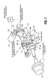
- Figure 1 shows a lift operation angle changing mechanism 10, in which both the operation angle and the valve lift amount (maximum lift amount) of an intake valve 12 can be continuously changed, and a phase changing mechanism 70, which can continuously change the valve timing (open/close timing) of an intake valve 12.
- These mechanisms 10 and 70 are already commonly known as described in Unexamined Japanese Patent Application Publication No. 2002-54466, so only an overview is described here.
- One pair of intake valves 12 are provided for each cylinder, and a valve lifter 19 is provided at the top portion of each intake valve 12. Above these valve lifters 19, a hollow drive shaft 13 with a lubricating oil path formed in its interior is located along the cylinder row direction.
- Rotational motive power is transmitted to the drive shaft 13 from a crankshaft via the phase changing mechanism 70, and it is rotatably driven to link with the crankshaft.
- a rocking cam 20 is externally fitted onto each cylinder such that rocking is possible.
- Each rocking cam 20 has one pair of cam portions 20A, respectively, contacting the top surface of one pair of valve lifters 19 on each cylinder, and by rocking this rocking cam 20, intake valve 12 rises, that is, lifts, via cam portions 20A and valve lifters 19.
- the operation angle changing mechanism 10 is eccentrically provided on the outer perimeter of drive shaft 13, and has an eccentric cam 15 rotating as one unit with drive shaft 13, a control shaft 16 located along the cylinder row direction approximately parallel to the drive shaft 13, a control cam 17 provided eccentrically on the outer perimeter of the control shaft 16 and rotating as one unit therewith, a rocker arm 18 externally fitted on the outer perimeter surface to form the cylinder surface of control cam 17 such that rocking is possible, a ring-shaped link (first link) 25 linking one end of the rocker arm 18 to the eccentric cam 15, and a rod-shaped link (second link) 26 linking the other end of the rocker arm 18 to the rocking cam 20.
- first link first link
- second link rod-shaped link
- One end of the ring-shaped link 25 is externally fitted onto the outer perimeter surface to form the cylinder surface of the eccentric cam 15 such that relative rotation is possible, and the other end is connected to one end of the rocker arm 18 via a first connecting pin 21 such that relative rotation is possible.
- One end of the rod-shaped link 26 is connected via a second pin 28 to the other end of the rocker arm 18 such that relative rotation is possible, and the other end is connected via a third pin 29 to one cam portion 20A such that relative rotation is possible.
- the axial center of the eccentric cam 15 is eccentric to the axial center of the drive shaft 13 by a specified amount
- the axial center of the control cam 17 is eccentric to the axial center of the control shaft 16 by a specified amount.
- Journal portion 20B of the rocking cam 20 and the control shaft 16 are rotatably supported by a cylinder head via a bearing bracket (not shown).
- the control shaft 16 is rotatably driven by a motor 51, which serves as an actuator, and is held in a specified rotation position.
- a worm gear 52 provided on an output shaft 51a of the motor 51, is a simple structure that directly meshes with a worm gear wheel 50 fixed coaxially to one end of the control shaft 16.
- This type of operation angle changing mechanism 10 is easily lubricated and has superior durability and reliability. Furthermore resistance to changing the operation angle is suppressed to a minimum because it has surface contact with the bearing portions for the eccentric cam 15 and the control cam 17 as well as each pin. Also, because the rocking cam 20 for driving the intake valve 12 is placed coaxially with the drive shaft 13, compared to a composition in which the driving cam is supported with a shaft that is different from drive shaft 13, there is superior control precision, the device itself is compact, and vehicle mounting ability is good.
- the rod-shaped link 26 is placed so that it almost aligns with the upper and lower direction of the engine, the amount of extension to the side of the engine (left and right direction in Figure 1) is suppressed.
- the link mechanism is simple and does not use a spring or other energizing means in the transmission route from the drive shaft 13 to the rocking cam 20, resulting in superior reliability and durability.
- phase changing mechanism 70 For the phase changing mechanism 70, a rotation force from the crankshaft is transmitted via a timing belt (not shown) to provide relative rotation of the drive shaft 13 and a cam pulley 71, which is rotatably linked with the crankshaft and the center phase of the operation angle of the intake valve 12, which is the valve timing, is continuously changed in relation to the crankshaft.
- a timing belt not shown
- cam pulley 71 Inside a housing 72 that rotates as one unit with the cam pulley 71 are installed a commonly known vane or spline mechanism and a hydraulic circuit for rotatably driving the drive shaft in the advance-angle or lag-angle directions.
- a control unit 54 has a function to memorize and execute various engine control processes including the control process described below, based on the input of detected signals, such as the engine revolution signal, engine load signal, cooling water temperature signal, and operating oil temperature signal.
- the angle of the control shaft 16 corresponding to the lift characteristic amounts (valve lift amount and operating angle) of the lift operation angle changing mechanism 10 is detected by a potentiometer, such as an operation angle sensor (control shaft sensor) 53.
- the operation angle sensor 53 is supported by a bracket 55, which is fixed to the cylinder head, and detects the rotation angle of the control shaft 16, more specifically of a pin 53a which rotates as one unit with the control shaft 16
- the operation angle sensor 53 outputs the detection value (signal) to the control unit 54.
- a rotation angle regulating pin 56 is fixed to the rear outer perimeter of the control shaft 16. This rotation angle regulating pin 56 moves between a pair of stoppers 57 provided on the bracket 55 in order to secure control shaft 16.
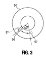
- rotatable angle range ⁇ 1 through which the control shaft 16 can mechanically and physically rotate, is restricted and regulated from the minimum position to the maximum position by the rotation angle regulating pin 56 and the pair of stoppers 57.
- the mechanical variable range of the lift characteristic amount is limited to a range from a minimum value to a maximum value.
- control routines are memorized by said control unit 54 and are repeatedly executed for each specified period (for example, every 10ms).
- the operation angle is used to conveniently describe the lift characteristic amount, however, the valve lift amount could also be used.
- the same reference numbers are essentially applied to the identical processes, so redundant explanations are omitted as appropriate.
- the target operation angle equivalent to the target value for the lift characteristic amount is computed/calculated based on accelerator opening APO that corresponds with the number of engine revolutions and the requested engine load (target value calculating means). Said number of engine revolutions is calculated based on, for example, a detection value from commonly known crank angle sensor 31.
- the APO is detected by accelerator opening sensor 32, for example, which detects the accelerator pedal opening.
- any error of the operation angle sensor 53 as a detection means is detected/determined.
- the actual operation angle corresponds to the operation angle sensor 53 detection value, and is calculated based on this detection value. Even when feedback control cannot be performed for a reason other than an error of the sensor itself, such as because of a communication problem, this S12/B12 determines an error.
- Step S12/B12 is determined as an error.
- the failure (error) control amount which is the second command value for the lift characteristic amount, is calculated with reference to the table showing the number of engine revolutions/operation angle control amount, which is pre-set and pre-stored, based on the number of engine revolutions. As shown in Figure 6, the higher the number of engine revolutions, the greater the air intake amount becomes, so the failure control amount is also set higher.
- either the normal control amount or the failure control amount is output as the operation angle control amount to motor 51, which is actuator 51 for lift operation angle changing mechanism 10 (command value switching means).
- motor 51 operates in accordance with this operation angle control amount to change or maintain the rotation position of control shaft 16, thus controlling the valve lift amount and operation angle of intake valve 12, which are the lift characteristic amounts.
- the normal control value is calculated based on the deviation between the target operation angle and the actual operation angle detected by operating angle sensor 53, which is then output to motor 51 to perform said feedback control.
- the failure control amount output to motor 51 when such a sensor error occurs is calculated based on the number of engine revolutions, as described above, this value changes according to the number of engine revolutions. In other words, it is calculated according to this number of engine revolutions from within a range including intermediate values in the lift characteristic amount variable range.
- variable range for the lift characteristic amount is increased or when the variable range used for feedback control is set at a narrow range in relation to the variable range that is mechanically limited (for example, to a range corresponding to range ⁇ 1 for the control shaft shown in Figure 3), and if open control is performed of the maximum and minimum value of the mechanically variable range of the lift characteristic amount, this control is very useful for a variable valve mechanism that causes operation failures.
- the lift characteristic amount is varied slightly based on only the number of engine revolutions, control is simple and stability is superior. This can be easily applied to existing devices, and because, unlike said conventional example, the lift characteristic value is not switched between the minimum value and the maximum value according to the operation range, a torque jump does not occurs due to this switching.
- the failure control amount is calculated with reference to the pre-set and pre-stored operation angle/operation angle control amount table shown in Figure 9 based on the target operation angle.
- the failure control amount is calculated based on the target operation angle.
- the failure control amount is basically set such that it increases as the target operation angle increases, and decreases as the target operation angle decreases, so that the operation angle is follows the target operation value when a failure occurs.
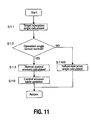
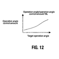
- the learned value for the failure control amount corresponding to the actual operation angle is calculated and stored based on the actual operation angle and the normal control amount calculated at S13/B13. More specifically, the previously set and stored values in the operation angle/operation angle control amount table shown in Figure 12 is updated one after another. And at S14B/B14B, the failure control amount is calculated based on the target operation angle and the learned value. More specifically, the failure control amount is obtained by looking up values from the table in Figure 12, which has been continually updated at S16/B16 based on the target operation angle.
- the third embodiment when feedback control is performed under normal conditions, learned values are calculated based on the actual operation angle and the normal control amount, and the learned value is used to obtain the failure control amount when a failure occurs so the effects of deterioration over time or fluctuations occurring when the failure control amount is calculated can be absorbed or offset, resulting in improved precision when setting the failure control amount when a sensor error occurs.
- lift operation angle changing mechanism 10 has been applied respectively to left and right banks 1 and 2 of a V-type internal combustion engine.
- control shaft 16, operation angle sensor 53, motor 51 etc. have each been provided for lift operation angle changing mechanism 10 on each bank.
- a "-1" is placed after the reference numbers for the contents of the process corresponding to one of the banks (bank 1) and a "-2" is placed after the reference numbers for the contents of the process corresponding to the other bank (bank 2) and redundant explanations are omitted as appropriate.
- a control amount table is pre-set and pre-stored individually for banks 1 and 2. And under normal conditions, the control amount table is continually updated for each individual bank based on the target operation angle and the normal control amount, and under abnormal conditions, the control amount table is referenced based on the target operation angle for each individual bank to find the failure control amount for that bank.
- a fifth embodiment is shown in Figures 16 through 20.
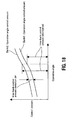
- the relationship between the normal control amount deviation and the target operation angle is calculated and stored as a deviation learned value for both banks. More specifically, as shown in Figure 18, the normal control amount deviation ( ⁇ H) at the current target operation angle is calculated and based on this deviation ⁇ H, the values in the operation angle/inter-bank control amount deviation table shown in Figure 19 are continually updated.
- the failure control amount for said one bank is calculated based on the target operation angle, the deviation learned value and the normal control amount for the other bank. More specifically, the operation angle/inter-bank control amount deviation table shown in Figure 19 is referenced based on the target operation angle, and the inter-bank deviation amount learned value corresponding to this target operation angle is found. And by adding or subtracting this inter-bank deviation amount learned value and the normal control amount for the other (normal) bank, the failure control value for said one bank (the one with the error) is calculated.
- a ratio can be used in place of said deviation.
- the relationship between the target operation angle and the ratio of normal control amounts for both banks is calculated and stored as a ratio learned value. More specifically, as shown in Figure 18, the normal control amount ratio for the current target operation angle is calculated, and based on this ratio, the values in the operation angle/inter-bank control amount ratio table shown in Figure 20 are continually updated. And when a sensor error occurs in one bank, at S14-C-1,2/B14-C-1,2, the failure control amount for said one bank is calculated based on the target operation angle, the ratio learned value, and the normal control amount for the other bank.
- the operation angle/inter-bank control amount ratio table shown in Figure 20 is referenced based on the target operation angle, the inter-bank control amount ratio learned value corresponding to this target operation angle is calculated, and the failure control value for said one bank (the one with the error) is calculated based on this inter-bank control amount ratio learned value and the normal control amount for the other (the normal one) bank.
- variable valve mechanism is applied to an intake valve, but the present invention can be similarly applied to a variable valve mechanism applied to an exhaust valve. Also, in said embodiments, the present invention is applied to lift operation angle changing mechanism 10, but it can also be applied to other variable valve mechanisms such as aforementioned phase changing mechanism 70.
- the actuator for the variable valve mechanism is not limited to an electrically-powered type that uses aforementioned motor 51, or the like, but could also be a hydraulically driven type.
- An embodiment of the present invention may provide a variable valve mechanism (lift operation angle changing mechanism 10/phase changing mechanism 70) that can continuously change lift characteristic amounts within a specified variable range for an intake valve (12) or an exhaust valve of an internal combustion engine; an actuator (motor 51) for driving this variable valve mechanism; and a detection means (operation angle sensor 53) for obtaining the detection value of said lift characteristic amounts (valve lift amount/operation angle/valve timing).
- a variable valve mechanism lift operation angle changing mechanism 10/phase changing mechanism 70
- An embodiment of the present invention may have a target value calculation means (S11/B11) for calculating the target value (target operation angle) of said lift characteristic amounts based on engine operating conditions; a first command value calculation means (S13/B13, etc.) for calculating the first command value (normal control amount) of said lift characteristic amounts based on said target value and detection value (actual operation angle); a second command value setting means (S14/B14, etc.) for setting the second command value (failure control amount) of said lift characteristic amounts; an error determination means (S12/B12, etc.) for determining errors in said detection means, and a command value switching means (B15, etc.) for outputting the first command value to the actuator when said detection means is normal, and for outputting the second command value to the actuator when an error occurs.
- a target value calculation means S11/B11
- first command value calculation means S13/B13, etc.
- first command value calculation means for calculating the first command value (normal control amount) of said lift characteristic amounts based on
- Said second command value setting means sets the second command value from within a range including intermediate values within said variable range.
- the failure control amount which is the second command value
- the failure control amount is changed according to the number of engine revolutions, indicating that an intermediate value within the variable range can be obtained as the second command value.
- the second command value is variably controlled, and an intermediate value can be obtained as this second command value.
- Figure 23 when ensuring a wide variable range for the valve lift amount, which is the lift characteristic amount, at setting condition 42 in which the valve lift amount is extremely low, the desired torque cannot be achieved in a high revolution range.
- Figure 24 shows operable range 43 in which the valve lift amount is at the minimum amount.
- the variable range used for feedback control is set at a narrow range in relation to a mechanical variable range from the maximum value, which is the mechanical connector position, to the minimum value, if the lift characteristic amount is open-controlled to the maximum or minimum values, there is a risk of hindering operability, so the control provided for in the present invention is very useful with respect to these variable valve mechanisms.
- the second command value setting means calculates the second command value based on the number of engine revolutions so that the second command value (failure control amount) is higher when the number of engine revolutions is higher.
- the second command value frailure control amount
- said second command value setting means calculates the second command value based on said target value so that the second command value (failure control amount) is higher when said target value (target operation angle) is higher.
- a learning means (S16/B16) may be provided that calculates and stores the relationship between said target value and the first command value during normal operation as a learned value.
- Said second command value setting means (S14B/S14A) calculates the second command value based on said target value and the learned value.
- a deviation learning means (S17/B17) is provided that calculates and stores the relationship between said target value and the deviation ⁇ H between the detection values for the two variable valve mechanisms as the deviation learned value during said normal operation.
- said second command value setting means (S14C-1,2/B14C-1,2) is configured so that the second command value for one variable valve mechanism is calculated based on said deviation learned value, the target value, and the first command value for the other variable valve mechanism.
- the second command value (failure control amount) for the bank that has the error is calculated based on the first command value for the other variable valve mechanism, or more specifically, on the feedback control amount for the normal bank, the second command value can be calculated with good precision in accordance with the operating conditions. Also, since the second command value is calculated based on the deviation between the first command values for the two variable valve mechanisms during normal operation, the deviation in lift characteristic amounts between both variable valve mechanisms as well as deterioration over time and changes in the environment can be favorably absorbed or offset to further improve operability when an error occurs.
- a ratio learning means (S17/B17) that calculates and stores the relationship between said target value and the ratio of the detection values for the two variable valve mechanisms as the ratio learned value during said normal operation.
- said second command value setting means (S14C-1,2/B14C-1,2) is configured so that the second command value for one variable valve mechanism is calculated based on said ratio learned value, the target value, and the first command value for the other variable valve mechanism.
- a variable valve mechanism to which the present invention may be advantageously applied is the lift operation angle changing mechanism 10 of Figure 1 for which the intake/exhaust valve lift amount and operation angle are continuously changeable.
- the air intake amount can be widely controlled without relying on a throttle valve, which allows for significant improvement of mileage and output performance, but at the same time, since the air intake amount greatly fluctuates based on changes in the lift characteristic amounts, using open control to control the minimum side or the maximum side of the variable range when an error occurs, while trying to ensure a wide variable rang may hinder the engine operability. Therefore, as explained above, the control provided by the present invention is extremely effective when an error occurs.
Landscapes
- Engineering & Computer Science (AREA)
- Mechanical Engineering (AREA)
- General Engineering & Computer Science (AREA)
- Chemical & Material Sciences (AREA)
- Combustion & Propulsion (AREA)
- Output Control And Ontrol Of Special Type Engine (AREA)
- Valve Device For Special Equipments (AREA)
- Valve-Gear Or Valve Arrangements (AREA)
- Fluid-Driven Valves (AREA)
Abstract
Description
- The present invention relates to an apparatus and method for controlling a variable valve mechanism and particularly, but not exclusively, a variable valve mechanism which, within a specified variable range, can continuously change the lift characteristic amounts for an internal combustion engine ("engine") intake valve or exhaust valve (hereafter "intake/exhaust valve"), such as the valve lift amount/operation angle, the valve timing, etc. The invention also relates to a variable valve mechanism, to an engine and to a vehicle.
- In the field of internal combustion engines for automobiles, a variety of variable valve mechanisms have conventionally been proposed, with changeable lift characteristic amounts such as the intake/exhaust valve lift amount, operation angle, and valve timing. Additional background on variable valve timing is described in Unexamined Japanese Patent Application Publication No. 2002-54466 and in U.S. Patent No. 6,843,226, entitled "Intake control apparatus for internal combustion engine," issued on January 18, 2005, both of which are commonly assigned.
- Feedback control is preferably performed based on the detected value of lift characteristic amounts to maintain lift characteristic amounts at their target values with good precision. As described in Unexamined Japanese Patent Application Publication No. 2002-54466, such feedback control technology is commonly known. Simply explained, target values for the lift characteristic amounts are calculated according to the engine operating conditions (load, number of revolutions, etc.), detection values equivalent to the actual lift characteristic amount values are obtained using an appropriate sensor, and the command value for the variable valve mechanism actuator is calculated based on the deviation of these target values and detection values.
- However, if feedback control is continued during a sensor error when the detection values cannot be accurately obtained due to sensor failure or error, the actual lift characteristic amount can be vastly different from the target value, and the risk of losing engine operability occurs. Therefore, in Unexamined Japanese Patent Application Publication No. 2002-54466, when a sensor error occurs, the system switches to an open control toward the maximum or minimum side of the variable range for the lift characteristic amounts.
- However, when the lift control amount variable range is further expanded for further improvement of mileage and output, operation angle
minimum value 40 may become extremely small as shown in Figure 21. Also, as shown in Figure 22, operation anglemaximum value 41 may become extremely large, causing an excess of residual gas within the cylinders. - It is an aim of the present invention to address one or more of the disadvantages associated with known mechanisms and methods.
- According to one aspect of the present invention, therefore, there is provided an apparatus for controlling a variable valve mechanism for an internal combustion engine intake valve or exhaust valve wherein a characteristic lift amount of the variable valve mechanism is continuously variable within a specified range, the apparatus comprising first actuator means for driving the variable valve mechanism and first detection means for detecting the characteristic lift amount set by the first actuator means in the variable valve mechanism, the apparatus being arranged to control the first actuator means to vary the characteristic lift amount within the specified range during a normal operation mode and to vary the characteristic lift amount within a sub-range of the specified range during an error operation mode when an error occurs in the first detection means.
- In one embodiment, the first detection means is operable to obtain a detection value indicative of the characteristic lift amount set by the first actuator means, and the apparatus further comprises target value calculation means for calculating a target value for the characteristic lift amount based on current engine operating conditions, first command value setting means for setting a first command value for the characteristic lift amount, based on the current target value and the detection value, second command value setting means for setting a second command value for the characteristic lift amount, error determination means for determining when an error occurs in first detection means, and command value switching means for outputting the first command value to the first actuator means during normal operation of the first detection means and for outputting the second command value to the first actuator means when an error occurs in the first detection means, wherein the second command value output from the second command value setting means is selected from within a sub-range of the specified range.
- In one embodiment, the sub-range is a sub-range of intermediate values of the specified range.
- In one embodiment the apparatus is arranged to control the first actuator means to vary the characteristic lift amount within the specified range during a normal operation mode based on a target value for current engine operating conditions and a current characteristic lift amount detected by the first detection means.
- In one embodiment the apparatus is arranged to control the first actuator means to vary the characteristic lift amount within the sub-range of the specified range during an error operation mode based on an engine revolution count.
- In one embodiment the apparatus is arranged to control the first actuator means to vary the characteristic lift amount within the sub-range of the specified range during an error operation mode based on a target value for current engine operating conditions.
- In one embodiment the apparatus is arranged to store a learned relationship value between a selected a target value for current engine operating conditions and a corresponding command value output to the first actuator means during the normal mode of operation, and wherein the apparatus is arranged to control the first actuator means to vary the characteristic lift amount within the specified range during an error operation mode based on the current target value and the learned relationship value.
- In one embodiment the second command value setting means is arranged to calculate the second command value based on an engine revolution count, optionally such that the second command value is higher when the engine revolution count is higher.
- In one embodiment the second command value setting means is arranged to calculate the second command value based on the calculated current target value, optionally such that the second command value is higher when the current target value is higher.
- In one embodiment, the apparatus further comprises learning means for calculating and storing a learned relationship value between a selected current target value and a corresponding first command value during normal operation, wherein the second command value setting means is arranged to calculate the second command value based on the current target value and the learned relationship value.
- In one embodiment, the apparatus further comprises deviation learning means for calculating and storing the relationship between a current target value and a deviation between at least two current detection values from at least two variable valve mechanisms as a learned deviation value during normal operation, wherein the second command value setting means is arranged to calculate a second command value for a first one of the variable valve mechanisms based on the current target value, the learned deviation value, and a first command value for a second one of the variable valve mechanisms.
- In one embodiment, the apparatus further comprises ratio learning means for calculating and storing the relationship between a current target value and a current ratio of detection values from at least two variable valve mechanisms as a learned ratio value during normal operation, wherein the second command value setting means is arranged to calculate a second command value for a first one of the variable valve mechanisms based on the current target value, the learned ratio value, and a first command value for a second one of the variable valve mechanisms.
- According to another aspect of the invention, there is provided a variable valve mechanism having an apparatus as described in one or more of the preceding paragraphs and comprising a lift operation angle changing mechanism including:
- a drive shaft rotatably linked to a crankshaft;
- an eccentric cam eccentrically provided on this drive shaft;
- a control shaft rotated by the first actuator means;
- a control cam eccentrically provided on this control shaft;
- a rocker arm eccentrically provided on this control cam;
- a rocking cam for lifting an intake valve or an exhaust valve;
- a first link for linking a first end of the rocker arm to the eccentric cam; and
- a second link for linking a second end of the rocker arm to the rocking cam
- According to yet another aspect of the invention, there is provided a variable valve mechanism in which lift characteristic amounts for an internal combustion engine intake valve or exhaust valve are continuously changeable within a specified variable range, an actuator to drive this variable valve mechanism, a detecting means for obtaining a detection value for said lift characteristic amounts, a target value calculation means which calculates a target value for said lift characteristic amounts based on engine operating conditions, a first command value calculation means for calculating a first command value for said lift characteristic amounts, based on said target value and detection value, a second command value setting means for setting a second command value for said lift characteristic amounts, an error determination means for determining an error for said detecting means, and a command value switching means for outputting the first command value to the actuator during normal operation of said detecting means, and outputting the second command value to the actuator during an error, said second command value setting means setting the second command value from within a range including intermediate values in said variable range.
- According to a further aspect of the invention, there is provided a variable valve mechanism control device comprising a variable valve mechanism for an internal combustion engine intake valve or exhaust valve, wherein a characteristic lift amount of the variable valve mechanism is continuously variable within a specified range, a first actuator to drive the variable valve mechanism and a first sensor to detect the current characteristic lift amount being set by the first actuator in the variable valve mechanism; wherein the variable valve mechanism control device is adapted to control the first actuator to vary the characteristic lift amount within the specified range during a normal operation mode and to vary the characteristic lift amount within a sub-range of the specified range during an error operation mode when an error occurs in the first sensor.
- According to a still further aspect of the invention, there is provided a variable valve mechanism control device, comprising a variable valve mechanism for an internal combustion engine intake valve or exhaust valve, wherein a characteristic lift amount of the variable valve mechanism is continuously variable within a specified range, an actuator to drive the variable valve mechanism, a detecting means for obtaining a detection value indicative of the current characteristic lift amount being set by the variable valve mechanism, a target value calculation means which calculates a current target value for the characteristic lift amount based on current engine operating conditions, a first command value setting means for setting a first command value output for the characteristic lift amount, based on the current target value and the detection value, a second command value setting means for setting a second command value output for the characteristic lift amount, an error determination means for determining when an error occurs in the detecting means and a command value switching means to couple the first command value output to the actuator during normal operation of the detecting means and to couple the second command value output to the actuator when an error occurs in the detecting means, wherein the second command value output from the second command value setting means is selected from within a sub-range of intermediate values in the specified range.
- According to another aspect of the invention there is provided an internal combustion engine including a variable valve mechanism for an intake valve or exhaust valve, wherein a characteristic lift amount of the variable valve mechanism is continuously variable within a specified range, and comprising an apparatus, mechanism or device as described in one or more of the preceding paragraphs.
- According to another aspect of the invention, there is provided a vehicle having an apparatus, a variable valve mechanism or an engine as described in one or more of the preceding paragraphs.
- Embodiments of the invention provide a variable valve mechanism which can continuously change internal combustion engine intake valve or exhaust valve lift characteristic amounts within a specified variable range, an actuator which drives said variable valve mechanism, and a detection means for obtaining detection values for said lift characteristic amounts. The lift characteristic amount target values are calculated based on the engine operating conditions, errors of said detection means are determined, and when said detection means is normal, a first command value for said lift characteristic amounts is calculated based on said target value and said detection value, and this first command value is output to the actuator. In contrast, when the detection means is abnormal, a lift characteristic amount second command value is set within a range including middle values in said variable range, and this second command value is output to the actuator.
- When the detection means is abnormal, the second command value selected from a range including middle values in the variable range is output to the actuator, enabling operation using mid-range values for the lift characteristic amounts.
- Advantageously, therefore the invention provides improving engine operability when an error occurs, compared to the conventional example in which lift characteristic amounts are maintained during an error at a maximum value or minimum value corresponding to a mechanical connector position.
- According to a further aspect of the invention there is provided a method of controlling a variable valve mechanism for an internal combustion engine intake valve or exhaust valve, wherein characteristic lift amounts of the valve are continuously variable within a specified range, having first actuator means for driving the variable valve and detection means for obtaining a detection value for the characteristic lift amounts, the method comprising calculating a target value for the lift characteristic amounts based on engine operating conditions, applying a first command value to the first actuator means for the lift characteristic amounts based on the target value and the detection value during normal operation of the detection means, and outputting a second command value to the first actuator means for the lift characteristic amounts when an error occurs in the detection means, wherein the second command value is selected from within a sub-range of the specified range, for example a sub-range of intermediate values of the specified range.
- According to a still further aspect of the invention, there is provided a variable valve mechanism control method, being a variable valve control method having a variable valve mechanism with which lift characteristic amounts for an internal combustion engine intake valve or exhaust valve are continuously changeable within a specified variable range, an actuator to drive this variable valve mechanism, and a detecting means for obtaining a detection value for said lift characteristic amounts, the method having a step which calculates a target value for said lift characteristic amounts based on engine operating conditions, a step for determining an error of said detecting means, a step for calculating a first command value for said lift characteristic amounts based on said target value and the detection value and outputting this first command value to the actuator during normal operation of said detecting mean and a step for setting a second command value for said lift characteristic amounts from within a range including intermediate values in said variable range and outputting this second command value to the actuator when an error occurs in said detecting means.
- In one embodiment, the sub-range of valve lift characteristic values is a sub-range of intermediate valve lift characteristic values of the specified variable range.
- In one embodiment, outputting a second command value to the actuator further comprises outputting a second command value to the actuator, where the second command value is selected from within the sub-range of valve lift characteristic values based on an engine revolution count.
- In one embodiment outputting a second command value to the actuator further comprises outputting a second command value to the actuator, where the second command value is selected from within the sub-range of valve lift characteristic values based on the target value for current engine operating conditions.
- In one embodiment, the method of further comprises storing a learned relationship value between a selected a target value for current engine operating conditions and a corresponding command value output to the actuator during the normal operation and outputting a second command value to the actuator, wherein the second command value is selected from within the specified variable range of valve lift characteristic values when an error is identified in the sensor based on the target value and the learned relationship value.
- In one embodiment, the method of claim further comprises storing a learned deviation value between the detection value of the sensor and a second detection value of a second sensor of a second variable valve mechanism at a selected target value for current engine operating conditions during normal operation; and outputting a second command value to a second actuator of the second variable valve mechanism when an error is identified in the second sensor, wherein the second command value is selected from within the specified variable range of valve lift characteristic values based on the target value, the learned deviation value, and the first command value for the actuator of the variable valve mechanism.
- In one embodiment, the method further comprises storing a learned ratio value between the detection value of the sensor and a second detection value of a second sensor of a second variable valve mechanism at a selected target value for current engine operating conditions during normal operation; and outputting a second command value to a second actuator of the second variable valve mechanism when an error is identified in the second sensor, wherein the second command value is selected from within the specified variable range of valve lift characteristic values based on the target value, the learned ratio value, and the first command value for the actuator of the variable valve mechanism
- The various aspects and embodiments mentioned in the preceding paragraphs may be used alone or in any suitable combination.
- The present invention will now be described, by way of example only, with reference to the accompanying drawings in which:
- Figure 1 is a simplified perspective drawing showing a lift operation angle changing mechanism, which is one example of a variable valve mechanism embodying the present invention;
- Figure 2 is a side view showing the pin and stopper that regulate the movable range for the control shaft in said lift operation angle changing mechanism;
- Figure 3 is a top view showing the movable range for the control shaft in said lift operation angle changing mechanism;
- Figure 4 is a control block diagram pertaining to the first embodiment of the present invention.
- Figure 5 is a control flowchart relating to said first embodiment;
- Figure 6 is an engine revolution count/operation angle control amount table used in said first embodiment;
- Figure 7 is a control block diagram pertaining to the second embodiment of the present invention;
- Figure 8 is a control flowchart pertaining to said second embodiment;
- Figure 9 is an operation angle/operation angle control amount table used in said second embodiment;
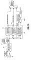
- Figure 10 is a control block diagram pertaining to the third embodiment of the present invention;
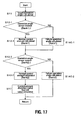
- Figure 11 is a control flowchart pertaining to said third embodiment;
- Figure 12 is an operation angle/operation angle control amount table used in said third embodiment;
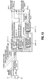
- Figure 13 is a control block diagram pertaining to the fourth embodiment of the present invention;
- Figure 14 is a control flowchart pertaining to said fourth embodiment;
- Figure 15 is an explanatory diagram including operation angle/operation angle control amount tables used by each bank in said fourth embodiment;
- Figure 16 is a control block diagram pertaining to the fifth embodiment of the present invention.
- Figure 17 is a control flowchart pertaining to said fifth embodiment;
- Figure 18 is an explanatory diagram showing the deviation and ratio of normal control amounts for both banks used in said fifth embodiment;
- Figure 19 is an explanatory diagram including an operation angle/inter-bank control amount deviation table used in said fifth embodiment;
- Figure 20 is an explanatory diagram including an operation angle/inter-bank control amount ratio table used as an alternative example of said fifth embodiment;
- Figure 21 is an explanatory diagram showing a sample setting for the minimum operation angle using said lift operation angle changing mechanism;
- Figure 22 is an explanatory diagram showing a sample setting for the maximum operation angle using said lift operation angle changing mechanism;
- Figure 23 is an explanatory diagram showing a sample setting for the valve lift amount using said lift operation angle changing mechanism; and
- Figure 24 is an explanatory diagram showing the operable range at the minimum valve lift amount using said lift operation angle changing mechanism.
- Figure 1 shows a lift operation
angle changing mechanism 10, in which both the operation angle and the valve lift amount (maximum lift amount) of anintake valve 12 can be continuously changed, and aphase changing mechanism 70, which can continuously change the valve timing (open/close timing) of anintake valve 12. Thesemechanisms intake valves 12 are provided for each cylinder, and avalve lifter 19 is provided at the top portion of eachintake valve 12. Above thesevalve lifters 19, ahollow drive shaft 13 with a lubricating oil path formed in its interior is located along the cylinder row direction. Rotational motive power is transmitted to thedrive shaft 13 from a crankshaft via thephase changing mechanism 70, and it is rotatably driven to link with the crankshaft. On thedrive shaft 13, a rockingcam 20 is externally fitted onto each cylinder such that rocking is possible. Each rockingcam 20 has one pair ofcam portions 20A, respectively, contacting the top surface of one pair ofvalve lifters 19 on each cylinder, and by rocking this rockingcam 20,intake valve 12 rises, that is, lifts, viacam portions 20A andvalve lifters 19. - The operation
angle changing mechanism 10 is eccentrically provided on the outer perimeter ofdrive shaft 13, and has aneccentric cam 15 rotating as one unit withdrive shaft 13, acontrol shaft 16 located along the cylinder row direction approximately parallel to thedrive shaft 13, acontrol cam 17 provided eccentrically on the outer perimeter of thecontrol shaft 16 and rotating as one unit therewith, arocker arm 18 externally fitted on the outer perimeter surface to form the cylinder surface ofcontrol cam 17 such that rocking is possible, a ring-shaped link (first link) 25 linking one end of therocker arm 18 to theeccentric cam 15, and a rod-shaped link (second link) 26 linking the other end of therocker arm 18 to the rockingcam 20. - One end of the ring-shaped
link 25 is externally fitted onto the outer perimeter surface to form the cylinder surface of theeccentric cam 15 such that relative rotation is possible, and the other end is connected to one end of therocker arm 18 via a first connectingpin 21 such that relative rotation is possible. One end of the rod-shapedlink 26 is connected via asecond pin 28 to the other end of therocker arm 18 such that relative rotation is possible, and the other end is connected via athird pin 29 to onecam portion 20A such that relative rotation is possible. - The axial center of the
eccentric cam 15 is eccentric to the axial center of thedrive shaft 13 by a specified amount, and the axial center of thecontrol cam 17 is eccentric to the axial center of thecontrol shaft 16 by a specified amount.Journal portion 20B of the rockingcam 20 and thecontrol shaft 16 are rotatably supported by a cylinder head via a bearing bracket (not shown). Thecontrol shaft 16 is rotatably driven by amotor 51, which serves as an actuator, and is held in a specified rotation position. In the present embodiment, aworm gear 52, provided on anoutput shaft 51a of themotor 51, is a simple structure that directly meshes with aworm gear wheel 50 fixed coaxially to one end of thecontrol shaft 16. - With this composition, when the
drive shaft 13 interlocks with the crankshaft and rotates, the ring-shapedlink 25 moves nearly parallel via theeccentric cam 15, therocker arm 18 rocks around the axial center ofcontrol cam 17, and the rockingcam 20 rocks via rod-shapedlink 26 causing theintake valve 12 to rise. In addition, varying the rotation angle of thecontrol shaft 16 will also change the axial center position of thecontrol cam 17, which is the rocking center of the rod-shapedlink 26, which will in turn change the posture of the rockingcam 20. Thus, the center phase (phase of open/close timing) of the operation angle of theintake valve 12 relative to the drive shaft stays generally stable, while the operation angle of the intake valve 12 (intake valve open/close timing) and the valve lift amount continually vary. - This type of operation
angle changing mechanism 10 is easily lubricated and has superior durability and reliability. Furthermore resistance to changing the operation angle is suppressed to a minimum because it has surface contact with the bearing portions for theeccentric cam 15 and thecontrol cam 17 as well as each pin. Also, because the rockingcam 20 for driving theintake valve 12 is placed coaxially with thedrive shaft 13, compared to a composition in which the driving cam is supported with a shaft that is different fromdrive shaft 13, there is superior control precision, the device itself is compact, and vehicle mounting ability is good. - Furthermore, since the rod-shaped
link 26 is placed so that it almost aligns with the upper and lower direction of the engine, the amount of extension to the side of the engine (left and right direction in Figure 1) is suppressed. In addition, there is little loss because the link mechanism is simple and does not use a spring or other energizing means in the transmission route from thedrive shaft 13 to the rockingcam 20, resulting in superior reliability and durability. - For the
phase changing mechanism 70, a rotation force from the crankshaft is transmitted via a timing belt (not shown) to provide relative rotation of thedrive shaft 13 and acam pulley 71, which is rotatably linked with the crankshaft and the center phase of the operation angle of theintake valve 12, which is the valve timing, is continuously changed in relation to the crankshaft. Inside ahousing 72 that rotates as one unit with thecam pulley 71 are installed a commonly known vane or spline mechanism and a hydraulic circuit for rotatably driving the drive shaft in the advance-angle or lag-angle directions. - A
control unit 54 has a function to memorize and execute various engine control processes including the control process described below, based on the input of detected signals, such as the engine revolution signal, engine load signal, cooling water temperature signal, and operating oil temperature signal. The angle of thecontrol shaft 16 corresponding to the lift characteristic amounts (valve lift amount and operating angle) of the lift operationangle changing mechanism 10 is detected by a potentiometer, such as an operation angle sensor (control shaft sensor) 53. - As shown in Figures 2 and 3, the
operation angle sensor 53 is supported by abracket 55, which is fixed to the cylinder head, and detects the rotation angle of thecontrol shaft 16, more specifically of apin 53a which rotates as one unit with thecontrol shaft 16 Theoperation angle sensor 53 outputs the detection value (signal) to thecontrol unit 54. Also, a rotationangle regulating pin 56 is fixed to the rear outer perimeter of thecontrol shaft 16. This rotationangle regulating pin 56 moves between a pair ofstoppers 57 provided on thebracket 55 in order to securecontrol shaft 16. In other words, rotatable angle range Δθ1, through which thecontrol shaft 16 can mechanically and physically rotate, is restricted and regulated from the minimum position to the maximum position by the rotationangle regulating pin 56 and the pair ofstoppers 57. Thus, the mechanical variable range of the lift characteristic amount is limited to a range from a minimum value to a maximum value. - Next, an explanation is provided for a specific embodiment of the control routine for the lift operation
angle changing mechanism 10. These control routines are memorized by saidcontrol unit 54 and are repeatedly executed for each specified period (for example, every 10ms). In the embodiment below, the operation angle is used to conveniently describe the lift characteristic amount, however, the valve lift amount could also be used. Also, the same reference numbers are essentially applied to the identical processes, so redundant explanations are omitted as appropriate. - The first embodiment is described with reference to Figures 4 through 6. In S (Step) 11/B (Block) 11, the target operation angle equivalent to the target value for the lift characteristic amount is computed/calculated based on accelerator opening APO that corresponds with the number of engine revolutions and the requested engine load (target value calculating means). Said number of engine revolutions is calculated based on, for example, a detection value from commonly known
crank angle sensor 31. The APO is detected byaccelerator opening sensor 32, for example, which detects the accelerator pedal opening. - At S12/B12, based on the target operation angle and the actual operation angle as a detection value of the lift characteristic amount, any error of the
operation angle sensor 53 as a detection means is detected/determined. The actual operation angle corresponds to theoperation angle sensor 53 detection value, and is calculated based on this detection value. Even when feedback control cannot be performed for a reason other than an error of the sensor itself, such as because of a communication problem, this S12/B12 determines an error. - At S13/B13, abnormal operation of
operation angle sensor 53, which is the detection means, is detected/determined in accordance with said target operation angle and the detected value for the lift characteristic amount, or the actual operation angle. The actual operation angle corresponds to the detected value forsensor 53, and is calculated based on this detected value. Even when feedback control cannot be performed for a reason other than an error in the sensor itself, such as a communication problem, Step S12/B12 is determined as an error.
At S14/B14, as shown in Figure 6, the failure (error) control amount, which is the second command value for the lift characteristic amount, is calculated with reference to the table showing the number of engine revolutions/operation angle control amount, which is pre-set and pre-stored, based on the number of engine revolutions. As shown in Figure 6, the higher the number of engine revolutions, the greater the air intake amount becomes, so the failure control amount is also set higher. - At
B 15, based on a determination normal or abnormal determined at S12/B12, either the normal control amount or the failure control amount is output as the operation angle control amount tomotor 51, which is actuator 51 for lift operation angle changing mechanism 10 (command value switching means). In other words, when normal, the normal control amount is output tomotor 51, and when abnormal, the failure control amount is output.Motor 51 operates in accordance with this operation angle control amount to change or maintain the rotation position ofcontrol shaft 16, thus controlling the valve lift amount and operation angle ofintake valve 12, which are the lift characteristic amounts. - According to the present embodiment, under normal operating conditions when
operation angle sensor 53 is operating normally, the normal control value is calculated based on the deviation between the target operation angle and the actual operation angle detected by operatingangle sensor 53, which is then output tomotor 51 to perform said feedback control. In contrast, when a sensor error occurs and feedback control cannot be performed based on the output (actual operation angle) ofsensor 53 due to abnormal operation or failure ofoperation angle sensor 53, open control is performed without using the actual operation angle. However, when the failure control amount output tomotor 51 when such a sensor error occurs is calculated based on the number of engine revolutions, as described above, this value changes according to the number of engine revolutions. In other words, it is calculated according to this number of engine revolutions from within a range including intermediate values in the lift characteristic amount variable range. - In this manner, an intermediate value within a variable range can be obtained for the failure control amount when a sensor error occurs, so operation using an intermediate value for the lift characteristic amount is possible. Therefore, engine operability can be improved even when an error occurs, compared to said conventional example in which the lift characteristic amount is maintained at a maximum value or minimum value corresponding to a mechanical connecting pin position, when an error occurs. Particularly, when the variable range for the lift characteristic amount is increased or when the variable range used for feedback control is set at a narrow range in relation to the variable range that is mechanically limited (for example, to a range corresponding to range Δθ1 for the control shaft shown in Figure 3), and if open control is performed of the maximum and minimum value of the mechanically variable range of the lift characteristic amount, this control is very useful for a variable valve mechanism that causes operation failures.
- Furthermore, in this first embodiment, because the lift characteristic amount is varied slightly based on only the number of engine revolutions, control is simple and stability is superior. This can be easily applied to existing devices, and because, unlike said conventional example, the lift characteristic value is not switched between the minimum value and the maximum value according to the operation range, a torque jump does not occurs due to this switching.
- For the second embodiment shown in Figures 7 through 9, at S14A/B14A, the failure control amount is calculated with reference to the pre-set and pre-stored operation angle/operation angle control amount table shown in Figure 9 based on the target operation angle. In other words, the failure control amount is calculated based on the target operation angle. As shown in Figure 9, the failure control amount is basically set such that it increases as the target operation angle increases, and decreases as the target operation angle decreases, so that the operation angle is follows the target operation value when a failure occurs.
- In the third embodiment shown in Figures 10 through 12, at S16/B16, the learned value for the failure control amount corresponding to the actual operation angle is calculated and stored based on the actual operation angle and the normal control amount calculated at S13/B13. More specifically, the previously set and stored values in the operation angle/operation angle control amount table shown in Figure 12 is updated one after another. And at S14B/B14B, the failure control amount is calculated based on the target operation angle and the learned value. More specifically, the failure control amount is obtained by looking up values from the table in Figure 12, which has been continually updated at S16/B16 based on the target operation angle.
- Thus, according to the third embodiment, when feedback control is performed under normal conditions, learned values are calculated based on the actual operation angle and the normal control amount, and the learned value is used to obtain the failure control amount when a failure occurs so the effects of deterioration over time or fluctuations occurring when the failure control amount is calculated can be absorbed or offset, resulting in improved precision when setting the failure control amount when a sensor error occurs.
- For the fourth and fifth embodiments described below, lift operation
angle changing mechanism 10 has been applied respectively to left andright banks control shaft 16,operation angle sensor 53,motor 51 etc. have each been provided for lift operationangle changing mechanism 10 on each bank. A "-1" is placed after the reference numbers for the contents of the process corresponding to one of the banks (bank 1) and a "-2" is placed after the reference numbers for the contents of the process corresponding to the other bank (bank 2) and redundant explanations are omitted as appropriate. - In the fourth embodiment shown in Figures 13 though 15, the same control process that is used in said Embodiment 3 is applied to the lift operation
angle changing mechanisms 10 onbank 1 andbank 2, respectively. Therefore, as shown in Figure 15, a control amount table is pre-set and pre-stored individually forbanks - A fifth embodiment is shown in Figures 16 through 20. When sensors are normal for both banks, at S17/B17, the relationship between the normal control amount deviation and the target operation angle is calculated and stored as a deviation learned value for both banks. More specifically, as shown in Figure 18, the normal control amount deviation (ΔH) at the current target operation angle is calculated and based on this deviation ΔH, the values in the operation angle/inter-bank control amount deviation table shown in Figure 19 are continually updated.
- And, when a sensor error occurs in one bank, at S-14C-1, 2/B-14C-1,2, the failure control amount for said one bank is calculated based on the target operation angle, the deviation learned value and the normal control amount for the other bank. More specifically, the operation angle/inter-bank control amount deviation table shown in Figure 19 is referenced based on the target operation angle, and the inter-bank deviation amount learned value corresponding to this target operation angle is found. And by adding or subtracting this inter-bank deviation amount learned value and the normal control amount for the other (normal) bank, the failure control value for said one bank (the one with the error) is calculated.
- As an alternative example of this fifth embodiment, a ratio can be used in place of said deviation. In other words, when sensors for both banks are normal, at S17/B17, the relationship between the target operation angle and the ratio of normal control amounts for both banks is calculated and stored as a ratio learned value. More specifically, as shown in Figure 18, the normal control amount ratio for the current target operation angle is calculated, and based on this ratio, the values in the operation angle/inter-bank control amount ratio table shown in Figure 20 are continually updated. And when a sensor error occurs in one bank, at S14-C-1,2/B14-C-1,2, the failure control amount for said one bank is calculated based on the target operation angle, the ratio learned value, and the normal control amount for the other bank. More specifically, the operation angle/inter-bank control amount ratio table shown in Figure 20 is referenced based on the target operation angle, the inter-bank control amount ratio learned value corresponding to this target operation angle is calculated, and the failure control value for said one bank (the one with the error) is calculated based on this inter-bank control amount ratio learned value and the normal control amount for the other (the normal one) bank.
- Next, an explanation is provided of the unique technological concept and operational effect of the present invention with respect to the aforementioned embodiments. However, the present invention is not limited to the content of said embodiments, but includes a variety of modifications and alterations. For example, in the aforementioned embodiments, the variable valve mechanism is applied to an intake valve, but the present invention can be similarly applied to a variable valve mechanism applied to an exhaust valve. Also, in said embodiments, the present invention is applied to lift operation
angle changing mechanism 10, but it can also be applied to other variable valve mechanisms such as aforementionedphase changing mechanism 70. In addition, the actuator for the variable valve mechanism is not limited to an electrically-powered type that usesaforementioned motor 51, or the like, but could also be a hydraulically driven type. - An embodiment of the present invention may provide a variable valve mechanism (lift operation
angle changing mechanism 10/phase changing mechanism 70) that can continuously change lift characteristic amounts within a specified variable range for an intake valve (12) or an exhaust valve of an internal combustion engine; an actuator (motor 51) for driving this variable valve mechanism; and a detection means (operation angle sensor 53) for obtaining the detection value of said lift characteristic amounts (valve lift amount/operation angle/valve timing). An embodiment of the present invention may have a target value calculation means (S11/B11) for calculating the target value (target operation angle) of said lift characteristic amounts based on engine operating conditions; a first command value calculation means (S13/B13, etc.) for calculating the first command value (normal control amount) of said lift characteristic amounts based on said target value and detection value (actual operation angle); a second command value setting means (S14/B14, etc.) for setting the second command value (failure control amount) of said lift characteristic amounts; an error determination means (S12/B12, etc.) for determining errors in said detection means, and a command value switching means (B15, etc.) for outputting the first command value to the actuator when said detection means is normal, and for outputting the second command value to the actuator when an error occurs. - Said second command value setting means sets the second command value from within a range including intermediate values within said variable range. For example, in said first embodiment, as shown in Figure 6, the failure control amount, which is the second command value, is changed according to the number of engine revolutions, indicating that an intermediate value within the variable range can be obtained as the second command value. Likewise, in other embodiments, the second command value is variably controlled, and an intermediate value can be obtained as this second command value.
- Therefore, operation using intermediate values for lift characteristic amounts becomes possible even when an error occurs in the detection means by setting an intermediate value within the variable range as a second command value. Therefore, engine operability during an error can be improved, compared to said conventional example in which lift characteristic amounts are maintained during an error at a maximum value or minimum value corresponding to a mechanical connector position. In other words, even during an error, stabilized operability can be ensured within a wide range of engine operation (rotation/load range).
- For example, as shown in Figure 23, when ensuring a wide variable range for the valve lift amount, which is the lift characteristic amount, at setting
condition 42 in which the valve lift amount is extremely low, the desired torque cannot be achieved in a high revolution range. For a reference, Figure 24 showsoperable range 43 in which the valve lift amount is at the minimum amount. In addition, even when the variable range used for feedback control is set at a narrow range in relation to a mechanical variable range from the maximum value, which is the mechanical connector position, to the minimum value, if the lift characteristic amount is open-controlled to the maximum or minimum values, there is a risk of hindering operability, so the control provided for in the present invention is very useful with respect to these variable valve mechanisms. - Preferably, as in the first embodiment shown in Figures 4 through 6, the second command value setting means (S14/B14) calculates the second command value based on the number of engine revolutions so that the second command value (failure control amount) is higher when the number of engine revolutions is higher. Thus, by providing a simple calculation process based on the number of engine revolutions, insufficient torque that takes place during high engine revolution when an error occurs can be effectively eliminated. (See Figure 23).
- Or for the second embodiment shown in Figures 7 through 9, said second command value setting means (S 14A/S 14B) calculates the second command value based on said target value so that the second command value (failure control amount) is higher when said target value (target operation angle) is higher. Thus, by calculating the lift characteristic amounts based on target values even when an error occurs, favorable operation becomes possible in a wide range of operation. In addition, since the target value used during normal operation is being utilized, the burden placed on control is small and application to existing control devices becomes easier.
- Or for the third embodiment shown in Figures 10 through 12, a learning means (S16/B16) may be provided that calculates and stores the relationship between said target value and the first command value during normal operation as a learned value. Said second command value setting means (S14B/S14A) calculates the second command value based on said target value and the learned value. Thus by learning the relationship between the target value and the first command value during normal operation, and by using this learned value and the target value to calculate the second command value when an error occurs, the effects of deterioration over time and fluctuations can be absorbed or offset, resulting in improved precision when setting the second command value and increased operability when an error occurs.
- As in the case of the fourth embodiment shown in Figures 13 though 15, this type of control can easily be applied to respective variable valve mechanisms provided for each
bank - As in the case of the fifth embodiment shown in Figures 16 through 20, when at least two variable valve mechanisms (10) are provided and controlled to achieve the same target value (target operation angle), a deviation learning means (S17/B17) is provided that calculates and stores the relationship between said target value and the deviation ΔH between the detection values for the two variable valve mechanisms as the deviation learned value during said normal operation. And said second command value setting means (S14C-1,2/B14C-1,2) is configured so that the second command value for one variable valve mechanism is calculated based on said deviation learned value, the target value, and the first command value for the other variable valve mechanism.
- Because the second command value (failure control amount) for the bank that has the error is calculated based on the first command value for the other variable valve mechanism, or more specifically, on the feedback control amount for the normal bank, the second command value can be calculated with good precision in accordance with the operating conditions. Also, since the second command value is calculated based on the deviation between the first command values for the two variable valve mechanisms during normal operation, the deviation in lift characteristic amounts between both variable valve mechanisms as well as deterioration over time and changes in the environment can be favorably absorbed or offset to further improve operability when an error occurs.
- And as is the case with the alternative example for the fifth embodiment shown in Figures 16 through 20, a ratio learning means (S17/B17) is provided that calculates and stores the relationship between said target value and the ratio of the detection values for the two variable valve mechanisms as the ratio learned value during said normal operation. And said second command value setting means (S14C-1,2/B14C-1,2) is configured so that the second command value for one variable valve mechanism is calculated based on said ratio learned value, the target value, and the first command value for the other variable valve mechanism. Thus, by using a ratio, the operability can be significantly improved when an error occurs, as was the case when using said deviation.
- A variable valve mechanism to which the present invention may be advantageously applied is the lift operation
angle changing mechanism 10 of Figure 1 for which the intake/exhaust valve lift amount and operation angle are continuously changeable. When using such a lift operationangle changing mechanism 10, the air intake amount can be widely controlled without relying on a throttle valve, which allows for significant improvement of mileage and output performance, but at the same time, since the air intake amount greatly fluctuates based on changes in the lift characteristic amounts, using open control to control the minimum side or the maximum side of the variable range when an error occurs, while trying to ensure a wide variable rang may hinder the engine operability. Therefore, as explained above, the control provided by the present invention is extremely effective when an error occurs. - The present application claims priority from Japanese Patent Application No. 2004-352510, filed on 4th December 2004, the entire content of which is incorporated herein by reference. Although specific embodiments have been illustrated and described herein, it will be appreciated by those skilled in the art that any arrangement, which is calculated to achieve the same purpose, may be substituted for the specific embodiment shown. This application is intended to cover any adaptations or variations of the present invention. Therefore, it is manifestly intended that this invention be limited only by the claims and the equivalents thereof.
Claims (16)
- An apparatus for controlling a variable valve mechanism for an internal combustion engine intake valve or exhaust valve wherein a characteristic lift amount of the variable valve mechanism is continuously variable within a specified range, the apparatus comprising:first actuator means for driving the variable valve mechanism; andfirst detection means for detecting the characteristic lift amount set by the first actuator means in the variable valve mechanism;the apparatus being arranged to control the first actuator means to vary the characteristic lift amount within the specified range during a normal operation mode and to vary the characteristic lift amount within a sub-range of the specified range during an error operation mode when an error occurs in the first detection means.
- An apparatus as claimed in claim 1 wherein the first detection means is operable to obtain a detection value indicative of the characteristic lift amount set by the first actuator means, the apparatus further comprising:target value calculation means for calculating a target value for the characteristic lift amount based on current engine operating conditions;first command value setting means for setting a first command value for the characteristic lift amount, based on the current target value and the detection value;second command value setting means for setting a second command value for the characteristic lift amount;error determination means for determining when an error occurs in first detection means; andcommand value switching means for outputting the first command value to the first actuator means during normal operation of the first detection means and for outputting the second command value to the first actuator means when an error occurs in the first detection means, wherein the second command value output from the second command value setting means is selected from within a sub-range of the specified range.
- An apparatus as claimed in claim 1 or claim 2, wherein the sub-range is a sub-range of intermediate values of the specified range.
- An apparatus as claimed in any of claims 1 to 3, wherein the apparatus is arranged to control the first actuator means to vary the characteristic lift amount within the specified range during a normal operation mode based on a target value for current engine operating conditions and a current characteristic lift amount detected by the first detection means.
- An apparatus as claimed in any preceding claim wherein the apparatus is arranged to control the first actuator means to vary the characteristic lift amount within the sub-range of the specified range during an error operation mode based on an engine revolution count.
- An apparatus as claimed in any preceding claim, wherein the apparatus is arranged to control the first actuator means to vary the characteristic lift amount within the sub-range of the specified range during an error operation mode based on a target value for current engine operating conditions.
- An apparatus as claimed in any preceding claim wherein the apparatus is arranged to store a learned relationship value between a selected a target value for current engine operating conditions and a corresponding command value output to the first actuator means during the normal mode of operation, and wherein the apparatus is arranged to control the first actuator means to vary the characteristic lift amount within the specified range during an error operation mode based on the current target value and the learned relationship value.
- An apparatus as claimed in any of claims 2 to 7 wherein the second command value setting means is arranged to calculate the second command value based on an engine revolution count, optionally such that the second command value is higher when the engine revolution count is higher.
- An apparatus as claimed in any of claims 2 to 8, wherein the second command value setting means calculates the second command value based on the calculated current target value, optionally such that the second command value is higher when the current target value is higher.
- An apparatus as claimed in any of claims 2 to 9 further comprising learning means for calculating and storing a learned relationship value between a selected current target value and a corresponding first command value during normal operation;
wherein the second command value setting means is arranged to calculate the second command value based on the current target value and the learned relationship value. - An apparatus as claimed in any of claims 2 to 10 further comprising:deviation learning means for calculating and storing the relationship between a current target value and a deviation between at least two current detection values from at least two variable valve mechanisms as a learned deviation value during normal operation;wherein the second command value setting means is arranged to calculate a second command value for a first one of the variable valve mechanisms based on the current target value, the learned deviation value, and a first command value for a second one of the variable valve mechanisms.
- An apparatus as claimed in any of claims 2 to 11 further comprising:ratio learning means for calculating and storing the relationship between a current target value and a current ratio of detection values from at least two variable valve mechanisms as a learned ratio value during normal operation;wherein the second command value setting means is arranged to calculate a second command value for a first one of the variable valve mechanisms based on the current target value, the learned ratio value, and a first command value for a second one of the variable valve mechanisms.
- A variable valve mechanism having an apparatus as claimed in any preceding claim and including a lift operation angle changing mechanism comprising:a drive shaft rotatably linked to a crankshaft;an eccentric cam eccentrically provided on this drive shaft;a control shaft rotated by the first actuator means;a control cam eccentrically provided on this control shaft;a rocker arm eccentrically provided on this control cam;a rocking cam for lifting an intake valve or an exhaust valve;a first link for linking a first end of the rocker arm to the eccentric cam; anda second link for linking a second end of the rocker arm to the rocking cam.
- An internal combustion engine, comprising an apparatus and/or mechanism as claimed in any preceding claim.
- A vehicle having an apparatus, mechanism or engine as claimed in any preceding claim.
- A method of controlling a variable valve mechanism for an internal combustion engine intake valve or exhaust valve, wherein characteristic lift amounts of the valve are continuously variable within a specified range, having actuator means for driving the variable valve and detection means for obtaining a detection value for the characteristic lift amounts, the method comprising:calculating a target value for the lift characteristic amounts based on engine operating conditions;applying a first command value to the actuator means for the lift characteristic amounts based on the target value and the detection value during normal operation of the detection means; andoutputting a second command value to the actuator means for the lift characteristic amounts when an error occurs in the detection means, wherein the second command value is selected from within a sub-range of the specified range, for example a sub-range of intermediate values of the specified range.
Applications Claiming Priority (1)
| Application Number | Priority Date | Filing Date | Title |
|---|---|---|---|
| JP2004352510A JP4096939B2 (en) | 2004-12-06 | 2004-12-06 | Control apparatus and control method for variable valve mechanism |
Publications (2)
| Publication Number | Publication Date |
|---|---|
| EP1669560A1 true EP1669560A1 (en) | 2006-06-14 |
| EP1669560B1 EP1669560B1 (en) | 2008-09-03 |
Family
ID=36123122
Family Applications (1)
| Application Number | Title | Priority Date | Filing Date |
|---|---|---|---|
| EP05257456A Expired - Lifetime EP1669560B1 (en) | 2004-12-06 | 2005-12-03 | Apparatus and method for controlling a variable valve mechanism |
Country Status (7)
| Country | Link |
|---|---|
| US (1) | US7293537B2 (en) |
| EP (1) | EP1669560B1 (en) |
| JP (1) | JP4096939B2 (en) |
| KR (1) | KR100663215B1 (en) |
| CN (1) | CN100381687C (en) |
| AT (1) | ATE407284T1 (en) |
| DE (1) | DE602005009467D1 (en) |
Cited By (6)
| Publication number | Priority date | Publication date | Assignee | Title |
|---|---|---|---|---|
| EP1950395A1 (en) * | 2007-01-24 | 2008-07-30 | HONDA MOTOR CO., Ltd. | An intake air control for an internal-combustion engine |
| WO2008142559A1 (en) * | 2007-05-24 | 2008-11-27 | Toyota Jidosha Kabushiki Kaisha | Control apparatus and control method for internal combustion engine |
| EP2098693A1 (en) * | 2008-03-03 | 2009-09-09 | Kawasaki Jukogyo Kabushiki Kaisha | Engine and vehicle comprising engine |
| EP2080872A3 (en) * | 2008-01-15 | 2010-10-27 | Yamaha Hatsudoki Kabushiki Kaisha | Variable valve device for engine |
| WO2011154837A1 (en) * | 2010-06-10 | 2011-12-15 | Toyota Jidosha Kabushiki Kaisha | Method and apparatus for controlling a variable valve system |
| WO2011154838A1 (en) * | 2010-06-10 | 2011-12-15 | Toyota Jidosha Kabushiki Kaisha | Method and apparatus for controlling a variable valve system |
Families Citing this family (13)
| Publication number | Priority date | Publication date | Assignee | Title |
|---|---|---|---|---|
| KR100866916B1 (en) * | 2006-12-14 | 2008-11-06 | (주) 메크로시스템엔지니어링 | Sensor automatic switching control device and control method |
| JP4583362B2 (en) * | 2006-12-21 | 2010-11-17 | 日立オートモティブシステムズ株式会社 | Valve control device for internal combustion engine |
| JP4655036B2 (en) | 2006-12-27 | 2011-03-23 | トヨタ自動車株式会社 | Control device for variable valve mechanism |
| KR100969026B1 (en) * | 2008-05-22 | 2010-07-09 | 현대자동차주식회사 | Continuously variable valve lift device in the engine |
| US8225758B2 (en) | 2008-05-22 | 2012-07-24 | Hyundai Motor Company | Continuously variable valve lift system for engines and controlling method thereof |
| JP4525797B2 (en) * | 2008-05-23 | 2010-08-18 | トヨタ自動車株式会社 | Abnormality judgment device for valve characteristic change mechanism |
| CN101403326A (en) * | 2008-06-16 | 2009-04-08 | 奇瑞汽车股份有限公司 | Variable air valve lift range mechanism of internal combustion engine |
| JP5302844B2 (en) * | 2008-11-21 | 2013-10-02 | 本田技研工業株式会社 | Control device for internal combustion engine |
| JP5201274B2 (en) * | 2010-01-15 | 2013-06-05 | トヨタ自動車株式会社 | Valve working angle variable system |
| CN104153839B (en) * | 2014-08-29 | 2017-01-11 | 长城汽车股份有限公司 | Method for self-inspection of continuously variable valve lift mechanism |
| CN104612779B (en) * | 2014-11-28 | 2017-06-20 | 长城汽车股份有限公司 | For the variable air valve lift range mechanism and its control method of vehicle |
| KR101755466B1 (en) | 2015-12-14 | 2017-07-07 | 현대자동차 주식회사 | Method of controlling continuous variable valve timing system for limp-home |
| KR101796255B1 (en) * | 2016-06-30 | 2017-11-10 | 주식회사 현대케피코 | Continuously variable valve duration system and operating method thereof |
Citations (8)
| Publication number | Priority date | Publication date | Assignee | Title |
|---|---|---|---|---|
| JP2002054466A (en) | 2000-08-08 | 2002-02-20 | Unisia Jecs Corp | Variable valve train for internal combustion engine |
| EP1258601A2 (en) * | 2001-05-09 | 2002-11-20 | Unisia Jecs Corporation | Variable-valve-actuation apparatus for internal combustion engine |
| EP1279816A2 (en) * | 2001-07-26 | 2003-01-29 | Unisia Jecs Corporation | Apparatus and method for controlling an internal combustion engine |
| EP1288453A2 (en) * | 2001-08-29 | 2003-03-05 | Nissan Motor Company, Limited | Variable valve operating system of internal combustion engine enabling variation of valve-lift characteristic and phase |
| EP1300551A2 (en) * | 2001-10-03 | 2003-04-09 | Nissan Motor Company, Limited | Variable valve operating system of internal combustion engine enabling variation of valve-lift characteristic |
| US6694934B1 (en) * | 2002-11-22 | 2004-02-24 | Eaton Corporation | Variable valve actuator for internal combustion engine |
| EP1403487A2 (en) * | 2002-09-24 | 2004-03-31 | Nissan Motor Company, Limited | Control system and method for an internal combustion engine having a VVT device |
| US6843226B2 (en) | 2002-12-16 | 2005-01-18 | Nissan Motor Co., Ltd. | Intake control apparatus for internal combustion engine |
Family Cites Families (4)
| Publication number | Priority date | Publication date | Assignee | Title |
|---|---|---|---|---|
| JP3873834B2 (en) * | 2002-07-22 | 2007-01-31 | 日産自動車株式会社 | Intake valve drive control device for internal combustion engine |
| DE10397025B3 (en) * | 2002-10-25 | 2021-10-21 | Denso Corporation | Variable valve timing control device of an internal combustion engine |
| JP3985696B2 (en) * | 2003-02-28 | 2007-10-03 | 日産自動車株式会社 | Variable valve operating device for internal combustion engine |
| JP4075846B2 (en) * | 2004-04-26 | 2008-04-16 | 日産自動車株式会社 | Variable valve operating system for multi-cylinder internal combustion engine |
-
2004
- 2004-12-06 JP JP2004352510A patent/JP4096939B2/en not_active Expired - Fee Related
-
2005
- 2005-12-03 EP EP05257456A patent/EP1669560B1/en not_active Expired - Lifetime
- 2005-12-03 AT AT05257456T patent/ATE407284T1/en not_active IP Right Cessation
- 2005-12-03 DE DE602005009467T patent/DE602005009467D1/en not_active Expired - Lifetime
- 2005-12-05 KR KR1020050117318A patent/KR100663215B1/en not_active Expired - Fee Related
- 2005-12-06 CN CNB200510129750XA patent/CN100381687C/en not_active Expired - Fee Related
- 2005-12-06 US US11/295,170 patent/US7293537B2/en not_active Expired - Fee Related
Patent Citations (8)
| Publication number | Priority date | Publication date | Assignee | Title |
|---|---|---|---|---|
| JP2002054466A (en) | 2000-08-08 | 2002-02-20 | Unisia Jecs Corp | Variable valve train for internal combustion engine |
| EP1258601A2 (en) * | 2001-05-09 | 2002-11-20 | Unisia Jecs Corporation | Variable-valve-actuation apparatus for internal combustion engine |
| EP1279816A2 (en) * | 2001-07-26 | 2003-01-29 | Unisia Jecs Corporation | Apparatus and method for controlling an internal combustion engine |
| EP1288453A2 (en) * | 2001-08-29 | 2003-03-05 | Nissan Motor Company, Limited | Variable valve operating system of internal combustion engine enabling variation of valve-lift characteristic and phase |
| EP1300551A2 (en) * | 2001-10-03 | 2003-04-09 | Nissan Motor Company, Limited | Variable valve operating system of internal combustion engine enabling variation of valve-lift characteristic |
| EP1403487A2 (en) * | 2002-09-24 | 2004-03-31 | Nissan Motor Company, Limited | Control system and method for an internal combustion engine having a VVT device |
| US6694934B1 (en) * | 2002-11-22 | 2004-02-24 | Eaton Corporation | Variable valve actuator for internal combustion engine |
| US6843226B2 (en) | 2002-12-16 | 2005-01-18 | Nissan Motor Co., Ltd. | Intake control apparatus for internal combustion engine |
Cited By (12)
| Publication number | Priority date | Publication date | Assignee | Title |
|---|---|---|---|---|
| EP1950395A1 (en) * | 2007-01-24 | 2008-07-30 | HONDA MOTOR CO., Ltd. | An intake air control for an internal-combustion engine |
| WO2008142559A1 (en) * | 2007-05-24 | 2008-11-27 | Toyota Jidosha Kabushiki Kaisha | Control apparatus and control method for internal combustion engine |
| RU2429362C2 (en) * | 2007-05-24 | 2011-09-20 | Тойота Дзидося Кабусики Кайся | Ice control device |
| US8050850B2 (en) | 2007-05-24 | 2011-11-01 | Toyota Jidosha Kabushiki Kaisha | Control apparatus and control method for internal combustion engine |
| CN101680370B (en) * | 2007-05-24 | 2013-03-13 | 丰田自动车株式会社 | Control apparatus and control method for internal combustion engine |
| EP2080872A3 (en) * | 2008-01-15 | 2010-10-27 | Yamaha Hatsudoki Kabushiki Kaisha | Variable valve device for engine |
| US7938100B2 (en) | 2008-01-15 | 2011-05-10 | Yamaha Hatsudoki Kabushiki Kaisha | Variable valve device for engine |
| EP2098693A1 (en) * | 2008-03-03 | 2009-09-09 | Kawasaki Jukogyo Kabushiki Kaisha | Engine and vehicle comprising engine |
| US8156908B2 (en) | 2008-03-03 | 2012-04-17 | Kawasaki Jukogyo Kabushiki Kaisha | Engine and vehicle comprising engine |
| WO2011154837A1 (en) * | 2010-06-10 | 2011-12-15 | Toyota Jidosha Kabushiki Kaisha | Method and apparatus for controlling a variable valve system |
| WO2011154838A1 (en) * | 2010-06-10 | 2011-12-15 | Toyota Jidosha Kabushiki Kaisha | Method and apparatus for controlling a variable valve system |
| EP2799697A1 (en) * | 2010-06-10 | 2014-11-05 | Toyota Jidosha Kabushiki Kaisha | Variable valve timing apparatus for internal combustion engine and control method thereof |
Also Published As
| Publication number | Publication date |
|---|---|
| US20060130787A1 (en) | 2006-06-22 |
| JP4096939B2 (en) | 2008-06-04 |
| KR100663215B1 (en) | 2007-01-02 |
| JP2006161631A (en) | 2006-06-22 |
| CN100381687C (en) | 2008-04-16 |
| US7293537B2 (en) | 2007-11-13 |
| CN1786444A (en) | 2006-06-14 |
| ATE407284T1 (en) | 2008-09-15 |
| EP1669560B1 (en) | 2008-09-03 |
| DE602005009467D1 (en) | 2008-10-16 |
| KR20060063718A (en) | 2006-06-12 |
Similar Documents
| Publication | Publication Date | Title |
|---|---|---|
| EP1669560B1 (en) | Apparatus and method for controlling a variable valve mechanism | |
| JP4600074B2 (en) | Variable compression ratio device for internal combustion engine | |
| EP1403487B1 (en) | Control system and method for an internal combustion engine having a VVT device | |
| MXPA06012498A (en) | Controller of internal combustion engine. | |
| US20080289605A1 (en) | Actuator control apparatus | |
| EP2660434B1 (en) | Reference angle detecting device | |
| JP4151602B2 (en) | Reference position learning device for variable valve mechanism | |
| JP3975246B2 (en) | Variable valve operating device for internal combustion engine | |
| US7513229B2 (en) | Apparatus for and method of controlling variable valve mechanism | |
| JP4027536B2 (en) | Variable valve operating device for internal combustion engine | |
| EP2189632B1 (en) | Control system for internal combustion engine | |
| JP4157783B2 (en) | Multi-cylinder internal combustion engine and lift adjustment method thereof. | |
| JP2009299503A (en) | Failure determination device for variable valve mechanism and control device for internal combustion engine equipped with the same | |
| JP2000314329A (en) | Processing device for operation sensor failure in variable valve train of internal combustion engine | |
| JP2005023874A (en) | Air-fuel ratio control device for internal combustion engine with variable valve mechanism | |
| CN1834411A (en) | Internal combustion engine | |
| JP4880556B2 (en) | Control device for variable valve mechanism | |
| JP4330939B2 (en) | Control device for variable valve mechanism | |
| JP3976002B2 (en) | Intake valve drive control device for internal combustion engine | |
| KR101472687B1 (en) | Learning method and apparatus for contolling a Continuous Variable Valve Lift system | |
| JP4865670B2 (en) | Variable valve opening characteristics valve gear | |
| JP2004324592A (en) | A start control device and a start control method for an internal combustion engine. | |
| JP2010019180A (en) | Variable valve gear for internal combustion engine | |
| JP2806081B2 (en) | Control device for internal combustion engine | |
| JP2001263103A (en) | Control device for variable valve train of internal combustion engine |
Legal Events
| Date | Code | Title | Description |
|---|---|---|---|
| PUAI | Public reference made under article 153(3) epc to a published international application that has entered the european phase |
Free format text: ORIGINAL CODE: 0009012 |
|
| AK | Designated contracting states |
Kind code of ref document: A1 Designated state(s): AT BE BG CH CY CZ DE DK EE ES FI FR GB GR HU IE IS IT LI LT LU LV MC NL PL PT RO SE SI SK TR |
|
| AX | Request for extension of the european patent |
Extension state: AL BA HR MK YU |
|
| 17P | Request for examination filed |
Effective date: 20061214 |
|
| AKX | Designation fees paid |
Designated state(s): AT BE BG CH CY CZ DE DK EE ES FI FR GB GR HU IE IS IT LI LT LU LV MC NL PL PT RO SE SI SK TR |
|
| GRAP | Despatch of communication of intention to grant a patent |
Free format text: ORIGINAL CODE: EPIDOSNIGR1 |
|
| GRAS | Grant fee paid |
Free format text: ORIGINAL CODE: EPIDOSNIGR3 |
|
| GRAA | (expected) grant |
Free format text: ORIGINAL CODE: 0009210 |
|
| AK | Designated contracting states |
Kind code of ref document: B1 Designated state(s): AT BE BG CH CY CZ DE DK EE ES FI FR GB GR HU IE IS IT LI LT LU LV MC NL PL PT RO SE SI SK TR |
|
| REG | Reference to a national code |
Ref country code: GB Ref legal event code: FG4D |
|
| REG | Reference to a national code |
Ref country code: CH Ref legal event code: EP |
|
| REG | Reference to a national code |
Ref country code: IE Ref legal event code: FG4D |
|
| REF | Corresponds to: |
Ref document number: 602005009467 Country of ref document: DE Date of ref document: 20081016 Kind code of ref document: P |
|
| PG25 | Lapsed in a contracting state [announced via postgrant information from national office to epo] |
Ref country code: LT Free format text: LAPSE BECAUSE OF FAILURE TO SUBMIT A TRANSLATION OF THE DESCRIPTION OR TO PAY THE FEE WITHIN THE PRESCRIBED TIME-LIMIT Effective date: 20080903 Ref country code: NL Free format text: LAPSE BECAUSE OF FAILURE TO SUBMIT A TRANSLATION OF THE DESCRIPTION OR TO PAY THE FEE WITHIN THE PRESCRIBED TIME-LIMIT Effective date: 20080903 |
|
| PG25 | Lapsed in a contracting state [announced via postgrant information from national office to epo] |
Ref country code: SI Free format text: LAPSE BECAUSE OF FAILURE TO SUBMIT A TRANSLATION OF THE DESCRIPTION OR TO PAY THE FEE WITHIN THE PRESCRIBED TIME-LIMIT Effective date: 20080903 Ref country code: FI Free format text: LAPSE BECAUSE OF FAILURE TO SUBMIT A TRANSLATION OF THE DESCRIPTION OR TO PAY THE FEE WITHIN THE PRESCRIBED TIME-LIMIT Effective date: 20080903 Ref country code: LV Free format text: LAPSE BECAUSE OF FAILURE TO SUBMIT A TRANSLATION OF THE DESCRIPTION OR TO PAY THE FEE WITHIN THE PRESCRIBED TIME-LIMIT Effective date: 20080903 Ref country code: ES Free format text: LAPSE BECAUSE OF FAILURE TO SUBMIT A TRANSLATION OF THE DESCRIPTION OR TO PAY THE FEE WITHIN THE PRESCRIBED TIME-LIMIT Effective date: 20081214 Ref country code: AT Free format text: LAPSE BECAUSE OF FAILURE TO SUBMIT A TRANSLATION OF THE DESCRIPTION OR TO PAY THE FEE WITHIN THE PRESCRIBED TIME-LIMIT Effective date: 20080903 |
|
| NLV1 | Nl: lapsed or annulled due to failure to fulfill the requirements of art. 29p and 29m of the patents act | ||
| PG25 | Lapsed in a contracting state [announced via postgrant information from national office to epo] |
Ref country code: BE Free format text: LAPSE BECAUSE OF FAILURE TO SUBMIT A TRANSLATION OF THE DESCRIPTION OR TO PAY THE FEE WITHIN THE PRESCRIBED TIME-LIMIT Effective date: 20080903 |
|
| PG25 | Lapsed in a contracting state [announced via postgrant information from national office to epo] |
Ref country code: BG Free format text: LAPSE BECAUSE OF FAILURE TO SUBMIT A TRANSLATION OF THE DESCRIPTION OR TO PAY THE FEE WITHIN THE PRESCRIBED TIME-LIMIT Effective date: 20081203 |
|
| PG25 | Lapsed in a contracting state [announced via postgrant information from national office to epo] |
Ref country code: CZ Free format text: LAPSE BECAUSE OF FAILURE TO SUBMIT A TRANSLATION OF THE DESCRIPTION OR TO PAY THE FEE WITHIN THE PRESCRIBED TIME-LIMIT Effective date: 20080903 Ref country code: RO Free format text: LAPSE BECAUSE OF FAILURE TO SUBMIT A TRANSLATION OF THE DESCRIPTION OR TO PAY THE FEE WITHIN THE PRESCRIBED TIME-LIMIT Effective date: 20080903 Ref country code: SK Free format text: LAPSE BECAUSE OF FAILURE TO SUBMIT A TRANSLATION OF THE DESCRIPTION OR TO PAY THE FEE WITHIN THE PRESCRIBED TIME-LIMIT Effective date: 20080903 Ref country code: IS Free format text: LAPSE BECAUSE OF FAILURE TO SUBMIT A TRANSLATION OF THE DESCRIPTION OR TO PAY THE FEE WITHIN THE PRESCRIBED TIME-LIMIT Effective date: 20090103 |
|
| PLBE | No opposition filed within time limit |
Free format text: ORIGINAL CODE: 0009261 |
|
| STAA | Information on the status of an ep patent application or granted ep patent |
Free format text: STATUS: NO OPPOSITION FILED WITHIN TIME LIMIT |
|
| PG25 | Lapsed in a contracting state [announced via postgrant information from national office to epo] |
Ref country code: DK Free format text: LAPSE BECAUSE OF FAILURE TO SUBMIT A TRANSLATION OF THE DESCRIPTION OR TO PAY THE FEE WITHIN THE PRESCRIBED TIME-LIMIT Effective date: 20080903 Ref country code: EE Free format text: LAPSE BECAUSE OF FAILURE TO SUBMIT A TRANSLATION OF THE DESCRIPTION OR TO PAY THE FEE WITHIN THE PRESCRIBED TIME-LIMIT Effective date: 20080903 Ref country code: MC Free format text: LAPSE BECAUSE OF NON-PAYMENT OF DUE FEES Effective date: 20081231 |
|
| 26N | No opposition filed |
Effective date: 20090604 |
|
| PG25 | Lapsed in a contracting state [announced via postgrant information from national office to epo] |
Ref country code: IT Free format text: LAPSE BECAUSE OF FAILURE TO SUBMIT A TRANSLATION OF THE DESCRIPTION OR TO PAY THE FEE WITHIN THE PRESCRIBED TIME-LIMIT Effective date: 20080903 |
|
| PG25 | Lapsed in a contracting state [announced via postgrant information from national office to epo] |
Ref country code: IE Free format text: LAPSE BECAUSE OF NON-PAYMENT OF DUE FEES Effective date: 20081203 |
|
| PG25 | Lapsed in a contracting state [announced via postgrant information from national office to epo] |
Ref country code: SE Free format text: LAPSE BECAUSE OF FAILURE TO SUBMIT A TRANSLATION OF THE DESCRIPTION OR TO PAY THE FEE WITHIN THE PRESCRIBED TIME-LIMIT Effective date: 20081203 |
|
| PG25 | Lapsed in a contracting state [announced via postgrant information from national office to epo] |
Ref country code: PL Free format text: LAPSE BECAUSE OF FAILURE TO SUBMIT A TRANSLATION OF THE DESCRIPTION OR TO PAY THE FEE WITHIN THE PRESCRIBED TIME-LIMIT Effective date: 20080903 |
|
| PG25 | Lapsed in a contracting state [announced via postgrant information from national office to epo] |
Ref country code: CY Free format text: LAPSE BECAUSE OF FAILURE TO SUBMIT A TRANSLATION OF THE DESCRIPTION OR TO PAY THE FEE WITHIN THE PRESCRIBED TIME-LIMIT Effective date: 20080903 Ref country code: LU Free format text: LAPSE BECAUSE OF NON-PAYMENT OF DUE FEES Effective date: 20081203 Ref country code: HU Free format text: LAPSE BECAUSE OF FAILURE TO SUBMIT A TRANSLATION OF THE DESCRIPTION OR TO PAY THE FEE WITHIN THE PRESCRIBED TIME-LIMIT Effective date: 20090304 |
|
| REG | Reference to a national code |
Ref country code: CH Ref legal event code: PL |
|
| PG25 | Lapsed in a contracting state [announced via postgrant information from national office to epo] |
Ref country code: TR Free format text: LAPSE BECAUSE OF FAILURE TO SUBMIT A TRANSLATION OF THE DESCRIPTION OR TO PAY THE FEE WITHIN THE PRESCRIBED TIME-LIMIT Effective date: 20080903 |
|
| PG25 | Lapsed in a contracting state [announced via postgrant information from national office to epo] |
Ref country code: LI Free format text: LAPSE BECAUSE OF NON-PAYMENT OF DUE FEES Effective date: 20091231 Ref country code: GR Free format text: LAPSE BECAUSE OF FAILURE TO SUBMIT A TRANSLATION OF THE DESCRIPTION OR TO PAY THE FEE WITHIN THE PRESCRIBED TIME-LIMIT Effective date: 20081204 Ref country code: CH Free format text: LAPSE BECAUSE OF NON-PAYMENT OF DUE FEES Effective date: 20091231 |
|
| PG25 | Lapsed in a contracting state [announced via postgrant information from national office to epo] |
Ref country code: PT Free format text: LAPSE BECAUSE OF FAILURE TO SUBMIT A TRANSLATION OF THE DESCRIPTION OR TO PAY THE FEE WITHIN THE PRESCRIBED TIME-LIMIT Effective date: 20080903 |
|
| PGFP | Annual fee paid to national office [announced via postgrant information from national office to epo] |
Ref country code: GB Payment date: 20131127 Year of fee payment: 9 Ref country code: DE Payment date: 20131127 Year of fee payment: 9 |
|
| PGFP | Annual fee paid to national office [announced via postgrant information from national office to epo] |
Ref country code: FR Payment date: 20131209 Year of fee payment: 9 |
|
| REG | Reference to a national code |
Ref country code: DE Ref legal event code: R119 Ref document number: 602005009467 Country of ref document: DE |
|
| GBPC | Gb: european patent ceased through non-payment of renewal fee |
Effective date: 20141203 |
|
| REG | Reference to a national code |
Ref country code: FR Ref legal event code: ST Effective date: 20150831 |
|
| PG25 | Lapsed in a contracting state [announced via postgrant information from national office to epo] |
Ref country code: GB Free format text: LAPSE BECAUSE OF NON-PAYMENT OF DUE FEES Effective date: 20141203 Ref country code: DE Free format text: LAPSE BECAUSE OF NON-PAYMENT OF DUE FEES Effective date: 20150701 |
|
| PG25 | Lapsed in a contracting state [announced via postgrant information from national office to epo] |
Ref country code: FR Free format text: LAPSE BECAUSE OF NON-PAYMENT OF DUE FEES Effective date: 20141231 |