EP1669552B1 - Arrangement d'une turbine à gaz - Google Patents
Arrangement d'une turbine à gaz Download PDFInfo
- Publication number
- EP1669552B1 EP1669552B1 EP05257400A EP05257400A EP1669552B1 EP 1669552 B1 EP1669552 B1 EP 1669552B1 EP 05257400 A EP05257400 A EP 05257400A EP 05257400 A EP05257400 A EP 05257400A EP 1669552 B1 EP1669552 B1 EP 1669552B1
- Authority
- EP
- European Patent Office
- Prior art keywords
- gas turbine
- turbine engine
- thrust bearing
- support
- coupled
- Prior art date
- Legal status (The legal status is an assumption and is not a legal conclusion. Google has not performed a legal analysis and makes no representation as to the accuracy of the status listed.)
- Expired - Lifetime
Links
Images


Classifications
-
- F—MECHANICAL ENGINEERING; LIGHTING; HEATING; WEAPONS; BLASTING
- F01—MACHINES OR ENGINES IN GENERAL; ENGINE PLANTS IN GENERAL; STEAM ENGINES
- F01D—NON-POSITIVE DISPLACEMENT MACHINES OR ENGINES, e.g. STEAM TURBINES
- F01D25/00—Component parts, details, or accessories, not provided for in, or of interest apart from, other groups
- F01D25/16—Arrangement of bearings; Supporting or mounting bearings in casings
- F01D25/162—Bearing supports
-
- F—MECHANICAL ENGINEERING; LIGHTING; HEATING; WEAPONS; BLASTING
- F02—COMBUSTION ENGINES; HOT-GAS OR COMBUSTION-PRODUCT ENGINE PLANTS
- F02C—GAS-TURBINE PLANTS; AIR INTAKES FOR JET-PROPULSION PLANTS; CONTROLLING FUEL SUPPLY IN AIR-BREATHING JET-PROPULSION PLANTS
- F02C7/00—Features, components parts, details or accessories, not provided for in, or of interest apart form groups F02C1/00 - F02C6/00; Air intakes for jet-propulsion plants
- F02C7/06—Arrangements of bearings; Lubricating
-
- F—MECHANICAL ENGINEERING; LIGHTING; HEATING; WEAPONS; BLASTING
- F01—MACHINES OR ENGINES IN GENERAL; ENGINE PLANTS IN GENERAL; STEAM ENGINES
- F01D—NON-POSITIVE DISPLACEMENT MACHINES OR ENGINES, e.g. STEAM TURBINES
- F01D25/00—Component parts, details, or accessories, not provided for in, or of interest apart from, other groups
- F01D25/28—Supporting or mounting arrangements, e.g. for turbine casing
-
- F—MECHANICAL ENGINEERING; LIGHTING; HEATING; WEAPONS; BLASTING
- F01—MACHINES OR ENGINES IN GENERAL; ENGINE PLANTS IN GENERAL; STEAM ENGINES
- F01D—NON-POSITIVE DISPLACEMENT MACHINES OR ENGINES, e.g. STEAM TURBINES
- F01D25/00—Component parts, details, or accessories, not provided for in, or of interest apart from, other groups
- F01D25/30—Exhaust heads, chambers, or the like
Definitions
- This invention relates generally to gas turbine engines, and more specifically to a gas turbine engine.
- At least some known gas turbine engines include, in serial flow arrangement, a high-pressure compressor for compressing air flowing through the engine, a combustor in which fuel is mixed with the compressed air and ignited to form a high temperature gas stream, and a high pressure turbine.
- the high-pressure compressor, combustor and high-pressure turbine are sometimes collectively referred to as the core engine.
- Such gas turbine engines may also include a low-pressure turbine or power turbine for transmitting power generated by the core engine to a driven component, such as a generator, for example.
- Gas turbine engines are used in many applications, including aircraft, power generation, and marine applications. At least some known gas turbine engines include two thrust mounts that are coupled between an exterior surface of the gas turbine engine and a support structure. During engine operation, at least some known thrust mounts may cause at least some structural distortion or "out of round" condition of the gas turbine engine casing which may reduce blade tip clearances within the gas turbine engine. Moreover, when a power turbine is coupled to the core gas turbine engine, the combination of loads and geometries may also cause some structural distortion which may also reduce blade tip clearances within the gas turbine engine.
- the thrust load generated by at least some known power turbine rotors is approximately 250,000 Ib (1112 kN) in a direction that is opposite to the direction of thrust generated by the gas turbine engine.
- thrust generated by the power turbine is transferred to the engine thrust mounts, thus increasing the possibility that the gas turbine engine may experience structural distortion, or an "out of round" condition.
- thrust generated by the power turbine may be transferred to the power turbine thrust bearing support which may also increase the possibility that the gas turbine engine may experience structural distortion.
- at least some known turbines attempt to balance loading between the engine thrust mounts and the power turbine thrust bearing support.
- the combined power turbine rotor load and the gas turbine engine residual load may cause the core gas turbine engine casing to distort which may reduce blade tip clearances within the gas turbine engine.
- EP 1 396 610 describes a roller bearing with oil ring lubrication.
- EP 1 316 676 describes an aircraft engine with inter-turbine engine frame.
- GB 2 131 100 describes a diffuser for high powered gas turbines.
- the present invention provides a gas turbine assembly in accordance with claim 1 hereof.
- FIG. 1 is a block diagram of a gas turbine engine assembly 10.
- Gas turbine engine 10 includes, in serial flow relationship, a low pressure compressor or booster 14, a high pressure compressor 16, a combustor 18, a high pressure turbine 20, an intermediate pressure turbine 22, and a low pressure or power turbine 24.
- Low pressure compressor or booster 14 has an inlet 26 and an outlet 28, and high pressure compressor 16 includes an inlet 30 and an outlet 32.
- Combustor 18 has an inlet 34 that is substantially coincident with high pressure compressor outlet 32, and an outlet 36.
- gas turbine engine assembly 10 is an LMS100 manufactured by General Electric Company.
- High pressure turbine 20 is coupled to high pressure compressor 16 with a first rotor shaft 40, and intermediate pressure turbine 22 is coupled to low pressure compressor 14 with a second rotor shaft 42.
- Rotor shafts 40 and 42 are each substantially coaxially aligned with respect to a longitudinal centerline axis 43 of engine 10.
- Engine 10 may be used to drive a load 44, such as a generator, which may be coupled to a power turbine shaft 46.
- the load may be coupled to a forward extension (not shown) of rotor shaft 42.
- gas turbine engine assembly 10 also includes an intercooler heat exchanger 50 that is positioned between low pressure compressor or booster 14 and high pressure compressor 16 to facilitate reducing the temperature of the air entering high pressure compressor 16.
- an intercooler facilitates increasing the efficiency of the engine while reducing the quantity of work performed by the high pressure compressor.
- At least one known intercooler heat exchanger uses ambient air or water as a cooling medium 52 to cool the air flow exiting the booster compressor.
- gas turbine engine 10 does not include intercooler heat exchanger 50.
- ambient air drawn into low pressure compressor inlet 26, is compressed and channeled downstream to high pressure compressor 16.
- High pressure compressor 16 further compresses the air and delivers high pressure air to combustor 18 where it is mixed with fuel, and the mixture is ignited to generate high temperature combustion gases.
- the combustion gases are channeled from combustor 18 to drive turbines 20, 22, and 24.
- power turbine 24 is aerodynamically coupled to intermediate pressure turbine 22 such that thrust generated by gas turbine engine 10 is used to drive power turbine 24.
- gas turbine engine assembly 10 also drives load 44.
- load 44 is coupled to power turbine 24 utilizing a thrust bearing 54, and coupled to a support structure 56 utilizing a pedestal 58, for example.
- both power turbine 24 and support structure 56 are coupled along centerline axis 43 such that gas turbine engine assembly 10 is substantially axially aligned with thrust bearing 54 and therefore load 44.
- the core gas turbine engine casing is mechanically coupled to the power turbine casing using a plurality of fasteners, such that the power turbine rotor is aerodynamically coupled to the core gas turbine engine.
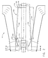
- FIG 2 is a side view of a portion of the gas turbine engine shown in Figure 1 including a support cage 100.
- Figure 3 is a perspective view of the support cage shown in Figure 2 .
- Figure 4 is an end view of the support cage shown in Figure 2 .
- support cage 100 is also referred to as a gorilla cage.
- support cage 100 is substantially frusto-conical shaped.
- frusto-conical as used herein is defined as a truncated cone or pyramid.
- support cage 100 includes a first portion 110 that is substantially circular and has a first radius 112, and a second portion 114 that is substantially circular and has a second radius 116.
- first radius 112 is larger than second radius 116.
- Support cage 100 also includes a plurality of structural members 120 that extend between, and are coupled to, first and second portions 110 and 114, respectively.
- first and second portions 110 and 114 are substantially circular.
- Each structural members 120 has a length 122 that is sized to enable support cage 100 to extend between a turbine rear frame 124 and a thrust bearing housing 126.
- each member 120 has a substantially similar length such that first portion 110 is substantially parallel to second portion 114.
- support cage 100 includes seven structural members 120 that are approximately equally spaced around a circumference of first and second portions 110 and 114, respectively. Alternatively, support cage 100 includes more or less than seven structural members.
- support cage 100 includes a first support cage structure 115 and a second support cage structure 117. More specifically, support cage 100 is fabricated in two sections 115 and 117, respectively, wherein each structure includes a plurality of members 120, such that support cage 100 can be coupled to gas turbine assembly 10.
- first support cage structure 115 is coupled to second support cage structure 117 using a welding procedure, for example.
- first support cage structure 115 is coupled to second support cage structure 117 using a plurality of mechanical fasteners.
- first support cage structure 115 extends at least 180 degrees around the power turbine centerline axis
- second support cage structure 117 extends less than 180 degrees around the power turbine centerline axis.
- first and second support cage structures 115 and 117 each extend 180 degrees around the power turbine centerline axis.
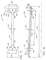
- Figure 5 is a top view of a portion of the support cage shown in Figure 2 .
- Figure 5 is a top view of a structural member 120.
- Figure 6 is a side view of the structural member shown in Figure 5 .
- Figure 7 is a side view of a portion of a connecting member 120 shown in Figures 5 and 6 .
- Each structural member 120 includes a first attachment foot 150, a second attachment foot 152, and a connecting member 154 that extends between, and is coupled to, first and second attachment feet 150 and 152, respectively.
- Connecting member 154 has a width 160, a thickness 162, and a length 164.
- First and second attachment feet 150 and 152 each include a first portion 170 and a second portion 172 that is coupled to first portion 170.
- first and second portions 170 and 172 are unitarily formed together to form unitary first and second attachment feet 150 and 152.
- Attachment feet 150 and 152 are each coupled to connecting member 154 through a brazing and/or welding procedure, for example.
- first and second attachment feet 150 and 152, and connecting member 154 are fabricated together unitarily to form each member 120.
- each member 120 is fabricated from a plurality of pieces.
- Attachment foot first portion 170 includes a first end 180 that has a width 182 that is approximately equal to connecting member width 160, and a thickness 184 that is approximately equal to connecting member thickness 162.
- Attachment foot first portion 170 includes a second end 190 that has a width 192 that is wider than first end width 182, and a thickness 194 that is narrower than first end thickness 184.
- first portion 170 has a width and thickness 182 and 184, that are approximately equal to width and thickness 160 and 162 of connecting member 120.
- first portion 170 has a width that gradually increases from first end 180 to second end 190, and a thickness that gradually decreases from first end 180 to second end 190.
- Attachment foot second portion 172 includes a first end 200 that has a width 202 that is approximately equal to first portion width 192, and a thickness 204 that is approximately equal to first portion thickness 194.
- Attachment foot second portion 172 includes a second end 210 that has a width 212 that is approximately equal to width 202 and a thickness 214 that is approximately equal to thickness 204. Accordingly, and in the exemplary embodiment, second portion 172 has a width and thickness 200 and 204, that are approximately equal between first and second ends 200 and 210, respectively.
- support cage 100 is fabricated from a material, such as, but not limited to, AISI 4140 steel which has a relatively high modulus, good ductility (LCF capability), moderate strength, and relatively low cost.
- members 120 flex in an axial direction and therefore absorb thrust loading between gas turbine engine 10 and power turbine 24.
- members 120 are fabricated from a metallic material that is different than first and second portions 110 and 114, respectively.
- support cage 100 is coupled between a power turbine thrust bearing thrust housing 126 and an interior surface 252 of power turbine 24. More specifically, first portion 110 is coupled to a power turbine frame aft internal flange 254, and second portion 114 is coupled to an external surface of thrust bearing housing 126.
- support cage 100 is coupled to gas turbine engine 10 using a plurality of mechanical fasteners such as nuts and bolts, for example.
- support cage 100 is coupled to gas turbine engine 10 using a welding and brazing procedure for example.
- support cage 100 facilitates reducing the thrust load generated by the power turbine. More specifically, support cage 100 facilitates balancing the thrust load generated by the power turbine by transferring a portion of the thrust load back to the gas turbine engine.
- gas turbine engine assembly 10 generates approximately 260,000 lbs (1157 kN). of thrust in an axially forward direction
- power turbine 24 generates approximately 240,000 Ibs (1068 kN) in an axially aft direction.
- coupling power turbine 24 to thrust bearing 54 using support cage 100 facilitates balancing the total gas turbine assembly thrust flow between gas turbine engine 10 and power turbine 24 at the engine centerline thereby reducing thrust load distortions seen by known gas turbine engines utilizing side mounted thrust supports.
- support cage 100 facilitates reducing the gas turbine engine structural distortion thereby improving blade tip clearances within the gas turbine engine.
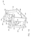
- Figure 8 is a front perspective view of an exemplary thrust bearing support assembly 300 that can be used with power turbine thrust bearing 54 shown in Figure 2 .
- Figure 9 is a rear perspective view of thrust bearing support assembly 300.
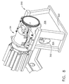
- Figure 10 is a rear perspective view of thrust bearing support assembly 300 including thrust bearing 54.
- thrust bearing support assembly 300 includes a first side 302, a second side 304, a third side 306 that is opposite first side 302, and a fourth side 308 that is opposite second side 304.
- first, second, third, and fourth sides 302, 304, 306, and 308 are fabricated from a metallic material and coupled together using a welding procedure for example and function as shear stiffener plates.
- the aft end of gorilla cage 100 and the forward end of thrust bearing 24 housing are coupled by a rabbet connection such that top portion of thrust bearing 24 can be removed for bearing service without disassembly of gorilla cage 100 or any other hardware.
- first side 302 includes an opening 310 extending therethrough that is sized to received thrust bearing 54.
- opening 310 is substantially square.
- Third side 306 includes an opening 312 extending therethrough that is sized to received thrust bearing 54.
- opening 312 is substantially semi-circular.
- Second and fourth sides 304 and 308, respectively, each include an opening 314 extending therethrough that is sized to receive an oil discharge pipe (not shown).
- openings 314 are substantially circular.
- thrust bearing assembly 300 includes two sides that are parallel to each other 302 and 306, and two sides that are not parallel to each other 304 and 308.
- Thrust bearing support assembly 300 also includes a base plate 320 that is coupled to first, second, third, and fourth sides 302, 304, 306, and 308, respectively using a welding procedure for example. Thrust bearing assembly 300 further includes a first support member 322 that is coupled to first side, second side, and fourth side 302, 304, and 308, respectively through a welding procedure for example, and a second support member 324 that hat is coupled to second side, third side, and fourth side 304, 306, and 308, respectively through a welding procedure for example. First and second support members 322 and 324 each include an alignment apparatus 326 that is coupled to each respective support member 322 and 324.
- First and second support members 322 and 324 each include an upper surface 330, a lower surface 332, and a plurality of openings 336 extending therethrough.
- support members 322 and 324 are positioned such that thrust bearing 54 can be coupled between and to support members 322 and 324. More specifically, thrust bearing 54 is coupled to support members 322 and 324 using a plurality of fasteners (not shown) that extend through plurality of openings 336.
- Each respective support member 322 and 324 includes an alignment block 338 that is configured to facilitate aligning thrust bearing 54 onto each respective support member 322 and 324.
- alignment blocks 338 also facilitate absorbing thrust that is transmitted from power turbine 24 and transfers the thrust to "ground", i.e. base plate 320.
- Thrust bearing support assembly 300 also includes a first pair of structural legs 340 and a second pair of structural legs 342 that extend between each respective support member 322 and 324 and base plate 320.
- structural legs 340 and 342 are substantially solid.
- structural legs 340 and 342 are substantially hollow.
- First pair of structural legs 340 are coupled to an axially forward end of thrust bearing support assembly 300, and second pair of structural legs 342 are coupled to an axially aft end of thrust bearing support assembly 300.
- structural legs 340 have a width 350 and structural legs 342 have a width 352 that is greater than width 342.
- coupling power turbine 24 to thrust bearing 54 using support cage 100 facilitates balancing the total gas turbine assembly thrust flow between gas turbine engine 10 and power turbine 24 thereby reducing thrust load distortions seen by the gas turbine engine.
- support cage 100 facilitates reducing the gas turbine engine structural distortion thereby improving blade tip clearances within the gas turbine engine.
- substantially all of the thrust load generated by the gas turbine engine assembly and the power turbine is reacted at the "engine centerline" axis 43 at thrust bearing 54 and transferred to ground thru pedestal structure 58. Accordingly, substantially all of the thrust generated by high pressure turbine 20, intermediate pressure turbine 22, and low pressure or power turbine 24 are reacted to ground, i.e. pedestal structure 58 utilizing support cage 100.
- thrust bearing support assembly 300 facilitates absorbing the remaining portion of thrust, or residual thrust, that is not substantially eliminated by support structure 100 by transferring the residual thrust to "ground” i.e. the support assembly 300.
- gas turbine engine assembly 10 generates approximately 260,000 lbs. of thrust in an axially forward direction
- power turbine 24 generates approximately 240,000 Ibs in an axially aft direction.
- coupling power turbine 24 to thrust bearing 54 using support cage 100 facilitates balancing substantially all of the thrust load generated by the core gas turbine engine and the power turbine between the core gas turbine engine and the power at a gas turbine engine centerline axis.
- thrust bearing support assembly 300 facilitates transferring the remaining or residual thrust load, i.e. approximately 20,000 lbs. to ground by increasing a structural stiffness of the thrust bearing support assembly. Accordingly, the thrust bearing support assembly described herein facilitates substantially eliminating the gas turbine engine structural distortion thereby improving blade tip clearances within the gas turbine engine.
- the above-described thrust bearing support assembly provides a cost-effective and device for transferring the power turbine thrust load from the power turbine thrust bearing to the thrust bearing support assembly. Accordingly, a thrust path is created between the core gas turbine engine and ground in a cost-effective manner.
- thrust bearing support assembly An exemplary embodiment of thrust bearing support assembly is described above in detail.
- the thrust bearing support assembly is not limited to the specific embodiments described herein, but rather, components of the thrust bearing support assembly may be utilized independently and separately from other components described herein.
- the thrust bearing support assembly described herein can also be used in combination with a variety of gas turbine engines.
Landscapes
- Engineering & Computer Science (AREA)
- Mechanical Engineering (AREA)
- General Engineering & Computer Science (AREA)
- Chemical & Material Sciences (AREA)
- Combustion & Propulsion (AREA)
- Turbine Rotor Nozzle Sealing (AREA)
Claims (5)
- Ensemble (10) de moteur à turbine à gaz, comportant :un générateur de gaz de turbine à gaz, comportant :un premier compresseur (14) ;un second compresseur (16) en aval dudit premier compresseur ;une turbine (20) montée en communication fluidique avec ledit second compresseur ;une turbine de travail (24) couplée audit générateur de gaz de turbine à gaz ; caractérisé par :une cage de support (100) ayant une première partie (110) qui est sensiblement circulaire et a un premier rayon (112), et une seconde partie (114) qui est sensiblement circulaire et a un second rayon (116), le premier rayon (112) étant plus grand que le second rayon (116), et les première et seconde parties (110, 114) étant réunies par une pluralité d'éléments de structure (120) de façon que la cage de support (100) ait une forme sensiblement tronconique ;un palier de butée (54) couplé à la turbine de travail (24) par l'intermédiaire de la cage de support (100) ; etun ensemble de support (300) de palier de butée supportant le palier de butée (54),le couplage de la turbine de travail (24) au palier de butée (54) par l'intermédiaire de la cage de support (100) contribuant à équilibrer sensiblement la totalité de la poussée axiale générée par le générateur de gaz de turbine à gaz et la turbine de travail entre le générateur de gaz de turbine à gaz et la turbine de travail au niveau d'un axe géométrique central de la turbine à gaz, et l'ensemble de support (300) de palier de butée contribuant à transmettre au sol le reste de la poussée axiale, qui n'est pas supprimé par la cage de support (100).
- Ensemble (10) de moteur à turbine à gaz selon la revendication 1, comprenant en outre une plaque de base (320) montée sur ledit ensemble de support (300) de palier de butée.
- Ensemble (10) de moteur à turbine à gaz selon la revendication 1, comportant en outre une paire d'éléments de support (322, 324) montés de part et d'autre dudit ensemble de support (300) de palier de butée, lesdits éléments de support étant couplés audit palier de butée (54) de turbine de travail.
- Ensemble de moteur à turbine à gaz selon la revendication 1, dans lequel la cage de support (100) est constituée de deux sections (115, 117).
- Ensemble de moteur à turbine à gaz selon la revendication 4, dans lequel la seconde section (117) s'étend sur moins de 180° autour de l'axe géométrique central de la turbine de travail (24).
Applications Claiming Priority (1)
| Application Number | Priority Date | Filing Date | Title |
|---|---|---|---|
| US11/006,924 US7546742B2 (en) | 2004-12-08 | 2004-12-08 | Gas turbine engine assembly and method of assembling same |
Publications (2)
| Publication Number | Publication Date |
|---|---|
| EP1669552A1 EP1669552A1 (fr) | 2006-06-14 |
| EP1669552B1 true EP1669552B1 (fr) | 2012-02-15 |
Family
ID=35965924
Family Applications (1)
| Application Number | Title | Priority Date | Filing Date |
|---|---|---|---|
| EP05257400A Expired - Lifetime EP1669552B1 (fr) | 2004-12-08 | 2005-12-01 | Arrangement d'une turbine à gaz |
Country Status (4)
| Country | Link |
|---|---|
| US (2) | US7546742B2 (fr) |
| EP (1) | EP1669552B1 (fr) |
| JP (1) | JP4837367B2 (fr) |
| CA (1) | CA2527651C (fr) |
Families Citing this family (33)
| Publication number | Priority date | Publication date | Assignee | Title |
|---|---|---|---|---|
| US7625128B2 (en) * | 2006-09-08 | 2009-12-01 | Pratt & Whitney Canada Corp. | Thrust bearing housing for a gas turbine engine |
| US7731426B2 (en) * | 2007-04-27 | 2010-06-08 | Honeywell International Inc. | Rotor supports and systems |
| US20110000222A1 (en) * | 2007-08-31 | 2011-01-06 | General Electric Company | Gas turbine rotor-stator support system |
| US8015820B2 (en) * | 2008-06-03 | 2011-09-13 | United Technologies Corporation | Gas turbine engine exhaust component and manufacturing method of same |
| JP5371615B2 (ja) * | 2009-08-05 | 2013-12-18 | 三菱重工業株式会社 | 軸受箱 |
| US8545681B2 (en) * | 2009-12-23 | 2013-10-01 | General Electric Company | Waste heat driven desalination process |
| DE102010044297B4 (de) * | 2010-09-03 | 2022-07-14 | Zf Friedrichshafen Ag | Drehmomentstütze |
| US9115600B2 (en) * | 2011-08-30 | 2015-08-25 | Siemens Energy, Inc. | Insulated wall section |
| US9003764B2 (en) | 2011-12-16 | 2015-04-14 | General Electric Company | System and method for thermal control in a gas turbine engine |
| US8246292B1 (en) * | 2012-01-31 | 2012-08-21 | United Technologies Corporation | Low noise turbine for geared turbofan engine |
| US20160130949A1 (en) | 2012-01-31 | 2016-05-12 | United Technologies Corporation | Low noise turbine for geared turbofan engine |
| CA2778076C (fr) * | 2012-02-27 | 2017-10-31 | Katch Kan Holdings Ltd. | Plateau pour tuyau de canalisation |
| US20160138474A1 (en) | 2012-09-28 | 2016-05-19 | United Technologies Corporation | Low noise compressor rotor for geared turbofan engine |
| US9624834B2 (en) | 2012-09-28 | 2017-04-18 | United Technologies Corporation | Low noise compressor rotor for geared turbofan engine |
| US8807492B2 (en) * | 2013-01-11 | 2014-08-19 | Western Oilfields Supply Company | Pipe crib-block |
| US11719161B2 (en) | 2013-03-14 | 2023-08-08 | Raytheon Technologies Corporation | Low noise turbine for geared gas turbine engine |
| US10605172B2 (en) | 2013-03-14 | 2020-03-31 | United Technologies Corporation | Low noise turbine for geared gas turbine engine |
| EP3011194B1 (fr) * | 2013-06-21 | 2021-08-25 | Raytheon Technologies Corporation | Rigidité de support radial de palier à roulement non linéaire |
| JP5611425B2 (ja) * | 2013-07-31 | 2014-10-22 | 三菱重工業株式会社 | 軸受箱 |
| JP5611426B2 (ja) * | 2013-07-31 | 2014-10-22 | 三菱重工業株式会社 | 軸受箱 |
| US20150184540A1 (en) * | 2013-12-31 | 2015-07-02 | Energy Recovery, Inc. | System and method for bearings |
| CA2915233C (fr) * | 2015-01-08 | 2018-12-04 | David A. Topol | Rotor de compresseur peu bruyant pour reacteur a reducteur |
| EP3286410B1 (fr) * | 2015-04-24 | 2021-06-02 | Nuovo Pignone Tecnologie Srl | Turbine à gaz ayant un boîtier comprenant des ailettes de refroidissement |
| RU2671611C1 (ru) * | 2015-07-06 | 2018-11-02 | Дрессер-Рэнд Компани | Опорная конструкция для вращающихся механизмов |
| US10221724B2 (en) | 2015-10-15 | 2019-03-05 | United Technologies Corporation | Horizontal engine build stand |
| US9777882B2 (en) * | 2015-12-03 | 2017-10-03 | Ingersoll-Rand Company | Skeleton base for a compressor system |
| US10612420B2 (en) * | 2016-11-17 | 2020-04-07 | General Electric Company | Support structures for rotors |
| US10955068B2 (en) * | 2019-01-10 | 2021-03-23 | Koenders Manufacturing 1997 Ltd | Composite pipeline sleeper with hollow outer shell and rigid internal reinforcement |
| CN109578141B (zh) * | 2019-01-23 | 2023-10-20 | 中国船舶重工集团公司第七0三研究所 | 一种可倒车燃气轮机动力涡轮的排气涡壳 |
| GB201915309D0 (en) * | 2019-10-23 | 2019-12-04 | Rolls Royce Plc | Turboshaft |
| CN115750093B (zh) | 2021-09-02 | 2025-11-07 | 通用电气公司 | 轴承支撑组件 |
| US12215630B2 (en) | 2022-12-23 | 2025-02-04 | Pratt & Whitney Canada Corp. | Flex coupler for hybrid gas turbine engine powerplant |
| US20240417092A1 (en) * | 2023-06-16 | 2024-12-19 | Pratt & Whitney Canada Corp. | System and method for controlling engines of a multi-engine aircraft engine assembly |
Family Cites Families (42)
| Publication number | Priority date | Publication date | Assignee | Title |
|---|---|---|---|---|
| US1716132A (en) * | 1926-10-30 | 1929-06-04 | Westinghouse Electric & Mfg Co | Turbine-generator support |
| US1678968A (en) * | 1927-03-01 | 1928-07-31 | Westinghouse Electric & Mfg Co | Turbine-cylinder support |
| US2535037A (en) * | 1947-05-02 | 1950-12-26 | Westinghouse Electric Corp | Turbine pedestal arrangement |
| US2568783A (en) * | 1948-03-04 | 1951-09-25 | Bauer Bros Co | Temperature controlled mill base |
| US3455107A (en) | 1967-05-25 | 1969-07-15 | Albert N Addie | Regenerative gas turbine engine structure |
| US3556672A (en) * | 1969-05-26 | 1971-01-19 | Gen Electric | Gas turbine support arrangement |
| GB1409902A (en) | 1972-05-24 | 1975-10-15 | Rolls Royce | Stationary gas turbine power plant mounting apparatus |
| US3851607A (en) * | 1973-03-29 | 1974-12-03 | Gen Electric | Regenerator support system for marine gas turbine |
| US4084861A (en) | 1976-11-11 | 1978-04-18 | United Technologies Corporation | Thrust bearing damping means |
| US4202539A (en) * | 1978-11-15 | 1980-05-13 | Avco Corporation | Engine work stand |
| EP0057294B1 (fr) | 1981-01-29 | 1985-01-30 | BBC Aktiengesellschaft Brown, Boveri & Cie. | Dispositif de support pour paliers de machines électriques |
| FR2504980B1 (fr) | 1981-04-29 | 1985-06-14 | Snecma | Montage de palier, en particulier pour turbomachines |
| IT1138763B (it) | 1981-05-04 | 1986-09-17 | Nuovo Pignone Spa | Perfezionamenti in una turbina a gas di potenza |
| IT1153351B (it) | 1982-11-23 | 1987-01-14 | Nuovo Pignone Spa | Diffusore compatto perfezionato, particolarmente adatto per turbine a gas di grande potenza |
| NL8702834A (nl) * | 1987-11-26 | 1989-06-16 | Turbo Consult Bv | Installatie voor het opwekken van mechanische energie alsmede werkwijze voor het bedrijven van een dergelijke installatie. |
| US5058373A (en) * | 1989-01-26 | 1991-10-22 | General Electric Company | Overspeed protection for a gas turbine/steam turbine combined cycle |
| US4899963A (en) * | 1989-02-06 | 1990-02-13 | Murphy Patrick J | Support saddle for elongate articles and interpositioning device for dissimilar surfaces |
| US4961310A (en) * | 1989-07-03 | 1990-10-09 | General Electric Company | Single shaft combined cycle turbine |
| JPH0687638U (ja) | 1993-05-28 | 1994-12-22 | ヤンマーディーゼル株式会社 | ガスタービン |
| US5509782A (en) * | 1995-03-02 | 1996-04-23 | Dresser-Rand Company | Bearing case support |
| US6044592A (en) * | 1996-06-27 | 2000-04-04 | Kentuckiana Curb Company | Nest of curbs |
| US6279309B1 (en) | 1998-09-24 | 2001-08-28 | Ramgen Power Systems, Inc. | Modular multi-part rail mounted engine assembly |
| US6694743B2 (en) * | 2001-07-23 | 2004-02-24 | Ramgen Power Systems, Inc. | Rotary ramjet engine with flameholder extending to running clearance at engine casing interior wall |
| US6518499B1 (en) * | 2001-08-10 | 2003-02-11 | Utility Marketing Corporation | Box pad for mounting electrical equipment |
| US6826914B2 (en) * | 2001-08-17 | 2004-12-07 | Alstom Technology Ltd | Turbogroup of a power generating plant |
| US6708500B2 (en) * | 2001-08-17 | 2004-03-23 | Alstom Technology Ltd | Turbogroup of a power generating plant |
| US20030047658A1 (en) * | 2001-08-27 | 2003-03-13 | Custom Composites, Inc. | Base pad having a leveling system and a method for manufacturing the same |
| US6889944B2 (en) * | 2001-11-15 | 2005-05-10 | Michael Brandzel | Cable to frame fastener system |
| US6708482B2 (en) | 2001-11-29 | 2004-03-23 | General Electric Company | Aircraft engine with inter-turbine engine frame |
| US6682025B2 (en) * | 2001-12-26 | 2004-01-27 | Thomas M. Turner | Pipe support |
| EP1331365A1 (fr) * | 2002-01-29 | 2003-07-30 | ABB Turbo Systems AG | Fixation d'un turbocompresseur |
| US7036318B1 (en) * | 2002-04-16 | 2006-05-02 | Altek Power Corporation | Gas turbine electric powerplant |
| US20040047526A1 (en) | 2002-09-09 | 2004-03-11 | Dewachter Ryan N. | Roller bearing with oil ring lubrication |
| US7007978B1 (en) * | 2004-05-27 | 2006-03-07 | Erik Purdom | Skate activities rail support |
| US7441731B2 (en) * | 2004-10-28 | 2008-10-28 | Smart Kenneth L | Support block system |
| US20060120854A1 (en) * | 2004-12-08 | 2006-06-08 | Wakeman Thomas G | Gas turbine engine assembly and method of assembling same |
| US7278613B2 (en) * | 2004-12-20 | 2007-10-09 | Roy David E | Pipeline skid and a skid system for use in pipeline construction |
| US7237958B2 (en) * | 2004-12-27 | 2007-07-03 | Giberson Melbourne F | Bearing stiff plate pedestal |
| US7607619B2 (en) * | 2005-08-31 | 2009-10-27 | Freedom, Inc. | Slotted conduit support block system |
| TWI289101B (en) * | 2006-03-24 | 2007-11-01 | Rexon Ind Corp Ltd | Supporting frame applied to machines and tools |
| US7731131B2 (en) * | 2008-08-15 | 2010-06-08 | Dymotek, Inc. | Roof block |
| WO2010080579A2 (fr) * | 2008-12-18 | 2010-07-15 | Erico International Corporation | Support de tuyau de toit modulaire |
-
2004
- 2004-12-08 US US11/006,924 patent/US7546742B2/en not_active Expired - Lifetime
-
2005
- 2005-11-24 JP JP2005337987A patent/JP4837367B2/ja not_active Expired - Fee Related
- 2005-11-24 CA CA2527651A patent/CA2527651C/fr not_active Expired - Fee Related
- 2005-12-01 EP EP05257400A patent/EP1669552B1/fr not_active Expired - Lifetime
-
2009
- 2009-01-23 US US12/359,066 patent/US8292238B2/en not_active Expired - Fee Related
Also Published As
| Publication number | Publication date |
|---|---|
| US8292238B2 (en) | 2012-10-23 |
| US7546742B2 (en) | 2009-06-16 |
| EP1669552A1 (fr) | 2006-06-14 |
| JP4837367B2 (ja) | 2011-12-14 |
| CA2527651A1 (fr) | 2006-06-08 |
| US20090246002A1 (en) | 2009-10-01 |
| JP2006161809A (ja) | 2006-06-22 |
| US20060117756A1 (en) | 2006-06-08 |
| CA2527651C (fr) | 2016-06-21 |
Similar Documents
| Publication | Publication Date | Title |
|---|---|---|
| EP1669552B1 (fr) | Arrangement d'une turbine à gaz | |
| EP1653045B1 (fr) | Moteur à turbine à gaz | |
| US6883303B1 (en) | Aircraft engine with inter-turbine engine frame | |
| JP4980221B2 (ja) | 軸受支持構造体、及び軸受支持構造体を有するガスタービンエンジン | |
| US8182228B2 (en) | Turbine blade having midspan shroud with recessed wear pad and methods for manufacture | |
| US6170252B1 (en) | Locator for a gearbox mount | |
| US8943840B2 (en) | Mounting assembly | |
| EP1008738A2 (fr) | Support de boitier d'engrainage avec elasticitée réglée | |
| EP3118417A1 (fr) | Ensemble de virole pour moteur de turbine à gaz | |
| EP1323983A2 (fr) | Support de chemise de chambre de combustion de turbine à gaz | |
| US6897578B1 (en) | Integrated microturbine gearbox generator assembly | |
| EP1908938A2 (fr) | Assemblage d' arbre de moteur de turbine à gaz | |
| CA2602322C (fr) | Ensemble turbine a gaz et methode de montage | |
| JP2015526626A (ja) | 高耐久性タービン排気ケース | |
| CA2762289A1 (fr) | Aube fixe avec profile composite monte sur longeron | |
| CA2527641C (fr) | Turbine a gaz et methode d'assemblage connexe | |
| JP2019082167A (ja) | ガスタービンエンジン用の回転可能なトルクフレーム | |
| US20090114766A1 (en) | Annular torsional rigid static component for an aircraft engine | |
| CN116280222A (zh) | 用于将气体涡轮引擎附接到飞行器挂架的支撑结构 | |
| EP3819478B1 (fr) | Support de palier d'arbre de transmission pour boîtier intermédiaire | |
| US8388314B2 (en) | Turbine inlet casing with integral bearing housing | |
| Rocha et al. | Evolution of the Solar Turbines Titan 130 industrial gas turbine |
Legal Events
| Date | Code | Title | Description |
|---|---|---|---|
| PUAI | Public reference made under article 153(3) epc to a published international application that has entered the european phase |
Free format text: ORIGINAL CODE: 0009012 |
|
| AK | Designated contracting states |
Kind code of ref document: A1 Designated state(s): AT BE BG CH CY CZ DE DK EE ES FI FR GB GR HU IE IS IT LI LT LU LV MC NL PL PT RO SE SI SK TR |
|
| AX | Request for extension of the european patent |
Extension state: AL BA HR MK YU |
|
| 17P | Request for examination filed |
Effective date: 20061214 |
|
| 17Q | First examination report despatched |
Effective date: 20070116 |
|
| AKX | Designation fees paid |
Designated state(s): DE FR GB IT |
|
| RAP1 | Party data changed (applicant data changed or rights of an application transferred) |
Owner name: GENERAL ELECTRIC COMPANY |
|
| GRAP | Despatch of communication of intention to grant a patent |
Free format text: ORIGINAL CODE: EPIDOSNIGR1 |
|
| GRAS | Grant fee paid |
Free format text: ORIGINAL CODE: EPIDOSNIGR3 |
|
| GRAA | (expected) grant |
Free format text: ORIGINAL CODE: 0009210 |
|
| AK | Designated contracting states |
Kind code of ref document: B1 Designated state(s): DE FR GB IT |
|
| REG | Reference to a national code |
Ref country code: GB Ref legal event code: FG4D |
|
| REG | Reference to a national code |
Ref country code: DE Ref legal event code: R082 Ref document number: 602005032675 Country of ref document: DE Representative=s name: RUEGER | ABEL PATENT- UND RECHTSANWAELTE, DE Ref country code: DE Ref legal event code: R082 Ref document number: 602005032675 Country of ref document: DE Representative=s name: RUEGER, BARTHELT & ABEL PATENTANWAELTE, DE Ref country code: DE Ref legal event code: R082 Ref document number: 602005032675 Country of ref document: DE Representative=s name: RUEGER, BARTHELT & ABEL, DE Ref country code: DE Ref legal event code: R082 Ref document number: 602005032675 Country of ref document: DE Representative=s name: RUEGER ABEL PATENT- UND RECHTSANWAELTE, DE |
|
| REG | Reference to a national code |
Ref country code: DE Ref legal event code: R096 Ref document number: 602005032675 Country of ref document: DE Effective date: 20120412 |
|
| PLBE | No opposition filed within time limit |
Free format text: ORIGINAL CODE: 0009261 |
|
| STAA | Information on the status of an ep patent application or granted ep patent |
Free format text: STATUS: NO OPPOSITION FILED WITHIN TIME LIMIT |
|
| 26N | No opposition filed |
Effective date: 20121116 |
|
| REG | Reference to a national code |
Ref country code: DE Ref legal event code: R097 Ref document number: 602005032675 Country of ref document: DE Effective date: 20121116 |
|
| REG | Reference to a national code |
Ref country code: FR Ref legal event code: PLFP Year of fee payment: 11 |
|
| REG | Reference to a national code |
Ref country code: FR Ref legal event code: PLFP Year of fee payment: 12 |
|
| PG25 | Lapsed in a contracting state [announced via postgrant information from national office to epo] |
Ref country code: IT Free format text: LAPSE BECAUSE OF NON-PAYMENT OF DUE FEES Effective date: 20151201 |
|
| PGFP | Annual fee paid to national office [announced via postgrant information from national office to epo] |
Ref country code: GB Payment date: 20161228 Year of fee payment: 12 |
|
| PGFP | Annual fee paid to national office [announced via postgrant information from national office to epo] |
Ref country code: FR Payment date: 20161227 Year of fee payment: 12 |
|
| PGFP | Annual fee paid to national office [announced via postgrant information from national office to epo] |
Ref country code: DE Payment date: 20161229 Year of fee payment: 12 |
|
| PG25 | Lapsed in a contracting state [announced via postgrant information from national office to epo] |
Ref country code: IT Free format text: LAPSE BECAUSE OF NON-PAYMENT OF DUE FEES Effective date: 20151201 |
|
| PGFP | Annual fee paid to national office [announced via postgrant information from national office to epo] |
Ref country code: IT Payment date: 20161222 Year of fee payment: 12 |
|
| PGRI | Patent reinstated in contracting state [announced from national office to epo] |
Ref country code: IT Effective date: 20170710 |
|
| REG | Reference to a national code |
Ref country code: DE Ref legal event code: R119 Ref document number: 602005032675 Country of ref document: DE |
|
| GBPC | Gb: european patent ceased through non-payment of renewal fee |
Effective date: 20171201 |
|
| REG | Reference to a national code |
Ref country code: FR Ref legal event code: ST Effective date: 20180831 |
|
| PG25 | Lapsed in a contracting state [announced via postgrant information from national office to epo] |
Ref country code: FR Free format text: LAPSE BECAUSE OF NON-PAYMENT OF DUE FEES Effective date: 20180102 Ref country code: IT Free format text: LAPSE BECAUSE OF NON-PAYMENT OF DUE FEES Effective date: 20171201 Ref country code: DE Free format text: LAPSE BECAUSE OF NON-PAYMENT OF DUE FEES Effective date: 20180703 |
|
| PG25 | Lapsed in a contracting state [announced via postgrant information from national office to epo] |
Ref country code: GB Free format text: LAPSE BECAUSE OF NON-PAYMENT OF DUE FEES Effective date: 20171201 |