EP1669227A2 - Air conditioner control device for vehicle and air conditioner control method therefor - Google Patents
Air conditioner control device for vehicle and air conditioner control method therefor Download PDFInfo
- Publication number
- EP1669227A2 EP1669227A2 EP05026489A EP05026489A EP1669227A2 EP 1669227 A2 EP1669227 A2 EP 1669227A2 EP 05026489 A EP05026489 A EP 05026489A EP 05026489 A EP05026489 A EP 05026489A EP 1669227 A2 EP1669227 A2 EP 1669227A2
- Authority
- EP
- European Patent Office
- Prior art keywords
- air conditioner
- negative pressure
- intake
- stop control
- vehicle
- Prior art date
- Legal status (The legal status is an assumption and is not a legal conclusion. Google has not performed a legal analysis and makes no representation as to the accuracy of the status listed.)
- Granted
Links
Images



Classifications
-
- B—PERFORMING OPERATIONS; TRANSPORTING
- B60—VEHICLES IN GENERAL
- B60H—ARRANGEMENTS OF HEATING, COOLING, VENTILATING OR OTHER AIR-TREATING DEVICES SPECIALLY ADAPTED FOR PASSENGER OR GOODS SPACES OF VEHICLES
- B60H1/00—Heating, cooling or ventilating devices
- B60H1/32—Cooling devices
- B60H1/3204—Cooling devices using compression
- B60H1/3205—Control means therefor
- B60H1/3208—Vehicle drive related control of the compressor drive means, e.g. for fuel saving purposes
-
- B—PERFORMING OPERATIONS; TRANSPORTING
- B60—VEHICLES IN GENERAL
- B60W—CONJOINT CONTROL OF VEHICLE SUB-UNITS OF DIFFERENT TYPE OR DIFFERENT FUNCTION; CONTROL SYSTEMS SPECIALLY ADAPTED FOR HYBRID VEHICLES; ROAD VEHICLE DRIVE CONTROL SYSTEMS FOR PURPOSES NOT RELATED TO THE CONTROL OF A PARTICULAR SUB-UNIT
- B60W10/00—Conjoint control of vehicle sub-units of different type or different function
- B60W10/04—Conjoint control of vehicle sub-units of different type or different function including control of propulsion units
- B60W10/06—Conjoint control of vehicle sub-units of different type or different function including control of propulsion units including control of combustion engines
-
- B—PERFORMING OPERATIONS; TRANSPORTING
- B60—VEHICLES IN GENERAL
- B60W—CONJOINT CONTROL OF VEHICLE SUB-UNITS OF DIFFERENT TYPE OR DIFFERENT FUNCTION; CONTROL SYSTEMS SPECIALLY ADAPTED FOR HYBRID VEHICLES; ROAD VEHICLE DRIVE CONTROL SYSTEMS FOR PURPOSES NOT RELATED TO THE CONTROL OF A PARTICULAR SUB-UNIT
- B60W10/00—Conjoint control of vehicle sub-units of different type or different function
- B60W10/30—Conjoint control of vehicle sub-units of different type or different function including control of auxiliary equipment, e.g. air-conditioning compressors or oil pumps
-
- B—PERFORMING OPERATIONS; TRANSPORTING
- B60—VEHICLES IN GENERAL
- B60W—CONJOINT CONTROL OF VEHICLE SUB-UNITS OF DIFFERENT TYPE OR DIFFERENT FUNCTION; CONTROL SYSTEMS SPECIALLY ADAPTED FOR HYBRID VEHICLES; ROAD VEHICLE DRIVE CONTROL SYSTEMS FOR PURPOSES NOT RELATED TO THE CONTROL OF A PARTICULAR SUB-UNIT
- B60W30/00—Purposes of road vehicle drive control systems not related to the control of a particular sub-unit, e.g. of systems using conjoint control of vehicle sub-units
- B60W30/18—Propelling the vehicle
- B60W30/188—Controlling power parameters of the driveline, e.g. determining the required power
- B60W30/1886—Controlling power supply to auxiliary devices
-
- B—PERFORMING OPERATIONS; TRANSPORTING
- B60—VEHICLES IN GENERAL
- B60H—ARRANGEMENTS OF HEATING, COOLING, VENTILATING OR OTHER AIR-TREATING DEVICES SPECIALLY ADAPTED FOR PASSENGER OR GOODS SPACES OF VEHICLES
- B60H1/00—Heating, cooling or ventilating devices
- B60H1/32—Cooling devices
- B60H2001/3236—Cooling devices information from a variable is obtained
- B60H2001/3266—Cooling devices information from a variable is obtained related to the operation of the vehicle
-
- B—PERFORMING OPERATIONS; TRANSPORTING
- B60—VEHICLES IN GENERAL
- B60H—ARRANGEMENTS OF HEATING, COOLING, VENTILATING OR OTHER AIR-TREATING DEVICES SPECIALLY ADAPTED FOR PASSENGER OR GOODS SPACES OF VEHICLES
- B60H1/00—Heating, cooling or ventilating devices
- B60H1/32—Cooling devices
- B60H2001/3269—Cooling devices output of a control signal
- B60H2001/327—Cooling devices output of a control signal related to a compressing unit
- B60H2001/3275—Cooling devices output of a control signal related to a compressing unit to control the volume of a compressor
-
- B—PERFORMING OPERATIONS; TRANSPORTING
- B60—VEHICLES IN GENERAL
- B60W—CONJOINT CONTROL OF VEHICLE SUB-UNITS OF DIFFERENT TYPE OR DIFFERENT FUNCTION; CONTROL SYSTEMS SPECIALLY ADAPTED FOR HYBRID VEHICLES; ROAD VEHICLE DRIVE CONTROL SYSTEMS FOR PURPOSES NOT RELATED TO THE CONTROL OF A PARTICULAR SUB-UNIT
- B60W30/00—Purposes of road vehicle drive control systems not related to the control of a particular sub-unit, e.g. of systems using conjoint control of vehicle sub-units
- B60W30/18—Propelling the vehicle
- B60W30/18009—Propelling the vehicle related to particular drive situations
- B60W30/18063—Creeping
Definitions
- the invention relates to an air conditioner control device for a vehicle, and an air conditioner control method therefor. More particularly, the invention relates to an air conditioner control device for a vehicle, which controls an air conditioner that is operated using power generated by an internal combustion engine in a vehicle including an automatically-controlled clutch provided between the internal combustion engine and a constant-mesh transmission, and a brake booster that reduces the amount of force required to depress a brake pedal, using an intake negative pressure in the internal combustion engine.
- JP-A-2003-276416 discloses an air conditioner control device in a vehicle including an air conditioner operated by an internal combustion engine, and a brake booster mechanism that reduces the amount of force required to depress a brake pedal, using an intake negative pressure in the internal combustion engine.
- the air conditioner control device for a vehicle restricts operation of the air conditioner for a predetermined time, and regulates the intake negative pressure to ensure that sufficient intake negative pressure is supplied to the brake booster mechanism when the brake is applied to decelerate the vehicle, the vehicle speed is in the range between a first preset speed and a higher second preset speed, the rate of change in the vehicle speed is equal to or greater than a preset value, and the intake negative pressure is equal to or less than a predetermined negative pressure required to operate the brake booster mechanism.
- the air conditioner control device for a vehicle restricts operation of the air conditioner only when the force supplied by the brake booster mechanism is greatly increased by restricting operation of the air conditioner at the present vehicle speed and the brake force of the vehicle is determined to be insufficient based on the present rate of change in the vehicle speed and the present intake negative pressure.
- the frequency with which operation of the air conditioner is restricted can be reduced, driveability can be improved, and occupant comfort in the vehicle compartment is maintained.
- vehicles with automatic transmissions that include a constant-mesh gear train and a clutch have been sold.
- Examples of vehicles with such an automatic transmission include vehicles in which shifting may be executed automatically, through a shift lever operated by the driver, or a combination of both shifting modes, in which the driver can select between the automatic and manual shifting modes.
- a creep control that may be referred to as "half-clutch control” is executed.
- This creep control is executed to place the clutch in the half-engaged state (so-called “half-clutch state”), and to control the rotational speed of the engine so that it remains constant when the vehicle runs at low speeds.
- the air conditioner control device for a vehicle disclosed in JP-A-2003-276416 executes the control, without regard to the sufficiency of the negative pressure in the brake booster caused by variation of the engine load. Therefore, when the engine load greatly varies, the air conditioner may be started and stopped repeatedly and frequently.
- a first aspect of the invention relates to an engine system for a vehicle, the engine system including an automatically-controlled clutch provided between an internal combustion engine and a constant-mesh transmission; and including a brake booster that reduces an amount of force required to depress a brake pedal, using an intake negative pressure in the internal combustion engine; and an air conditioner control device controlling an air conditioner that is operated using power generated by the internal combustion engine.
- the air conditioner control device includes stop control means for executing an air conditioner stop control to stop the air conditioner when a creep control is executed to place the clutch in a half-engaged state, and to control a rotational speed of the internal combustion engine so that the rotational speed remains constant.
- the stop control means may execute the air conditioner stop control to stop the air conditioner when the brake pedal of the vehicle is depressed, the speed of the vehicle is lower than a predetermined speed, and the intake negative pressure is less than a first predetermined value.
- the stop control means may terminate the air conditioner stop control when an accelerator pedal is depressed.
- the stop control means may terminate the air conditioner stop control when the intake negative pressure exceeds a second predetermined value that is greater than the first predetermined value.
- the stop control means may prevent the air conditioner from being started for a predetermined time after the air conditioner is stopped, and may prevent the air conditioner from being stopped for the predetermined time after the air conditioner is started.
- the air conditioner device may further include an intake air pressure sensor provided in an intake pipe; and the intake air pressure sensor detects the intake negative pressure.
- the air conditioner control device may further include a negative pressure sensor provided in the brake booster; and the negative pressure sensor detects the intake negative pressure.
- the air conditioner control device may further include an air flow meter provided in the intake pipe; and the intake negative pressure may be estimated based on the amount of intake air in the intake pipe that is detected by the air flow meter, the rotational speed of the internal combustion engine, and the opening amount of a throttle valve provided in the intake pipe.
- the stop control means executes the air conditioner stop control while the creep control, which may cause the load on the internal combustion engine to greatly vary, is being executed. Therefore, an increase in the load on the internal combustion engine is suppressed. Thus, it is possible to suppress the reduction of the intake negative pressure due to the increase in the intake air amount when the load on the internal combustion engine increases.
- the brake booster can reduce the amount of force required to depress the brake pedal, and the driveability of the vehicle can be improved. Also, repeated and frequent starting and stopping of the air conditioner due to the variation of the load of the internal combustion engine is avoided. Accordingly, the air conditioner can be stably operated.
- the stop control means executes the air conditioner stop control to stop the air conditioner when the brake pedal of the vehicle is depressed, the creep control is being executed, the speed of the vehicle is lower than a predetermined speed, and the intake negative pressure is less than a predetermined value.
- the driveability of the vehicle can be improved, the air conditioner can be operated stably, and the occupant can feel comfortable in the vehicle compartment using the air conditioner.
- a second aspect of the invention relates to a method for an engine system for a vehicle, the engine system including an automatically-controlled clutch provided between an internal combustion engine and a constant-mesh transmission; and a brake booster that reduces the amount of force required to depress a brake pedal, using an intake negative pressure in the internal combustion engine.
- the air conditioner control method includes the step of controlling an air conditioner that is operated using power generated by the internal combustion engine.
- the air conditioner control method further includes the step of stopping the air conditioner while a creep control is being executed to place the clutch in a half-engaged state, and to control the rotational speed of the internal combustion engine so that the rotational speed remains constant.
- the air conditioner may be stopped when the creep control is being executed to place the clutch in the half-engaged state and to control the rotational speed of the internal combustion engine so that the rotational speed remains constant, a brake pedal of the vehicle is depressed, the speed of the vehicle is lower than a predetermined speed, and the intake negative pressure is less than a predetermined value.
- FIG. 1 is a function block diagram of an engine system of a vehicle according to a first embodiment.
- an engine system 1 includes an engine 10, an automatic transmission 20, a propeller shaft 30, an intake pipe 40, a throttle valve 50, an air cleaner 60, an accelerator pedal 70, an accelerator pedal operation amount sensor 75, a brake pedal 80, a brake switch 85, a brake booster 90, a negative pressure pipe 92, a check valve 94, a compressor for an air conditioner (hereinafter, referred to as "air conditioner compressor") 100, a transmission ECU 110, and an air conditioner ECU 120.
- air conditioner compressor a compressor for an air conditioner
- the engine 10 generates power for the vehicle, and outputs the generated power to the automatic transmission 20.
- a crankshaft 12 of the engine 10 is connected to the air conditioner compressor 100 via a belt 14.
- the engine 10 outputs part of the generated power to the air conditioner compressor 100.
- the automatic transmission 20 includes a constant-mesh gear train, and a clutch (not shown).
- the clutch allows and interrupts power transmission between the engine 10 and the gear train.
- the clutch may be, for example, a dry type single plate friction clutch.
- the automatic transmission 20 selects a shift speed according to the control instruction output from the transmission ECU 110, and changes torque and a rotational speed to be transmitted from the engine 10 to the propeller shaft 30. When the vehicle stops, the automatic transmission 20 disengages the clutch to interrupt power transmission between the engine 10 and the propeller shaft 30. When the vehicle is running, the automatic transmission 20 places the clutch in the engaged state or the half engaged state (half-clutch state) to transmit power from the engine 10 to the propeller shaft 30.
- An actuator that selects the shift speed in the automatic transmission 20 may be an electric actuator or a hydraulic actuator.
- the intake pipe 40 is connected to a cylinder head (not shown) of the engine 10. Air passes through the intake pipe 40. The air is used to generate air-fuel mixture to be supplied to the engine 10.
- the throttle valve 50 is provided in the intake pipe 40. The throttle valve 50 adjusts the amount of air supplied to the engine 10 according to the position of the accelerator pedal 70.
- the air cleaner 60 is connected to the intake pipe 40. The air cleaner 60 removes foreign substances contained in the air supplied to the engine 10 through the intake pipe 40.
- the brake booster 90 is connected to the intake pipe 40 via the negative pressure pipe 92.
- the brake booster 90 reduces the amount of force required to depress the brake pedal 80, using an intake negative pressure in the intake pipe 40 that is supplied to the brake booster 90 through the negative pressure pipe 92.
- the negative pressure pipe 92 is provided to supply the intake negative pressure in the intake pipe 40 to the brake booster 90.
- the check valve 94 is provided in the negative pressure pipe 92. The check valve 94 prevents the negative pressure accumulated in the brake booster 90 from being transmitted to the intake pipe 40.
- the air conditioner compressor 100 is connected to the crank shaft 12 of the engine 10 via the belt 14.
- the air conditioner compressor 10 is operated using the power generated by the engine 10.
- the air conditioner compressor 100 is started/ stopped according to a signal EN output from the air conditioner ECU 120.
- the transmission ECU 110 selects the shift speed to be achieved by the gear train in the automatic transmission 20, and controls the engagement of the clutch.
- the transmission ECU 110 executes a creep control when the vehicle runs at low speeds. More specifically, the transmission ECU 110 executes the creep control to place the clutch of the automatic transmission 20 in the half-engaged state, and to control the rotational speed of the engine so that the rotational speed remains constant while allowing the vehicle speed to change. Then, the transmission ECU 110 outputs a signal CTL to the air conditioner ECU 120.
- the signal CTL indicates whether the creep control is being executed.
- the air conditioner ECU 120 executes a control to start or stop the air conditioner compressor 100 based on the on/off state of an air conditioner switch, the temperature in the vehicle compartment, the preset temperature of the air conditioner, and the signal CTL output from the transmission ECU 110. Then, the air conditioner ECU 120 generates the signal EN, and outputs the generated signal EN to the air conditioner compressor 100.
- the signal EN gives the instruction to start or stop the air conditioner compressor 100.
- the throttle valve 50 adjusts the amount of air supplied to the engine 10 through the intake pipe 40.
- Fuel injected from a fuel injection device (not shown) is mixed with air, and the air-fuel mixture is supplied to the engine 10. Power is generated by combustion of the air-fuel mixture.
- the engine 10 outputs the power generated to the automatic transmission 20.
- the automatic transmission 20 changes the output torque and the rotational speed transmitted from the engine 10, according to the control instruction output from the transmission ECU 110. When the vehicle runs at low speeds, the creep control is executed to place the clutch in the half-engaged state in the automatic transmission 20.
- the air conditioner compressor 100 when the air conditioner compressor 100 is instructed to start based on the signal EN output from the air conditioner ECU 120, the engine 10 outputs part of the generated power to the air conditioner compressor 100. Thus, the air conditioner compressor 100 is operated using the power from the engine 10.
- the intake negative pressure generated in the intake pipe 40 is supplied to the brake booster 90 through the negative pressure pipe 92.
- the brake booster 90 reduces the amount of force required to depress the brake pedal 80, using the intake negative pressure supplied from the negative pressure pipe 92.
- FIG. 2 is a function block diagram of the air conditioner ECU 120 shown in FIG. 1.
- the air conditioner ECU 120 includes an air conditioner stop control portion 122, and an air conditioner control portion 124.
- the air conditioner stop control portion 122 receives the signal CTL output from the transmission ECU 110.
- the signal CTL indicates whether the creep control is being executed.
- the air conditioner stop control portion 122 gives the air conditioner control portion 124 the stop instruction to stop the air conditioner.
- the air conditioner stop control portion 122 cancels the stop instruction sent to the air conditioner control portion 124.
- the air conditioner control portion 124 determines whether to start the air conditioner based on the on/off state of the air conditioner switch, the temperature in the vehicle compartment, the preset temperature of the air conditioner, and the like. Then, the air conditioner control portion 124 outputs the signal EN to the air conditioner compressor 100. The logical level of the signal EN is set according to the result of the determination. When the air conditioner stop control portion 122 gives the air conditioner control portion 124 the stop instruction to stop the air condition, the air conditioner control portion 124 stops the air conditioner compressor 100.
- the air conditioner control portion 124 executes the control to start/stop the air conditioner compressor 100 based on the on/off state of the air conditioner switch, the temperature in the vehicle compartment, the preset temperature of the air conditioner, and the like.
- the air conditioner When the creep control is executed, the air conditioner is stopped, because the clutch is placed in the half-engaged state by the creep control, and the engine load varies. In the case where the clutch load increases while the air conditioner compressor 100 that receives the power from the engine 10 is operated, the engine load increases to a large extent. In this case, the amount of the air taken into the engine 10 needs to be increased by opening the throttle valve 50, in order for the creep control to maintain a constant rotational speed of the engine 10. If the amount of the air taken into the engine 10 is increased by opening the throttle valve 50, the intake negative pressure is reduced, and sufficient negative pressure cannot be supplied to the brake booster 90. Thus, in the first embodiment, while the creep control is being executed, the air conditioner is stopped to suppress an increase in the engine load, and to obtain the negative pressure required to operate the brake booster 90.
- the air conditioner ECU 120 stops the air conditioner, which suppresses the increase in the engine load.
- the reduction of the intake negative pressure is suppressed, and the negative pressure required to operate the brake booster 90 is obtained. Accordingly, the brake booster 90 can reduce the amount of force required to depress the brake pedal, and thereby improve the driveability of the vehicle.
- the air conditioner ECU 120 stops the air conditioner while the creep control is being executed, the air conditioner is prevented from being started and stopped repeatedly and frequently due to the variation of the load of the engine 10. Accordingly, the air conditioner can be operated stably.
- the air conditioner is stopped while the creep control is being executed, irrespective of whether the negative pressure required to operate the brake booster 90 has been obtained. Therefore, in the first embodiment, the air conditioner may be unnecessarily stopped, and therefore the occupant may feel uncomfortable in the vehicle compartment. Thus, in the second embodiment, the stop instruction to stop the air conditioner is cancelled when a predetermined condition is satisfied even while the creep control is being executed.
- FIG. 3 is a function block diagram of an engine system of a vehicle according to the second embodiment of the invention.
- the configuration of an engine system 1A in the second embodiment is the same as that of the engine system 1 in the first embodiment shown in FIG. 1, except that an intake pressure sensor 52 is further provided, and an air conditioner ECU 120A is provided instead of the air conditioner ECU 120.
- the intake pressure sensor 52 detects the intake negative pressure in the intake pipe 40, and outputs an intake negative pressure signal MP to the air conditioner ECU 120A, according to the detected intake negative pressure.
- the air conditioner ECU 120A executes the control to start/stop the air conditioner compressor 100 based on the on/off state of the air conditioner switch, the temperature in the vehicle compartment, the preset temperature of the air conditioner, the signal CTL output from the transmission ECU 110, the intake negative pressure signal MP output from the intake pressure sensor 52, an accelerator pedal operation amount signal AP output from the accelerator pedal operation amount sensor 75, a brake operation signal SP output from the brake switch 85, and a vehicle speed signal detected by a vehicle speed sensor (not shown in the drawings).
- the accelerator pedal operation sensor 75 detects the operation amount of the accelerator pedal 70.
- the brake switch 85 detects whether the brake pedal 80 has been depressed. Then, the air conditioner ECU 120A generates the signal EN to give the instruction to start/stop the air conditioner compressor 100, and outputs the generated signal EN to the air conditioner compressor 100.
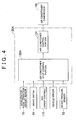
- FIG. 4 is a function block diagram of the air conditioner ECU 120A shown in FIG. 3. As shown in FIG. 4, the configuration of the air conditioner ECU 120A is the same as that of the air conditioner ECU 120 shown in FIG. 2, except that an air conditioner stop control portion 122A is provided, instead of the air conditioner stop control portion 122.
- the air conditioner stop control portion 122A determines whether to stop the air conditioner by the method described below, based on the signal CTL output from the transmission ECU 110, the intake negative pressure signal MP output from the intake pressure sensor 52, the accelerator pedal operation amount signal AP output from the accelerator pedal operation amount sensor 75, the brake operation signal SP output from the brake switch 85, and the vehicle signal output from the vehicle speed sensor.
- the air conditioner stop control portion 122A outputs the result of the determination to the air conditioner control portion 124. Also, while the air conditioner stop control portion 122A is giving the air conditioner control portion 124 the stop instruction to stop the air condition, the air conditioner stop control portion 122A determines whether to cancel the stop instruction by the method described below, and outputs the result of the determination to the air conditioner control portion 124.
- the air conditioner stop control portion 122A determines whether to stop the air conditioner using the intake negative pressure signal MP output from the intake pressure sensor 52 for the following reason. When there is sufficient intake negative pressure to operate the brake booster 90 while the air conditioner is operated, the air conditioner does not need to be stopped.
- the air conditioner stop control portion 122A determines whether to stop the air conditioner using the accelerator pedal operation amount signal AP output from the accelerator pedal operation amount sensor 75 for the following reason.
- the accelerator pedal 70 is depressed, the brake pedal 80 is not depressed, and the brake booster 90 is not operated. Therefore, the air conditioner does not need to be stopped in order to obtain the negative pressure required to operate the brake booster 90.
- the air conditioner stop control portion 122A determines whether to stop the air conditioner using the brake operation signal BS output from the brake switch 85 for the following reason.
- the brake booster 90 needs the negative pressure when the brake pedal 80 is depressed. If the brake pedal 80 is not depressed, no problem occurs even if the engine load increases due to the operation of the air conditioner, and the intake negative pressure is reduced due to the increase in the engine load.
- the air conditioner stop control portion 122A determines whether to stop the air conditioner using the vehicle speed signal output from the vehicle speed sensor for the following reason. It can be determined whether the creep control is being executed based on the vehicle speed. That is, the creep control is executed to place the clutch in the half-engaged state, and the vehicle speed at which the creep control can be executed is set for each shift speed of the automatic transmission 20. Therefore, it can be determined whether the creep control is being executed based on the vehicle speed and the selected shift speed.
- the air conditioner control portion 124 stops the air conditioner compressor 100.
- the air conditioner control portion 124 executes the control to start/stop the air conditioner compressor 100 based on the on/off state of the conditioner switch, the temperature in the vehicle compartment, the preset temperature of the air conditioner, and the like.
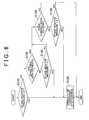
- FIG. 5 is the flowchart of the control for determining whether to perform an air conditioner stop control.
- FIG. 6 is the flowchart of the control for determining whether to terminate the air conditioner stop control.
- the air conditioner stop control is the control for stopping the air conditioner.
- the air conditioner stop control portion 122A determines whether the accelerator pedal 70 has been fully released, based on the accelerator pedal operation amount signal AP output from the accelerator pedal operation amount sensor 75 (step S10). When it is determined that the accelerator pedal 70 has not been fully released (NO in step S10), if the air conditioner stop control is being performed, the air conditioner stop control portion 122A cancels the stop instruction sent to the air conditioner control portion 124, and terminates the air conditioner stop control (step S70).
- step S10 When determining that the accelerator pedal 70 has been fully released in step S10 (YES in step S10), the air conditioner stop control portion 122A determines whether the brake pedal 80 is depressed, based on the brake operation signal SP output from the brake switch 85 (step S20). When determining that the brake pedal 80 has not been depressed (NO in step S20), the air conditioner stop control portion 122A performs an air conditioner stop control terminate control for determining whether to terminate the air conditioner stop control if the air conditioner stop control is being performed (step S80). The air conditioner stop control terminate control will be described in detail later.
- step S20 If it is determined that the brake pedal 80 is depressed in step S20 (YES in step S20), the air conditioner control portion 122A determines whether the creep control is being executed based on the signal CTL output from the transmission ECU 110 (step S30). If it is determined that the creep control is not being executed (NO in step S30), the air conditioner stop control portion 122A executes the process in step S80.
- the air conditioner stop control portion 122A reads a determination value Z from ROM (Read Only Memory), and determines whether the vehicle speed is lower than the determination value Z, based on the vehicle signal output from the vehicle speed sensor (step S40).
- the determination value Z is used to determine whether the creep control can be executed at the present vehicle speed.
- the determination value is set in advance for each shift speed.
- the air conditioner stop control portion 122A compares the vehicle speed with the determination value Z corresponding to the shift speed that is presently selected. If it is determined that the vehicle speed is equal to or higher than the determination value Z (NO in step S40), the air conditioner stop control portion 122A executes the process in step S80.
- the air conditioner stop control portion 122A reads from the ROM a determination value A concerning the intake negative pressure in the intake pipe 40, and determines whether the intake negative pressure in the intake pipe 40 is less than the determination value A, based on the intake negative pressure signal MP output from the intake pressure sensor 52 (step S50).
- step S50 If it is determined that the intake negative pressure is less than the determination value A (YES in step S50), the air conditioner stop control portion 122A determines that the negative pressure required to operate the brake booster 90 cannot be obtained. Then, the air conditioner stop control portion 122A starts the air conditioner stop control, and sends the air conditioner control portion 124 the stop instruction to stop the air conditioner (step S60). If it is determined that the intake negative pressure is equal to or greater than the determination value A (NO in step S50), the air conditioner stop control portion 122A executes the process in step S80.
- the air conditioner stop control portion 122A reads from the ROM a determination value B concerning the intake negative pressure in the intake pipe 40, and determines whether the intake negative pressure in the intake pipe 40 is greater than the determination value B, based on the intake negative pressure signal MP output from the intake pressure sensor 52 (step S110).
- the determination value B is set so that the negative pressure does not become insufficient in the brake booster 90 even if the brake pedal is intermittently depressed several times.
- step S110 If it is determined that the intake negative pressure in the intake pipe 40 is greater than the determination value B (YES in step S110), the air conditioner stop control portion 122A cancels the stop instruction sent to the air conditioner control portion 124, and terminates the air conditioner stop control (step S120).
- the air conditioner stop control portion 122A determines whether the brake pedal 80 is depressed based on the brake operation signal SP output from the brake switch 85 (step S130). If it is determined that the brake pedal 80 is depressed (NO in step S130), the air conditioner stop control portion 122A reads from the ROM a determination value C concerning the intake negative pressure in the intake pipe 40, and determines whether the intake negative pressure in the intake pipe 40 is greater than the determination value C based on the intake negative pressure signal MP output from the intake pressure sensor 52 (step S140).
- the determination value C is set so that the air conditioner stop control is terminated as soon as the brake pedal 80 is released, in order to minimize the possibility that the air conditioner stop control continues for a long period. More specifically, when the intake negative pressure in the intake pipe 40 is greater than the determination value C, it can be determined that there is sufficient intake negative pressure for the brake booster 90 to reduce the amount of force required to depress the brake pedal once next time. Also, the determination value C is set to a value less than the determination value B.
- step S140 If it is determined that the intake negative pressure in the intake pipe 40 is greater than the determination value C (YES in step S140), the air conditioner stop control portion 122A terminates the air conditioner stop control (step S120).
- step S140 determines whether the negative pressure in the intake pipe 40 is equal to or less than the determination value C in step S140 (NO in step S140). If it is determined that the negative pressure in the intake pipe 40 is equal to or less than the determination value C in step S140 (NO in step S140), the air conditioner stop control portion 122A determines whether the creep control is being executed based on the signal CTL output from the transmission ECU 110 (step S150). If it is determined that the creep control is being executed (YES in step S150), the air conditioner stop control portion 122A terminates the air conditioner stop control terminate control without terminating the air conditioner stop control.
- step S150 If it is determined that the creep control is not being executed in step S150 (NO in step S150), the air conditioner stop control portion 122A reads from the ROM a determination value D concerning the intake negative pressure in the intake pipe 40, and determines whether the intake negative pressure in the intake pipe 40 is greater than the determination value D based on the intake negative pressure signal MP output from the intake pressure sensor 52 (step S160).
- the determination value D is set so that the sufficient negative pressure can be supplied to the brake booster 90.
- the air conditioner stop control portion 122A determines that the brake pedal 80 is depressed in step S130, and determines that the creep control is not being executed in step S150, the vehicle stops in most cases. Therefore, there is no need to consider the possibility that the brake pedal is intermittently depressed several times.
- the determination value C is set to a value less than the determination value B.
- the air conditioner stop control portion 122A terminates the air conditioner stop control (step S120).
- the air conditioner stop control portion 122A terminates the air conditioner stop control terminate control without terminating the air conditioner stop control.
- each of the determination values B to D that are used in the air conditioner stop control terminate control is set to a value somewhat greater than the determination value A.
- Each of the determination values A to D may be a constant value, or may vary depending on the vehicle speed or the atmospheric pressure.
- the determination values A to D are used as criteria concerning the intake negative pressure, in order to reduce the frequency with which the air conditioner is started and stopped.
- the air conditioner may be prevented from starting for a predetermined time after the air conditioner is stopped, and the air conditioner may be prevented from stopping for the predetermined time after the air conditioner is started by a simpler method.
- the intake pressure sensor 52 detects the intake negative pressure MP in the intake pipe 40.
- a negative pressure sensor or the like may directly detect the negative pressure in the brake booster 90, and the air conditioner stop control portion 122A may base its determination on the negative pressure in the brake booster 90, instead of the intake negative pressure MP output from the intake pressure sensor 52.
- an intake air amount sensor such as an air flow meter may detect the amount of air taken into the engine through the intake pipe 40, and the intake negative pressure in the intake pipe 40 may be estimated using the detected intake air amount, the rotational speed of the engine 10, and the opening amount of the throttle valve 50.
- the air conditioner ECU 120A stops the air conditioner when the brake pedal 80 is depressed, the creep control is being executed, the vehicle speed is lower than the determination value Z, and the intake negative pressure in the intake pipe 40 is less than the determination value A.
- the increase in the engine load can be suppressed without unnecessarily stopping the air conditioner. Accordingly, the driveability of the vehicle can be improved, and the air conditioner can perform the air-conditioning function sufficiently.
- the air conditioner stop control is terminated, the determination values B to D that are different from the determination value A are used as the criteria for the intake negative pressure. Therefore, the air conditioner is prevented from being started and stopped repeatedly and frequently. Thus, the air conditioner is operated stably.
- the air conditioner ECUs 120 and 120A correspond to "the air conditioner control device for a vehicle” and “the air conditioner control device”.
- the air conditioner stop control portions 122 and 122A correspond to "the stop control means”.
- the transmission ECU 110 corresponds to "the clutch control device”.
Landscapes
- Engineering & Computer Science (AREA)
- Chemical & Material Sciences (AREA)
- Combustion & Propulsion (AREA)
- Mechanical Engineering (AREA)
- Transportation (AREA)
- Physics & Mathematics (AREA)
- Thermal Sciences (AREA)
- Automation & Control Theory (AREA)
- Air-Conditioning For Vehicles (AREA)
- Control Of Vehicle Engines Or Engines For Specific Uses (AREA)
Abstract
Description
- The invention relates to an air conditioner control device for a vehicle, and an air conditioner control method therefor. More particularly, the invention relates to an air conditioner control device for a vehicle, which controls an air conditioner that is operated using power generated by an internal combustion engine in a vehicle including an automatically-controlled clutch provided between the internal combustion engine and a constant-mesh transmission, and a brake booster that reduces the amount of force required to depress a brake pedal, using an intake negative pressure in the internal combustion engine.
- Japanese Patent Application Publication No. JP-A-2003-276416 (hereinafter, referred to as "JP-A-2003-276416) discloses an air conditioner control device in a vehicle including an air conditioner operated by an internal combustion engine, and a brake booster mechanism that reduces the amount of force required to depress a brake pedal, using an intake negative pressure in the internal combustion engine.
- The air conditioner control device for a vehicle restricts operation of the air conditioner for a predetermined time, and regulates the intake negative pressure to ensure that sufficient intake negative pressure is supplied to the brake booster mechanism when the brake is applied to decelerate the vehicle, the vehicle speed is in the range between a first preset speed and a higher second preset speed, the rate of change in the vehicle speed is equal to or greater than a preset value, and the intake negative pressure is equal to or less than a predetermined negative pressure required to operate the brake booster mechanism.
- The air conditioner control device for a vehicle restricts operation of the air conditioner only when the force supplied by the brake booster mechanism is greatly increased by restricting operation of the air conditioner at the present vehicle speed and the brake force of the vehicle is determined to be insufficient based on the present rate of change in the vehicle speed and the present intake negative pressure. Thus, the frequency with which operation of the air conditioner is restricted can be reduced, driveability can be improved, and occupant comfort in the vehicle compartment is maintained.
- Recently, particularly in Europe, vehicles with automatic transmissions that include a constant-mesh gear train and a clutch have been sold. Examples of vehicles with such an automatic transmission include vehicles in which shifting may be executed automatically, through a shift lever operated by the driver, or a combination of both shifting modes, in which the driver can select between the automatic and manual shifting modes.
- In vehicles equipped with such an automatic transmission, a creep control (that may be referred to as "half-clutch control") is executed. This creep control is executed to place the clutch in the half-engaged state (so-called "half-clutch state"), and to control the rotational speed of the engine so that it remains constant when the vehicle runs at low speeds.
- While this creep control is being executed, the slippage of the clutch changes depending on the temperature or the like of the clutch, and the engine load greatly varies. When the engine load is increased, and the execution of the creep control and the operation of auxiliary devices, such as an air conditioner, further increase the load, the creep control will need to increase the amount of air taken into the engine by opening the throttle valve so that the engine rotational speed can be kept constant.
- This reduces the intake negative pressure in the intake pipe, which causes the negative pressure in the brake booster to become insufficient to reduce the amount of force required to depress the brake pedal using the intake negative pressure. As a result, the assist provided by the brake booster is significantly reduced, which increases the amount of force required to depress the brake pedal, and therefore driveability of the vehicle deteriorates. (In the preceding paragraphs and throughout the rest of the specification, the term "negative pressure" signifies the difference between the atmospheric pressure and the pressure in the intake pipe or the brake booster. When the pressure in the intake pipe or the brake booster is less than the atmospheric pressure, the value of the negative pressure is a positive value).
- The air conditioner control device for a vehicle disclosed in JP-A-2003-276416 executes the control, without regard to the sufficiency of the negative pressure in the brake booster caused by variation of the engine load. Therefore, when the engine load greatly varies, the air conditioner may be started and stopped repeatedly and frequently.
- It is an object of the invention to provide an air conditioner control device for a vehicle and an air conditioner control method for a vehicle that improves the driveability of a vehicle and allows the air conditioner to be operated stably using rotational force of an internal combustion engine.
- A first aspect of the invention relates to an engine system for a vehicle, the engine system including an automatically-controlled clutch provided between an internal combustion engine and a constant-mesh transmission; and including a brake booster that reduces an amount of force required to depress a brake pedal, using an intake negative pressure in the internal combustion engine; and an air conditioner control device controlling an air conditioner that is operated using power generated by the internal combustion engine. The air conditioner control device includes stop control means for executing an air conditioner stop control to stop the air conditioner when a creep control is executed to place the clutch in a half-engaged state, and to control a rotational speed of the internal combustion engine so that the rotational speed remains constant.
- According to an embodiment of the invention, the stop control means may execute the air conditioner stop control to stop the air conditioner when the brake pedal of the vehicle is depressed, the speed of the vehicle is lower than a predetermined speed, and the intake negative pressure is less than a first predetermined value.
- The stop control means may terminate the air conditioner stop control when an accelerator pedal is depressed.
- The stop control means may terminate the air conditioner stop control when the intake negative pressure exceeds a second predetermined value that is greater than the first predetermined value.
- The stop control means may prevent the air conditioner from being started for a predetermined time after the air conditioner is stopped, and may prevent the air conditioner from being stopped for the predetermined time after the air conditioner is started.
- The air conditioner device may further include an intake air pressure sensor provided in an intake pipe; and the intake air pressure sensor detects the intake negative pressure.
- The air conditioner control device may further include a negative pressure sensor provided in the brake booster; and the negative pressure sensor detects the intake negative pressure.
- The air conditioner control device may further include an air flow meter provided in the intake pipe; and the intake negative pressure may be estimated based on the amount of intake air in the intake pipe that is detected by the air flow meter, the rotational speed of the internal combustion engine, and the opening amount of a throttle valve provided in the intake pipe.
- In the engine system for the vehicle according to the first aspect of the invention, the stop control means executes the air conditioner stop control while the creep control, which may cause the load on the internal combustion engine to greatly vary, is being executed. Therefore, an increase in the load on the internal combustion engine is suppressed. Thus, it is possible to suppress the reduction of the intake negative pressure due to the increase in the intake air amount when the load on the internal combustion engine increases.
- Thus, according to the first aspect of the invention, the brake booster can reduce the amount of force required to depress the brake pedal, and the driveability of the vehicle can be improved. Also, repeated and frequent starting and stopping of the air conditioner due to the variation of the load of the internal combustion engine is avoided. Accordingly, the air conditioner can be stably operated.
- In the air conditioner control device for a vehicle according to the first aspect of the invention, the stop control means executes the air conditioner stop control to stop the air conditioner when the brake pedal of the vehicle is depressed, the creep control is being executed, the speed of the vehicle is lower than a predetermined speed, and the intake negative pressure is less than a predetermined value. Thus, it is possible to avoid unnecessarily stopping the air conditioner, while suppressing an increase in the load on the internal combustion engine.
- Thus, according to the first aspect of the invention, the driveability of the vehicle can be improved, the air conditioner can be operated stably, and the occupant can feel comfortable in the vehicle compartment using the air conditioner.
- A second aspect of the invention relates to a method for an engine system for a vehicle, the engine system including an automatically-controlled clutch provided between an internal combustion engine and a constant-mesh transmission; and a brake booster that reduces the amount of force required to depress a brake pedal, using an intake negative pressure in the internal combustion engine. The air conditioner control method includes the step of controlling an air conditioner that is operated using power generated by the internal combustion engine. The air conditioner control method further includes the step of stopping the air conditioner while a creep control is being executed to place the clutch in a half-engaged state, and to control the rotational speed of the internal combustion engine so that the rotational speed remains constant.
- The air conditioner may be stopped when the creep control is being executed to place the clutch in the half-engaged state and to control the rotational speed of the internal combustion engine so that the rotational speed remains constant, a brake pedal of the vehicle is depressed, the speed of the vehicle is lower than a predetermined speed, and the intake negative pressure is less than a predetermined value.
- The foregoing and further objects, features and advantages of the invention will become apparent from the following description of exemplary embodiments with reference to the accompanying drawings, wherein like numerals are used to represent like elements and wherein:
- FIG. 1 is a function block diagram of an engine system of a vehicle in a first embodiment of the invention;
- FIG. 2 is a function block diagram of an air conditioner ECU shown in FIG. 1;
- FIG. 3 is a function block diagram of an engine system of a vehicle in a second embodiment of the invention;
- FIG. 4 is a function block diagram of an air conditioner ECU shown in FIG. 3;
- FIG. 5 is a first flowchart of a control executed by an air conditioner stop control portion shown in FIG. 4; and
- FIG. 6 is a second flowchart of the control executed by the air conditioner stop control portion shown in FIG. 4.
- Hereinafter, example embodiments of the invention will be described in detail with reference to the drawings. In the drawings, the same or corresponding portions are denoted by the same reference numerals, and redundant description thereof will be omitted.
- FIG. 1 is a function block diagram of an engine system of a vehicle according to a first embodiment. As shown in FIG. 1, an
engine system 1 includes anengine 10, anautomatic transmission 20, apropeller shaft 30, anintake pipe 40, athrottle valve 50, anair cleaner 60, anaccelerator pedal 70, an accelerator pedaloperation amount sensor 75, abrake pedal 80, abrake switch 85, abrake booster 90, anegative pressure pipe 92, acheck valve 94, a compressor for an air conditioner (hereinafter, referred to as "air conditioner compressor") 100, atransmission ECU 110, and an air conditioner ECU 120. - The
engine 10 generates power for the vehicle, and outputs the generated power to theautomatic transmission 20. Acrankshaft 12 of theengine 10 is connected to theair conditioner compressor 100 via abelt 14. Theengine 10 outputs part of the generated power to theair conditioner compressor 100. - The
automatic transmission 20 includes a constant-mesh gear train, and a clutch (not shown). The clutch allows and interrupts power transmission between theengine 10 and the gear train. The clutch may be, for example, a dry type single plate friction clutch. Theautomatic transmission 20 selects a shift speed according to the control instruction output from thetransmission ECU 110, and changes torque and a rotational speed to be transmitted from theengine 10 to thepropeller shaft 30. When the vehicle stops, theautomatic transmission 20 disengages the clutch to interrupt power transmission between theengine 10 and thepropeller shaft 30. When the vehicle is running, theautomatic transmission 20 places the clutch in the engaged state or the half engaged state (half-clutch state) to transmit power from theengine 10 to thepropeller shaft 30. An actuator that selects the shift speed in theautomatic transmission 20 may be an electric actuator or a hydraulic actuator. - The
intake pipe 40 is connected to a cylinder head (not shown) of theengine 10. Air passes through theintake pipe 40. The air is used to generate air-fuel mixture to be supplied to theengine 10. Thethrottle valve 50 is provided in theintake pipe 40. Thethrottle valve 50 adjusts the amount of air supplied to theengine 10 according to the position of theaccelerator pedal 70. Theair cleaner 60 is connected to theintake pipe 40. Theair cleaner 60 removes foreign substances contained in the air supplied to theengine 10 through theintake pipe 40. - The
brake booster 90 is connected to theintake pipe 40 via thenegative pressure pipe 92. Thebrake booster 90 reduces the amount of force required to depress thebrake pedal 80, using an intake negative pressure in theintake pipe 40 that is supplied to thebrake booster 90 through thenegative pressure pipe 92. Thenegative pressure pipe 92 is provided to supply the intake negative pressure in theintake pipe 40 to thebrake booster 90. Thecheck valve 94 is provided in thenegative pressure pipe 92. Thecheck valve 94 prevents the negative pressure accumulated in thebrake booster 90 from being transmitted to theintake pipe 40. - The
air conditioner compressor 100 is connected to thecrank shaft 12 of theengine 10 via thebelt 14. Theair conditioner compressor 10 is operated using the power generated by theengine 10. Theair conditioner compressor 100 is started/ stopped according to a signal EN output from theair conditioner ECU 120. - The
transmission ECU 110 selects the shift speed to be achieved by the gear train in theautomatic transmission 20, and controls the engagement of the clutch. Thetransmission ECU 110 executes a creep control when the vehicle runs at low speeds. More specifically, thetransmission ECU 110 executes the creep control to place the clutch of theautomatic transmission 20 in the half-engaged state, and to control the rotational speed of the engine so that the rotational speed remains constant while allowing the vehicle speed to change. Then, thetransmission ECU 110 outputs a signal CTL to theair conditioner ECU 120. The signal CTL indicates whether the creep control is being executed. - The
air conditioner ECU 120 executes a control to start or stop theair conditioner compressor 100 based on the on/off state of an air conditioner switch, the temperature in the vehicle compartment, the preset temperature of the air conditioner, and the signal CTL output from thetransmission ECU 110. Then, theair conditioner ECU 120 generates the signal EN, and outputs the generated signal EN to theair conditioner compressor 100. The signal EN gives the instruction to start or stop theair conditioner compressor 100. - In this
engine system 1, thethrottle valve 50 adjusts the amount of air supplied to theengine 10 through theintake pipe 40. Fuel injected from a fuel injection device (not shown) is mixed with air, and the air-fuel mixture is supplied to theengine 10. Power is generated by combustion of the air-fuel mixture. Theengine 10 outputs the power generated to theautomatic transmission 20. Theautomatic transmission 20 changes the output torque and the rotational speed transmitted from theengine 10, according to the control instruction output from thetransmission ECU 110. When the vehicle runs at low speeds, the creep control is executed to place the clutch in the half-engaged state in theautomatic transmission 20. - Also, when the
air conditioner compressor 100 is instructed to start based on the signal EN output from theair conditioner ECU 120, theengine 10 outputs part of the generated power to theair conditioner compressor 100. Thus, theair conditioner compressor 100 is operated using the power from theengine 10. - Further, in the
engine system 1, the intake negative pressure generated in theintake pipe 40 is supplied to thebrake booster 90 through thenegative pressure pipe 92. Thebrake booster 90 reduces the amount of force required to depress thebrake pedal 80, using the intake negative pressure supplied from thenegative pressure pipe 92. - FIG. 2 is a function block diagram of the
air conditioner ECU 120 shown in FIG. 1. As shown in FIG. 2, theair conditioner ECU 120 includes an air conditionerstop control portion 122, and an airconditioner control portion 124. The air conditionerstop control portion 122 receives the signal CTL output from thetransmission ECU 110. The signal CTL indicates whether the creep control is being executed. When the level (logical level) of the signal CTL is high, that is, when the creep control is being executed, the air conditionerstop control portion 122 gives the airconditioner control portion 124 the stop instruction to stop the air conditioner. When the level (logical level) of the signal CTL is low, that is, when the creep control is not being executed, the air conditionerstop control portion 122 cancels the stop instruction sent to the airconditioner control portion 124. - The air
conditioner control portion 124 determines whether to start the air conditioner based on the on/off state of the air conditioner switch, the temperature in the vehicle compartment, the preset temperature of the air conditioner, and the like. Then, the airconditioner control portion 124 outputs the signal EN to theair conditioner compressor 100. The logical level of the signal EN is set according to the result of the determination. When the air conditionerstop control portion 122 gives the airconditioner control portion 124 the stop instruction to stop the air condition, the airconditioner control portion 124 stops theair conditioner compressor 100. When the air conditionerstop control portion 122 does not give the airconditioner control portion 124 the stop instruction to stop the air conditioner, the airconditioner control portion 124 executes the control to start/stop theair conditioner compressor 100 based on the on/off state of the air conditioner switch, the temperature in the vehicle compartment, the preset temperature of the air conditioner, and the like. - When the creep control is executed, the air conditioner is stopped, because the clutch is placed in the half-engaged state by the creep control, and the engine load varies. In the case where the clutch load increases while the
air conditioner compressor 100 that receives the power from theengine 10 is operated, the engine load increases to a large extent. In this case, the amount of the air taken into theengine 10 needs to be increased by opening thethrottle valve 50, in order for the creep control to maintain a constant rotational speed of theengine 10. If the amount of the air taken into theengine 10 is increased by opening thethrottle valve 50, the intake negative pressure is reduced, and sufficient negative pressure cannot be supplied to thebrake booster 90. Thus, in the first embodiment, while the creep control is being executed, the air conditioner is stopped to suppress an increase in the engine load, and to obtain the negative pressure required to operate thebrake booster 90. - Thus, in the first embodiment, while the creep control is being executed, the
air conditioner ECU 120 stops the air conditioner, which suppresses the increase in the engine load. As a result, the reduction of the intake negative pressure is suppressed, and the negative pressure required to operate thebrake booster 90 is obtained. Accordingly, thebrake booster 90 can reduce the amount of force required to depress the brake pedal, and thereby improve the driveability of the vehicle. - When the creep control is executed, the load of the
engine 10 varies due to the variation of the clutch load. However, because theair conditioner ECU 120 stops the air conditioner while the creep control is being executed, the air conditioner is prevented from being started and stopped repeatedly and frequently due to the variation of the load of theengine 10. Accordingly, the air conditioner can be operated stably. - In the first embodiment, the air conditioner is stopped while the creep control is being executed, irrespective of whether the negative pressure required to operate the
brake booster 90 has been obtained. Therefore, in the first embodiment, the air conditioner may be unnecessarily stopped, and therefore the occupant may feel uncomfortable in the vehicle compartment. Thus, in the second embodiment, the stop instruction to stop the air conditioner is cancelled when a predetermined condition is satisfied even while the creep control is being executed. - FIG. 3 is a function block diagram of an engine system of a vehicle according to the second embodiment of the invention. As shown in FIG. 3, the configuration of an
engine system 1A in the second embodiment is the same as that of theengine system 1 in the first embodiment shown in FIG. 1, except that anintake pressure sensor 52 is further provided, and anair conditioner ECU 120A is provided instead of theair conditioner ECU 120. Theintake pressure sensor 52 detects the intake negative pressure in theintake pipe 40, and outputs an intake negative pressure signal MP to theair conditioner ECU 120A, according to the detected intake negative pressure. - The
air conditioner ECU 120A executes the control to start/stop theair conditioner compressor 100 based on the on/off state of the air conditioner switch, the temperature in the vehicle compartment, the preset temperature of the air conditioner, the signal CTL output from thetransmission ECU 110, the intake negative pressure signal MP output from theintake pressure sensor 52, an accelerator pedal operation amount signal AP output from the accelerator pedaloperation amount sensor 75, a brake operation signal SP output from thebrake switch 85, and a vehicle speed signal detected by a vehicle speed sensor (not shown in the drawings). The acceleratorpedal operation sensor 75 detects the operation amount of theaccelerator pedal 70. Thebrake switch 85 detects whether thebrake pedal 80 has been depressed. Then, theair conditioner ECU 120A generates the signal EN to give the instruction to start/stop theair conditioner compressor 100, and outputs the generated signal EN to theair conditioner compressor 100. - Other portions of the configuration of the
engine system 1A are the same as those of theengine system 1 in the first embodiment shown in FIG. 1. - FIG. 4 is a function block diagram of the
air conditioner ECU 120A shown in FIG. 3. As shown in FIG. 4, the configuration of theair conditioner ECU 120A is the same as that of theair conditioner ECU 120 shown in FIG. 2, except that an air conditionerstop control portion 122A is provided, instead of the air conditionerstop control portion 122. - The air conditioner
stop control portion 122A determines whether to stop the air conditioner by the method described below, based on the signal CTL output from thetransmission ECU 110, the intake negative pressure signal MP output from theintake pressure sensor 52, the accelerator pedal operation amount signal AP output from the accelerator pedaloperation amount sensor 75, the brake operation signal SP output from thebrake switch 85, and the vehicle signal output from the vehicle speed sensor. The air conditionerstop control portion 122A outputs the result of the determination to the airconditioner control portion 124. Also, while the air conditionerstop control portion 122A is giving the airconditioner control portion 124 the stop instruction to stop the air condition, the air conditionerstop control portion 122A determines whether to cancel the stop instruction by the method described below, and outputs the result of the determination to the airconditioner control portion 124. - The air conditioner
stop control portion 122A determines whether to stop the air conditioner using the intake negative pressure signal MP output from theintake pressure sensor 52 for the following reason. When there is sufficient intake negative pressure to operate thebrake booster 90 while the air conditioner is operated, the air conditioner does not need to be stopped. - The air conditioner
stop control portion 122A determines whether to stop the air conditioner using the accelerator pedal operation amount signal AP output from the accelerator pedaloperation amount sensor 75 for the following reason. When theaccelerator pedal 70 is depressed, thebrake pedal 80 is not depressed, and thebrake booster 90 is not operated. Therefore, the air conditioner does not need to be stopped in order to obtain the negative pressure required to operate thebrake booster 90. - Also, the air conditioner
stop control portion 122A determines whether to stop the air conditioner using the brake operation signal BS output from thebrake switch 85 for the following reason. Thebrake booster 90 needs the negative pressure when thebrake pedal 80 is depressed. If thebrake pedal 80 is not depressed, no problem occurs even if the engine load increases due to the operation of the air conditioner, and the intake negative pressure is reduced due to the increase in the engine load. - The air conditioner
stop control portion 122A determines whether to stop the air conditioner using the vehicle speed signal output from the vehicle speed sensor for the following reason. It can be determined whether the creep control is being executed based on the vehicle speed. That is, the creep control is executed to place the clutch in the half-engaged state, and the vehicle speed at which the creep control can be executed is set for each shift speed of theautomatic transmission 20. Therefore, it can be determined whether the creep control is being executed based on the vehicle speed and the selected shift speed. - When the air conditioner
stop control portion 122A gives the airconditioner control portion 124 the instruction to stop the air conditioner, the airconditioner control portion 124 stops theair conditioner compressor 100. When the air conditionerstop control portion 122A cancels the stop instruction, the airconditioner control portion 124 executes the control to start/stop theair conditioner compressor 100 based on the on/off state of the conditioner switch, the temperature in the vehicle compartment, the preset temperature of the air conditioner, and the like. - Each of FIG. 5 and FIG. 6 shows the flowchart of the control performed by the air conditioner
stop control portion 122A shown in FIG. 4. FIG. 5 is the flowchart of the control for determining whether to perform an air conditioner stop control. FIG. 6 is the flowchart of the control for determining whether to terminate the air conditioner stop control. The air conditioner stop control is the control for stopping the air conditioner. - As shown in FIG. 5, the air conditioner
stop control portion 122A determines whether theaccelerator pedal 70 has been fully released, based on the accelerator pedal operation amount signal AP output from the accelerator pedal operation amount sensor 75 (step S10). When it is determined that theaccelerator pedal 70 has not been fully released (NO in step S10), if the air conditioner stop control is being performed, the air conditionerstop control portion 122A cancels the stop instruction sent to the airconditioner control portion 124, and terminates the air conditioner stop control (step S70). - When determining that the
accelerator pedal 70 has been fully released in step S10 (YES in step S10), the air conditionerstop control portion 122A determines whether thebrake pedal 80 is depressed, based on the brake operation signal SP output from the brake switch 85 (step S20). When determining that thebrake pedal 80 has not been depressed (NO in step S20), the air conditionerstop control portion 122A performs an air conditioner stop control terminate control for determining whether to terminate the air conditioner stop control if the air conditioner stop control is being performed (step S80). The air conditioner stop control terminate control will be described in detail later. - If it is determined that the
brake pedal 80 is depressed in step S20 (YES in step S20), the airconditioner control portion 122A determines whether the creep control is being executed based on the signal CTL output from the transmission ECU 110 (step S30). If it is determined that the creep control is not being executed (NO in step S30), the air conditionerstop control portion 122A executes the process in step S80. - If it is determined that the creep control is being executed in step S30 (YES in step S30), the air conditioner
stop control portion 122A reads a determination value Z from ROM (Read Only Memory), and determines whether the vehicle speed is lower than the determination value Z, based on the vehicle signal output from the vehicle speed sensor (step S40). The determination value Z is used to determine whether the creep control can be executed at the present vehicle speed. The determination value .is set in advance for each shift speed. The air conditionerstop control portion 122A compares the vehicle speed with the determination value Z corresponding to the shift speed that is presently selected. If it is determined that the vehicle speed is equal to or higher than the determination value Z (NO in step S40), the air conditionerstop control portion 122A executes the process in step S80. - If it is determined that the vehicle speed is lower than the determination value Z in step S40 (YES in step S40), the air conditioner
stop control portion 122A reads from the ROM a determination value A concerning the intake negative pressure in theintake pipe 40, and determines whether the intake negative pressure in theintake pipe 40 is less than the determination value A, based on the intake negative pressure signal MP output from the intake pressure sensor 52 (step S50). - If it is determined that the intake negative pressure is less than the determination value A (YES in step S50), the air conditioner
stop control portion 122A determines that the negative pressure required to operate thebrake booster 90 cannot be obtained. Then, the air conditionerstop control portion 122A starts the air conditioner stop control, and sends the airconditioner control portion 124 the stop instruction to stop the air conditioner (step S60). If it is determined that the intake negative pressure is equal to or greater than the determination value A (NO in step S50), the air conditionerstop control portion 122A executes the process in step S80. - Next, the processes of the air conditioner stop control terminate control in step S80 in FIG. 5 will be described.
- As shown in FIG. 6, the air conditioner
stop control portion 122A reads from the ROM a determination value B concerning the intake negative pressure in theintake pipe 40, and determines whether the intake negative pressure in theintake pipe 40 is greater than the determination value B, based on the intake negative pressure signal MP output from the intake pressure sensor 52 (step S110). For example, the determination value B is set so that the negative pressure does not become insufficient in thebrake booster 90 even if the brake pedal is intermittently depressed several times. Thus, the air conditioner stop control is prevented from being started and terminated repeatedly, and the air conditioner is prevented from being started and stopped repeatedly and frequently when the brake pedal is intermittently depressed several times. - If it is determined that the intake negative pressure in the
intake pipe 40 is greater than the determination value B (YES in step S110), the air conditionerstop control portion 122A cancels the stop instruction sent to the airconditioner control portion 124, and terminates the air conditioner stop control (step S120). - If it is determined that the intake negative pressure in the
intake pipe 40 is equal to or less than the determination value B (NO in step S110), the air conditionerstop control portion 122A determines whether thebrake pedal 80 is depressed based on the brake operation signal SP output from the brake switch 85 (step S130). If it is determined that thebrake pedal 80 is depressed (NO in step S130), the air conditionerstop control portion 122A reads from the ROM a determination value C concerning the intake negative pressure in theintake pipe 40, and determines whether the intake negative pressure in theintake pipe 40 is greater than the determination value C based on the intake negative pressure signal MP output from the intake pressure sensor 52 (step S140). - The determination value C is set so that the air conditioner stop control is terminated as soon as the
brake pedal 80 is released, in order to minimize the possibility that the air conditioner stop control continues for a long period. More specifically, when the intake negative pressure in theintake pipe 40 is greater than the determination value C, it can be determined that there is sufficient intake negative pressure for thebrake booster 90 to reduce the amount of force required to depress the brake pedal once next time. Also, the determination value C is set to a value less than the determination value B. - If it is determined that the intake negative pressure in the
intake pipe 40 is greater than the determination value C (YES in step S140), the air conditionerstop control portion 122A terminates the air conditioner stop control (step S120). - If it is determined that the negative pressure in the
intake pipe 40 is equal to or less than the determination value C in step S140 (NO in step S140), the air conditionerstop control portion 122A determines whether the creep control is being executed based on the signal CTL output from the transmission ECU 110 (step S150). If it is determined that the creep control is being executed (YES in step S150), the air conditionerstop control portion 122A terminates the air conditioner stop control terminate control without terminating the air conditioner stop control. - If it is determined that the creep control is not being executed in step S150 (NO in step S150), the air conditioner
stop control portion 122A reads from the ROM a determination value D concerning the intake negative pressure in theintake pipe 40, and determines whether the intake negative pressure in theintake pipe 40 is greater than the determination value D based on the intake negative pressure signal MP output from the intake pressure sensor 52 (step S160). - The determination value D is set so that the sufficient negative pressure can be supplied to the
brake booster 90. When the air conditionerstop control portion 122A determines that thebrake pedal 80 is depressed in step S130, and determines that the creep control is not being executed in step S150, the vehicle stops in most cases. Therefore, there is no need to consider the possibility that the brake pedal is intermittently depressed several times. Thus, the determination value C is set to a value less than the determination value B. - When determining that the intake negative pressure in the
intake pipe 40 is greater than the determination value D in step S160 (YES in step S160), the air conditionerstop control portion 122A terminates the air conditioner stop control (step S120). When determining that the intake negative pressure in theintake pipe 40 is equal to or less than the determination value D in step S160 (NO in step S160), the air conditionerstop control portion 122A terminates the air conditioner stop control terminate control without terminating the air conditioner stop control. - In order to prevent the air conditioner stop control from being started and stopped repeatedly and frequently when the intake negative pressure is near the determination value A that is used to determine whether to start the air conditioner stop control, each of the determination values B to D that are used in the air conditioner stop control terminate control is set to a value somewhat greater than the determination value A.
- Each of the determination values A to D may be a constant value, or may vary depending on the vehicle speed or the atmospheric pressure.
- In the aforementioned embodiment, the determination values A to D are used as criteria concerning the intake negative pressure, in order to reduce the frequency with which the air conditioner is started and stopped. However, the air conditioner may be prevented from starting for a predetermined time after the air conditioner is stopped, and the air conditioner may be prevented from stopping for the predetermined time after the air conditioner is started by a simpler method.
- In the aforementioned embodiment, the
intake pressure sensor 52 detects the intake negative pressure MP in theintake pipe 40. However, a negative pressure sensor or the like may directly detect the negative pressure in thebrake booster 90, and the air conditionerstop control portion 122A may base its determination on the negative pressure in thebrake booster 90, instead of the intake negative pressure MP output from theintake pressure sensor 52. Alternatively, an intake air amount sensor such as an air flow meter may detect the amount of air taken into the engine through theintake pipe 40, and the intake negative pressure in theintake pipe 40 may be estimated using the detected intake air amount, the rotational speed of theengine 10, and the opening amount of thethrottle valve 50. - As described above, in the second embodiment, the
air conditioner ECU 120A stops the air conditioner when thebrake pedal 80 is depressed, the creep control is being executed, the vehicle speed is lower than the determination value Z, and the intake negative pressure in theintake pipe 40 is less than the determination value A. Thus, the increase in the engine load can be suppressed without unnecessarily stopping the air conditioner. Accordingly, the driveability of the vehicle can be improved, and the air conditioner can perform the air-conditioning function sufficiently. - Also, when the air conditioner stop control is terminated, the determination values B to D that are different from the determination value A are used as the criteria for the intake negative pressure. Therefore, the air conditioner is prevented from being started and stopped repeatedly and frequently. Thus, the air conditioner is operated stably.
- In the aforementioned embodiments, the
air conditioner ECUs stop control portions transmission ECU 110 corresponds to "the clutch control device". - Thus, the embodiments of the invention disclosed in the specification are illustrative. It should be understood and appreciated that one skilled in the art would understand that the invention should not be restricted to the particulars of the embodiments described. The technical scope of the invention is defined by claims, and all changes which come within the meaning and range of equivalency of the claims are therefore intended to be embraced therein.
Claims (10)
- An engine system for a vehicle, the engine system including an automatically-controlled clutch provided between an internal combustion engine (10) and a constant-mesh transmission; a brake booster (90) that reduces an amount of force required to depress a brake pedal (80), using an intake negative pressure in the internal combustion engine (10); and an air conditioner control device controlling an air conditioner (100) that is operated using power generated by the internal combustion engine (10), characterized by
stop control means (122, 122A) for executing an air conditioner stop control to stop the air conditioner (100) when a creep control is executed to place the clutch in a half-engaged state, and to control a rotational speed of the internal combustion engine (10) so that the rotational speed remains constant. - The engine system according to claim 1, wherein the stop control means (122, 122A) executes the air conditioner stop control to stop the air conditioner (100) when the brake pedal (80) of the vehicle is depressed, a speed of the vehicle is lower than a predetermined speed, and the intake negative pressure is less than a first predetermined value.
- The engine system according to claim 1 or 2, wherein the stop control means (122, 122A) terminates the air conditioner stop control when an accelerator pedal (70) is depressed.
- The engine system according to any one of claims 1 through 3, wherein the stop control means (122, 122A) terminates the air conditioner stop control when the intake negative pressure exceeds a second predetermined value that is greater than the first predetermined value.
- The engine system according to any one of claims 1 through 4, wherein the stop control means (122, 122A) prohibits the air conditioner (100) from being started for a predetermined time after the air conditioner (100) is stopped, and prohibits the air conditioner (100) from being stopped for the predetermined time after the air conditioner (100) is started.
- The engine system according to any one of claims 2 through 5, further comprising an intake air pressure sensor provided in an intake pipe (40), wherein the intake air pressure sensor detects the intake negative pressure.
- The engine system according to any one of claims 2 through 5, further comprising a negative pressure sensor provided in the brake booster (90), wherein the negative pressure sensor detects the intake negative pressure.
- The engine system according to any one of claims 2 through 5, further comprising an air flow meter provided in an intake pipe (40), wherein the intake negative pressure is estimated based on an amount of intake air in the intake pipe (40) that is detected by the air flow meter, the rotational speed of the internal combustion engine (10), and an opening amount of a throttle valve (50) provided in the intake pipe (40).
- A method for an engine system of a vehicle, the engine system including an automatically-controlled clutch provided between an internal combustion engine (10) and a constant-mesh transmission; a brake booster (90) that reduces an amount of force required to depress a brake pedal (80), using an intake negative pressure in the internal combustion engine (10); and an air conditioner (100), the method including the step of controlling the air conditioner (100) that is operated using power generated by the internal combustion engine (10), the method characterized by further comprising the step of
stopping the air conditioner (100) when a creep control is executed to place the clutch in a half-engaged state, and to control a rotational speed of the internal combustion engine (10) so that the rotational speed remains constant. - The method according to claim 9, wherein the air conditioner (100) is stopped in a case where the creep control is being executed to place the clutch in the half-engaged state and to control the rotational speed of the internal combustion engine (10) so that the rotational speed remains constant, a brake pedal (80) of the vehicle is depressed, a speed of the vehicle is lower than a predetermined speed, and the intake negative pressure is less than a predetermined value.
Applications Claiming Priority (1)
| Application Number | Priority Date | Filing Date | Title |
|---|---|---|---|
| JP2004359800A JP4432761B2 (en) | 2004-12-13 | 2004-12-13 | Air conditioner control device for vehicle and vehicle |
Publications (3)
| Publication Number | Publication Date |
|---|---|
| EP1669227A2 true EP1669227A2 (en) | 2006-06-14 |
| EP1669227A3 EP1669227A3 (en) | 2007-03-21 |
| EP1669227B1 EP1669227B1 (en) | 2008-02-20 |
Family
ID=36035676
Family Applications (1)
| Application Number | Title | Priority Date | Filing Date |
|---|---|---|---|
| EP20050026489 Expired - Lifetime EP1669227B1 (en) | 2004-12-13 | 2005-12-05 | Air conditioner control device for vehicle and air conditioner control method therefor |
Country Status (3)
| Country | Link |
|---|---|
| EP (1) | EP1669227B1 (en) |
| JP (1) | JP4432761B2 (en) |
| DE (1) | DE602005004868T2 (en) |
Cited By (4)
| Publication number | Priority date | Publication date | Assignee | Title |
|---|---|---|---|---|
| CN103430531A (en) * | 2011-03-07 | 2013-12-04 | 株式会社理光 | Video processing apparatus, video processing system, and video processing method |
| CN103921648A (en) * | 2013-01-16 | 2014-07-16 | 铃木株式会社 | Automotive Air Conditioner Control Device |
| CN104343953B (en) * | 2013-07-26 | 2017-04-12 | 通用汽车环球科技运作有限责任公司 | Transmission with creep control intervention functionality |
| FR3057226A1 (en) * | 2016-10-12 | 2018-04-13 | Suzuki Motor Corporation | CONTROL DEVICE AND VEHICLE CONTROL SYSTEM |
Families Citing this family (6)
| Publication number | Priority date | Publication date | Assignee | Title |
|---|---|---|---|---|
| JP5759352B2 (en) * | 2011-12-06 | 2015-08-05 | 本田技研工業株式会社 | Vehicle control device |
| JP6019658B2 (en) * | 2012-03-27 | 2016-11-02 | 三菱自動車工業株式会社 | Operation control device |
| JP6197526B2 (en) * | 2013-09-24 | 2017-09-20 | 日産自動車株式会社 | Control device and control method for hybrid vehicle |
| JP6248319B2 (en) * | 2013-12-26 | 2017-12-20 | 三菱自動車工業株式会社 | Vehicle brake negative pressure securing device |
| JP2016097884A (en) * | 2014-11-25 | 2016-05-30 | 本田技研工業株式会社 | Air conditioner control device for vehicle |
| JP7644791B2 (en) * | 2023-04-25 | 2025-03-12 | 康和 杉谷 | Vehicle equipment control device |
Citations (1)
| Publication number | Priority date | Publication date | Assignee | Title |
|---|---|---|---|---|
| JP2003276416A (en) | 2002-03-27 | 2003-09-30 | Suzuki Motor Corp | Vehicle air conditioner control device |
Family Cites Families (4)
| Publication number | Priority date | Publication date | Assignee | Title |
|---|---|---|---|---|
| JPH08127229A (en) * | 1994-10-31 | 1996-05-21 | Daihatsu Motor Co Ltd | Air conditioner for automobile |
| JP3879270B2 (en) * | 1998-09-01 | 2007-02-07 | トヨタ自動車株式会社 | Negative pressure control device for in-vehicle internal combustion engine |
| JP4465940B2 (en) * | 2001-09-28 | 2010-05-26 | 三菱自動車エンジニアリング株式会社 | Air conditioner control device |
| JP3925286B2 (en) * | 2002-04-19 | 2007-06-06 | 株式会社デンソー | Refrigeration cycle apparatus for vehicle and control method thereof |
-
2004
- 2004-12-13 JP JP2004359800A patent/JP4432761B2/en not_active Expired - Lifetime
-
2005
- 2005-12-05 DE DE200560004868 patent/DE602005004868T2/en not_active Expired - Lifetime
- 2005-12-05 EP EP20050026489 patent/EP1669227B1/en not_active Expired - Lifetime
Patent Citations (1)
| Publication number | Priority date | Publication date | Assignee | Title |
|---|---|---|---|---|
| JP2003276416A (en) | 2002-03-27 | 2003-09-30 | Suzuki Motor Corp | Vehicle air conditioner control device |
Cited By (6)
| Publication number | Priority date | Publication date | Assignee | Title |
|---|---|---|---|---|
| CN103430531A (en) * | 2011-03-07 | 2013-12-04 | 株式会社理光 | Video processing apparatus, video processing system, and video processing method |
| CN103430531B (en) * | 2011-03-07 | 2017-04-12 | 株式会社理光 | Video processing apparatus, video processing system, and video processing method |
| CN103921648A (en) * | 2013-01-16 | 2014-07-16 | 铃木株式会社 | Automotive Air Conditioner Control Device |
| CN103921648B (en) * | 2013-01-16 | 2016-04-13 | 铃木株式会社 | Vehicle air conditioner control setup |
| CN104343953B (en) * | 2013-07-26 | 2017-04-12 | 通用汽车环球科技运作有限责任公司 | Transmission with creep control intervention functionality |
| FR3057226A1 (en) * | 2016-10-12 | 2018-04-13 | Suzuki Motor Corporation | CONTROL DEVICE AND VEHICLE CONTROL SYSTEM |
Also Published As
| Publication number | Publication date |
|---|---|
| DE602005004868D1 (en) | 2008-04-03 |
| DE602005004868T2 (en) | 2009-02-12 |
| EP1669227A3 (en) | 2007-03-21 |
| JP2006168404A (en) | 2006-06-29 |
| EP1669227B1 (en) | 2008-02-20 |
| JP4432761B2 (en) | 2010-03-17 |
Similar Documents
| Publication | Publication Date | Title |
|---|---|---|
| US6742614B2 (en) | Controller of a hybrid vehicle | |
| CN100408831C (en) | Controls for vehicles | |
| US20080306668A1 (en) | CRUISE CONTROL INTERACTION WITH DRIVER ComMANDED SPEED RESET | |
| EP2806141A1 (en) | Engine control device and control method for hybrid drive vehicle | |
| EP1669227B1 (en) | Air conditioner control device for vehicle and air conditioner control method therefor | |
| US6969341B2 (en) | Engine deceleration control system | |
| US7252620B2 (en) | Control of vehicle drive system | |
| JPH08189395A (en) | Automatic engine start / stop device | |
| JP2001206109A (en) | Comprehensive control method of automatic transmission for vehicles | |
| EP3106651B1 (en) | Control apparatus for vehicle and control method for vehicle | |
| JP4112351B2 (en) | Automotive engine stop control device | |
| JP2004084829A (en) | Vehicle control device | |
| EP1637720A2 (en) | Method and device for controlling engine idling speed | |
| EP1462293B1 (en) | Control apparatus for vehicle | |
| JP3777699B2 (en) | Control device for automatic transmission | |
| US6733418B2 (en) | Control system and method for vehicle and engine control unit | |
| JP4078940B2 (en) | Engine control device | |
| JPH1151173A (en) | Lock-up control method for continuously variable transmission for vehicle | |
| KR100357590B1 (en) | A method for controlling damper clutch when fuel cut is released | |
| JP3923857B2 (en) | Vehicle control device | |
| JP2008215198A (en) | Control device and control method for internal combustion engine | |
| EP4242080A1 (en) | Vehicle control method and vehicle control device | |
| JPH0885368A (en) | Engine controller | |
| JP3282020B2 (en) | Power transmission control device | |
| JP2006207430A (en) | Vehicle control device |
Legal Events
| Date | Code | Title | Description |
|---|---|---|---|
| PUAI | Public reference made under article 153(3) epc to a published international application that has entered the european phase |
Free format text: ORIGINAL CODE: 0009012 |
|
| 17P | Request for examination filed |
Effective date: 20051205 |
|
| AK | Designated contracting states |
Kind code of ref document: A2 Designated state(s): AT BE BG CH CY CZ DE DK EE ES FI FR GB GR HU IE IS IT LI LT LU LV MC NL PL PT RO SE SI SK TR |
|
| AX | Request for extension of the european patent |
Extension state: AL BA HR MK YU |
|
| PUAL | Search report despatched |
Free format text: ORIGINAL CODE: 0009013 |
|
| AK | Designated contracting states |
Kind code of ref document: A3 Designated state(s): AT BE BG CH CY CZ DE DK EE ES FI FR GB GR HU IE IS IT LI LT LU LV MC NL PL PT RO SE SI SK TR |
|
| AX | Request for extension of the european patent |
Extension state: AL BA HR MK YU |
|
| GRAP | Despatch of communication of intention to grant a patent |
Free format text: ORIGINAL CODE: EPIDOSNIGR1 |
|
| AKX | Designation fees paid |
Designated state(s): DE FR GB IT |
|
| GRAS | Grant fee paid |
Free format text: ORIGINAL CODE: EPIDOSNIGR3 |
|
| GRAA | (expected) grant |
Free format text: ORIGINAL CODE: 0009210 |
|
| REG | Reference to a national code |
Ref country code: DE Ref legal event code: R081 Ref document number: 602005004868 Country of ref document: DE Owner name: TOYOTA JIDOSHA KABUSHIKI KAISHA, TOYOTA-SHI, JP Free format text: FORMER OWNER: TOYOTA JIDOSHA KABUSHIKI KAISHA, AICHI, JP |
|
| AK | Designated contracting states |
Kind code of ref document: B1 Designated state(s): DE FR GB IT |
|
| REG | Reference to a national code |
Ref country code: GB Ref legal event code: FG4D |
|
| REF | Corresponds to: |
Ref document number: 602005004868 Country of ref document: DE Date of ref document: 20080403 Kind code of ref document: P |
|
| REG | Reference to a national code |
Ref country code: DE Ref legal event code: R096 Ref document number: 602005004868 Country of ref document: DE Effective date: 20080403 |
|
| ET | Fr: translation filed | ||
| PLBE | No opposition filed within time limit |
Free format text: ORIGINAL CODE: 0009261 |
|
| STAA | Information on the status of an ep patent application or granted ep patent |
Free format text: STATUS: NO OPPOSITION FILED WITHIN TIME LIMIT |
|
| 26N | No opposition filed |
Effective date: 20081121 |
|
| REG | Reference to a national code |
Ref country code: DE Ref legal event code: R097 Ref document number: 602005004868 Country of ref document: DE Effective date: 20081121 |
|
| REG | Reference to a national code |
Ref country code: GB Ref legal event code: 746 Effective date: 20120917 |
|
| REG | Reference to a national code |
Ref country code: DE Ref legal event code: R084 Ref document number: 602005004868 Country of ref document: DE Effective date: 20120924 |
|
| REG | Reference to a national code |
Ref country code: FR Ref legal event code: PLFP Year of fee payment: 11 |
|
| REG | Reference to a national code |
Ref country code: FR Ref legal event code: PLFP Year of fee payment: 12 |
|
| REG | Reference to a national code |
Ref country code: FR Ref legal event code: PLFP Year of fee payment: 13 |
|
| P01 | Opt-out of the competence of the unified patent court (upc) registered |
Effective date: 20230517 |
|
| PGFP | Annual fee paid to national office [announced via postgrant information from national office to epo] |
Ref country code: DE Payment date: 20241029 Year of fee payment: 20 |
|
| PGFP | Annual fee paid to national office [announced via postgrant information from national office to epo] |
Ref country code: GB Payment date: 20241104 Year of fee payment: 20 |
|
| PGFP | Annual fee paid to national office [announced via postgrant information from national office to epo] |
Ref country code: FR Payment date: 20241111 Year of fee payment: 20 |
|
| PGFP | Annual fee paid to national office [announced via postgrant information from national office to epo] |
Ref country code: IT Payment date: 20241112 Year of fee payment: 20 |
|
| REG | Reference to a national code |
Ref country code: DE Ref legal event code: R071 Ref document number: 602005004868 Country of ref document: DE |
|
| REG | Reference to a national code |
Ref country code: GB Ref legal event code: PE20 Expiry date: 20251204 |