EP1669220A1 - Device for collecting state information of tire and relay device for the same - Google Patents
Device for collecting state information of tire and relay device for the same Download PDFInfo
- Publication number
- EP1669220A1 EP1669220A1 EP04788216A EP04788216A EP1669220A1 EP 1669220 A1 EP1669220 A1 EP 1669220A1 EP 04788216 A EP04788216 A EP 04788216A EP 04788216 A EP04788216 A EP 04788216A EP 1669220 A1 EP1669220 A1 EP 1669220A1
- Authority
- EP
- European Patent Office
- Prior art keywords
- tire
- information
- detection
- outside
- relay apparatus
- Prior art date
- Legal status (The legal status is an assumption and is not a legal conclusion. Google has not performed a legal analysis and makes no representation as to the accuracy of the status listed.)
- Granted
Links
- 238000001514 detection method Methods 0.000 claims abstract description 151
- 238000012937 correction Methods 0.000 claims abstract description 15
- 230000005540 biological transmission Effects 0.000 claims description 36
- CBENFWSGALASAD-UHFFFAOYSA-N Ozone Chemical compound [O-][O+]=O CBENFWSGALASAD-UHFFFAOYSA-N 0.000 claims description 17
- 238000004891 communication Methods 0.000 claims description 10
- 230000015556 catabolic process Effects 0.000 claims description 5
- 238000006731 degradation reaction Methods 0.000 claims description 5
- 238000010586 diagram Methods 0.000 description 31
- 238000012545 processing Methods 0.000 description 20
- 238000012544 monitoring process Methods 0.000 description 16
- 238000000034 method Methods 0.000 description 14
- 239000004973 liquid crystal related substance Substances 0.000 description 7
- 230000008569 process Effects 0.000 description 7
- 238000004590 computer program Methods 0.000 description 6
- 239000004065 semiconductor Substances 0.000 description 5
- 230000008859 change Effects 0.000 description 3
- 239000000284 extract Substances 0.000 description 2
- 230000006872 improvement Effects 0.000 description 2
- 238000009434 installation Methods 0.000 description 2
- 238000004519 manufacturing process Methods 0.000 description 2
- 230000002159 abnormal effect Effects 0.000 description 1
- 230000000295 complement effect Effects 0.000 description 1
- 230000000694 effects Effects 0.000 description 1
- 230000006698 induction Effects 0.000 description 1
- 230000008520 organization Effects 0.000 description 1
- 230000000149 penetrating effect Effects 0.000 description 1
Images


Classifications
-
- B—PERFORMING OPERATIONS; TRANSPORTING
- B60—VEHICLES IN GENERAL
- B60C—VEHICLE TYRES; TYRE INFLATION; TYRE CHANGING; CONNECTING VALVES TO INFLATABLE ELASTIC BODIES IN GENERAL; DEVICES OR ARRANGEMENTS RELATED TO TYRES
- B60C23/00—Devices for measuring, signalling, controlling, or distributing tyre pressure or temperature, specially adapted for mounting on vehicles; Arrangement of tyre inflating devices on vehicles, e.g. of pumps or of tanks; Tyre cooling arrangements
- B60C23/02—Signalling devices actuated by tyre pressure
- B60C23/04—Signalling devices actuated by tyre pressure mounted on the wheel or tyre
- B60C23/0408—Signalling devices actuated by tyre pressure mounted on the wheel or tyre transmitting the signals by non-mechanical means from the wheel or tyre to a vehicle body mounted receiver
- B60C23/0483—Wireless routers between wheel mounted transmitters and chassis mounted receivers
Definitions
- the present invention relates to a tire condition information collection apparatus and a relay apparatus thereof, and more particularly to a tire condition information collection apparatus and a relay apparatus thereof, which corrects a predetermined physical quantity within tire by use of a predetermined physical quantity outside tire in a vicinity of tire, and informs of the result.
- the tire air pressure monitoring system of the first conventional example has a transmitter to transmit a tire air pressure signal for each tire outputted from an air pressure sensor, and multiple reception antennas extended to a neighborhood of each tire.
- the tire air pressure monitoring system includes a receiver to receive the tire air pressure signal from the transmitter, a display apparatus to inform the vehicle driver of air pressure condition of each tire, and a combining unit to output selectively the maximum voltage from among the voltages induced in each reception antenna. With this combining unit, the induction voltages of each reception antenna complement each other, and at the same time a selection is performed from among the receptions of each reception antenna. Thus the signal transmitted from the transmitter can be received in a stable manner.
- a reception antenna is also provided within a receiver. Accordingly, the number of reception antennas extended to the vicinity of tire is reduced.
- the third conventional example is a tire monitoring system which has a storage apparatus provided in an inner wall of tire within the air chamber of tire, and at the same time has a monitoring apparatus secured to a rim's inner wall face inside the air chamber of tire.
- the storage apparatus includes an antenna, a battery and an electronic chip; the monitoring apparatus includes a battery, an antenna, and a microchip connected to an amplifier.
- the battery of the monitoring apparatus is larger in capacity than that of the storage apparatus.
- information on physical quantity within the tire's air chamber detected by the storage apparatus is transmitted by use of electromagnetic wave; the information is received by the monitoring apparatus.
- the monitoring apparatus transmits the received information by use of electromagnetic wave having a larger output power than that of the storage apparatus. Accordingly, the power consumption of battery for the storage apparatus and monitoring apparatus can be reduced, thus enabling the continuous operation of the system without frequently exchanging the batteries.
- the battery of the monitoring apparatus is separately disposed outside the tire' s air chamber and connected to the monitoring apparatus via a connector provided by penetrating the rim, whereby the exchange of the battery of the monitoring apparatus is made easy.
- information on physical quantity within the tire's air chamber detected by a tire tag is transmitted by use of electromagnetic wave; the information is received by a transponder.
- the transponder transmits the received information by use of electromagnetic wave having a larger output power than that of the tire tag. Accordingly, the power consumption of battery for the tire tag and transponder can be reduced, thus enabling the continuous operation of the system without frequently exchanging the batteries.
- the results of detection can be affected by a physical quantity outside tire.
- a physical quantity outside tire For example, when air pressure inside tire is monitored, even with the same tire, the tire's temperature varies depending on whether the tire is in the sunshine or in the shade; the difference in the tire's temperature also causes a difference in the air pressure inside tire.
- the air pressure outside tire varies according to the altitude of the vehicle's location. Thus, the differences in the results of detection can arise, thus making it impossible to obtain correct information.
- an object of the present invention is to provide a tire condition information collection apparatus and a relay apparatus thereof, which corrects a predetermined physical quantity inside tire by a predetermined physical quantity outside tire in a vicinity of tire, and informs of the result.
- a tire condition information collection apparatus for detecting a predetermined physical quantity of vehicle tire to inform a driver or an administrator of the information on tire condition, characterized mainly by comprising: a plurality of detection apparatuses mounted on each tire; a plurality of relay apparatuses disposed in a predetermined vehicle side position in a vicinity of each tire; and a main apparatus for informing the driver or administrator of a result of detection of the physical quantity of tire, wherein the detection apparatus includes: a sensor circuit which detects a predetermined first physical quantity within tire to output an electrical signal corresponding to the first physical quantity; and wireless communication means for wirelessly transmitting the result of detection as information within tire by use of electromagnetic wave of a first frequency based on the electrical signal outputted from the sensor circuit, and the relay apparatus includes: reception means for receiving the information within tire transmitted from the wireless communication means of the detection apparatus; outside-tire information detection means for detecting a predetermined second physical quantity outside tire in a vicinity of the self apparatus as information outside tire; and transmission means for wirelessly
- the tire condition information collection apparatus it is possible to inform of the information obtained by correcting the detected first physical quantity, such as air pressure inside tire, by use of the detected second physical quantity, such as outside air pressure in the vicinity of tire, thus enabling provision of correct information for the driver or administrator.
- the detected first physical quantity such as air pressure inside tire
- the detected second physical quantity such as outside air pressure in the vicinity of tire
- the second physical quantity outside tire in the vicinity of tire can be detected, so that the information thereon can be supplied to the main apparatus along with the information on the first physical quantity detected by the detection apparatus. Accordingly, the above described condition collection apparatus can be easily constructed.
- Figure 1 is a diagram showing an overall structure of a tire condition information collection apparatus according to an embodiment 1 of the present invention.
- Figure 2 is a block diagram showing an electrical circuit of a detection apparatus according to the embodiment 1 of the present invention.
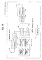
- Figure 3 is a block diagram showing an electrical circuit of a relay apparatus according to the embodiment 1 of the present invention.
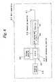
- Figure 4 is a block diagram showing an electrical circuit of a main apparatus according to the embodiment 1 of the present invention.
- reference numeral 1 denotes a vehicle, which is an ordinary four-wheel passenger automobile.
- a detection apparatus 10 is secured to each rim of four wheels 2 of the vehicle 1 so that the detection apparatus 10 is positioned within the tire.
- a relay apparatus 20 is provided in a vicinity of each wheel 2 in a vehicle side.
- a main apparatus 30 is disposed in a vicinity of a driver seat so that a display unit can be seen from the driver.
- a condition information collection apparatus according to the present embodiment includes the above described four detection apparatuses 10, four relay apparatuses 20 and one main apparatus 30.
- the detection apparatus 10 includes a sensor section 11, central processing section 12, transmission section 13, antenna 14, and battery 15 which is a power source to drive these sections.
- the sensor section 11 includes a pressure sensor 111 to detect a air pressure within tire, a temperature sensor 112 to detect a temperature within tire, and analog-to-digital (hereinafter, simply referred to as A/D) converter circuits 113 and 114.
- A/D analog-to-digital
- the pressure sensor 111 detects an air pressure within tire and outputs to the A/D converter circuit 113 an analog electrical signal corresponding to the detected air pressure value.
- the temperature sensor 112 detects a temperature within tire and outputs to the A/D converter circuit 114 an analog electrical signal corresponding to the detected temperature value.
- the A/D converter circuit 113 converts the analog electrical signal value received from the pressure sensor 111 into a digital value and outputs the value to a later-described CPU 121.
- the A/D converter circuit 114 converts the analog electrical signal value received from the temperature sensor 112 into a digital value and outputs the value to a later-described CPU 121.
- the central processing section 12 includes a known CPU 121 and storage section 122.
- the CPU 121 operates based on a program stored in a semiconductor memory of the storage section 122.
- the CPU 121 transmits wirelessly the data detected by the sensor section 11 to the relay apparatus 20 at a predetermined interval by use of electromagnetic wave of a first frequency f1.
- a setting is made such that, in transmitting the detection data, information having (1) a header indicating that the data is detection data and (2) specific identification information for each detection apparatus 10 each added to the detection data is transmitted as transmission information to the relay apparatus 20 via the transmission section 13.
- the storage section 122 includes a ROM on which the program to cause the CPU 121 to operate is recorded, and an electrically rewritable nonvolatile semiconductor memory such as EEP ROM (electrically erasable programmable read-only memory).
- EEP ROM electrically erasable programmable read-only memory
- the transmission section 13 includes a transmitter 131 and a digital-to-analog (hereinafter, simply referred to as D/A) converter circuit 132.
- the transmitter 131 converts the transmission information received from the CPU 121 into a high frequency signal of a first frequency f1 and transmits the converted signal via the antenna 14. It is noted that the output power of the high frequency signal from the transmission section 13 is set to a small value which is sufficient for the electromagnetic wave to reach the relay apparatus 20 disposed in the vicinity thereof.
- the relay apparatus 20 includes a sensor section 21, central processing section 22, reception section 23, transmission section 24, antennas 25 and 26, and a battery 27 which is a power source to drive these sections.
- the sensor section 21 includes a pressure sensor 211 to detect an atmospheric pressure outside tire in a vicinity of tire, a temperature sensor 212 to detect a temperature outside tire in a vicinity of tire, and A/D converter circuits 213 and 214.
- the pressure sensor 211 detects an atmospheric pressure outside tire in a vicinity of tire and outputs to the A/D converter circuit 213 an analog electrical signal corresponding to the detected atmospheric pressure value.
- the temperature sensor 212 detects a temperature outside tire in a vicinity of tire and outputs to the A/D converter circuit 214 an analog electrical signal corresponding to the detected temperature value.
- the A/D converter circuit 213 converts the analog electrical signal value received from the pressure sensor 211 into a digital value and outputs the value to a later-described CPU 221.
- the A/D converter circuit 214 converts the analog electrical signal value received from the temperature sensor 212 into a digital value and outputs the value to a later-described CPU 221.
- the central processing section 22 includes a known CPU 221 and storage section 222.
- the CPU 221 operates based on a program stored in a semiconductor memory of the storage section 222. With electrical power supplied to drive the CPU 221, when the detection information is received from the detection apparatus 10, data detected by the sensor section 21 as well as the received detection information is wirelessly transmitted to the main apparatus 30 by use of electromagnetic wave of a second frequency f2.
- a setting is made such that, in transmitting the information, information having (1) a header indicating that the data is detection data and (2) specific identification information for each relay apparatus 20 each added to the detection data is transmitted as transmission information to the main apparatus 30 via the transmission section 24.
- the storage section 222 includes a ROM on which a program to cause the CPU 221 to operate is recorded, and an electrically rewritable nonvolatile semiconductor memory such as EEP ROM (electrically erasable programmable read-only memory) .
- EEP ROM electrically erasable programmable read-only memory
- the reception section 23 includes a receiver 231 and an A/D converter circuit 232.
- the information transmitted from the detection apparatus 10 is received via an antenna 25 connected to the input side of the receiver 231, is subjected to wave detection, and then is outputted to the CPU 221 via the A/D converter circuit 232.
- the transmission section 24 includes a transmitter 241 and D/A converter circuit 242.
- the transmitter 241 converts the transmission information to be sent to the main apparatus 30, received from the CPU 221, into a high frequency signal of a second frequency f2 and outputs the signal to an antenna 26.
- the relay apparatus 20 is secured to the front section of a tire house.
- the installation location of the relay apparatus 20, however, may be anywhere in the vicinity of the wheel 2 in the vehicle side.
- the main apparatus 30 includes an antenna 31, reception section 32, central processing section 33 and display section 34. Electric power supplied from a battery of the vehicle is used to drive these sections.
- the reception section 32 includes a receiver 321 and A/D converter circuit 322.
- the high frequency signal of electromagnetic wave of the second frequency f2 transmitted from the relay apparatus 20 is received via the antenna 31 connected to the input side of the receiver 321, is subjected to wave detection, and then is outputted to the central processing section 33 via the A/D converter circuit 322.
- the central processing section 33 which includes a known CPU 331 and storage section 332, displays on the display section 34 the tire air pressure information, tire temperature information, etc. obtained by applying arithmetic processing to the sensor detection information received from the relay apparatus 20. At this time, the central processing section 33 acquires only the information containing the identification information of the relay apparatus 20 preliminarily stored in the storage section 332.
- the storage section 332 includes a ROM on which a program to cause the CPU 331 to operate is recorded, and an electrically rewritable nonvolatile semiconductor memory such as EEP ROM.
- the specific identification information for each relay apparatus 20 corresponding to the location of each wheel 2 is preliminarily stored in a rewritable area.
- the display section 34 displays the sensor detection information for each relay apparatus 20 received from the CPU 331. Also, the display section 34 includes a display panel 400 as shown in Figure 6. In the upper section of the display panel 400, there is drawn a graphic of the vehicle in the central section of the panel, so that the installation location of tire can be easily identified. In both sides thereof, there are disposed LEDs 401a to 401d indicating whether or not the tire air pressure is satisfactory, whose color is changed among red, yellow and green, and LEDs 402a to 402d indicating whether or not the temperature within tire is satisfactory, whose color is changed among red, yellow and green. The LEDs correspond to each tire.
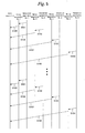
- Figure 5 is a diagram for explaining a procedure of communication between the detection apparatus 10, relay apparatus 20 and main apparatus 30.
- Figure 7 is a flowchart showing an operation of the detection apparatus 10.
- Figure 8 is a flowchart showing an operation of the relay apparatus 20.
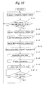
- Figure 9 is a flowchart showing an operation of the main apparatus.
- the CPU 121 of the detection apparatus 10 retrieves the pressure and temperature data within tire detected by the pressure sensor 111 and temperature sensor 112 of the sensor section 11 (SA1), and wirelessly transmits the retrieved data to the relay apparatus 20 by use of electromagnetic wave of the first frequency f1 (SA2, S101 to S104). At this time, information having (1) a header indicating that the data is detection data and (2) specific identification information for each detection apparatus 10 each added to the detection data is transmitted as transmission information to the relay apparatus 20.
- the time T1 is set to about 3 to 5 minutes but is not limited thereto; T1 may be appropriately set. Also, the timing of information transmission from each detection apparatus 10 is at random. The time taken to perform one information transmission is several tens of milliseconds.
- the CPU 221 of the relay apparatus 20 monitors whether or not the detection data is received from the detection apparatus 10 (SB1). When the detection data is received, the CPU 221 retrieves the atmospheric pressure and temperature data outside tire detected by the pressure sensor 211 and temperature sensor 212 of the sensor section 21 (SB2), and wirelessly transmits the retrieved data and the detection data received from the detection apparatus 10 to the main apparatus 30 by use of electromagnetic wave of the second frequency f2 (SB3, S105 to S108) . In transmitting the information, information having (1) a header indicating that the data is detection data and (2) specific identification information for each relay apparatus 20 each added to the above data is transmitted as transmission information to the main apparatus 30.
- the CPU 331 of the main apparatus 30 monitors whether or not the data is received from the relay apparatus 20 (SC1). When the data is received, the CPU 331 extracts the identification information of the relay apparatus 20 from the received data (SC2), and at the same time extracts the detection data from the sensor section 11 of the detection apparatus 10 and the detection data from the sensor section 21 of the relay apparatus 20 (SC3).
- the CPU 331 of the main apparatus 30 performs a data correction processing (SC4) and displays the information on the display section 34 based on the corrected data (SC5).
- SC4 data correction processing
- SC5 corrected data
- a pressure value obtained by correcting the pressure value detected by the pressure sensor 111 of the detection apparatus 10 by use of the atmospheric pressure value detected by the pressure sensor 211 of the relay apparatus 20 is defined as the air pressure value of tire.
- the management of air pressure within tire can be made more accurate, thus enabling achievement of the improvement of tire durability.
- the correction may be made by use of the known International Standard Atmosphere (ISA) of the International Civil Aviation Organization (ICAO), for example.
- the first frequency f1 and second frequency f2 may be the same or different. Also, the first frequency f1 and second frequency f2 may be a frequency of any one of the frequency bands from the Low Frequency band to the Ultra High Frequency band. However, in consideration of the miniaturization and efficiency of antenna, a frequency of the frequency bands from the Very High Frequency band to the Ultra High Frequency band is preferably employed.
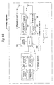
- Figure 10 is a block diagram showing an electrical circuit of a detection apparatus according to an embodiment 2 of the present invention.
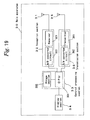
- Figure 11 is a block diagram showing an electrical circuit of a relay apparatus according to the embodiment 2 of the present invention.
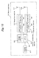
- Figure 12 is a block diagram showing an electrical circuit of a main apparatus according to the embodiment 2 of the present invention.
- a reception antenna 16 and a reception section 17 are provided in the detection apparatus; a transmission antenna 35 and a transmission section 36 are provided in the main apparatus 30; and each one of the detection apparatus 10 and relay apparatus 20 transmits data when an information request signal is received.
- a reception section 17 of the detection apparatus 10 includes a receiver 171 and an A/D converter circuit 172.
- An information request signal transmitted from the relay apparatus 20 by use of electromagnetic wave of the second frequency f2 is received via the antenna 16 connected to the input side of the receiver 171, is subjected to wave detection, and then is outputted to the CPU 121 via the A/D converter circuit 172.
- a computer program stored in the storage section 122 of the detection apparatus 10 is different from that of the embodiment 1.
- the CPU 121 transmits the detection data to the relay apparatus 20 only when an information request signal containing the self identification information is received from the relay apparatus 20.
- a computer program stored in the storage section 222 of the relay apparatus 20 is different from that of the embodiment 1.
- the CPU 221 transmits an information request signal to the detection apparatus 10 only when the information request signal having the self identification information specified therein is received from the main apparatus 30.
- the information request signal sent from the relay apparatus 20 to the detection apparatus 10 contains the identification information of the detection apparatus 10, thereby enabling specification of the detection apparatus 10.
- the transmission section 36 of the main apparatus 30 includes a transmitter 361 and D/A converter circuit 362.
- the transmitter 361 converts an information request signal to be sent to the relay apparatus 20 received from the CPU 331 into a high frequency signal of a first frequency f1, and outputs the signal to the antenna 35.
- a computer program stored in the storage section 332 of the main apparatus 30 is different from that of the embodiment 1.
- the CPU 331 transmits an information request signal to each relay apparatus 20 at a predetermined interval to acquire information from each relay apparatus 20.
- the information request signal sent from the main apparatus 30 to the relay apparatus 20 contains the identification information of the relay apparatus 20, whereby any one of the respective relay apparatuses 20 can be specified for the information request.
- Figure 13 is a diagram showing a procedure of communication between the detection apparatus 10, relay apparatus 20 and main apparatus 30.
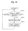
- Figure 14 is a flowchart showing an operation of the detection apparatus 10.
- Figure 15 is a flowchart showing an operation of the relay apparatus 20.
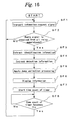
- Figure 16 is a flowchart showing an operation of the main apparatus.
- the CPU 121 of the detection apparatus 10 monitors whether or not an information request signal is received from the relay apparatus 20 (SD1).
- the CPU 221 retrieves the air pressure and temperature data within tire detected by the pressure sensor 111 and temperature sensor 112 of the sensor section 11 (SD2), and wirelessly transmits the retrieved data to the relay apparatus 20 by use of electromagnetic wave of the first frequency f1 (SD3, S203, S207, S211, S215).
- information having (1) a header indicating that the data is detection data and (2) specific identification information for each detection apparatus 10 each added to the detection data is transmitted as transmission information to the relay apparatus 20.
- the time T1 is set to about 3 to 5 minutes but is not limited thereto; T1 may be appropriately set. Also, the timing of information transmission from each detection apparatus 10 is at random. The time taken to perform one information transmission is several tens of milliseconds.
- the CPU 221 of the relay apparatus 20 monitors whether or not an information request signal is received from the main apparatus 30 (SE1).
- the CPU 221 transmits the information request signal to the detection apparatus 10 (SE2, S202, S206, S210, S214). Then, it is determined whether or not a reply signal, i.e., the detection data is received from the detection apparatus 10 (SE3).
- the CPU 221 retrieves the atmospheric pressure and temperature data outside tire detected by the pressure sensor 211 and temperature sensor 212 of the sensor section 21 (SE4), and wirelessly transmits the retrieved data and the detection data received from the detection apparatus 10 to the main apparatus 30 by use of electromagnetic wave of the second frequency f2 (SE5, S204, S208, S212, S216).
- electromagnetic wave of the second frequency f2 SE5, S204, S208, S212, S216.
- the CPU 331 of the main apparatus 30 sequentially transmits an information request signal to each relay apparatus 20 (SF1, S201, S205, S209, S213), and determines whether or not the reply signal, i.e., the detection data is received from all the relay apparatuses 20 (SF2).
- the identification information of the relay apparatus 20 is extracted from the received data (SF3), and at the same time the detection data from the sensor section 11 of the detection apparatus 10 and the detection data from the sensor section 21 of the relay apparatus 20 are extracted from the received data (SF4).
- the CPU 331 of the main apparatus 30 performs the data correction processing (SF5) .
- the display section 34 displays the information (SF6).
- the CPU 331 starts the timer count (SF7), and it is determined whether or not the time count becomes T1 (SF8). If so, the flow proceeds to the above process SF1.
- Figure 17 is a block diagram showing an electrical circuit of a detection apparatus according to an embodiment 3 of the present invention.
- Figure 18 is a block diagram showing an electrical circuit of a relay apparatus according to the embodiment 3 of the present invention.
- Figure 19 is a block diagram showing an electrical circuit of a main apparatus according to the embodiment 3 of the present invention.
- a transmission antenna 35 and a transmission section 36 are provided in the main apparatus 30; and the relay apparatus 20 transmits data when an information request signal is received from the main apparatus 30.
- the transmission section 36 of the main apparatus 30 includes a transmitter 361 and D/A converter circuit 362.
- the transmitter 361 converts an information request signal for the relay apparatus 20 received from the CPU 331 into a high frequency signal of a first frequency f1, and outputs the signal to the antenna 35.
- a computer program stored in the storage section 332 of the main apparatus 30 is different from that of the embodiment 1.
- the CPU 331 transmits the information request signal to each relay apparatus 20 at a predetermined interval T2 to acquire information from each relay apparatus 20.
- the information request signal sent from the main apparatus 30 to the relay apparatus 20 contains the identification information of the relay apparatus 20, whereby any one of the respective relay apparatuses 20 can be specified for the information request.
- the detection apparatus 10 transmits the detection data at a predetermined interval T1.
- the relay apparatus 20 stores the received detection data. Then, when receiving the information request signal from the main apparatus 30, the relay apparatus 20 transmits the stored detection data and the data detected by the sensor section 21 to the main apparatus 30.
- Figure 20 is a diagram showing a procedure of communication between the detection apparatus 10, relay apparatus 20 and main apparatus 30.
- Figure 21 is a flowchart showing an operation of the detection apparatus 10.
- Figure 22 is a flowchart showing an operation of the relay apparatus 20.
- Figure 23 is a flowchart showing an operation of the main apparatus.
- the CPU 121 of the detection apparatus 10 retrieves the pressure and temperature data within tire detected by the pressure sensor 111 and temperature sensor 112 of the sensor section 11 (SG1), and wirelessly transmits the retrieved data to the relay apparatus 20 by use of electromagnetic wave of a first frequency f1 (SG2, S301 to S304) .
- information having (1) a header indicating that the data is detection data and (2) specific identification information for each detection apparatus 10 each added to the detection data is transmitted as transmission information to the relay apparatus 20.
- the time T1 is set to about 3 to 5 minutes but is not limited thereto; T1 may be appropriately set. Also, the timing of information transmission from each detection apparatus 10 is at random. The time taken to perform one information transmission is several tens of milliseconds.
- the CPU 221 of the relay apparatus 20 monitors whether or not the detection data is received from the detection apparatus 10 (SH1).
- the CPU 221 stores the received data (SH2, S301 to S304).
- the CPU 221 monitors whether or not an information request signal is received from the main apparatus 30 (SH3).
- the CPU 221 retrieves the atmospheric pressure and temperature data outside tire detected by the pressure sensor 211 and temperature sensor 212 of the sensor section 21 (SH4), and wirelessly transmits the retrieved data and the detection data received from the detection apparatus 10 to the main apparatus 30 by use of electromagnetic wave of a second frequency f2 (SH5, S306, S308, S310, S312).
- information having (1) a header indicating that the data is detection data and (2) specific identification information for each relay apparatus 20 each added to the above data is transmitted as transmission information to the main apparatus 30. Then, the flow proceeds to the above process SH1.
- the CPU 331 of the main apparatus 30 sequentially transmits an information request signal to each relay apparatus 20 (SI1, S305, S307, S309, S311), and determines whether or not the reply signal, i.e., the detection data is received from all the relay apparatuses 20 (SI2).
- the identification information of the relay apparatus 20 is extracted from the received data (SI3), and at the same time the detection data from the sensor section 11 of the detection apparatus 10 and the detection data from the sensor section 21 of the relay apparatus 20 are extracted from the received data (SI4).
- the CPU 331 of the main apparatus 30 performs the data correction processing similar to the above described one (SI5). Based on the corrected data, the display section 34 displays the information (SI6).
- the CPU 331 starts the timer count (SI7), and it is determined whether or not the time count becomes T2 (SI8). If so, the flow proceeds to the above process SI1.
- the time T2 is set to about 3 to 5 minutes.
- outside air temperature for each wheel 2 is displayed on the liquid crystal display unit 403 of the display panel 400.
- the outside air temperature in the vicinity of each wheel detected by the temperature sensor 212 of the relay apparatus 20 the outside air temperature in the vicinity of each wheel and the temperature of each tire can be visually recognized with ease, whereby the display of LEDs 402a to 402d can be easily understood.
- the displaying of outside air temperature in the vicinity of each wheel on the liquid crystal display unit 403 may also be applied to any one of the above described embodiments.
- Figure 25 is a block diagram showing an electrical circuit of a relay apparatus according to an embodiment 5 of the present invention. Electrical circuits of the detection apparatus 10 and main apparatus 30 are similar to those of the above described embodiment 3.
- an ozone density sensor 215 is provided in the relay apparatus 20; and the degradation state of tire is displayed on the liquid crystal display unit 403 of the main apparatus 30 based on the detected ozone density.
- the sensor section 21 of the relay apparatus 20 includes the pressure sensor 211 to detect an atmospheric pressure outside tire in a vicinity of tire, the temperature sensor 212 to detect a temperature outside tire in a vicinity of tire, the ozone density sensor 215 to detect an ozone density outside tire in a vicinity of tire, and A/D converter circuits 213, 214, 216.
- the ozone density sensor 215 detects an ozone density outside tire in a vicinity of tire, and outputs an analog electrical signal corresponding to the detected ozone density to the A/D converter circuit 216.
- the A/D converter circuit 216 converts the value of the analog electrical signal received from the ozone density sensor 215 into a digital value and outputs the digital value to the CPU 221.
- a computer program stored in the storage section 222 of the relay apparatus 20 is different from that of the embodiment 3.
- the CPU 221 transmits to the main apparatus 30 the detection data received from the detection apparatus 10 and the detection data of each one of the pressure sensor 211, temperature sensor 212 and ozone density sensor 215 when the information request signal having the self identification information specified therein is received from the main apparatus 30.
- a computer program stored in the storage section 332 of the main apparatus 30 is different from that of the embodiment 3.
- the CPU 331 transmits the information request signal to each relay apparatus 20 at a predetermined interval to acquire information from each relay apparatus 20, whereby as shown in Figure 26, the degradation state of tire estimated from the ozone density as well as the above described information are displayed on the liquid crystal display unit 403.
- the CPU 331 of the main apparatus 30 sequentially transmits an information request signal to each relay apparatus 20 (SJ1), and determines whether or not the reply signal, i.e., the detection data is received from all the relay apparatuses 20 (SJ2).
- the identification information of the relay apparatus 20 is extracted from the received data (SJ3), and at the same time the detection data from the sensor section 11 of the detection apparatus 10 and the detection data from the sensor section 21 of the relay apparatus 20 are extracted from the received data (SJ4).
- the CPU 331 of the main apparatus 30 performs the data correction processing similar to the above described one (SJ5) . Also, the CPU 331 applies an integral processing to the detected ozone density data (SJ6), adds the resultant data to the integral-processing applied ozone density data which have been accumulated, and stores the accumulated data into the memory section 332 (SJ7). Then, the information based on the corrected data and stored ozone density data is displayed in the display section 34 (SJ8).
- the CPU 331 applies the integral processing to the detection data, and at the same time stores the data, and estimates the degree of degradation of the tire's surface, especially of the side wall section, based on the accumulated data to display the degree in the liquid crystal display unit 403. Accordingly, the tire's damage can be shown to the driver.
- the CPU 331 starts the timer count (SJ9), and determines whether or not the time count becomes T2 (SJ10). If so, the flow proceeds to the above process SJ1.
- each one of the above described embodiments is an example of the present invention, and the present invention is not limited only to the structures of the above described embodiments.
- the information obtained by correcting the information on air pressure and temperature of tire by use of atmospheric pressure and temperature outside tire is provided for the driver; however, any physical quantity regarding tire other than air pressure and temperature may be corrected for provision.
- the present invention can be applied to a case in which accurate information on tire is indispensable.
Abstract
Description
- The present invention relates to a tire condition information collection apparatus and a relay apparatus thereof, and more particularly to a tire condition information collection apparatus and a relay apparatus thereof, which corrects a predetermined physical quantity within tire by use of a predetermined physical quantity outside tire in a vicinity of tire, and informs of the result.
- There have hitherto been known tire monitoring systems for acquiring information on tire conditions such as pressure, temperature, etc. of the atmosphere inside tire's air chamber.
- As an exemplary technique of this type, systems for monitoring air pressure inside tire are disclosed in Japanese Patent Publication 2001-56263 (a first conventional example), Japanese Patent Publication 2000-182164 (a second conventional example), and so on.
- The tire air pressure monitoring system of the first conventional example, provided in each tire of a vehicle, has a transmitter to transmit a tire air pressure signal for each tire outputted from an air pressure sensor, and multiple reception antennas extended to a neighborhood of each tire. The tire air pressure monitoring system includes a receiver to receive the tire air pressure signal from the transmitter, a display apparatus to inform the vehicle driver of air pressure condition of each tire, and a combining unit to output selectively the maximum voltage from among the voltages induced in each reception antenna. With this combining unit, the induction voltages of each reception antenna complement each other, and at the same time a selection is performed from among the receptions of each reception antenna. Thus the signal transmitted from the transmitter can be received in a stable manner.
- Also, in the tire air pressure monitoring system of the second conventional example, a reception antenna is also provided within a receiver. Accordingly, the number of reception antennas extended to the vicinity of tire is reduced.
- Meanwhile, an exemplary tire air pressure monitoring system in which reception antennas need not to be extended to a vicinity of tire is disclosed in Japanese Patent Publication 11-254926 (a third conventional example), Japanese Patent Publication 11-240315 (a fourth conventional example), and so on.
- The third conventional example is a tire monitoring system which has a storage apparatus provided in an inner wall of tire within the air chamber of tire, and at the same time has a monitoring apparatus secured to a rim's inner wall face inside the air chamber of tire. In this system, the storage apparatus includes an antenna, a battery and an electronic chip; the monitoring apparatus includes a battery, an antenna, and a microchip connected to an amplifier. The battery of the monitoring apparatus is larger in capacity than that of the storage apparatus.
- With the above described structure, in the system of the third conventional example, information on physical quantity within the tire's air chamber detected by the storage apparatus is transmitted by use of electromagnetic wave; the information is received by the monitoring apparatus. Also, the monitoring apparatus transmits the received information by use of electromagnetic wave having a larger output power than that of the storage apparatus. Accordingly, the power consumption of battery for the storage apparatus and monitoring apparatus can be reduced, thus enabling the continuous operation of the system without frequently exchanging the batteries.
- In addition, in the third conventional example, the battery of the monitoring apparatus is separately disposed outside the tire' s air chamber and connected to the monitoring apparatus via a connector provided by penetrating the rim, whereby the exchange of the battery of the monitoring apparatus is made easy.
- In the fourth conventional example substantially similar to the third conventional example, information on physical quantity within the tire's air chamber detected by a tire tag is transmitted by use of electromagnetic wave; the information is received by a transponder. In addition, the transponder transmits the received information by use of electromagnetic wave having a larger output power than that of the tire tag. Accordingly, the power consumption of battery for the tire tag and transponder can be reduced, thus enabling the continuous operation of the system without frequently exchanging the batteries.
- Patent document 1: Japanese Patent Publication 2001-56263
- Patent document 2: Japanese Patent Publication 2000-182164
- Patent document 3: Japanese Patent Publication 11-254926
- Patent document 4: Japanese Patent Publication 11-240315
- However, when the above described physical quantity of tire, such as air pressure, is detected, the results of detection can be affected by a physical quantity outside tire. For example, when air pressure inside tire is monitored, even with the same tire, the tire's temperature varies depending on whether the tire is in the sunshine or in the shade; the difference in the tire's temperature also causes a difference in the air pressure inside tire. In addition, the air pressure outside tire varies according to the altitude of the vehicle's location. Thus, the differences in the results of detection can arise, thus making it impossible to obtain correct information.
- To address the above described problems, an object of the present invention is to provide a tire condition information collection apparatus and a relay apparatus thereof, which corrects a predetermined physical quantity inside tire by a predetermined physical quantity outside tire in a vicinity of tire, and informs of the result.
- According to the present invention, there is provided a tire condition information collection apparatus for detecting a predetermined physical quantity of vehicle tire to inform a driver or an administrator of the information on tire condition, characterized mainly by comprising: a plurality of detection apparatuses mounted on each tire; a plurality of relay apparatuses disposed in a predetermined vehicle side position in a vicinity of each tire; and a main apparatus for informing the driver or administrator of a result of detection of the physical quantity of tire, wherein the detection apparatus includes: a sensor circuit which detects a predetermined first physical quantity within tire to output an electrical signal corresponding to the first physical quantity; and wireless communication means for wirelessly transmitting the result of detection as information within tire by use of electromagnetic wave of a first frequency based on the electrical signal outputted from the sensor circuit, and the relay apparatus includes: reception means for receiving the information within tire transmitted from the wireless communication means of the detection apparatus; outside-tire information detection means for detecting a predetermined second physical quantity outside tire in a vicinity of the self apparatus as information outside tire; and transmission means for wirelessly transmitting the information within tire and the information outside tire by use of electromagnetic wave of a second frequency, and the main apparatus includes: reception means for receiving the information within tire and the information outside tire transmitted from the relay apparatus; information correction means for correcting the first physical quantity based on the information within tire by use of the second physical quantity based on the information outside tire according to the received information within tire and information outside tire; and information informing means for informing of the information corrected by the information correction means as information on tire condition.
- With the tire condition information collection apparatus according to the present invention, it is possible to inform of the information obtained by correcting the detected first physical quantity, such as air pressure inside tire, by use of the detected second physical quantity, such as outside air pressure in the vicinity of tire, thus enabling provision of correct information for the driver or administrator.
- Also, with the relay apparatus according to the present invention, the second physical quantity outside tire in the vicinity of tire can be detected, so that the information thereon can be supplied to the main apparatus along with the information on the first physical quantity detected by the detection apparatus. Accordingly, the above described condition collection apparatus can be easily constructed.
- The above and other objects and the attendant advantages and features of the present invention will become readily apparent by reference to the following description when considered in conjunction with the accompanying drawings.
-
- Figure 1 is a diagram showing an overall structure of a tire condition information collection apparatus according to an
embodiment 1 of the present invention; - Figure 2 is a block diagram showing an electrical circuit of a detection apparatus according to the
embodiment 1 of the present invention; - Figure 3 is a block diagram showing an electrical circuit of a relay apparatus according to the
embodiment 1 of the present invention; - Figure 4 is a block diagram showing an electrical circuit of a main apparatus according to the
embodiment 1 of the present invention; - Figure 5 is a diagram showing a procedure of communication between the detection apparatus, relay apparatus and main apparatus according to the
embodiment 1 of the present invention; - Figure 6 is a diagram showing a display panel of the main apparatus according to the
embodiment 1 of the present invention; - Figure 7 is a flowchart showing an operation of the detection apparatus according to the
embodiment 1 of the present invention; - Figure 8 is a flowchart showing an operation of the relay apparatus according to the
embodiment 1 of the present invention; - Figure 9 is a flowchart showing an operation of the main apparatus according to the
embodiment 1 of the present invention; - Figure 10 is a block diagram showing an electrical circuit of a detection apparatus according to an
embodiment 2 of the present invention; - Figure 11 is a block diagram showing an electrical circuit of a relay apparatus according to the
embodiment 2 of the present invention; - Figure 12 is a block diagram showing an electrical circuit of a main apparatus according to the
embodiment 2 of the present invention; - Figure 13 is a diagram showing a procedure of communication between the detection apparatus, relay apparatus and main apparatus according to the
embodiment 2 of the present invention; - Figure 14 is a flowchart showing an operation of the detection apparatus according to the
embodiment 2 of the present invention; - Figure 15 is a flowchart showing an operation of the relay apparatus according to the
embodiment 2 of the present invention; - Figure 16 is a flowchart showing an operation of the main apparatus according to the
embodiment 2 of the present invention; - Figure 17 is a block diagram showing an electrical circuit of a detection apparatus according to an
embodiment 3 of the present invention; - Figure 18 is a block diagram showing an electrical circuit of a relay apparatus according to the
embodiment 3 of the present invention; - Figure 19 is a block diagram showing an electrical circuit of a main apparatus according to the
embodiment 3 of the present invention; - Figure 20 is a diagram showing a procedure of communication between the detection apparatus, relay apparatus and main apparatus according to the
embodiment 3 of the present invention; - Figure 21 is a flowchart showing an operation of the detection apparatus according to the
embodiment 3 of the present invention; - Figure 22 is a flowchart showing an operation of the relay apparatus according to the
embodiment 3 of the present invention; - Figure 23 is a flowchart showing an operation of the main apparatus according to the
embodiment 3 of the present invention; - Figure 24 is a diagram showing a display panel of a main apparatus according to an
embodiment 4 of the present invention; - Figure 25 is a block diagram showing an electrical circuit of a relay apparatus according to an
embodiment 5 of the present invention; - Figure 26 is a diagram showing a display panel of a main apparatus according to the
embodiment 5 of the present invention; and - Figure 27 is a flowchart showing an operation of the main apparatus according to the
embodiment 5 of the present invention. - 1 ... vehicle, 2 ... wheel, 10 ... detection apparatus, 11 ... sensor section, 12 ... central processing section, 13 ... transmission section, 14 ... antenna, 15 ... battery, 16 ... antenna, 17 ... reception section, 111 ... pressure sensor, 112 ... temperature sensor, 113, 114 ... A/D converter circuit, 121 .... CPU, 122 ... storage section, 131 ... transmitter, 132 ... D/A converter circuit, 171 ... receiver, 172 ... A/D converter circuit, 20 ... relay apparatus, 21 ... sensor section, 22 ... central processing section, 23 ... reception section, 24 ... transmission section, 25, 26 ... antenna, 27 ... battery, 211 ... pressure sensor, 212 ... temperature sensor, 213, 214 ... A/D converter circuit, 221 ... CPU, 222 ... storage section, 231 ... receiver, 232 ... A/D converter circuit, 241 ... transmitter, 242 ... D/A converter circuit, 30 ... main apparatus, 31 ... antenna, 32 ... reception section, 33 ... central processing section, 34 ... display section, 35 ... antenna, 36 ... transmission section, 321 ... receiver, 322 ... A/D converter circuit, 331 ... CPU, 332 ... storage section, 361 ... transmitter, 362 ... D/A converter circuit, 400 ... display panel, 401a to 401d, 402a to 402d ....LED, 403 ... liquid crystal display unit
- An embodiment of the present invention will be described below with reference to the accompanying drawings.
- Figure 1 is a diagram showing an overall structure of a tire condition information collection apparatus according to an
embodiment 1 of the present invention. Figure 2 is a block diagram showing an electrical circuit of a detection apparatus according to theembodiment 1 of the present invention. Figure 3 is a block diagram showing an electrical circuit of a relay apparatus according to theembodiment 1 of the present invention. Figure 4 is a block diagram showing an electrical circuit of a main apparatus according to theembodiment 1 of the present invention. - Referring to Figure 1,
reference numeral 1 denotes a vehicle, which is an ordinary four-wheel passenger automobile. Adetection apparatus 10 is secured to each rim of fourwheels 2 of thevehicle 1 so that thedetection apparatus 10 is positioned within the tire. Also, arelay apparatus 20 is provided in a vicinity of eachwheel 2 in a vehicle side. In addition, amain apparatus 30 is disposed in a vicinity of a driver seat so that a display unit can be seen from the driver. A condition information collection apparatus according to the present embodiment includes the above described fourdetection apparatuses 10, fourrelay apparatuses 20 and onemain apparatus 30. - As shown in Figure 2, the
detection apparatus 10 includes asensor section 11, central processing section 12,transmission section 13,antenna 14, andbattery 15 which is a power source to drive these sections. - The
sensor section 11 includes apressure sensor 111 to detect a air pressure within tire, atemperature sensor 112 to detect a temperature within tire, and analog-to-digital (hereinafter, simply referred to as A/D)converter circuits - The
pressure sensor 111 detects an air pressure within tire and outputs to the A/D converter circuit 113 an analog electrical signal corresponding to the detected air pressure value. - The
temperature sensor 112 detects a temperature within tire and outputs to the A/D converter circuit 114 an analog electrical signal corresponding to the detected temperature value. - The A/
D converter circuit 113 converts the analog electrical signal value received from thepressure sensor 111 into a digital value and outputs the value to a later-describedCPU 121. - The A/
D converter circuit 114 converts the analog electrical signal value received from thetemperature sensor 112 into a digital value and outputs the value to a later-describedCPU 121. - The central processing section 12 includes a known
CPU 121 andstorage section 122. TheCPU 121 operates based on a program stored in a semiconductor memory of thestorage section 122. When electrical power is supplied to drive theCPU 121, theCPU 121 transmits wirelessly the data detected by thesensor section 11 to therelay apparatus 20 at a predetermined interval by use of electromagnetic wave of a first frequency f1. - Also, in the program of the
CPU 121, a setting is made such that, in transmitting the detection data, information having (1) a header indicating that the data is detection data and (2) specific identification information for eachdetection apparatus 10 each added to the detection data is transmitted as transmission information to therelay apparatus 20 via thetransmission section 13. - The
storage section 122 includes a ROM on which the program to cause theCPU 121 to operate is recorded, and an electrically rewritable nonvolatile semiconductor memory such as EEP ROM (electrically erasable programmable read-only memory). The specific identification information for eachdetection apparatus 10 is preliminarily stored in a non-rewritable area within thestorage section 122 during manufacture. - The
transmission section 13 includes atransmitter 131 and a digital-to-analog (hereinafter, simply referred to as D/A)converter circuit 132. Thetransmitter 131 converts the transmission information received from theCPU 121 into a high frequency signal of a first frequency f1 and transmits the converted signal via theantenna 14. It is noted that the output power of the high frequency signal from thetransmission section 13 is set to a small value which is sufficient for the electromagnetic wave to reach therelay apparatus 20 disposed in the vicinity thereof. - As shown in Figure 3, the
relay apparatus 20 includes asensor section 21,central processing section 22, reception section 23,transmission section 24,antennas battery 27 which is a power source to drive these sections. - The
sensor section 21 includes apressure sensor 211 to detect an atmospheric pressure outside tire in a vicinity of tire, atemperature sensor 212 to detect a temperature outside tire in a vicinity of tire, and A/D converter circuits - The
pressure sensor 211 detects an atmospheric pressure outside tire in a vicinity of tire and outputs to the A/D converter circuit 213 an analog electrical signal corresponding to the detected atmospheric pressure value. - The
temperature sensor 212 detects a temperature outside tire in a vicinity of tire and outputs to the A/D converter circuit 214 an analog electrical signal corresponding to the detected temperature value. - The A/
D converter circuit 213 converts the analog electrical signal value received from thepressure sensor 211 into a digital value and outputs the value to a later-describedCPU 221. - The A/
D converter circuit 214 converts the analog electrical signal value received from thetemperature sensor 212 into a digital value and outputs the value to a later-describedCPU 221. - The
central processing section 22 includes a knownCPU 221 andstorage section 222. TheCPU 221 operates based on a program stored in a semiconductor memory of thestorage section 222. With electrical power supplied to drive theCPU 221, when the detection information is received from thedetection apparatus 10, data detected by thesensor section 21 as well as the received detection information is wirelessly transmitted to themain apparatus 30 by use of electromagnetic wave of a second frequency f2. - Also, in the program of the
CPU 221, a setting is made such that, in transmitting the information, information having (1) a header indicating that the data is detection data and (2) specific identification information for eachrelay apparatus 20 each added to the detection data is transmitted as transmission information to themain apparatus 30 via thetransmission section 24. - The
storage section 222 includes a ROM on which a program to cause theCPU 221 to operate is recorded, and an electrically rewritable nonvolatile semiconductor memory such as EEP ROM (electrically erasable programmable read-only memory) . The specific identification information for eachrelay apparatus 20 is preliminarily stored in a non-rewritable area within thestorage section 222 during manufacture. - The reception section 23 includes a
receiver 231 and an A/D converter circuit 232. The information transmitted from thedetection apparatus 10 is received via anantenna 25 connected to the input side of thereceiver 231, is subjected to wave detection, and then is outputted to theCPU 221 via the A/D converter circuit 232. - The
transmission section 24 includes atransmitter 241 and D/A converter circuit 242. Thetransmitter 241 converts the transmission information to be sent to themain apparatus 30, received from theCPU 221, into a high frequency signal of a second frequency f2 and outputs the signal to anantenna 26. - According to the embodiment, the
relay apparatus 20 is secured to the front section of a tire house. The installation location of therelay apparatus 20, however, may be anywhere in the vicinity of thewheel 2 in the vehicle side. - As shown in Figure 4, the
main apparatus 30 includes anantenna 31, reception section 32,central processing section 33 anddisplay section 34. Electric power supplied from a battery of the vehicle is used to drive these sections. - The reception section 32 includes a
receiver 321 and A/D converter circuit 322. The high frequency signal of electromagnetic wave of the second frequency f2 transmitted from therelay apparatus 20 is received via theantenna 31 connected to the input side of thereceiver 321, is subjected to wave detection, and then is outputted to thecentral processing section 33 via the A/D converter circuit 322. - The
central processing section 33, which includes a knownCPU 331 andstorage section 332, displays on thedisplay section 34 the tire air pressure information, tire temperature information, etc. obtained by applying arithmetic processing to the sensor detection information received from therelay apparatus 20. At this time, thecentral processing section 33 acquires only the information containing the identification information of therelay apparatus 20 preliminarily stored in thestorage section 332. - The
storage section 332 includes a ROM on which a program to cause theCPU 331 to operate is recorded, and an electrically rewritable nonvolatile semiconductor memory such as EEP ROM. The specific identification information for eachrelay apparatus 20 corresponding to the location of eachwheel 2 is preliminarily stored in a rewritable area. - The
display section 34 displays the sensor detection information for eachrelay apparatus 20 received from theCPU 331. Also, thedisplay section 34 includes adisplay panel 400 as shown in Figure 6. In the upper section of thedisplay panel 400, there is drawn a graphic of the vehicle in the central section of the panel, so that the installation location of tire can be easily identified. In both sides thereof, there aredisposed LEDs 401a to 401d indicating whether or not the tire air pressure is satisfactory, whose color is changed among red, yellow and green, andLEDs 402a to 402d indicating whether or not the temperature within tire is satisfactory, whose color is changed among red, yellow and green. The LEDs correspond to each tire. By employing such LEDs of three-color type, three conditions, i.e., abnormal condition, caution-needed condition and normal condition can be visually recognized with ease. In addition, in the lower section of thedisplay panel 400, there is disposed a liquidcrystal display unit 403 so that the air pressure and temperature of each tire are numerically displayed. Accordingly, more detailed detection information can be known. - An operation of the tire condition information collection apparatus having the above described configuration will now be described with reference to the flowcharts shown in Figures 5 and 7 to 9. Figure 5 is a diagram for explaining a procedure of communication between the
detection apparatus 10,relay apparatus 20 andmain apparatus 30. Figure 7 is a flowchart showing an operation of thedetection apparatus 10. Figure 8 is a flowchart showing an operation of therelay apparatus 20. Figure 9 is a flowchart showing an operation of the main apparatus. - The
CPU 121 of thedetection apparatus 10 retrieves the pressure and temperature data within tire detected by thepressure sensor 111 andtemperature sensor 112 of the sensor section 11 (SA1), and wirelessly transmits the retrieved data to therelay apparatus 20 by use of electromagnetic wave of the first frequency f1 (SA2, S101 to S104). At this time, information having (1) a header indicating that the data is detection data and (2) specific identification information for eachdetection apparatus 10 each added to the detection data is transmitted as transmission information to therelay apparatus 20. - Then, it is determined whether or not the time count of a timer becomes T1 (SA3). If so, the timer is reset (SA4), and the flow proceeds to the above process SA1. According to the embodiment, the time T1 is set to about 3 to 5 minutes but is not limited thereto; T1 may be appropriately set. Also, the timing of information transmission from each
detection apparatus 10 is at random. The time taken to perform one information transmission is several tens of milliseconds. - The
CPU 221 of therelay apparatus 20 monitors whether or not the detection data is received from the detection apparatus 10 (SB1). When the detection data is received, theCPU 221 retrieves the atmospheric pressure and temperature data outside tire detected by thepressure sensor 211 andtemperature sensor 212 of the sensor section 21 (SB2), and wirelessly transmits the retrieved data and the detection data received from thedetection apparatus 10 to themain apparatus 30 by use of electromagnetic wave of the second frequency f2 (SB3, S105 to S108) . In transmitting the information, information having (1) a header indicating that the data is detection data and (2) specific identification information for eachrelay apparatus 20 each added to the above data is transmitted as transmission information to themain apparatus 30. - The
CPU 331 of themain apparatus 30 monitors whether or not the data is received from the relay apparatus 20 (SC1). When the data is received, theCPU 331 extracts the identification information of therelay apparatus 20 from the received data (SC2), and at the same time extracts the detection data from thesensor section 11 of thedetection apparatus 10 and the detection data from thesensor section 21 of the relay apparatus 20 (SC3). - Then; the
CPU 331 of themain apparatus 30 performs a data correction processing (SC4) and displays the information on thedisplay section 34 based on the corrected data (SC5). - With the above described data correction processing, a pressure value obtained by correcting the pressure value detected by the
pressure sensor 111 of thedetection apparatus 10 by use of the atmospheric pressure value detected by thepressure sensor 211 of therelay apparatus 20 is defined as the air pressure value of tire. In addition, it is determined whether or not the temperature value of tire detected by thetemperature sensor 112 of thedetection apparatus 10 is normal relative to the outside air temperature value detected by thetemperature sensor 212 of therelay apparatus 20. - While pressure within tire is usually managed by use of gauge pressure (relative value), an absolute value is detected by the
pressure sensor 111. Thus, the detected pressure within tire varies according to the change of atmospheric pressure. Accordingly, in the present embodiment, a gauge pressure obtained by correcting the influence given by the change of atmospheric pressure by use of the following formula (1) is displayed as pressure within tire.
- With this correction, the management of air pressure within tire can be made more accurate, thus enabling achievement of the improvement of tire durability. Also, the correction may be made by use of the known International Standard Atmosphere (ISA) of the International Civil Aviation Organization (ICAO), for example.
- Also, when the change of temperature within tire is large relative to the temperature rise around tire, it can be presumed that the tire load is large. Accordingly, it is possible to accurately inform of whether or not the tire temperature is normal, thus enabling achievement of the improvement of safety.
- The first frequency f1 and second frequency f2 may be the same or different. Also, the first frequency f1 and second frequency f2 may be a frequency of any one of the frequency bands from the Low Frequency band to the Ultra High Frequency band. However, in consideration of the miniaturization and efficiency of antenna, a frequency of the frequency bands from the Very High Frequency band to the Ultra High Frequency band is preferably employed.
- Figure 10 is a block diagram showing an electrical circuit of a detection apparatus according to an
embodiment 2 of the present invention. Figure 11 is a block diagram showing an electrical circuit of a relay apparatus according to theembodiment 2 of the present invention. Figure 12 is a block diagram showing an electrical circuit of a main apparatus according to theembodiment 2 of the present invention. - In these drawings, the same reference numerals are applied to parts corresponding to the
embodiment 1, and an explanation thereof is omitted. The difference between theembodiment 2 and the above describedembodiment 1 is that: a reception antenna 16 and areception section 17 are provided in the detection apparatus; atransmission antenna 35 and atransmission section 36 are provided in themain apparatus 30; and each one of thedetection apparatus 10 andrelay apparatus 20 transmits data when an information request signal is received. - A
reception section 17 of thedetection apparatus 10 includes areceiver 171 and an A/D converter circuit 172. An information request signal transmitted from therelay apparatus 20 by use of electromagnetic wave of the second frequency f2 is received via the antenna 16 connected to the input side of thereceiver 171, is subjected to wave detection, and then is outputted to theCPU 121 via the A/D converter circuit 172. - A computer program stored in the
storage section 122 of thedetection apparatus 10 is different from that of theembodiment 1. With this program, theCPU 121 transmits the detection data to therelay apparatus 20 only when an information request signal containing the self identification information is received from therelay apparatus 20. - Also, a computer program stored in the
storage section 222 of therelay apparatus 20 is different from that of theembodiment 1. With this program, theCPU 221 transmits an information request signal to thedetection apparatus 10 only when the information request signal having the self identification information specified therein is received from themain apparatus 30. The information request signal sent from therelay apparatus 20 to thedetection apparatus 10 contains the identification information of thedetection apparatus 10, thereby enabling specification of thedetection apparatus 10. - The
transmission section 36 of themain apparatus 30 includes atransmitter 361 and D/A converter circuit 362. Thetransmitter 361 converts an information request signal to be sent to therelay apparatus 20 received from theCPU 331 into a high frequency signal of a first frequency f1, and outputs the signal to theantenna 35. - Also, a computer program stored in the
storage section 332 of themain apparatus 30 is different from that of theembodiment 1. With this program, theCPU 331 transmits an information request signal to eachrelay apparatus 20 at a predetermined interval to acquire information from eachrelay apparatus 20. The information request signal sent from themain apparatus 30 to therelay apparatus 20 contains the identification information of therelay apparatus 20, whereby any one of therespective relay apparatuses 20 can be specified for the information request. - An operation of the tire condition information collection apparatus having the above described configuration will now be described with reference to the flowcharts shown in Figures 13 and 14 to 16. Figure 13 is a diagram showing a procedure of communication between the
detection apparatus 10,relay apparatus 20 andmain apparatus 30. Figure 14 is a flowchart showing an operation of thedetection apparatus 10. Figure 15 is a flowchart showing an operation of therelay apparatus 20. Figure 16 is a flowchart showing an operation of the main apparatus. - The
CPU 121 of thedetection apparatus 10 monitors whether or not an information request signal is received from the relay apparatus 20 (SD1). When the information request signal is received (S202, S206, S210, S214), theCPU 221 retrieves the air pressure and temperature data within tire detected by thepressure sensor 111 andtemperature sensor 112 of the sensor section 11 (SD2), and wirelessly transmits the retrieved data to therelay apparatus 20 by use of electromagnetic wave of the first frequency f1 (SD3, S203, S207, S211, S215). At this time, information having (1) a header indicating that the data is detection data and (2) specific identification information for eachdetection apparatus 10 each added to the detection data is transmitted as transmission information to therelay apparatus 20. - Then, it is determined whether or not the time count of a timer becomes T1. If so, the timer is reset, and the flow proceeds to the above process SD1. According to the embodiment, the time T1 is set to about 3 to 5 minutes but is not limited thereto; T1 may be appropriately set. Also, the timing of information transmission from each
detection apparatus 10 is at random. The time taken to perform one information transmission is several tens of milliseconds. - The
CPU 221 of therelay apparatus 20 monitors whether or not an information request signal is received from the main apparatus 30 (SE1). When the information request signal is received (S201, S205, S209, S213), theCPU 221 transmits the information request signal to the detection apparatus 10 (SE2, S202, S206, S210, S214). Then, it is determined whether or not a reply signal, i.e., the detection data is received from the detection apparatus 10 (SE3). When it is determined that the detection data is received (S203, S207, S211, S215), theCPU 221 retrieves the atmospheric pressure and temperature data outside tire detected by thepressure sensor 211 andtemperature sensor 212 of the sensor section 21 (SE4), and wirelessly transmits the retrieved data and the detection data received from thedetection apparatus 10 to themain apparatus 30 by use of electromagnetic wave of the second frequency f2 (SE5, S204, S208, S212, S216). At this time, information having (1) a header indicating that the data is detection data and (2) specific identification information for eachrelay apparatus 20 each added to the above data is transmitted as transmission information to themain apparatus 30. - The
CPU 331 of themain apparatus 30 sequentially transmits an information request signal to each relay apparatus 20 (SF1, S201, S205, S209, S213), and determines whether or not the reply signal, i.e., the detection data is received from all the relay apparatuses 20 (SF2). When it is determined that each detection data is received (S204, S208, S212, S216), the identification information of therelay apparatus 20 is extracted from the received data (SF3), and at the same time the detection data from thesensor section 11 of thedetection apparatus 10 and the detection data from thesensor section 21 of therelay apparatus 20 are extracted from the received data (SF4). - Then, the
CPU 331 of themain apparatus 30 performs the data correction processing (SF5) . Based on the corrected data, thedisplay section 34 displays the information (SF6). - Then, the
CPU 331 starts the timer count (SF7), and it is determined whether or not the time count becomes T1 (SF8). If so, the flow proceeds to the above process SF1. - Figure 17 is a block diagram showing an electrical circuit of a detection apparatus according to an
embodiment 3 of the present invention. Figure 18 is a block diagram showing an electrical circuit of a relay apparatus according to theembodiment 3 of the present invention. Figure 19 is a block diagram showing an electrical circuit of a main apparatus according to theembodiment 3 of the present invention. - In these drawings, the same reference numerals are applied to parts corresponding to the
embodiment 1, and an explanation thereof is omitted. The difference between theembodiment 3 and the above describedembodiment 1 is that: atransmission antenna 35 and atransmission section 36 are provided in themain apparatus 30; and therelay apparatus 20 transmits data when an information request signal is received from themain apparatus 30. - The
transmission section 36 of themain apparatus 30 includes atransmitter 361 and D/A converter circuit 362. Thetransmitter 361 converts an information request signal for therelay apparatus 20 received from theCPU 331 into a high frequency signal of a first frequency f1, and outputs the signal to theantenna 35. - A computer program stored in the
storage section 332 of themain apparatus 30 is different from that of theembodiment 1. With this program, theCPU 331 transmits the information request signal to eachrelay apparatus 20 at a predetermined interval T2 to acquire information from eachrelay apparatus 20. The information request signal sent from themain apparatus 30 to therelay apparatus 20 contains the identification information of therelay apparatus 20, whereby any one of therespective relay apparatuses 20 can be specified for the information request. - According to the present embodiment, similarly to the
embodiment 1, thedetection apparatus 10 transmits the detection data at a predetermined interval T1. When receiving the data, therelay apparatus 20 stores the received detection data. Then, when receiving the information request signal from themain apparatus 30, therelay apparatus 20 transmits the stored detection data and the data detected by thesensor section 21 to themain apparatus 30. - A detailed operation of the present embodiment will be described below with reference to the flowcharts shown in Figures 20 and 21 to 23. Figure 20 is a diagram showing a procedure of communication between the
detection apparatus 10,relay apparatus 20 andmain apparatus 30. Figure 21 is a flowchart showing an operation of thedetection apparatus 10. Figure 22 is a flowchart showing an operation of therelay apparatus 20. Figure 23 is a flowchart showing an operation of the main apparatus. - The
CPU 121 of thedetection apparatus 10 retrieves the pressure and temperature data within tire detected by thepressure sensor 111 andtemperature sensor 112 of the sensor section 11 (SG1), and wirelessly transmits the retrieved data to therelay apparatus 20 by use of electromagnetic wave of a first frequency f1 (SG2, S301 to S304) . At this time, information having (1) a header indicating that the data is detection data and (2) specific identification information for eachdetection apparatus 10 each added to the detection data is transmitted as transmission information to therelay apparatus 20. - Then, it is determined whether or not the time count of a timer becomes T1 (SG3). If so, the timer is reset (SG4), and the flow proceeds to the above process SG1. According to the embodiment, the time T1 is set to about 3 to 5 minutes but is not limited thereto; T1 may be appropriately set. Also, the timing of information transmission from each
detection apparatus 10 is at random. The time taken to perform one information transmission is several tens of milliseconds. - The
CPU 221 of therelay apparatus 20 monitors whether or not the detection data is received from the detection apparatus 10 (SH1). When the detection data is received, theCPU 221 stores the received data (SH2, S301 to S304). Then, theCPU 221 monitors whether or not an information request signal is received from the main apparatus 30 (SH3). When the information request signal is received (S305, S307, S309, S311), theCPU 221 retrieves the atmospheric pressure and temperature data outside tire detected by thepressure sensor 211 andtemperature sensor 212 of the sensor section 21 (SH4), and wirelessly transmits the retrieved data and the detection data received from thedetection apparatus 10 to themain apparatus 30 by use of electromagnetic wave of a second frequency f2 (SH5, S306, S308, S310, S312). In transmitting the information, information having (1) a header indicating that the data is detection data and (2) specific identification information for eachrelay apparatus 20 each added to the above data is transmitted as transmission information to themain apparatus 30. Then, the flow proceeds to the above process SH1. - The
CPU 331 of themain apparatus 30 sequentially transmits an information request signal to each relay apparatus 20 (SI1, S305, S307, S309, S311), and determines whether or not the reply signal, i.e., the detection data is received from all the relay apparatuses 20 (SI2). When it is determined that each detection data is received from all the relay apparatuses 20 (S306, S308, S310, 312), the identification information of therelay apparatus 20 is extracted from the received data (SI3), and at the same time the detection data from thesensor section 11 of thedetection apparatus 10 and the detection data from thesensor section 21 of therelay apparatus 20 are extracted from the received data (SI4). - Then, the
CPU 331 of themain apparatus 30 performs the data correction processing similar to the above described one (SI5). Based on the corrected data, thedisplay section 34 displays the information (SI6). - Then, the
CPU 331 starts the timer count (SI7), and it is determined whether or not the time count becomes T2 (SI8). If so, the flow proceeds to the above process SI1. According to the present embodiment, the time T2 is set to about 3 to 5 minutes. - According to an
embodiment 4, as shown in Figure 24, outside air temperature for eachwheel 2 is displayed on the liquidcrystal display unit 403 of thedisplay panel 400. By displaying, in this way, the outside air temperature in the vicinity of each wheel detected by thetemperature sensor 212 of therelay apparatus 20, the outside air temperature in the vicinity of each wheel and the temperature of each tire can be visually recognized with ease, whereby the display ofLEDs 402a to 402d can be easily understood. The displaying of outside air temperature in the vicinity of each wheel on the liquidcrystal display unit 403 may also be applied to any one of the above described embodiments. - Figure 25 is a block diagram showing an electrical circuit of a relay apparatus according to an
embodiment 5 of the present invention. Electrical circuits of thedetection apparatus 10 andmain apparatus 30 are similar to those of the above describedembodiment 3. - In these drawings, the same reference numerals are applied to parts corresponding to the
embodiment 3, and an explanation thereof is omitted. The difference between theembodiment 5 and the above describedembodiment 3 is that: anozone density sensor 215 is provided in therelay apparatus 20; and the degradation state of tire is displayed on the liquidcrystal display unit 403 of themain apparatus 30 based on the detected ozone density. - Specifically, the
sensor section 21 of therelay apparatus 20 includes thepressure sensor 211 to detect an atmospheric pressure outside tire in a vicinity of tire, thetemperature sensor 212 to detect a temperature outside tire in a vicinity of tire, theozone density sensor 215 to detect an ozone density outside tire in a vicinity of tire, and A/D converter circuits - The
ozone density sensor 215 detects an ozone density outside tire in a vicinity of tire, and outputs an analog electrical signal corresponding to the detected ozone density to the A/D converter circuit 216. - The A/
D converter circuit 216 converts the value of the analog electrical signal received from theozone density sensor 215 into a digital value and outputs the digital value to theCPU 221. - Also, a computer program stored in the
storage section 222 of therelay apparatus 20 is different from that of theembodiment 3. With this program, theCPU 221 transmits to themain apparatus 30 the detection data received from thedetection apparatus 10 and the detection data of each one of thepressure sensor 211,temperature sensor 212 andozone density sensor 215 when the information request signal having the self identification information specified therein is received from themain apparatus 30. - A computer program stored in the
storage section 332 of themain apparatus 30 is different from that of theembodiment 3. With this program, theCPU 331 transmits the information request signal to eachrelay apparatus 20 at a predetermined interval to acquire information from eachrelay apparatus 20, whereby as shown in Figure 26, the degradation state of tire estimated from the ozone density as well as the above described information are displayed on the liquidcrystal display unit 403. - Specifically, as shown in the flowchart of Figure 27, the
CPU 331 of themain apparatus 30 sequentially transmits an information request signal to each relay apparatus 20 (SJ1), and determines whether or not the reply signal, i.e., the detection data is received from all the relay apparatuses 20 (SJ2). When it is determined that the detection data is received from all therelay apparatuses 20, the identification information of therelay apparatus 20 is extracted from the received data (SJ3), and at the same time the detection data from thesensor section 11 of thedetection apparatus 10 and the detection data from thesensor section 21 of therelay apparatus 20 are extracted from the received data (SJ4). - Then, the
CPU 331 of themain apparatus 30 performs the data correction processing similar to the above described one (SJ5) . Also, theCPU 331 applies an integral processing to the detected ozone density data (SJ6), adds the resultant data to the integral-processing applied ozone density data which have been accumulated, and stores the accumulated data into the memory section 332 (SJ7). Then, the information based on the corrected data and stored ozone density data is displayed in the display section 34 (SJ8). - Regarding the ozone density in a vicinity of tire, the
CPU 331 applies the integral processing to the detection data, and at the same time stores the data, and estimates the degree of degradation of the tire's surface, especially of the side wall section, based on the accumulated data to display the degree in the liquidcrystal display unit 403. Accordingly, the tire's damage can be shown to the driver. - Then, the
CPU 331 starts the timer count (SJ9), and determines whether or not the time count becomes T2 (SJ10). If so, the flow proceeds to the above process SJ1. - Each one of the above described embodiments is an example of the present invention, and the present invention is not limited only to the structures of the above described embodiments. For example, according to the above described embodiments, the information obtained by correcting the information on air pressure and temperature of tire by use of atmospheric pressure and temperature outside tire is provided for the driver; however, any physical quantity regarding tire other than air pressure and temperature may be corrected for provision.
- It is possible to inform of the information obtained by correcting the detected first physical quantity such as air pressure within tire by use of the detected second physical quantity such as outside air pressure in a vicinity of tire. Accordingly, the present invention can be applied to a case in which accurate information on tire is indispensable.
Claims (16)
- A tire condition information collection apparatus for detecting a predetermined physical quantity of vehicle tire to inform a driver or an administrator of the information on tire condition, the tire condition information collection apparatus comprising: a plurality of detection apparatuses mounted on each tire; a plurality of relay apparatuses disposed in a predetermined vehicle side position in a vicinity of each tire; and a main apparatus for informing the driver or administrator of a result of detection of the physical quantity of tire, the tire condition information collection apparatus characterized in that the detection apparatus includes: a sensor circuit which detects a predetermined first physical quantity within tire to output an electrical signal corresponding to the first physical quantity; and wireless communication means for wirelessly transmitting the result of detection as information within tire by use of electromagnetic wave of a first frequency based on the electrical signal outputted from the sensor circuit,
and the relay apparatus includes: reception means for receiving the information within tire transmitted from the wireless communication means of the detection apparatus; outside-tire information detection means for detecting a predetermined second physical quantity outside tire in a vicinity of the self apparatus as information outside tire; and transmission means for wirelessly transmitting the information within tire and the information outside tire by use of electromagnetic wave of a second frequency,
and the main apparatus includes: reception means for receiving the information within tire and the information outside tire transmitted from the relay apparatus; information correction means for correcting the first physical quantity based on the information within tire by use of the second physical quantity based on the information outside tire according to the received information within tire and information outside tire; and information informing means for informing of the information corrected by the information correction means as information on tire condition. - The tire condition information collection apparatus according to claim 1, characterized in that:the information within tire transmitted by the detection apparatus contains at least information on air pressure value within tire;the information correction means has means for correcting the air pressure value within tire by use of the information outside tire; andthe information informing means has means for informing of the corrected air pressure value within tire.
- The tire condition information collection apparatus according to claim 2, characterized in that:the information outside tire contains an outside air pressure value in the vicinity of the relay apparatus; andthe information correction means has means for correcting the air pressure value within tire by use of the outside air pressure value.
- The tire condition information collection apparatus according to claim 2, characterized in that:the information outside tire contains an outside air temperature value in the vicinity of the relay apparatus; andthe information correction means has means for correcting the air pressure value within tire by use of the outside air temperature value.
- The tire condition information collection apparatus according to claim 1, characterized in that the detection apparatus includes: means for holding specific identification information for each detection apparatus; and means for transmitting the identification information of detection apparatus along with the information within tire.
- The tire condition information collection apparatus according to claim 1, characterized in that the relay apparatus includes: means for holding specific identification information for each relay apparatus; and means for transmitting the identification information of relay apparatus along with the information within tire and the information outside tire.
- The tire condition information collection apparatus according to claim 1, characterized in that the relay apparatus includes: means for receiving an information request signal transmitted from the main apparatus; and means for transmitting the information within tire and the information outside tire when the information request signal is received.
- The tire condition information collection apparatus according to claim 1, characterized in that the relay apparatus includes: storage means for storing specific identification information for each relay apparatus; means for receiving the information request signal transmitted from the main apparatus; and means for transmitting the identification information, the information within tire and the information outside tire when the received information request signal contains the self identification information.
- The tire condition information collection apparatus according to claim 1, characterized in that the outside-tire information detection means of the relay apparatus has means for detecting an ozone density in the vicinity of tire as a third physical quantity, and the transmission means of the relay apparatus has means for transmitting the third physical quantity as part of the information outside tire, and the main apparatus includes: means for estimating a degradation state of tire based on the information on ozone density received from the relay apparatus; and means for informing of the estimated degradation state of tire.
- The tire condition information collection apparatus according to claim 1, characterized in that the detection apparatus includes: means for detecting a temperature within tire; and means for transmitting the detected information on temperature within tire as part of the information within tire, and the relay apparatus includes: means for detecting a temperature outside tire; and means for transmitting the detected information on temperature outside tire as part of the information outside tire, and the main apparatus includes means for issuing a warning based on the received information on temperature within tire and the received information on temperature outside tire when the temperature value within tire is larger than the temperature value outside tire by a predetermined value or more.
- A relay apparatus for use in a tire condition information collection apparatus including: a plurality of detection apparatuses mounted on each tire of vehicle, detecting a predetermined physical quantity of tire and wirelessly transmitting the result of detection by use of electromagnetic wave; a plurality of relay apparatuses disposed in a predetermined vehicle side position in a vicinity of each tire, wirelessly transmitting predetermined information containing the result of detection received from the detection apparatus by use of electromagnetic wave of a predetermined frequency; and a main apparatus informing a driver or an administrator of the information on tire condition, the relay apparatus characterized by comprising:reception means for receiving the result of detection transmitted from the detection apparatus as information within tire;outside-tire information detection means for detecting a predetermined physical quantity outside tire in a vicinity of tire as information outside tire; andtransmission means for wirelessly transmitting the information within tire and the information outside tire to the main apparatus by use of electromagnetic wave of the predetermined frequency.
- The relay apparatus according to claim 11, characterized in that the outside-tire information detection means has means for detecting as the physical quantity at least one of an outside air temperature and an outside air pressure in the vicinity of tire.
- The relay apparatus according to claim 11, characterized in that the outside-tire information detection means has means for detecting as the physical quantity an ozone density in the vicinity of tire.
- The relay apparatus according to claim 11, characterized by comprising:means for receiving an information request signal transmitted from the main apparatus; andmeans for transmitting the information within tire and the information outside tire when the information request signal is received.
- The relay apparatus according to claim 11, characterized by comprising:storage means for storing specific identification information for each relay apparatus; andmeans for transmitting the identification information along with the information within tire and the information outside tire.
- The relay apparatus according to claim 11, characterized by comprising:storage means for storing specific identification information for each relay apparatus;means for receiving an information request signal transmitted from the main apparatus; andmeans for transmitting the identification information, the information within tire and the information outside tire when the received information request signal contains the self identification information.
Applications Claiming Priority (2)
| Application Number | Priority Date | Filing Date | Title |
|---|---|---|---|
| JP2003340557A JP4311723B2 (en) | 2003-09-30 | 2003-09-30 | Tire status information collecting device and relay device therefor |
| PCT/JP2004/014148 WO2005032858A1 (en) | 2003-09-30 | 2004-09-28 | Device for collecting state information of tire and relay device for the same |
Publications (3)
| Publication Number | Publication Date |
|---|---|
| EP1669220A1 true EP1669220A1 (en) | 2006-06-14 |
| EP1669220A4 EP1669220A4 (en) | 2011-11-30 |
| EP1669220B1 EP1669220B1 (en) | 2013-02-27 |
Family
ID=34419187
Family Applications (1)
| Application Number | Title | Priority Date | Filing Date |
|---|---|---|---|
| EP04788216A Active EP1669220B1 (en) | 2003-09-30 | 2004-09-28 | Device for collecting state information of tire and relay device for the same |
Country Status (4)
| Country | Link |
|---|---|
| US (1) | US7504934B2 (en) |
| EP (1) | EP1669220B1 (en) |
| JP (1) | JP4311723B2 (en) |
| WO (1) | WO2005032858A1 (en) |
Cited By (3)
| Publication number | Priority date | Publication date | Assignee | Title |
|---|---|---|---|---|
| FR2916564A1 (en) * | 2007-05-25 | 2008-11-28 | Siemens Vdo Automotive Sas | METHOD AND DEVICE FOR LOCATING THE WHEELS OF A VEHICLE |
| FR3049499A1 (en) * | 2016-03-31 | 2017-10-06 | Continental Automotive France | METHOD FOR COMMUNICATING BETWEEN A PLURALITY OF ELECTRONIC MEASUREMENT MODULES OF A MOTOR VEHICLE |
| CN108839520A (en) * | 2018-05-23 | 2018-11-20 | 浙江吉利汽车研究院有限公司 | Vehicle tyre pressure modification method, device and controller |
Families Citing this family (11)
| Publication number | Priority date | Publication date | Assignee | Title |
|---|---|---|---|---|
| US7382239B2 (en) * | 2005-08-23 | 2008-06-03 | Gm Global Technology Operations, Inc. | System and method for improving received signal strength for an in-vehicle wireless communication system |
| US20090102661A1 (en) * | 2006-03-23 | 2009-04-23 | Sharon Ann Barnes | Wireless asset identification and location |
| US8098146B2 (en) * | 2007-10-26 | 2012-01-17 | Measurement Ltd. | Tire pressure monitoring system using wireless network |
| US8525657B2 (en) * | 2010-02-25 | 2013-09-03 | Ford Global Technologies, Llc | Methods and systems for determining a tire pressure status |
| DE102011118687A1 (en) * | 2011-11-16 | 2013-05-16 | Audi Ag | motor vehicle |
| US9827816B2 (en) * | 2014-04-07 | 2017-11-28 | GM Global Technology Operations LLC | Methods and systems for estimating tire tread temperature |
| US10857844B2 (en) | 2016-01-15 | 2020-12-08 | Infineon Technologies Ag | Tire parameter monitoring system |
| KR102506875B1 (en) * | 2018-08-20 | 2023-03-08 | 현대자동차주식회사 | Tire pressure monitoring apparatus and method |
| GB2584488B (en) * | 2019-06-07 | 2021-10-20 | Itireair Ltd | Vehicle wheel monitoring system |
| US11641053B2 (en) * | 2019-07-19 | 2023-05-02 | The Goodyear Tire & Rubber Company | Reader system for tire with an integrated RFID and TPMS sensor |
| CN113212076B (en) * | 2021-06-01 | 2023-06-27 | 南京泰晟科技实业有限公司 | Externally-hung tire pressure monitoring system and method thereof |
Citations (3)
| Publication number | Priority date | Publication date | Assignee | Title |
|---|---|---|---|---|
| US6362731B1 (en) * | 2000-12-06 | 2002-03-26 | Eaton Corporation | Tire pressure monitor and location identification system and method |
| DE10150760A1 (en) * | 2000-12-06 | 2002-08-14 | Continental Teves Ag & Co Ohg | Measurement of wheel rotational velocity and tire pressure for use in a motor vehicle control system, with velocity and pressure signals transmitted over the same interface so that additional hardware is not required |
| JP2003002019A (en) * | 2001-06-25 | 2003-01-08 | Yokohama Rubber Co Ltd:The | Cap of tire pressure injection valve, tire pressure injection valve, and tire monitoring system |
Family Cites Families (15)
| Publication number | Priority date | Publication date | Assignee | Title |
|---|---|---|---|---|
| DE3930813A1 (en) * | 1989-09-14 | 1991-03-28 | Wabco Westinghouse Fahrzeug | TIRE PRESSURE MONITORING DEVICE |
| US5977870A (en) | 1997-12-22 | 1999-11-02 | Bridgestone/Firestone, Inc. | Method and apparatus for transmitting stored data and engineering conditions of a tire to a remote location |
| US5960844A (en) | 1997-12-22 | 1999-10-05 | Bridgestone/Firestone, Inc. | Method and apparatus for monitoring conditions of a vehicle tire |
| JP2000182164A (en) | 1998-12-17 | 2000-06-30 | Pacific Ind Co Ltd | Reception equipment for tire inflation pressure monitor device |
| US6710708B2 (en) * | 1999-02-05 | 2004-03-23 | Schrader-Bridgeport International, Inc. | Method and apparatus for a remote tire pressure monitoring system |
| US6591671B2 (en) * | 1999-08-16 | 2003-07-15 | The Goodyear Tire & Rubber Company | Monitoring pneumatic tire conditions |
| JP2001056263A (en) | 1999-08-17 | 2001-02-27 | Pacific Ind Co Ltd | Tire pneumatics monitor |
| JP3632561B2 (en) | 2000-05-12 | 2005-03-23 | 株式会社デンソー | Air pressure detection device and tire condition monitoring system |
| US7161476B2 (en) * | 2000-07-26 | 2007-01-09 | Bridgestone Firestone North American Tire, Llc | Electronic tire management system |
| JP2003028151A (en) * | 2001-07-11 | 2003-01-29 | Nsk Ltd | Bearing device with wireless sensor |
| JP4032703B2 (en) * | 2001-11-01 | 2008-01-16 | 日本精工株式会社 | Bearing device with sensor |
| FR2831107B1 (en) * | 2001-10-18 | 2004-10-15 | Michelin Soc Tech | METHOD FOR ESTIMATING THE AIR TEMPERATURE OF THE INTERNAL CAVITY OF A TIRE AND APPLICATION TO THE DETECTION OF ABNORMAL OPERATION OF A FLAT RUN SYSTEM |
| JP4153200B2 (en) * | 2001-12-17 | 2008-09-17 | 本田技研工業株式会社 | Tire pressure detector |
| JP2003291615A (en) * | 2002-04-08 | 2003-10-15 | Tokai Rika Co Ltd | Tire air pressure detecting device |
| JP2004168185A (en) * | 2002-11-20 | 2004-06-17 | Honda Motor Co Ltd | Tire air pressure monitoring device |
-
2003
- 2003-09-30 JP JP2003340557A patent/JP4311723B2/en not_active Expired - Fee Related
-
2004
- 2004-09-28 EP EP04788216A patent/EP1669220B1/en active Active
- 2004-09-28 WO PCT/JP2004/014148 patent/WO2005032858A1/en active Application Filing
- 2004-09-28 US US10/555,425 patent/US7504934B2/en active Active
Patent Citations (3)
| Publication number | Priority date | Publication date | Assignee | Title |
|---|---|---|---|---|
| US6362731B1 (en) * | 2000-12-06 | 2002-03-26 | Eaton Corporation | Tire pressure monitor and location identification system and method |
| DE10150760A1 (en) * | 2000-12-06 | 2002-08-14 | Continental Teves Ag & Co Ohg | Measurement of wheel rotational velocity and tire pressure for use in a motor vehicle control system, with velocity and pressure signals transmitted over the same interface so that additional hardware is not required |
| JP2003002019A (en) * | 2001-06-25 | 2003-01-08 | Yokohama Rubber Co Ltd:The | Cap of tire pressure injection valve, tire pressure injection valve, and tire monitoring system |
Non-Patent Citations (1)
| Title |
|---|
| See also references of WO2005032858A1 * |
Cited By (6)
| Publication number | Priority date | Publication date | Assignee | Title |
|---|---|---|---|---|
| FR2916564A1 (en) * | 2007-05-25 | 2008-11-28 | Siemens Vdo Automotive Sas | METHOD AND DEVICE FOR LOCATING THE WHEELS OF A VEHICLE |
| WO2008145289A1 (en) * | 2007-05-25 | 2008-12-04 | Continental Automotive France | Method and device for locating the wheels of a vehicle |
| US8405495B2 (en) | 2007-05-25 | 2013-03-26 | Continental Automotive France | Method and device for locating the wheels of a vehicle |
| FR3049499A1 (en) * | 2016-03-31 | 2017-10-06 | Continental Automotive France | METHOD FOR COMMUNICATING BETWEEN A PLURALITY OF ELECTRONIC MEASUREMENT MODULES OF A MOTOR VEHICLE |
| US10226973B2 (en) | 2016-03-31 | 2019-03-12 | Continental Automotive France | Communication method between a plurality of electronic measurement modules of a motor vehicle |
| CN108839520A (en) * | 2018-05-23 | 2018-11-20 | 浙江吉利汽车研究院有限公司 | Vehicle tyre pressure modification method, device and controller |
Also Published As
| Publication number | Publication date |
|---|---|
| US7504934B2 (en) | 2009-03-17 |
| US20060250227A1 (en) | 2006-11-09 |
| EP1669220A4 (en) | 2011-11-30 |
| EP1669220B1 (en) | 2013-02-27 |
| WO2005032858A1 (en) | 2005-04-14 |
| JP2005104312A (en) | 2005-04-21 |
| JP4311723B2 (en) | 2009-08-12 |
Similar Documents
| Publication | Publication Date | Title |
|---|---|---|
| EP1669220B1 (en) | Device for collecting state information of tire and relay device for the same | |
| CA2263396C (en) | Off-the-road tire temperature and pressure monitoring system | |
| AU705274B2 (en) | Transponder and sensor apparatus for sensing and transmitting vehicle tire parameter data | |
| EP0746475B1 (en) | Active integrated circuit transponder and method for transmitting vehicle tire parameter data | |
| US5483827A (en) | Active integrated circuit transponder and sensor apparatus for sensing and transmitting vehicle tire parameter data | |
| US5900808A (en) | Low pressure warning system | |
| US6016102A (en) | Pressure sensor housing | |
| US7348879B2 (en) | Tire information transmitter and tire information acquisition system using the transmitter | |
| US8144023B2 (en) | Tire inflation pressure detecting apparatus capable of triggering only selected transceiver to perform task | |
| US7528708B2 (en) | Variation detection device, data communication apparatus, and method of detecting variation | |
| US20040129092A1 (en) | Device for measuring in or on flexible hose-type pipes | |
| US20060042368A1 (en) | Tire inflation pressure sensing apparatus with function of spare wheel identification | |
| US20080197995A1 (en) | Method for inspecting wheel state monitoring system, wheel state monitoring system, and receiver | |
| US6954688B2 (en) | Tire status monitoring apparatus | |
| EP1810850A2 (en) | Tyre air pressure detection system for rubber-tyred container gantry crane | |
| JP4778729B2 (en) | Tire management system | |
| CN111497528A (en) | Variable-capacity tire thickness sensor | |
| JP4140478B2 (en) | Tire pressure monitoring device | |
| EP3862278A1 (en) | Discrete spectral sensing for wireless, near-zero power health monitoring of a spacesuit hard upper torso | |
| US20040079144A1 (en) | Tire pressure sensor array | |
| US8130089B2 (en) | Flat alert system | |
| US20050061071A1 (en) | Apparatus and method for measuring inflation pressure | |
| EP1116608A1 (en) | Apparatus for detecting pressure condition in a pneumatic tire | |
| MXPA96003557A (en) | Transponder of active integrated circuit and sensor device for transmitting parameter data from the rim of a vehic | |
| JPH0314099A (en) | Tire abnormality detecting device |
Legal Events
| Date | Code | Title | Description |
|---|---|---|---|
| PUAI | Public reference made under article 153(3) epc to a published international application that has entered the european phase |
Free format text: ORIGINAL CODE: 0009012 |
|
| 17P | Request for examination filed |
Effective date: 20050830 |
|
| AK | Designated contracting states |
Kind code of ref document: A1 Designated state(s): DE FR GB |
|
| DAX | Request for extension of the european patent (deleted) | ||
| RBV | Designated contracting states (corrected) |
Designated state(s): DE FR GB |
|
| A4 | Supplementary search report drawn up and despatched |
Effective date: 20111103 |
|
| RIC1 | Information provided on ipc code assigned before grant |
Ipc: B60C 23/04 20060101AFI20111027BHEP |
|
| 17Q | First examination report despatched |
Effective date: 20120411 |
|
| GRAP | Despatch of communication of intention to grant a patent |
Free format text: ORIGINAL CODE: EPIDOSNIGR1 |
|
| GRAS | Grant fee paid |
Free format text: ORIGINAL CODE: EPIDOSNIGR3 |
|
| GRAA | (expected) grant |
Free format text: ORIGINAL CODE: 0009210 |
|
| AK | Designated contracting states |
Kind code of ref document: B1 Designated state(s): DE FR GB |
|
| REG | Reference to a national code |
Ref country code: GB Ref legal event code: FG4D |
|
| REG | Reference to a national code |
Ref country code: DE Ref legal event code: R096 Ref document number: 602004041170 Country of ref document: DE Effective date: 20130425 |
|
| PLBE | No opposition filed within time limit |
Free format text: ORIGINAL CODE: 0009261 |
|
| STAA | Information on the status of an ep patent application or granted ep patent |
Free format text: STATUS: NO OPPOSITION FILED WITHIN TIME LIMIT |
|
| 26N | No opposition filed |
Effective date: 20131128 |
|
| REG | Reference to a national code |
Ref country code: DE Ref legal event code: R097 Ref document number: 602004041170 Country of ref document: DE Effective date: 20131128 |
|
| REG | Reference to a national code |
Ref country code: FR Ref legal event code: PLFP Year of fee payment: 12 |
|
| REG | Reference to a national code |
Ref country code: FR Ref legal event code: PLFP Year of fee payment: 13 |
|
| REG | Reference to a national code |
Ref country code: FR Ref legal event code: PLFP Year of fee payment: 14 |
|
| REG | Reference to a national code |
Ref country code: FR Ref legal event code: PLFP Year of fee payment: 15 |
|
| PGFP | Annual fee paid to national office [announced via postgrant information from national office to epo] |
Ref country code: FR Payment date: 20200812 Year of fee payment: 17 Ref country code: GB Payment date: 20200916 Year of fee payment: 17 |
|
| GBPC | Gb: european patent ceased through non-payment of renewal fee |
Effective date: 20210928 |
|
| PG25 | Lapsed in a contracting state [announced via postgrant information from national office to epo] |
Ref country code: GB Free format text: LAPSE BECAUSE OF NON-PAYMENT OF DUE FEES Effective date: 20210928 Ref country code: FR Free format text: LAPSE BECAUSE OF NON-PAYMENT OF DUE FEES Effective date: 20210930 |
|
| P01 | Opt-out of the competence of the unified patent court (upc) registered |
Effective date: 20230512 |
|
| PGFP | Annual fee paid to national office [announced via postgrant information from national office to epo] |
Ref country code: DE Payment date: 20230802 Year of fee payment: 20 |