EP1669187B1 - Shredders and compacting devices therefor - Google Patents
Shredders and compacting devices therefor Download PDFInfo
- Publication number
- EP1669187B1 EP1669187B1 EP05027126.1A EP05027126A EP1669187B1 EP 1669187 B1 EP1669187 B1 EP 1669187B1 EP 05027126 A EP05027126 A EP 05027126A EP 1669187 B1 EP1669187 B1 EP 1669187B1
- Authority
- EP
- European Patent Office
- Prior art keywords
- bin
- plate
- shredder
- aperture
- receptacle
- Prior art date
- Legal status (The legal status is an assumption and is not a legal conclusion. Google has not performed a legal analysis and makes no representation as to the accuracy of the status listed.)
- Expired - Lifetime
Links
Images
Classifications
-
- B—PERFORMING OPERATIONS; TRANSPORTING
- B30—PRESSES
- B30B—PRESSES IN GENERAL
- B30B15/00—Details of, or accessories for, presses; Auxiliary measures in connection with pressing
- B30B15/08—Accessory tools, e.g. knives; Mountings therefor
-
- B—PERFORMING OPERATIONS; TRANSPORTING
- B02—CRUSHING, PULVERISING, OR DISINTEGRATING; PREPARATORY TREATMENT OF GRAIN FOR MILLING
- B02C—CRUSHING, PULVERISING, OR DISINTEGRATING IN GENERAL; MILLING GRAIN
- B02C18/00—Disintegrating by knives or other cutting or tearing members which chop material into fragments
- B02C18/0007—Disintegrating by knives or other cutting or tearing members which chop material into fragments specially adapted for disintegrating documents
-
- B—PERFORMING OPERATIONS; TRANSPORTING
- B02—CRUSHING, PULVERISING, OR DISINTEGRATING; PREPARATORY TREATMENT OF GRAIN FOR MILLING
- B02C—CRUSHING, PULVERISING, OR DISINTEGRATING IN GENERAL; MILLING GRAIN
- B02C18/00—Disintegrating by knives or other cutting or tearing members which chop material into fragments
- B02C18/06—Disintegrating by knives or other cutting or tearing members which chop material into fragments with rotating knives
- B02C18/16—Details
- B02C18/22—Feed or discharge means
-
- B—PERFORMING OPERATIONS; TRANSPORTING
- B02—CRUSHING, PULVERISING, OR DISINTEGRATING; PREPARATORY TREATMENT OF GRAIN FOR MILLING
- B02C—CRUSHING, PULVERISING, OR DISINTEGRATING IN GENERAL; MILLING GRAIN
- B02C19/00—Other disintegrating devices or methods
-
- B—PERFORMING OPERATIONS; TRANSPORTING
- B02—CRUSHING, PULVERISING, OR DISINTEGRATING; PREPARATORY TREATMENT OF GRAIN FOR MILLING
- B02C—CRUSHING, PULVERISING, OR DISINTEGRATING IN GENERAL; MILLING GRAIN
- B02C23/00—Auxiliary methods or auxiliary devices or accessories specially adapted for crushing or disintegrating not provided for in preceding groups or not specially adapted to apparatus covered by a single preceding group
-
- B—PERFORMING OPERATIONS; TRANSPORTING
- B30—PRESSES
- B30B—PRESSES IN GENERAL
- B30B9/00—Presses specially adapted for particular purposes
- B30B9/30—Presses specially adapted for particular purposes for baling; Compression boxes therefor
- B30B9/3003—Details
- B30B9/3035—Means for conditioning the material to be pressed, e.g. paper shredding means
-
- B—PERFORMING OPERATIONS; TRANSPORTING
- B02—CRUSHING, PULVERISING, OR DISINTEGRATING; PREPARATORY TREATMENT OF GRAIN FOR MILLING
- B02C—CRUSHING, PULVERISING, OR DISINTEGRATING IN GENERAL; MILLING GRAIN
- B02C18/00—Disintegrating by knives or other cutting or tearing members which chop material into fragments
- B02C18/0007—Disintegrating by knives or other cutting or tearing members which chop material into fragments specially adapted for disintegrating documents
- B02C2018/0046—Shape or construction of frames, housings or casings
-
- B—PERFORMING OPERATIONS; TRANSPORTING
- B02—CRUSHING, PULVERISING, OR DISINTEGRATING; PREPARATORY TREATMENT OF GRAIN FOR MILLING
- B02C—CRUSHING, PULVERISING, OR DISINTEGRATING IN GENERAL; MILLING GRAIN
- B02C18/00—Disintegrating by knives or other cutting or tearing members which chop material into fragments
- B02C18/0007—Disintegrating by knives or other cutting or tearing members which chop material into fragments specially adapted for disintegrating documents
- B02C2018/0061—Disintegrating by knives or other cutting or tearing members which chop material into fragments specially adapted for disintegrating documents with compacting devices for the disintegrated material
Definitions
- the invention relates to the field of shredders such as those which may be used to shred, for example, paper, cardboard and the like, and also to compacting devices for use in compacting paper etc. which has been shredded in that way.
- shredders such as, bin-top or cabinet paper shredders are each used in conjunction with a bin to collect the paper once it has been shredded.
- the shredded paper is compacted within the bin to, generally, only a limited extent.
- the bin can therefore quickly become substantially full of mostly non-compacted paper.
- bin-top shredders further collection of shredded paper in the bin will tend to lift the head of the shredder off the bin.
- cabinet shredders further collection of shredded paper in the bin tends to cause activation of a 'bin full' indicator or the bin to 'pop out' away from the shredder.
- shredding is usually ceased and the bin emptied. If the shredded paper where to be further compacted, the bin could be emptied less often. Further compaction is often achieved by compression of the paper by hand, but this requires manual intervention, which can be undesirable.
- DE19617487 discloses a catchment container for emptying after release of a securing device which is held on a rotary axis in the upper part and is pivotable downwards to such an extent that the cut material can slide out of the catchment container into a collection container.
- the catchment container is lockable on the upper part by means of a securing device in the operating position and by means of a second securing device in a switch-off position automatically releasable when the catchment container is filled with cut material.
- On the upper part a tab is arranged, which comes into engagement with one of the two securing devices of the catchment container in the operating position or in the switch-off position.
- a shredding device comprising a receptacle for the collection of shredded material output from a shredder comprising a bin a shredder including an outlet aperture resting on an open end of the bin characterised in that a compacting device comprising a plate provided with an aperture, wherein the plate is attached within the bin at a depth beneath an open end thereof; and the shredder partially extends within the bin such that the aperture is substantially aligned with the outlet aperture and the plate is positioned relative to the shredder such that the distance between them is as small as possible, so that shredded material output from the shredder through the outlet aperture passes through the aperture of the plate and is collected in the bin and as collection of the shredded material within the bin progresses, the plate acts to compact the material.
- the shredded material is compacted by by compression of the material between bottom and sides of the receptacle and the plate as collection of the material progresses.
- the compaction of the material forms and maintains a substantially pyramidal mass of material beneath the aperture, against which further material output from the shredder is compressed.
- the plate of the compacting device has a size which is comparable to the cross sectional area of the open end of the receptacle.
- a first side of the compacting device is hingeably attached to a first side of the receptacle, and a second side of the compacting device is releasably attached to a second side of the receptacle.
- a first side and a second side of the compacting device are rigidly fixed to first and second sides of the receptacle.
- the plate of the compacting device comprises a sloped portion between two substantially parallel portions, and the aperture may be provided in the sloped portion.
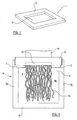
- Figure 1 shows a first embodiment of a compacting device 1, which comprises a plate 2 which is substantially rectangular in shape.
- the plate is provided with an aperture 3, which is positioned approximately centrally in the plate, and is also substantially rectangular in shape.
- the aperture 3 has a size of approximately 225mm by 50mm.
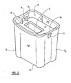
- Figure 2 shows the compacting plate 1 of Figure 1 , fixed in an open end 4 of a receptacle which comprises a bin 5, at a depth d beneath the open end.
- the bin comprises a bottom 6 and four sides 7a, 7b, 7c and 7d.
- a first end 8 of the plate 2 of the compacting device is fixed to a first side 7a of the bin 5, by hinges 9.
- the hinges may comprise living hinges.
- a second, opposite end 10 of the plate 2 of the compacting device is held by a catch 11 against a second side 7c of the bin 5.
- the catch is releasable, and the plate 2 pivots between a closed position as shown in the figure, and an open position in which the bin may be emptied.
- the plate 2 of the compacting device has a size which is comparable to the cross sectional area of the open end of the bin 5, i.e. the plate 2 substantially fills and closes off the open end 4 of the bin 5.
- FIG 3 shows the compacting device 1 and bin 5 of Figure 2 , in use with a shredder 12.
- the shredder is positioned on the open end 4 of the bin 5, and partially extends within the bin as shown.
- the shredder 12 is not fixed to the bin 5, but rests on the open end of the bin.
- the compacting device 1 is positioned relative to the shredder 12 such that the distance between them is as small as possible.
- the compacting device 1 is also positioned relative to the shredder 12 such that the aperture 3 of the device is substantially aligned with an outlet aperture 13 of the shredder 12.
- the shredder 12 receives paper 14, and shreds this into shredded material which comprises strips of paper. These are output from the outlet aperture 13 of the shredder 12, and are passed through the aperture 3 of the plate 2 of the compacting device 1, and are collected in the bin 5.
- the shredded paper forms an approximately pyramidal mass of material 15 beneath the aperture 3. As the bin 5, starts to fill with shredded paper, eventually this starts to press against the underside of the plate 2. As the plate 2 is fixed relative to the bin 5, the shredded paper is compacted by compression thereof between the bottom and sides of the bin 5 and the plate 2 as collection of the shredded paper progresses.
- the shredder 12 When it is desired to empty the bin 5, the shredder 12 is lifted away from the open end of the bin.
- the plate 2 of the compaction device 1 will remain in the closed position, and will act to hold at least a substantial part of the shredded paper within it.
- the bin 5 can then be placed in a refuse sack, and the catch 11 released, allowing the plate 2 to pivot to an open position, and the shredded paper to be released into the sack.
- both sides 8 and 10 of the plate 2 can be rigidly fixed to the sides 7a and 7c of the bin 5.
- the bin 5 may then be emptied through one of the sides or through the bottom thereof.
- An alternative embodiment of the compacting device of the invention comprises a plate having first and second substantially parallel portions which are separated by a sloped portion. An aperture is provided in the sloped portion.
- This compacting device is utilised in the same way as that described above, and has approximately the same compacting action as the device described above. This type of compacting device is particularly useful when the device is used with a receptacle which is removed from a shredder to be emptied by pulling it along the length of the shredder. Shredded material is less likely to impede removal of the receptacle.
Landscapes
- Engineering & Computer Science (AREA)
- Food Science & Technology (AREA)
- Mechanical Engineering (AREA)
- Crushing And Pulverization Processes (AREA)
Description
- The invention relates to the field of shredders such as those which may be used to shred, for example, paper, cardboard and the like, and also to compacting devices for use in compacting paper etc. which has been shredded in that way.
- Conventionally, shredders, such as, bin-top or cabinet paper shredders are each used in conjunction with a bin to collect the paper once it has been shredded. During the process of shredding and then collecting, the shredded paper is compacted within the bin to, generally, only a limited extent. The bin can therefore quickly become substantially full of mostly non-compacted paper. In bin-top shredders, further collection of shredded paper in the bin will tend to lift the head of the shredder off the bin. In cabinet shredders, further collection of shredded paper in the bin tends to cause activation of a 'bin full' indicator or the bin to 'pop out' away from the shredder. In either case, shredding is usually ceased and the bin emptied. If the shredded paper where to be further compacted, the bin could be emptied less often. Further compaction is often achieved by compression of the paper by hand, but this requires manual intervention, which can be undesirable.
-
DE19617487 discloses a catchment container for emptying after release of a securing device which is held on a rotary axis in the upper part and is pivotable downwards to such an extent that the cut material can slide out of the catchment container into a collection container. The catchment container is lockable on the upper part by means of a securing device in the operating position and by means of a second securing device in a switch-off position automatically releasable when the catchment container is filled with cut material. On the upper part a tab is arranged, which comes into engagement with one of the two securing devices of the catchment container in the operating position or in the switch-off position. - According to the present invention, there is provided a shredding device comprising a receptacle for the collection of shredded material output from a shredder comprising a bin a shredder including an outlet aperture resting on an open end of the bin characterised in that a compacting device comprising a plate provided with an aperture, wherein the plate is attached within the bin at a depth beneath an open end thereof; and the shredder partially extends within the bin such that the aperture is substantially aligned with the outlet aperture and the plate is positioned relative to the shredder such that the distance between them is as small as possible, so that shredded material output from the shredder through the outlet aperture passes through the aperture of the plate and is collected in the bin and as collection of the shredded material within the bin progresses, the plate acts to compact the material.
- Preferably, the shredded material is compacted by by compression of the material between bottom and sides of the receptacle and the plate as collection of the material progresses.
- Conveniently, the compaction of the material forms and maintains a substantially pyramidal mass of material beneath the aperture, against which further material output from the shredder is compressed.
- Advantageously, the plate of the compacting device has a size which is comparable to the cross sectional area of the open end of the receptacle.
- Preferably, a first side of the compacting device is hingeably attached to a first side of the receptacle, and a second side of the compacting device is releasably attached to a second side of the receptacle.
- Conveniently, a first side and a second side of the compacting device are rigidly fixed to first and second sides of the receptacle.
- Advantageously, the plate of the compacting device comprises a sloped portion between two substantially parallel portions, and the aperture may be provided in the sloped portion.
- An embodiment of the invention will now be described by way of example only, with reference to the accompanying drawings, in which:
-
Figure 1 is a perspective schematic representation of a compacting device, according to the invention; -
Figure 2 is perspective schematic representation of the compacting device ofFigure 1 fixed within an open end of a receptacle, and -
Figure 3 is cross sectional schematic representation of the compacting device and receptacle ofFigure 2 with a shredder. -
Figure 1 shows a first embodiment of a compacting device 1, which comprises aplate 2 which is substantially rectangular in shape. The plate is provided with anaperture 3, which is positioned approximately centrally in the plate, and is also substantially rectangular in shape. Theaperture 3 has a size of approximately 225mm by 50mm. -
Figure 2 shows the compacting plate 1 ofFigure 1 , fixed in anopen end 4 of a receptacle which comprises abin 5, at a depth d beneath the open end. The bin comprises abottom 6 and foursides first end 8 of theplate 2 of the compacting device is fixed to afirst side 7a of thebin 5, by hinges 9. The hinges may comprise living hinges. A second,opposite end 10 of theplate 2 of the compacting device is held by acatch 11 against asecond side 7c of thebin 5. The catch is releasable, and theplate 2 pivots between a closed position as shown in the figure, and an open position in which the bin may be emptied. Theplate 2 of the compacting device has a size which is comparable to the cross sectional area of the open end of thebin 5, i.e. theplate 2 substantially fills and closes off theopen end 4 of thebin 5. -
Figure 3 shows the compacting device 1 andbin 5 ofFigure 2 , in use with ashredder 12. The shredder is positioned on theopen end 4 of thebin 5, and partially extends within the bin as shown. Theshredder 12 is not fixed to thebin 5, but rests on the open end of the bin. The compacting device 1 is positioned relative to theshredder 12 such that the distance between them is as small as possible. The compacting device 1 is also positioned relative to theshredder 12 such that theaperture 3 of the device is substantially aligned with anoutlet aperture 13 of theshredder 12. - The
shredder 12 receivespaper 14, and shreds this into shredded material which comprises strips of paper. These are output from theoutlet aperture 13 of theshredder 12, and are passed through theaperture 3 of theplate 2 of the compacting device 1, and are collected in thebin 5. The shredded paper forms an approximately pyramidal mass ofmaterial 15 beneath theaperture 3. As thebin 5, starts to fill with shredded paper, eventually this starts to press against the underside of theplate 2. As theplate 2 is fixed relative to thebin 5, the shredded paper is compacted by compression thereof between the bottom and sides of thebin 5 and theplate 2 as collection of the shredded paper progresses. In addition, as more and more paper is shredded, this is compressed against a top portion of the pyramidal mass of shreddedpaper 15 which is formed beneath theaperture 3, and thus the shredded paper is also compacted. Thus more shredded paper may be collected in thebin 5, than may be collected in a comparable bin from a comparable shredder without use of the compacting plate. - When it is desired to empty the
bin 5, theshredder 12 is lifted away from the open end of the bin. Theplate 2 of the compaction device 1 will remain in the closed position, and will act to hold at least a substantial part of the shredded paper within it. Thebin 5 can then be placed in a refuse sack, and thecatch 11 released, allowing theplate 2 to pivot to an open position, and the shredded paper to be released into the sack. - It will be appreciated that both
sides plate 2 can be rigidly fixed to thesides bin 5. Thebin 5 may then be emptied through one of the sides or through the bottom thereof. - The above describes use of the compacting device with a bin-mounted shredder. However, it will be appreciated that this compacting device can also be used in a bin which is positioned below a cabinet-type shredder.
- An alternative embodiment of the compacting device of the invention comprises a plate having first and second substantially parallel portions which are separated by a sloped portion. An aperture is provided in the sloped portion. This compacting device is utilised in the same way as that described above, and has approximately the same compacting action as the device described above. This type of compacting device is particularly useful when the device is used with a receptacle which is removed from a shredder to be emptied by pulling it along the length of the shredder. Shredded material is less likely to impede removal of the receptacle.
- When used in this specification and claims, the terms "comprises" and "comprising" and variations thereof mean that the specified features, steps or integers are included. The terms are not to be interpreted to exclude the presence of other features, steps or components.
- The features disclosed in the foregoing description, or the following claims, or the accompanying drawings, expressed in their specific forms or in terms of a means for performing the disclosed function, or a method or process for attaining the disclosed result, as appropriate, may, separately, or in any combination of such features, be utilised for realising the invention in diverse forms thereof.
Claims (7)
- A shredding device comprising:a receptacle (5) for the collection of shredded material (15) output from a shredder (12) comprising a bin (5);a shredder (12) including an outlet aperture (13) resting on an open end of the bin (5); characterised in thata compacting device (1) comprising a plate (2) provided with an aperture (3), wherein the plate (2) is attached within the bin (5) at a depth beneath an open end (4) thereof; andthe shredder (12) partially extends within the bin (5) such that the aperture (3) is substantially aligned with the outlet aperture (13) and the plate (2) is positioned relative to the shredder (12) such that the distance between them is as small as possible, so that shredded material (15) output from the shredder (12) through the outlet aperture (13) passes through the aperture (3) of the plate (2) and is collected in the bin (5); andas collection of the shredded material (15) within the bin progresses, the plate (2) acts to compact the material (15).
- A shredding device according to claim 1 wherein the shredded material (15) is compacted by by compression of the material (15) between bottom (6) and sides (7a to 7d) of the receptacle (5) and the plate (2) as collection of the material (15) progresses.
- A shredding device according to claim 1 or claim 2 wherein the compaction of the material (15) forms and maintains a substantially pyramidal mass of material (15) beneath the aperture (3), against which further material (15) output from the shredder (12) is compressed.
- A shredding device according to any preceding claim in which the plate (2) of the compacting device (1) has a size which is comparable to the cross sectional area of the open end (4) of the receptacle (5).
- A shredding device according to any preceding claim in which a first side (8) of the compacting device (1) is hingeably attached (9) to a first side of the receptacle (5), and a second side (10) of the compacting device (1) is releasably attached to a second side (10) of the receptacle (5).
- A shredding device according to any of claims 1 to 7 in which a first side (8) and a second side (10) of the compacting device (1) are rigidly fixed to first and second sides of the receptacle.
- A shredding device according to any preceding claim in which the plate (3) of the compacting device (1) comprises a sloped portion between two substantially parallel portions, and the aperture (3) may be provided in the sloped portion.
Applications Claiming Priority (1)
| Application Number | Priority Date | Filing Date | Title |
|---|---|---|---|
| GB0427091A GB2420994B (en) | 2004-12-10 | 2004-12-10 | Compacting device |
Publications (3)
| Publication Number | Publication Date |
|---|---|
| EP1669187A2 EP1669187A2 (en) | 2006-06-14 |
| EP1669187A3 EP1669187A3 (en) | 2006-11-15 |
| EP1669187B1 true EP1669187B1 (en) | 2014-02-12 |
Family
ID=34073508
Family Applications (1)
| Application Number | Title | Priority Date | Filing Date |
|---|---|---|---|
| EP05027126.1A Expired - Lifetime EP1669187B1 (en) | 2004-12-10 | 2005-12-12 | Shredders and compacting devices therefor |
Country Status (3)
| Country | Link |
|---|---|
| US (1) | US20060151647A1 (en) |
| EP (1) | EP1669187B1 (en) |
| GB (1) | GB2420994B (en) |
Families Citing this family (4)
| Publication number | Priority date | Publication date | Assignee | Title |
|---|---|---|---|---|
| GB2427838A (en) * | 2005-07-01 | 2007-01-10 | Acco Uk Ltd | A shredder including a compactor plate that forms part of a waste bag support mechanism |
| GB2450551B (en) * | 2007-06-29 | 2012-01-04 | Acco Uk Ltd | A shredding machine |
| US20100050887A1 (en) * | 2008-08-29 | 2010-03-04 | Freda Robert B | Self-Contained Roll-off Shredding Compactor System |
| BR202017001034Y1 (en) * | 2017-01-18 | 2023-03-21 | Indústria E Comércio De Molduras Santa Luzia Ltda | CONSTRUCTIVE ARRANGEMENT APPLIED IN A MACHINE FOR GRINDING AND COMPACTION OF RECYCLABLE POLYMERIC MATERIAL |
Citations (1)
| Publication number | Priority date | Publication date | Assignee | Title |
|---|---|---|---|---|
| DE19618478C1 (en) * | 1996-05-08 | 1997-09-25 | Geha Werke Gmbh | Printed material destructor with upper part containing material feed shaft and cutting mechanism |
Family Cites Families (14)
| Publication number | Priority date | Publication date | Assignee | Title |
|---|---|---|---|---|
| US929960A (en) * | 1909-02-02 | 1909-08-03 | Abbot Augustus Low | Waste-paper receptacle. |
| US3754498A (en) * | 1971-12-17 | 1973-08-28 | R Gil | Apparatus for shredding and baling paper |
| DE2214800C3 (en) * | 1972-03-25 | 1981-05-14 | Eba-Maschinenfabrik Adolf Ehinger Kg, 7460 Balingen | Shredding device with a cutting or shredding mechanism |
| CA964632A (en) * | 1972-05-30 | 1975-03-18 | Quinto De Filippi | Refuse disposal apparatus |
| DE3835450C2 (en) * | 1988-10-18 | 1995-09-14 | Hsm Pressen Gmbh | Protective cover for a document shredder combined with a baler |
| US4991500A (en) * | 1989-06-08 | 1991-02-12 | Knapp James S | Refuse compactor device |
| CA2043006C (en) * | 1991-05-22 | 1996-03-19 | James Tansley Knowler | Shredder/compactor assembly for recycling waste material |
| DE19539792C2 (en) * | 1995-10-26 | 1998-01-29 | Geha Werke Gmbh | Document shredder |
| DE29622139U1 (en) * | 1996-12-20 | 1997-03-20 | Wilhelm Dahle Büro-Technik GmbH & Co KG, 96450 Coburg | Holding device for a paper shredder |
| AUPP111797A0 (en) * | 1997-12-24 | 1998-01-22 | Gill, Walter | Shredder and baler apparatus |
| JPH11276260A (en) * | 1998-03-31 | 1999-10-12 | Silver Seiko Ltd | Office desk with shredder |
| US5988542A (en) * | 1998-05-18 | 1999-11-23 | General Binding Corporation | Document shredding devices |
| EP1545807A2 (en) * | 2002-07-31 | 2005-06-29 | David M. Stravitz | Waste disposal device |
| US7025293B2 (en) * | 2004-04-21 | 2006-04-11 | Fellows Inc. | Shredder with pivoting housing for the shredder mechanism |
-
2004
- 2004-12-10 GB GB0427091A patent/GB2420994B/en not_active Expired - Lifetime
-
2005
- 2005-12-08 US US11/297,804 patent/US20060151647A1/en not_active Abandoned
- 2005-12-12 EP EP05027126.1A patent/EP1669187B1/en not_active Expired - Lifetime
Patent Citations (1)
| Publication number | Priority date | Publication date | Assignee | Title |
|---|---|---|---|---|
| DE19618478C1 (en) * | 1996-05-08 | 1997-09-25 | Geha Werke Gmbh | Printed material destructor with upper part containing material feed shaft and cutting mechanism |
Also Published As
| Publication number | Publication date |
|---|---|
| GB0427091D0 (en) | 2005-01-12 |
| US20060151647A1 (en) | 2006-07-13 |
| EP1669187A3 (en) | 2006-11-15 |
| EP1669187A2 (en) | 2006-06-14 |
| GB2420994A (en) | 2006-06-14 |
| GB2420994B (en) | 2009-03-11 |
Similar Documents
| Publication | Publication Date | Title |
|---|---|---|
| US7762486B2 (en) | Shredder | |
| EP1741490B1 (en) | Shredder with compacting plate supporting waste bag | |
| EP2011745B1 (en) | Waste collecting device and method for using such a device | |
| EP1669187A2 (en) | Shredders and compacting devices therefor | |
| US20110139914A1 (en) | Shredder | |
| US7434507B1 (en) | System and trash receptacle for collecting and compacting trash | |
| DE102005025965A1 (en) | Recyclable material, e.g. beverage package, collecting system, e.g. for use in shop area, has mobile enclosure in thermo and sound insulation constructive form arranged around system, where system is modularly assembled | |
| EP0941948A1 (en) | Assembly for collecting and compressing waste and method therefor | |
| KR100983527B1 (en) | Garbage Compressor with Bonding Function | |
| JP4129573B2 (en) | Shredder shredder leveling compressor | |
| JP3118647B2 (en) | Document shredder with shredder spreading and compression device, and its diffusion and compression device | |
| GB2511933A (en) | Paper shredder with output deflector | |
| JPS598751Y2 (en) | Compression device with document shredding mechanism | |
| KR20220116726A (en) | One touch food garbage treatment apparatus | |
| JP3650868B2 (en) | Guillotine-type crusher for crushing compacted waste | |
| KR102924778B1 (en) | Recyclables wastes crusher | |
| KR950009729Y1 (en) | Refuse receptacle with press | |
| JPH11114539A (en) | Garbage separation method and apparatus | |
| KR102580525B1 (en) | Container for collecting waste | |
| JPH0741102A (en) | Trash compression vessel with empty-can crusher | |
| JP2928939B2 (en) | Document shredder with shredder scattering and compression device and its diffusion compression device | |
| SE539299C2 (en) | Waste compactor for handling different types of waste | |
| CN218432137U (en) | Waterproofing membrane cutting device's garbage collection structure | |
| GB2613589A (en) | Combined shredding and compressing system | |
| KR20220001369U (en) | Paper Shredder Secondary Collection Box |
Legal Events
| Date | Code | Title | Description |
|---|---|---|---|
| PUAI | Public reference made under article 153(3) epc to a published international application that has entered the european phase |
Free format text: ORIGINAL CODE: 0009012 |
|
| AK | Designated contracting states |
Kind code of ref document: A2 Designated state(s): AT BE BG CH CY CZ DE DK EE ES FI FR GB GR HU IE IS IT LI LT LU LV MC NL PL PT RO SE SI SK TR |
|
| AX | Request for extension of the european patent |
Extension state: AL BA HR MK YU |
|
| PUAL | Search report despatched |
Free format text: ORIGINAL CODE: 0009013 |
|
| AK | Designated contracting states |
Kind code of ref document: A3 Designated state(s): AT BE BG CH CY CZ DE DK EE ES FI FR GB GR HU IE IS IT LI LT LU LV MC NL PL PT RO SE SI SK TR |
|
| AX | Request for extension of the european patent |
Extension state: AL BA HR MK YU |
|
| 17P | Request for examination filed |
Effective date: 20070328 |
|
| AKX | Designation fees paid |
Designated state(s): AT BE BG CH CY CZ DE DK EE ES FI FR GB GR HU IE IS IT LI LT LU LV MC NL PL PT RO SE SI SK TR |
|
| 17Q | First examination report despatched |
Effective date: 20121214 |
|
| GRAP | Despatch of communication of intention to grant a patent |
Free format text: ORIGINAL CODE: EPIDOSNIGR1 |
|
| INTG | Intention to grant announced |
Effective date: 20130822 |
|
| GRAS | Grant fee paid |
Free format text: ORIGINAL CODE: EPIDOSNIGR3 |
|
| GRAA | (expected) grant |
Free format text: ORIGINAL CODE: 0009210 |
|
| AK | Designated contracting states |
Kind code of ref document: B1 Designated state(s): AT BE BG CH CY CZ DE DK EE ES FI FR GB GR HU IE IS IT LI LT LU LV MC NL PL PT RO SE SI SK TR |
|
| REG | Reference to a national code |
Ref country code: GB Ref legal event code: FG4D |
|
| REG | Reference to a national code |
Ref country code: CH Ref legal event code: EP |
|
| REG | Reference to a national code |
Ref country code: AT Ref legal event code: REF Ref document number: 651947 Country of ref document: AT Kind code of ref document: T Effective date: 20140215 |
|
| REG | Reference to a national code |
Ref country code: DE Ref legal event code: R096 Ref document number: 602005042651 Country of ref document: DE Effective date: 20140320 |
|
| REG | Reference to a national code |
Ref country code: IE Ref legal event code: FG4D |
|
| REG | Reference to a national code |
Ref country code: NL Ref legal event code: VDEP Effective date: 20140212 |
|
| REG | Reference to a national code |
Ref country code: AT Ref legal event code: MK05 Ref document number: 651947 Country of ref document: AT Kind code of ref document: T Effective date: 20140212 |
|
| REG | Reference to a national code |
Ref country code: LT Ref legal event code: MG4D |
|
| PG25 | Lapsed in a contracting state [announced via postgrant information from national office to epo] |
Ref country code: IS Free format text: LAPSE BECAUSE OF FAILURE TO SUBMIT A TRANSLATION OF THE DESCRIPTION OR TO PAY THE FEE WITHIN THE PRESCRIBED TIME-LIMIT Effective date: 20140612 Ref country code: LT Free format text: LAPSE BECAUSE OF FAILURE TO SUBMIT A TRANSLATION OF THE DESCRIPTION OR TO PAY THE FEE WITHIN THE PRESCRIBED TIME-LIMIT Effective date: 20140212 |
|
| PG25 | Lapsed in a contracting state [announced via postgrant information from national office to epo] |
Ref country code: CY Free format text: LAPSE BECAUSE OF FAILURE TO SUBMIT A TRANSLATION OF THE DESCRIPTION OR TO PAY THE FEE WITHIN THE PRESCRIBED TIME-LIMIT Effective date: 20140212 Ref country code: SE Free format text: LAPSE BECAUSE OF FAILURE TO SUBMIT A TRANSLATION OF THE DESCRIPTION OR TO PAY THE FEE WITHIN THE PRESCRIBED TIME-LIMIT Effective date: 20140212 Ref country code: AT Free format text: LAPSE BECAUSE OF FAILURE TO SUBMIT A TRANSLATION OF THE DESCRIPTION OR TO PAY THE FEE WITHIN THE PRESCRIBED TIME-LIMIT Effective date: 20140212 Ref country code: ES Free format text: LAPSE BECAUSE OF FAILURE TO SUBMIT A TRANSLATION OF THE DESCRIPTION OR TO PAY THE FEE WITHIN THE PRESCRIBED TIME-LIMIT Effective date: 20140212 Ref country code: FI Free format text: LAPSE BECAUSE OF FAILURE TO SUBMIT A TRANSLATION OF THE DESCRIPTION OR TO PAY THE FEE WITHIN THE PRESCRIBED TIME-LIMIT Effective date: 20140212 Ref country code: NL Free format text: LAPSE BECAUSE OF FAILURE TO SUBMIT A TRANSLATION OF THE DESCRIPTION OR TO PAY THE FEE WITHIN THE PRESCRIBED TIME-LIMIT Effective date: 20140212 |
|
| PG25 | Lapsed in a contracting state [announced via postgrant information from national office to epo] |
Ref country code: LV Free format text: LAPSE BECAUSE OF FAILURE TO SUBMIT A TRANSLATION OF THE DESCRIPTION OR TO PAY THE FEE WITHIN THE PRESCRIBED TIME-LIMIT Effective date: 20140212 Ref country code: BE Free format text: LAPSE BECAUSE OF FAILURE TO SUBMIT A TRANSLATION OF THE DESCRIPTION OR TO PAY THE FEE WITHIN THE PRESCRIBED TIME-LIMIT Effective date: 20140212 |
|
| PG25 | Lapsed in a contracting state [announced via postgrant information from national office to epo] |
Ref country code: RO Free format text: LAPSE BECAUSE OF FAILURE TO SUBMIT A TRANSLATION OF THE DESCRIPTION OR TO PAY THE FEE WITHIN THE PRESCRIBED TIME-LIMIT Effective date: 20140212 Ref country code: EE Free format text: LAPSE BECAUSE OF FAILURE TO SUBMIT A TRANSLATION OF THE DESCRIPTION OR TO PAY THE FEE WITHIN THE PRESCRIBED TIME-LIMIT Effective date: 20140212 Ref country code: DK Free format text: LAPSE BECAUSE OF FAILURE TO SUBMIT A TRANSLATION OF THE DESCRIPTION OR TO PAY THE FEE WITHIN THE PRESCRIBED TIME-LIMIT Effective date: 20140212 Ref country code: CZ Free format text: LAPSE BECAUSE OF FAILURE TO SUBMIT A TRANSLATION OF THE DESCRIPTION OR TO PAY THE FEE WITHIN THE PRESCRIBED TIME-LIMIT Effective date: 20140212 |
|
| REG | Reference to a national code |
Ref country code: DE Ref legal event code: R097 Ref document number: 602005042651 Country of ref document: DE |
|
| PG25 | Lapsed in a contracting state [announced via postgrant information from national office to epo] |
Ref country code: PL Free format text: LAPSE BECAUSE OF FAILURE TO SUBMIT A TRANSLATION OF THE DESCRIPTION OR TO PAY THE FEE WITHIN THE PRESCRIBED TIME-LIMIT Effective date: 20140212 Ref country code: SK Free format text: LAPSE BECAUSE OF FAILURE TO SUBMIT A TRANSLATION OF THE DESCRIPTION OR TO PAY THE FEE WITHIN THE PRESCRIBED TIME-LIMIT Effective date: 20140212 |
|
| PLBE | No opposition filed within time limit |
Free format text: ORIGINAL CODE: 0009261 |
|
| STAA | Information on the status of an ep patent application or granted ep patent |
Free format text: STATUS: NO OPPOSITION FILED WITHIN TIME LIMIT |
|
| 26N | No opposition filed |
Effective date: 20141113 |
|
| REG | Reference to a national code |
Ref country code: DE Ref legal event code: R097 Ref document number: 602005042651 Country of ref document: DE Effective date: 20141113 |
|
| PG25 | Lapsed in a contracting state [announced via postgrant information from national office to epo] |
Ref country code: IT Free format text: LAPSE BECAUSE OF FAILURE TO SUBMIT A TRANSLATION OF THE DESCRIPTION OR TO PAY THE FEE WITHIN THE PRESCRIBED TIME-LIMIT Effective date: 20140212 |
|
| PG25 | Lapsed in a contracting state [announced via postgrant information from national office to epo] |
Ref country code: SI Free format text: LAPSE BECAUSE OF FAILURE TO SUBMIT A TRANSLATION OF THE DESCRIPTION OR TO PAY THE FEE WITHIN THE PRESCRIBED TIME-LIMIT Effective date: 20140212 |
|
| PG25 | Lapsed in a contracting state [announced via postgrant information from national office to epo] |
Ref country code: LU Free format text: LAPSE BECAUSE OF FAILURE TO SUBMIT A TRANSLATION OF THE DESCRIPTION OR TO PAY THE FEE WITHIN THE PRESCRIBED TIME-LIMIT Effective date: 20141212 |
|
| PGFP | Annual fee paid to national office [announced via postgrant information from national office to epo] |
Ref country code: GB Payment date: 20150615 Year of fee payment: 10 |
|
| REG | Reference to a national code |
Ref country code: CH Ref legal event code: PL |
|
| REG | Reference to a national code |
Ref country code: IE Ref legal event code: MM4A |
|
| REG | Reference to a national code |
Ref country code: FR Ref legal event code: ST Effective date: 20150831 |
|
| PG25 | Lapsed in a contracting state [announced via postgrant information from national office to epo] |
Ref country code: LI Free format text: LAPSE BECAUSE OF NON-PAYMENT OF DUE FEES Effective date: 20141231 Ref country code: IE Free format text: LAPSE BECAUSE OF NON-PAYMENT OF DUE FEES Effective date: 20141212 Ref country code: CH Free format text: LAPSE BECAUSE OF NON-PAYMENT OF DUE FEES Effective date: 20141231 |
|
| PG25 | Lapsed in a contracting state [announced via postgrant information from national office to epo] |
Ref country code: FR Free format text: LAPSE BECAUSE OF NON-PAYMENT OF DUE FEES Effective date: 20141231 |
|
| PG25 | Lapsed in a contracting state [announced via postgrant information from national office to epo] |
Ref country code: MC Free format text: LAPSE BECAUSE OF FAILURE TO SUBMIT A TRANSLATION OF THE DESCRIPTION OR TO PAY THE FEE WITHIN THE PRESCRIBED TIME-LIMIT Effective date: 20140212 Ref country code: BG Free format text: LAPSE BECAUSE OF FAILURE TO SUBMIT A TRANSLATION OF THE DESCRIPTION OR TO PAY THE FEE WITHIN THE PRESCRIBED TIME-LIMIT Effective date: 20140212 |
|
| PG25 | Lapsed in a contracting state [announced via postgrant information from national office to epo] |
Ref country code: GR Free format text: LAPSE BECAUSE OF FAILURE TO SUBMIT A TRANSLATION OF THE DESCRIPTION OR TO PAY THE FEE WITHIN THE PRESCRIBED TIME-LIMIT Effective date: 20140513 Ref country code: PT Free format text: LAPSE BECAUSE OF FAILURE TO SUBMIT A TRANSLATION OF THE DESCRIPTION OR TO PAY THE FEE WITHIN THE PRESCRIBED TIME-LIMIT Effective date: 20140212 |
|
| PG25 | Lapsed in a contracting state [announced via postgrant information from national office to epo] |
Ref country code: TR Free format text: LAPSE BECAUSE OF FAILURE TO SUBMIT A TRANSLATION OF THE DESCRIPTION OR TO PAY THE FEE WITHIN THE PRESCRIBED TIME-LIMIT Effective date: 20140212 Ref country code: HU Free format text: LAPSE BECAUSE OF FAILURE TO SUBMIT A TRANSLATION OF THE DESCRIPTION OR TO PAY THE FEE WITHIN THE PRESCRIBED TIME-LIMIT; INVALID AB INITIO Effective date: 20051212 |
|
| GBPC | Gb: european patent ceased through non-payment of renewal fee |
Effective date: 20151212 |
|
| PG25 | Lapsed in a contracting state [announced via postgrant information from national office to epo] |
Ref country code: GB Free format text: LAPSE BECAUSE OF NON-PAYMENT OF DUE FEES Effective date: 20151212 |
|
| PGFP | Annual fee paid to national office [announced via postgrant information from national office to epo] |
Ref country code: DE Payment date: 20241121 Year of fee payment: 20 |
|
| REG | Reference to a national code |
Ref country code: DE Ref legal event code: R071 Ref document number: 602005042651 Country of ref document: DE |