EP1668225B1 - Turbocompresseur a geometrie variable - Google Patents
Turbocompresseur a geometrie variable Download PDFInfo
- Publication number
- EP1668225B1 EP1668225B1 EP04784953.4A EP04784953A EP1668225B1 EP 1668225 B1 EP1668225 B1 EP 1668225B1 EP 04784953 A EP04784953 A EP 04784953A EP 1668225 B1 EP1668225 B1 EP 1668225B1
- Authority
- EP
- European Patent Office
- Prior art keywords
- axial surface
- vane
- axial
- cored
- assembly
- Prior art date
- Legal status (The legal status is an assumption and is not a legal conclusion. Google has not performed a legal analysis and makes no representation as to the accuracy of the status listed.)
- Active
Links
- 239000007787 solid Substances 0.000 claims description 54
- 238000010276 construction Methods 0.000 claims description 9
- 239000002131 composite material Substances 0.000 claims description 7
- 230000000694 effects Effects 0.000 description 5
- 238000002485 combustion reaction Methods 0.000 description 3
- 230000009471 action Effects 0.000 description 2
- 230000000712 assembly Effects 0.000 description 2
- 238000000429 assembly Methods 0.000 description 2
- 230000009286 beneficial effect Effects 0.000 description 2
- 238000013461 design Methods 0.000 description 2
- 238000000034 method Methods 0.000 description 2
- 238000012986 modification Methods 0.000 description 2
- 230000004048 modification Effects 0.000 description 2
- 230000002411 adverse Effects 0.000 description 1
- 238000013459 approach Methods 0.000 description 1
- 238000005266 casting Methods 0.000 description 1
- 230000001419 dependent effect Effects 0.000 description 1
- 238000011161 development Methods 0.000 description 1
- 230000018109 developmental process Effects 0.000 description 1
- 239000000446 fuel Substances 0.000 description 1
- 238000001746 injection moulding Methods 0.000 description 1
- 238000003754 machining Methods 0.000 description 1
- 239000000463 material Substances 0.000 description 1
- 230000007246 mechanism Effects 0.000 description 1
- 239000002184 metal Substances 0.000 description 1
- 239000000203 mixture Substances 0.000 description 1
- 238000000465 moulding Methods 0.000 description 1
- 230000008569 process Effects 0.000 description 1
- 230000004044 response Effects 0.000 description 1
- 238000009987 spinning Methods 0.000 description 1
- 238000006467 substitution reaction Methods 0.000 description 1
Images


Classifications
-
- F—MECHANICAL ENGINEERING; LIGHTING; HEATING; WEAPONS; BLASTING
- F01—MACHINES OR ENGINES IN GENERAL; ENGINE PLANTS IN GENERAL; STEAM ENGINES
- F01D—NON-POSITIVE DISPLACEMENT MACHINES OR ENGINES, e.g. STEAM TURBINES
- F01D11/00—Preventing or minimising internal leakage of working-fluid, e.g. between stages
- F01D11/005—Sealing means between non relatively rotating elements
-
- F—MECHANICAL ENGINEERING; LIGHTING; HEATING; WEAPONS; BLASTING
- F01—MACHINES OR ENGINES IN GENERAL; ENGINE PLANTS IN GENERAL; STEAM ENGINES
- F01D—NON-POSITIVE DISPLACEMENT MACHINES OR ENGINES, e.g. STEAM TURBINES
- F01D17/00—Regulating or controlling by varying flow
- F01D17/10—Final actuators
- F01D17/12—Final actuators arranged in stator parts
- F01D17/14—Final actuators arranged in stator parts varying effective cross-sectional area of nozzles or guide conduits
- F01D17/16—Final actuators arranged in stator parts varying effective cross-sectional area of nozzles or guide conduits by means of nozzle vanes
- F01D17/165—Final actuators arranged in stator parts varying effective cross-sectional area of nozzles or guide conduits by means of nozzle vanes for radial flow, i.e. the vanes turning around axes which are essentially parallel to the rotor centre line
-
- F—MECHANICAL ENGINEERING; LIGHTING; HEATING; WEAPONS; BLASTING
- F01—MACHINES OR ENGINES IN GENERAL; ENGINE PLANTS IN GENERAL; STEAM ENGINES
- F01D—NON-POSITIVE DISPLACEMENT MACHINES OR ENGINES, e.g. STEAM TURBINES
- F01D5/00—Blades; Blade-carrying members; Heating, heat-insulating, cooling or antivibration means on the blades or the members
- F01D5/12—Blades
- F01D5/14—Form or construction
- F01D5/141—Shape, i.e. outer, aerodynamic form
-
- F—MECHANICAL ENGINEERING; LIGHTING; HEATING; WEAPONS; BLASTING
- F02—COMBUSTION ENGINES; HOT-GAS OR COMBUSTION-PRODUCT ENGINE PLANTS
- F02C—GAS-TURBINE PLANTS; AIR INTAKES FOR JET-PROPULSION PLANTS; CONTROLLING FUEL SUPPLY IN AIR-BREATHING JET-PROPULSION PLANTS
- F02C6/00—Plural gas-turbine plants; Combinations of gas-turbine plants with other apparatus; Adaptations of gas- turbine plants for special use
- F02C6/04—Gas-turbine plants providing heated or pressurised working fluid for other apparatus, e.g. without mechanical power output
- F02C6/10—Gas-turbine plants providing heated or pressurised working fluid for other apparatus, e.g. without mechanical power output supplying working fluid to a user, e.g. a chemical process, which returns working fluid to a turbine of the plant
- F02C6/12—Turbochargers, i.e. plants for augmenting mechanical power output of internal-combustion piston engines by increase of charge pressure
-
- F—MECHANICAL ENGINEERING; LIGHTING; HEATING; WEAPONS; BLASTING
- F02—COMBUSTION ENGINES; HOT-GAS OR COMBUSTION-PRODUCT ENGINE PLANTS
- F02B—INTERNAL-COMBUSTION PISTON ENGINES; COMBUSTION ENGINES IN GENERAL
- F02B37/00—Engines characterised by provision of pumps driven at least for part of the time by exhaust
- F02B37/12—Control of the pumps
- F02B37/24—Control of the pumps by using pumps or turbines with adjustable guide vanes
-
- F—MECHANICAL ENGINEERING; LIGHTING; HEATING; WEAPONS; BLASTING
- F05—INDEXING SCHEMES RELATING TO ENGINES OR PUMPS IN VARIOUS SUBCLASSES OF CLASSES F01-F04
- F05D—INDEXING SCHEME FOR ASPECTS RELATING TO NON-POSITIVE-DISPLACEMENT MACHINES OR ENGINES, GAS-TURBINES OR JET-PROPULSION PLANTS
- F05D2220/00—Application
- F05D2220/40—Application in turbochargers
-
- F—MECHANICAL ENGINEERING; LIGHTING; HEATING; WEAPONS; BLASTING
- F05—INDEXING SCHEMES RELATING TO ENGINES OR PUMPS IN VARIOUS SUBCLASSES OF CLASSES F01-F04
- F05D—INDEXING SCHEME FOR ASPECTS RELATING TO NON-POSITIVE-DISPLACEMENT MACHINES OR ENGINES, GAS-TURBINES OR JET-PROPULSION PLANTS
- F05D2240/00—Components
- F05D2240/10—Stators
- F05D2240/12—Fluid guiding means, e.g. vanes
-
- F—MECHANICAL ENGINEERING; LIGHTING; HEATING; WEAPONS; BLASTING
- F05—INDEXING SCHEMES RELATING TO ENGINES OR PUMPS IN VARIOUS SUBCLASSES OF CLASSES F01-F04
- F05D—INDEXING SCHEME FOR ASPECTS RELATING TO NON-POSITIVE-DISPLACEMENT MACHINES OR ENGINES, GAS-TURBINES OR JET-PROPULSION PLANTS
- F05D2250/00—Geometry
- F05D2250/20—Three-dimensional
- F05D2250/29—Three-dimensional machined; miscellaneous
- F05D2250/291—Three-dimensional machined; miscellaneous hollowed
-
- F—MECHANICAL ENGINEERING; LIGHTING; HEATING; WEAPONS; BLASTING
- F05—INDEXING SCHEMES RELATING TO ENGINES OR PUMPS IN VARIOUS SUBCLASSES OF CLASSES F01-F04
- F05D—INDEXING SCHEME FOR ASPECTS RELATING TO NON-POSITIVE-DISPLACEMENT MACHINES OR ENGINES, GAS-TURBINES OR JET-PROPULSION PLANTS
- F05D2250/00—Geometry
- F05D2250/40—Movement of components
- F05D2250/41—Movement of components with one degree of freedom
- F05D2250/411—Movement of components with one degree of freedom in rotation
Definitions
- This invention relates generally to variable geometry turbochargers according to the preamble of claim 1 and, more particularly, to aerodynamic vanes that are movably disposed therein that are lightweight, when compared to conventional solid vanes, and that display low gas leakage, when compared to known non-solid vanes, thereby providing improved vane operation and extended vane/turbocharger service life.
- Turbochargers for gasoline and diesel internal combustion engines are devices known in the art that are used for pressurizing or boosting the intake air stream, routed to a combustion chamber of the engine, by using the heat and volumetric flow of exhaust gas exiting the engine.
- the exhaust gas exiting the engine is routed into a turbine housing of a turbocharger in a manner that causes an exhaust gas driven turbine to spin within the housing.
- the exhaust gas-driven turbine is mounted onto one end of a shaft that is common to a radial air compressor mounted onto an opposite end of the shaft and housed in a compressor housing.
- rotary action of the turbine also causes the air compressor to spin within a compressor housing of the turbocharger that is separate from the turbine housing.
- the spinning action of the air compressor causes intake air to enter the compressor housing and be pressurized or boosted a desired amount before it is mixed with fuel and combusted within the engine combustion chamber.
- variable geometry turbochargers In a turbocharger, it is often desirable to control the flow of exhaust gas to the turbine to improve the efficiency or operational range of the turbocharger.
- Variable geometry turbochargers have been configured to address this need.
- a type of such variable geometry turbocharger is one having a variable exhaust nozzle, referred to as a variable nozzle turbocharger.
- Different configurations of variable nozzles have been employed in variable nozzle turbochargers to control the exhaust gas flow.
- One approach taken to achieve exhaust gas flow control in such variable nozzle turbochargers involves the use of multiple pivoting vanes that are positioned annularly around the turbine inlet. The pivoting vanes are commonly controlled to alter the throat area of the passages between the vanes, thereby functioning to control the exhaust gas flow into the turbine.
- FIG. 1 illustrates a prior art vane 10 used in such turbocharger application, comprising an outer airfoil surface 12, and inner airfoil surface 14, and opposed axial surfaces 16 and 18.
- This type of vane is one having a "solid" construction because the vane axial surfaces 16 and 18 are defined by a continuous planar or flat structure.
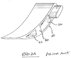
- FIGS. 2A and 2B each illustrate another prior art vane 20 that is constructed having a non-solid construction.
- such prior art vane 20 is configured having axial surfaces 22 and 24 that, unlike the solid vane discussed above, have axial surfaces that are substantially cored or hollowed-out.
- vane axial surface 22 is defined by two cored-out sections 26 and 28 that together occupy a major portion of the axial surface area.
- the vane axial surface 22 includes a solid section 30, that is disposed between the two cored-out sections 26 and 38, and that represents a minor portion of the axial surface area.
- vane axial surface 24 is defined by two cored-out sections 32 and 34 that together occupy a major portion of the of the axial surface area.
- the vane axial surface 24 includes an opening 36 disposed between the two cored-out sections, and is positioned opposite from the solid section 30 of the opposed vane axial surface 22.
- This prior art cored-out vane is useful in providing a vane structure having reduced weight, thereby reducing the effort and frictional wear associated with moving vanes of this construction within a turbocharger, and having a reduced expense.
- the cored-out structure of such vanes may operate to permit undesired air flow effects to occur within the turbocharger.
- the cored-out vane axial surfaces may operate two provide a leak path for air directed onto the vane's airfoil surfaces.
- air being directed to the vane leading edge and airfoil surfaces, rather then being directed along the airfoil surfaces can leak between the vane axial surfaces and adjacent turbocharger surfaces due to the reduced resistance to airflow that is provided by the core-out configuration.
- Such vane leakage within the turbocharger is not desired as it adversely impacts turbocharger operating efficiency.
- variable geometry assemblies for turbochargers.
- the variable geometry assemblies comprise vanes which are actuated in order to enable the adjustment of the geometry of a nozzle formed in a housing.
- US 2002/094284 A1 discloses a turbocharger having a plurality of vanes which enable a variable geometry of the nozzle formed in a housing.
- the vanes are constructed by an outer contour and actuating tabs engaging with a unison ring. Further, the vanes comprise cavities on axial faces.
- a vane be constructed for use within a variable geometry turbocharger that has a reduced weight, when compared to a conventional solid construction vane, and that minimizes or eliminates unwanted airflow effects within the turbocharger associated with air leakage across the vane, thereby providing improved vane operational reliability and turbocharger efficiency.
- Vanes of this invention are disposed within a variable geometry turbocharger assembly that comprises a turbine housing having an exhaust gas inlet and an outlet, a volute connected to the inlet, and a nozzle wall adjacent the volute.
- a turbine wheel is carried within the turbine housing and is attached to a shaft.
- a plurality of such vanes are disposed within the turbine housing between the exhaust gas inlet and turbine wheel,
- Vanes of this invention comprises an inner airfoil surfaces oriented adjacent the turbine wheel, and an outer airfoil surface oriented opposite and generally parallel to the inner airfoil surface.
- First and second axial surfaces are each positioned perpendicular to and interposed between the inner and outer airfoil surfaces.
- a vane leading edge is positioned along a first inner and outer airfoil surface junction.
- a vane trailing edge is positioned along a second inner and outer airfoil surface junction.
- Vanes of this invention also includes a hole disposed within at least one of the first and second axial surfaces for receiving a post therein.
- each of the first and second axial surfaces comprises a composite construction of a solid section and a cored-out section.
- the solid section extends a distance from the leading edge towards the trailing edge
- the cored-out section extends a distance from the trailing edge towards the leading edge.
- the solid and cored-out sections are positioned and configured to minimize or eliminate the undesired passage of gas along the vane axial surface, thereby operating to increase turbocharger operating efficiency.
- Vanes of this invention constructed for use in a variable geometry turbocharger, are configured having axial surfaces that are each characterized by strategically positioned cored-out and solid surfaces. More specifically, vanes of this invention have a first axial surface that is solid along a major surface area, and a second axial surface that is cored-out along a major surface area. Each of the first and second axial surfaces also include respective cored-out and solid sections that occupies a minor surface area of the respective axial surface. Vanes of this invention are so configured to minimize or eliminate possible leak paths across the vane axial surfaces during turbocharger operation.
- Vanes of this invention are disposed within a variable geometry or variable nozzle turbocharger.
- Such variable geometry turbochargers generally comprise a center housing having a turbine housing attached at one end, and a compressor housing attached at an opposite end.
- a shaft is rotatably disposed within a bearing assembly contained within the center housing.
- a turbine or turbine wheel is attached to one shaft end and is carried within the turbine housing, and a compressor impeller is attached to an opposite shaft end and is carried within the compressor housing.
- the turbine and compressor housings are attached to the center housing by, for example, bolts that extend between the adjacent housings.
- FIG. 3 illustrates a portion of a known variable nozzle turbocharger 38 comprising a turbine housing 40 having a standard inlet 42 for receiving an exhaust gas stream, and an outlet 44 for directing exhaust gas to the exhaust system of the engine.
- a volute is connected to the exhaust inlet and an outer nozzle wall is incorporated in the turbine housing casting adjacent the volute.
- a turbine wheel and shaft assembly 46 is carried within the turbine housing. Exhaust gas, or other high energy gas supplying the turbocharger, enters the turbine through the inlet and is distributed through the volute in the turbine housing for substantially radial entry into the turbine wheel through a circumferential nozzle entry 48.
- vanes 50 are mounted to a nozzle wall 52 by shafts 54 that project perpendicularly therebetween.
- the shafts are disposed within respective openings 56 in the nozzle wall.
- the vanes each include actuation tabs 58 that project from a side opposite the shafts and that are engaged by respective slots 60 in a unison ring 62, which acts as a second nozzle wall.
- An actuator assembly is connected with the unison ring and is configured to rotate the ring in one direction or the other as necessary to move the vanes radially, with respect to an axis of rotation of the turbine wheel, outwardly or inwardly to respectively increase or decrease the flow of exhaust gas to the turbine.
- the vane tabs 58 are caused to move within their respective slot 60 from one slot end to an opposite slot end. Since the slots are oriented with a radial directional component along the unison ring, the movement of the vane tabs within the respective slots causes the vanes to pivot via rotation of the vane shafts within their respective openings and open or close the nozzle area depending on the unison ring rotational direction.
- An example of known variable nozzle turbochargers comprising such elements is disclosed in U.S. Patent Nos. 6,269,642 and 6,419,464 , which are incorporated herein by reference.
- variable geometry turbochargers comprising the arrangement of multiple vanes described above and illustrated in FIG. 3 , requires that the vanes be configured to facilitate both desired vane movement in a manner that does not produce excessive frictional wear, e.g., be of a lightweight design, and efficient flow of gas within the turbine housing, e.g., not promote gas flow leakage.
- FIGS. 4A and 4B illustrate an example embodiment vane 64 of this invention that has been specially designed for application within a variable geometry turbocharger, such as that described above and illustrated in FIG. 3 , to address all of these needs.
- FIG. 5 also shows a horizontal cross section of the vane for purposes of providing further reference for those vane elements discussed below.
- the vane 64 includes an outer or low-pressure airfoil surface 66, an opposite inner or highpressure airfoil surface 68, and axial surfaces 70 and 72 (shown in FIG. 4B ). These vane surfaces are defined relative to the vane placement within the turbine housing.
- the vane 64 includes a leading edge 74 and a trailing edge 76 at opposite common ends of the low and high pressure airfoil surfaces 66 and 68.
- the vane includes a tab 78 that is positioned adjacent the leading edge 74, and that projects outwardly away from the axial surface 70.
- the tab 78 is configured to cooperate with a unison ring slot in the manner described above to facilitate vane actuation.
- Vanes of this invention can comprise airfoil surface configurations other than that disclosed and illustrated above.
- vanes of this invention can have an airfoil or radial thickness (as measured between opposed outer and inner airfoil surfaces) that can be greater than about 0.16 the length of the vane, e.g., in the range of from about 0.16 to 0.50 the length of the vane (as measured by a straight line between the vane leading and trailing edges).
- the outer airfoil surface can comprise a convex surface having a radius of curvature that is less than about 0.8 times a length of the vane.
- the vane leading edge is characterized by having relatively large radius of curvature such that an adjacent portion of the outer airfoil surface is located a relatively great distance from the actuation tab, thereby operating to provide an increased thickness adjacent the leading edge.
- the inner airfoil surface can have a complex shape that is defined by at least two differently shaped sections. Moving from the leading edge, the inner airfoil surface has a convex-shaped portion defined by a radius of curvature that is greater than that of the leading edge to contour or blend the leading edge into the inner surface. The convex-shaped portion extends from the leading edge 74 to just past the tab 78. Moving from the convex-shaped portion, the inner surface has a concave-shaped portion that extends to the vane trailing edge.
- the vane axial surface 70 comprises a composite construction of both solid and cored-out surface sections that are specifically positioned to avoid unwanted gas flow leakage along the axial surface.
- the term solid is used to refer to the fact that the designated surface portion is flat or planar, and is not recessed relative to the bounding edges of the inner and outer airfoil surfaces.
- the vane axial surface 70 comprises a solid section 80 that extends between the outer and inner airfoil surfaces 66 and 68, from the vane leading edge 74 to a shaft opening 82.
- the tab 78 projects from this solid section 80, and the solid section occupies a substantial surface area of the axial surface 70.
- the solid section occupies greater than about 25 percent, preferably greater than about 50 percent, and more preferably greater than 55 percent, of the axial surface area.
- the portion of the vane axial surface 70 that is exposed to high pressure differential within the turbocharger, and the portion of the vane most subject to gas leakage, is the portion of the vane that corresponds to the overlay of the unison ring and, more specifically, the overlay of the unison ring slots. It is theorized that high pressure gas can be directed through the unison ring via the slots and onto the vane axial surface. For this reason, the axial surface 70 is configured having the solid section 80 positioned to correspond with the unison ring slot to minimize the leak path for any high pressure gas being passed through the slot.
- the opening 82 is configured to accept placement of a shaft therein to permit pivoting vane movement within the turbocharger.
- the opening 82 extends completely through the vane and comprises a recessed surface section 84 positioned concentrically therearound.
- the recessed surface section 84 operates to facilitate flattening operations such as coining.
- a tight flatness tolerance on the axial face 70 of the vane is important for the purpose of reducing leak paths, and addressing associated efficiency losses.
- the vane axial surface 70 comprises a hollow or cored-out section 86 that extends from a wall 88, defining a portion of the shaft opening 82, a distance towards the trailing edge 76.
- the cored-out section 86 is defined by opposite inside walls of the outer and inner airfoil surfaces.
- the cored-out section 86 occupies a minor surface area of the axial surface 70. In an example embodiment, the cored-out section 86 occupies less than about 40 percent, and preferably less than 35 percent, of the axial surface area.
- the portion of the vane axial surface 70 that is exposed to a relatively low pressure differential is the portion of the vane extending from the shaft opening 82 to the trailing edge. For this reason, the potential for gas leakage is reduced and it is beneficial for purposes of reducing cost and rotating mass to construct this section having a cored-out configuration.
- FIG. 4B illustrates another view of the vane 64 from the other axial surface 72.
- Axial surface 72 comprises a composite construction of both solid and cored-out surface sections that, like the axial surface 70, are specifically positioned to avoid unwanted gas flow leakage thereacross. Features of this vane axial surface are also shown in FIG. 5 .
- the vane axial surface 72 comprises a hollow or cored-out section 90 that extends between the outer and inner airfoil surfaces 66 and 68, from the vane leading edge 74 to the shaft opening 82.
- the cored-out section 90 is defined by opposite inside walls of the outer and inner airfoil surfaces, and by a wall section 92 that defines the shaft opening 82 extending through the vane. As best illustrated in FIG. 5 , in an example embodiment, the cored-out section 90 has a depth defined by an inside wall portion 94 of the solid section 80 disposed along the opposite axial surface 70. The cored-out section 90 occupies a portion of the axial surface 72 that is substantially similar or equal to the portion of the axial surface 70 occupied by the solid section 80. In such example embodiment, the cored-out section 90 occupies a substantial surface area of the axial surface 72, e.g., occupying greater than about 50 percent, and preferably greater than 55 percent, of the axial surface area.
- the axial surface 72 includes a recessed surface section 96 positioned concentrically around the shaft opening 82.
- the recessed surface section 96 operates to facilitate flattening operations such as coining.
- a tight flatness tolerance on the axial face 72 of the vane is important for the purpose of reducing leak paths, and reducing associated efficiency losses.
- the vane axial surface 72 further comprises a solid section 98 that extends from the shaft opening 82, a distance towards the trailing edge 76.
- the solid section 98 is defined by the outer and inner airfoil surfaces, and occupies a minor surface area of the axial surface 72.
- the solid section 98 occupies a portion of the axial surface 72 that is substantially similar or equal to the portion of the axial surface 70 occupied by the cored-out section 86. In an example embodiment, the solid section 98 occupies less than about 40 percent, and preferably less than 35 percent, of the axial surface area.
- the portion of the vane axial surface 72 that is exposed to high pressure differential within the turbocharger, and the portion of the vane most subject to gas leakage, is the portion of the vane that is adjacent the trailing edge.
- This portion of the vane was found, through experimentation, to measurably impact turbine efficiency.
- the axial surface 72 is configured having the solid section 98 positioned between the hole and the trailing edge to minimize the leak path for any high pressure gas.
- the portion of the vane axial surface 72 that is exposed to a relatively low pressure differential is the portion of the vane extending from the leading edge to the shaft opening 82.
- Vanes of this invention are intentionally configured having with axial surface sections comprising a composite of solid and cored-out sections.
- the solid and cored-out sections are positioned on one vane axial surface opposite from respective cored-out and solid sections on the other vane axial surface.
- the solid and cored-out sections are located adjacent the vane leading or trailing edges. Vanes of this invention, configured in the manner described and illustrated above, minimize leakage of gas between vane axial surfaces and adjacent turbocharger surfaces, when placed into use within a turbocharger assembly illustrated in FIG. 3 , by providing a minimized leak path of solid and cored-out portions along each axial surface.
- vanes of this invention can comprise axial surfaces having composite constructions of solid and cored-out sections that are arranged differently than described and illustrated, depending on the particular turbocharger configuration and turbocharger application.
- vanes of this invention may have the solid and cored-out sections positioned differently along the axial surfaces to address differently positioned high pressure differentials within the turbocharger.
- at least one of the vane axial surfaces comprise a composite of cored-out and solid sections.
- Vanes of this invention can be formed from the same types of materials used to form conventional prior art vanes. Vanes of this invention can be formed by machining or molding process. In a preferred embodiment, vanes of this invention are formed by metal injection molding technique. Vanes of this invention provide a desired a cost effective and light weight alternative to solid vanes, while at the same time minimizing or eliminating undesired gas leakage effects within the turbocharger. Thus, vanes of this invention operate to improve vane mobility, reduce frictional wear effects, improve turbocharger operational efficiency, and extend turbocharger operational service life.
Claims (12)
- Ensemble formant turbocompresseur à géométrie variable comprenant :un carter de turbine (40) comportant une entrée de gaz d'échappement (42) et une sortie (44), une volute raccordée à l'entrée (42), et une paroi de distributeur adjacente à la volute ;une roue de turbine supportée à l'intérieur du carter de turbine (40) et fixée à un arbre (46) ;une pluralité d'aubes (50) disposées à l'intérieur du carter de turbine (40) entre l'entrée de gaz d'échappement (42) et la roue de turbine, chaque aube (50) comprenant :une surface intérieure de composant aérodynamique (68) orientée de manière adjacente à la roue de turbine ;une surface extérieure de composant aérodynamique (66) orientée de manière opposée et parallèle à la surface intérieure de composant aérodynamique ;des première et seconde surfaces axiales (70, 72) positionnées chacune perpendiculairement aux surfaces intérieure et extérieure de composant aérodynamique (68, 66) et intercalées entre celles-ci ;un bord d'attaque (74) positionné le long d'une première jonction entre surfaces intérieure et extérieure de composant aérodynamique ;un bord de fuite (76) positionné le long d'une seconde jonction entre surfaces intérieure et extérieure de composant aérodynamique ;caractérisé en ce quechacune des première et seconde surfaces axiales (70, 72) comprend une construction composite constituée d'une section pleine (80) et d'une section évidée (86), la section pleine (80) d'une surface parmi les première et seconde surfaces axiales (70, 72) occupant au moins 25 pour cent de l'aire axiale s'étendant du bord d'attaque (74) en direction du bord de fuite (76), et la section évidée (86) pour la même surface parmi les première et seconde surfaces axiales (70, 72) s'étendant du bord de fuite (76) en direction du bord d'attaque (74), et en ce quela section pleine (80) de la première surface axiale (70) est positionnée de manière opposée à la section évidée (90) de la seconde surface axiale (72).
- Ensemble selon la revendication 1, dans lequel chaque aube (50) comprend en outre une ouverture (82) à l'intérieur d'au moins une des première et seconde surfaces axiales (70, 72) destinée à recevoir un axe, et dans lequel la section pleine (80) s'étend du bord d'attaque (74) à l'ouverture, et la section évidée (86) s'étend du trou jusqu' à un emplacement adjacent au bord de fuite (76).
- Ensemble selon la revendication 1, dans lequel la section pleine (80) occupe plus de 50 pour cent de l'aire de la première surface axiale.
- Ensemble selon la revendication 1, comprenant en outre une protubérance (78) faisant saillie vers l'extérieur à partir de la section pleine (80) et positionnée de manière adjacente au bord d'attaque (74).
- Ensemble selon la revendication 2, dans lequel l'ouverture (82) s'étend à travers l'aube (50), de la première surface axiale (70) à la seconde surface axiale (72), dans lequel la première surface axiale comprend la section pleine (80) s'étendant du bord d'attaque (74) à l'ouverture, et la section évidée (86) s'étendant de l'ouverture jusqu'à un emplacement adjacent au bord de fuite (76), et dans lequel la seconde surface axiale (72) comprend la section évidée s'étendant du bord d'attaque (74) à l'ouverture, et la section pleine s'étendant de l'ouverture au bord de fuite.
- Ensemble selon la revendication 5, dans lequel la section pleine (80) de la première surface axiale (70) occupe la plus grande partie de la première surface axiale, et la section évidée (86) de la seconde surface axiale occupe la plus grande partie de la seconde surface axiale (72).
- Ensemble selon la revendication 5, comprenant en outre une protubérance (78) faisant saillie vers l'extérieur à partir de la première surface axiale (70) et positionnée de manière adjacente au bord d'attaque (74).
- Ensemble selon la revendication 1, dans lequel la seconde surface axiale (72) est positionnée de manière adjacente à la paroi de distributeur ; comprenant en outre :une ouverture (82) disposée à travers la seconde surface axiale (72) et destinée à recevoir un axe dans celle-ci qui est intercalé entre l'aube (50) et la paroi de distributeur ; etdes moyens d'actionnement positionnés sur la première surface axiale (70) ;une bague de commande synchronisée annulaire (62) positionnée de manière adjacente aux aubes (50) le long de la première surface axiale (70) et comprenant des moyens destinés à coopérer avec les moyens d'actionnement de façon à interagir avec la pluralité d'aubes (50) afin de tourner les aubes (50) à l'intérieur du turbocompresseur.
- Ensemble selon la revendication 8, dans lequel la section pleine s'étend, le long de la première surface axiale (70), du bord d'attaque (74) jusqu'à un emplacement adjacent à l'ouverture (82) dans la seconde surface axiale (72), et la section pleine s'étend, le long de la seconde surface axiale (72), de l'ouverture au bord de fuite (76).
- Ensemble selon la revendication 9, dans lequel la section évidée (86) s'étend, le long de la première surface axiale (70), d'un emplacement adjacent au bord de fuite (76) jusqu'à un emplacement adjacent à l'ouverture (82) dans la seconde surface axiale (72), et la section évidée s'étend, le long de la seconde surface axiale (72), du bord d'attaque (74) jusqu'à un emplacement adjacent à l'ouverture.
- Ensemble selon la revendication 9, dans lequel la section pleine (80) de l'au moins une des première et seconde surfaces axiales occupe au moins 50 pour cent de l'aire de ladite ou desdites surfaces axiales, mesurée entre les bords d'attaque et de fuite (74, 76).
- Ensemble selon la revendication 8, dans lequel le moyen d'actionnement est une protubérance (58) faisant saillie vers l'extérieur à partir de l'aube (50), et le moyen coopérant est une fente (60).
Applications Claiming Priority (2)
| Application Number | Priority Date | Filing Date | Title |
|---|---|---|---|
| US10/671,751 US7059129B2 (en) | 2003-09-25 | 2003-09-25 | Variable geometry turbocharger |
| PCT/US2004/031338 WO2005031120A1 (fr) | 2003-09-25 | 2004-09-24 | Turbocompresseur a geometrie variable |
Publications (2)
| Publication Number | Publication Date |
|---|---|
| EP1668225A1 EP1668225A1 (fr) | 2006-06-14 |
| EP1668225B1 true EP1668225B1 (fr) | 2018-06-20 |
Family
ID=34376180
Family Applications (1)
| Application Number | Title | Priority Date | Filing Date |
|---|---|---|---|
| EP04784953.4A Active EP1668225B1 (fr) | 2003-09-25 | 2004-09-24 | Turbocompresseur a geometrie variable |
Country Status (4)
| Country | Link |
|---|---|
| US (1) | US7059129B2 (fr) |
| EP (1) | EP1668225B1 (fr) |
| JP (1) | JP2007519845A (fr) |
| WO (1) | WO2005031120A1 (fr) |
Families Citing this family (22)
| Publication number | Priority date | Publication date | Assignee | Title |
|---|---|---|---|---|
| US7305826B2 (en) * | 2005-02-16 | 2007-12-11 | Honeywell International , Inc. | Axial loading management in turbomachinery |
| US8112995B2 (en) * | 2006-06-19 | 2012-02-14 | Turbo Energy Limited | Turbocharger with variable turbine geometry |
| US7712311B2 (en) | 2007-03-14 | 2010-05-11 | Gm Global Technology Operations, Inc. | Turbocharger assembly with catalyst coating |
| DE102008058509A1 (de) * | 2008-11-21 | 2010-05-27 | Bosch Mahle Turbo Systems Gmbh & Co. Kg | Ladeeinrichtung |
| GB0822474D0 (en) * | 2008-12-10 | 2009-01-14 | Cummins Turbo Tech Ltd | Variable geometry turbine nozzle ring |
| US8653687B2 (en) * | 2011-04-04 | 2014-02-18 | Ebara International Corporation | Liquefied gas expander nozzle ring having adjustable guide vanes |
| DE102011075794A1 (de) * | 2011-05-13 | 2012-11-15 | Bosch Mahle Turbo Systems Gmbh & Co. Kg | Variable Turbinen-/Verdichtergeometrie |
| US9388706B2 (en) * | 2012-02-24 | 2016-07-12 | Fluid Equipment Development Company | Method and system for tuning a turbine using secondary injection nozzles in nozzle ring |
| RU2014145727A (ru) * | 2012-04-24 | 2016-06-10 | Боргварнер Инк. | Сборка пакета лопаток для vtg турбонагнетателей |
| KR20140063474A (ko) | 2012-11-16 | 2014-05-27 | 에이비비 터보 시스템즈 아게 | 노즐 링 |
| USD777212S1 (en) * | 2015-06-20 | 2017-01-24 | General Electric Company | Nozzle ring |
| US20170057649A1 (en) | 2015-08-27 | 2017-03-02 | Edward C. Rice | Integrated aircraft propulsion system |
| US10233869B2 (en) | 2015-08-27 | 2019-03-19 | Rolls Royce North American Technologies Inc. | System and method for creating a fluidic barrier from the leading edge of a fan blade |
| US10125622B2 (en) | 2015-08-27 | 2018-11-13 | Rolls-Royce North American Technologies Inc. | Splayed inlet guide vanes |
| US10280872B2 (en) | 2015-08-27 | 2019-05-07 | Rolls-Royce North American Technologies Inc. | System and method for a fluidic barrier from the upstream splitter |
| US10718221B2 (en) | 2015-08-27 | 2020-07-21 | Rolls Royce North American Technologies Inc. | Morphing vane |
| US9915149B2 (en) | 2015-08-27 | 2018-03-13 | Rolls-Royce North American Technologies Inc. | System and method for a fluidic barrier on the low pressure side of a fan blade |
| US10267160B2 (en) | 2015-08-27 | 2019-04-23 | Rolls-Royce North American Technologies Inc. | Methods of creating fluidic barriers in turbine engines |
| US10267159B2 (en) | 2015-08-27 | 2019-04-23 | Rolls-Royce North America Technologies Inc. | System and method for creating a fluidic barrier with vortices from the upstream splitter |
| US9976514B2 (en) | 2015-08-27 | 2018-05-22 | Rolls-Royce North American Technologies, Inc. | Propulsive force vectoring |
| USD849797S1 (en) * | 2015-12-01 | 2019-05-28 | Ge Global Sourcing Llc | Blower assembly |
| US10207471B2 (en) * | 2016-05-04 | 2019-02-19 | General Electric Company | Perforated ceramic matrix composite ply, ceramic matrix composite article, and method for forming ceramic matrix composite article |
Family Cites Families (13)
| Publication number | Priority date | Publication date | Assignee | Title |
|---|---|---|---|---|
| US3232581A (en) * | 1963-07-31 | 1966-02-01 | Rotoflow Corp | Adjustable turbine inlet nozzles |
| US3495921A (en) * | 1967-12-11 | 1970-02-17 | Judson S Swearingen | Variable nozzle turbine |
| US3645645A (en) | 1970-10-19 | 1972-02-29 | Garrett Corp | Variable-area nozzle seal |
| US4300869A (en) * | 1980-02-11 | 1981-11-17 | Swearingen Judson S | Method and apparatus for controlling clamping forces in fluid flow control assemblies |
| US4502836A (en) | 1982-07-02 | 1985-03-05 | Swearingen Judson S | Method for nozzle clamping force control |
| FR2617119B1 (fr) * | 1987-06-26 | 1989-12-01 | Aerospatiale | Pale en materiaux composites, a noyau structural et revetement d'habillage profile, et son procede de fabrication |
| US5127802A (en) * | 1990-12-24 | 1992-07-07 | United Technologies Corporation | Reinforced full-spar composite rotor blade |
| US5392514A (en) * | 1992-02-06 | 1995-02-28 | United Technologies Corporation | Method of manufacturing a composite blade with a reinforced leading edge |
| US6269642B1 (en) * | 1998-10-05 | 2001-08-07 | Alliedsignal Inc. | Variable geometry turbocharger |
| US6419464B1 (en) * | 2001-01-16 | 2002-07-16 | Honeywell International Inc. | Vane for variable nozzle turbocharger |
| US6729134B2 (en) * | 2001-01-16 | 2004-05-04 | Honeywell International Inc. | Variable geometry turbocharger having internal bypass exhaust gas flow |
| US6547520B2 (en) * | 2001-05-24 | 2003-04-15 | Carrier Corporation | Rotating vane diffuser for a centrifugal compressor |
| US6709230B2 (en) * | 2002-05-31 | 2004-03-23 | Siemens Westinghouse Power Corporation | Ceramic matrix composite gas turbine vane |
-
2003
- 2003-09-25 US US10/671,751 patent/US7059129B2/en not_active Expired - Lifetime
-
2004
- 2004-09-24 EP EP04784953.4A patent/EP1668225B1/fr active Active
- 2004-09-24 WO PCT/US2004/031338 patent/WO2005031120A1/fr active Application Filing
- 2004-09-24 JP JP2006528195A patent/JP2007519845A/ja active Pending
Non-Patent Citations (1)
| Title |
|---|
| None * |
Also Published As
| Publication number | Publication date |
|---|---|
| JP2007519845A (ja) | 2007-07-19 |
| US7059129B2 (en) | 2006-06-13 |
| EP1668225A1 (fr) | 2006-06-14 |
| US20050066657A1 (en) | 2005-03-31 |
| WO2005031120A1 (fr) | 2005-04-07 |
Similar Documents
| Publication | Publication Date | Title |
|---|---|---|
| EP1668225B1 (fr) | Turbocompresseur a geometrie variable | |
| EP1352157B1 (fr) | Turbocompresseur à géométrie variable avec un positionnement d'aubes amélioré | |
| US6729134B2 (en) | Variable geometry turbocharger having internal bypass exhaust gas flow | |
| EP1714008B1 (fr) | Turbocompresseur | |
| US10408228B2 (en) | Mixed-flow turbocharger with variable turbine geometry | |
| EP1740798B1 (fr) | Ensemble ameliore a geometrie variable destine aux turbocompresseurs | |
| US8721268B2 (en) | Turbomachine | |
| EP2233720B1 (fr) | Procédé de fabrication d'une turbine à gaz d'échappement à capacité variable | |
| JP2003035151A (ja) | 可変形状タービン | |
| EP2035673B1 (fr) | Mécanisme à aubes de stator à calage variable pour turbocompresseurs | |
| JP2017515051A (ja) | 可変ジオメトリタービンアセンブリ | |
| US6599087B2 (en) | Actuator shaft seal for variable nozzle turbocharger | |
| US7762067B2 (en) | Turbocharger with sliding piston assembly | |
| US20240125240A1 (en) | Turbine Assembly | |
| US8747057B2 (en) | Turbomachine | |
| WO2008139130A1 (fr) | Turbine à géométrie variable | |
| CN108442981B (zh) | 一种双活塞环可变喷嘴组件 | |
| WO2020261417A1 (fr) | Dispositif de buse variable et turbocompresseur d'échappement de type à capacité variable | |
| CN116357408A (zh) | 双涡管涡轮壳体 | |
| KR20040088574A (ko) | 가변 형상 과급기에 사용되는 개선된 베인 | |
| EP2486245A2 (fr) | Turbine a geometrie variable |
Legal Events
| Date | Code | Title | Description |
|---|---|---|---|
| PUAI | Public reference made under article 153(3) epc to a published international application that has entered the european phase |
Free format text: ORIGINAL CODE: 0009012 |
|
| 17P | Request for examination filed |
Effective date: 20060316 |
|
| AK | Designated contracting states |
Kind code of ref document: A1 Designated state(s): DE FR GB |
|
| 17Q | First examination report despatched |
Effective date: 20060821 |
|
| DAX | Request for extension of the european patent (deleted) | ||
| RBV | Designated contracting states (corrected) |
Designated state(s): DE FR GB |
|
| RAP1 | Party data changed (applicant data changed or rights of an application transferred) |
Owner name: HONEYWELL INTERNATIONAL INC. |
|
| GRAP | Despatch of communication of intention to grant a patent |
Free format text: ORIGINAL CODE: EPIDOSNIGR1 |
|
| INTG | Intention to grant announced |
Effective date: 20180208 |
|
| GRAS | Grant fee paid |
Free format text: ORIGINAL CODE: EPIDOSNIGR3 |
|
| GRAA | (expected) grant |
Free format text: ORIGINAL CODE: 0009210 |
|
| REG | Reference to a national code |
Ref country code: DE Ref legal event code: R081 Ref document number: 602004052844 Country of ref document: DE Owner name: GARRETT TRANSPORTATION I INC., TORRANCE, US Free format text: FORMER OWNER: HONEYWELL INTERNATIONAL INC., MORRISTOWN, N.J., US |
|
| AK | Designated contracting states |
Kind code of ref document: B1 Designated state(s): DE FR GB |
|
| REG | Reference to a national code |
Ref country code: GB Ref legal event code: FG4D |
|
| REG | Reference to a national code |
Ref country code: DE Ref legal event code: R096 Ref document number: 602004052844 Country of ref document: DE |
|
| REG | Reference to a national code |
Ref country code: FR Ref legal event code: PLFP Year of fee payment: 15 |
|
| REG | Reference to a national code |
Ref country code: DE Ref legal event code: R097 Ref document number: 602004052844 Country of ref document: DE |
|
| RAP2 | Party data changed (patent owner data changed or rights of a patent transferred) |
Owner name: GARRETT TRANSPORTATION I INC. |
|
| PLBE | No opposition filed within time limit |
Free format text: ORIGINAL CODE: 0009261 |
|
| STAA | Information on the status of an ep patent application or granted ep patent |
Free format text: STATUS: NO OPPOSITION FILED WITHIN TIME LIMIT |
|
| 26N | No opposition filed |
Effective date: 20190321 |
|
| REG | Reference to a national code |
Ref country code: DE Ref legal event code: R082 Ref document number: 602004052844 Country of ref document: DE Representative=s name: TBK, DE Ref country code: DE Ref legal event code: R082 Ref document number: 602004052844 Country of ref document: DE Ref country code: DE Ref legal event code: R081 Ref document number: 602004052844 Country of ref document: DE Owner name: GARRETT TRANSPORTATION I INC., TORRANCE, US Free format text: FORMER OWNER: HONEYWELL INTERNATIONAL INC., MORRIS PLAINS, N.J., US |
|
| REG | Reference to a national code |
Ref country code: GB Ref legal event code: 732E Free format text: REGISTERED BETWEEN 20190725 AND 20190731 |
|
| REG | Reference to a national code |
Ref country code: DE Ref legal event code: R082 Ref document number: 602004052844 Country of ref document: DE |
|
| PGFP | Annual fee paid to national office [announced via postgrant information from national office to epo] |
Ref country code: GB Payment date: 20230926 Year of fee payment: 20 |
|
| PGFP | Annual fee paid to national office [announced via postgrant information from national office to epo] |
Ref country code: FR Payment date: 20230926 Year of fee payment: 20 Ref country code: DE Payment date: 20230928 Year of fee payment: 20 |