EP1667813B1 - Appareil et procédé améliorés de fronçage de filet - Google Patents
Appareil et procédé améliorés de fronçage de filet Download PDFInfo
- Publication number
- EP1667813B1 EP1667813B1 EP04789328.4A EP04789328A EP1667813B1 EP 1667813 B1 EP1667813 B1 EP 1667813B1 EP 04789328 A EP04789328 A EP 04789328A EP 1667813 B1 EP1667813 B1 EP 1667813B1
- Authority
- EP
- European Patent Office
- Prior art keywords
- tube
- netting
- ring
- annular space
- outer diameter
- Prior art date
- Legal status (The legal status is an assumption and is not a legal conclusion. Google has not performed a legal analysis and makes no representation as to the accuracy of the status listed.)
- Not-in-force
Links
Images


Classifications
-
- A—HUMAN NECESSITIES
- A22—BUTCHERING; MEAT TREATMENT; PROCESSING POULTRY OR FISH
- A22C—PROCESSING MEAT, POULTRY, OR FISH
- A22C13/00—Sausage casings
- A22C13/02—Shirring of sausage casings
-
- A—HUMAN NECESSITIES
- A22—BUTCHERING; MEAT TREATMENT; PROCESSING POULTRY OR FISH
- A22C—PROCESSING MEAT, POULTRY, OR FISH
- A22C13/00—Sausage casings
- A22C13/02—Shirring of sausage casings
- A22C2013/026—Shirring netting onto a tube
-
- B—PERFORMING OPERATIONS; TRANSPORTING
- B65—CONVEYING; PACKING; STORING; HANDLING THIN OR FILAMENTARY MATERIAL
- B65B—MACHINES, APPARATUS OR DEVICES FOR, OR METHODS OF, PACKAGING ARTICLES OR MATERIALS; UNPACKING
- B65B9/00—Enclosing successive articles, or quantities of material, e.g. liquids or semiliquids, in flat, folded, or tubular webs of flexible sheet material; Subdividing filled flexible tubes to form packages
- B65B9/10—Enclosing successive articles, or quantities of material, in preformed tubular webs, or in webs formed into tubes around filling nozzles, e.g. extruded tubular webs
- B65B9/15—Enclosing successive articles, or quantities of material, in preformed tubular webs, or in webs formed into tubes around filling nozzles, e.g. extruded tubular webs the preformed tubular webs being stored on filling nozzles
- B65B9/18—Devices for storing tubular webs
-
- Y—GENERAL TAGGING OF NEW TECHNOLOGICAL DEVELOPMENTS; GENERAL TAGGING OF CROSS-SECTIONAL TECHNOLOGIES SPANNING OVER SEVERAL SECTIONS OF THE IPC; TECHNICAL SUBJECTS COVERED BY FORMER USPC CROSS-REFERENCE ART COLLECTIONS [XRACs] AND DIGESTS
- Y10—TECHNICAL SUBJECTS COVERED BY FORMER USPC
- Y10T—TECHNICAL SUBJECTS COVERED BY FORMER US CLASSIFICATION
- Y10T29/00—Metal working
- Y10T29/49—Method of mechanical manufacture
- Y10T29/49826—Assembling or joining
- Y10T29/49838—Assembling or joining by stringing
-
- Y—GENERAL TAGGING OF NEW TECHNOLOGICAL DEVELOPMENTS; GENERAL TAGGING OF CROSS-SECTIONAL TECHNOLOGIES SPANNING OVER SEVERAL SECTIONS OF THE IPC; TECHNICAL SUBJECTS COVERED BY FORMER USPC CROSS-REFERENCE ART COLLECTIONS [XRACs] AND DIGESTS
- Y10—TECHNICAL SUBJECTS COVERED BY FORMER USPC
- Y10T—TECHNICAL SUBJECTS COVERED BY FORMER US CLASSIFICATION
- Y10T29/00—Metal working
- Y10T29/49—Method of mechanical manufacture
- Y10T29/49826—Assembling or joining
- Y10T29/49879—Spaced wall tube or receptacle
-
- Y—GENERAL TAGGING OF NEW TECHNOLOGICAL DEVELOPMENTS; GENERAL TAGGING OF CROSS-SECTIONAL TECHNOLOGIES SPANNING OVER SEVERAL SECTIONS OF THE IPC; TECHNICAL SUBJECTS COVERED BY FORMER USPC CROSS-REFERENCE ART COLLECTIONS [XRACs] AND DIGESTS
- Y10—TECHNICAL SUBJECTS COVERED BY FORMER USPC
- Y10T—TECHNICAL SUBJECTS COVERED BY FORMER US CLASSIFICATION
- Y10T29/00—Metal working
- Y10T29/53—Means to assemble or disassemble
- Y10T29/53657—Means to assemble or disassemble to apply or remove a resilient article [e.g., tube, sleeve, etc.]
Definitions
- This invention relates to the field of preparing food products in shirred, tubular casings and enclosing the products in a netting.
- One method generally used in the industry is to pump food products, such as sausage meat, whole muscle meats, or otherwise, through a product horn.
- the meat products are forced into an edible film and then into netting.
- the food products to be packaged will expand and push the film through the netting.
- After processing, such as smoking or cooking the netting will be removed, leaving a dimpled appearance on the food products that is considered pleasing to consumers.
- the edible casing will prevent the netting from sticking to the meat, so upon removal of the netting a clean appearance of the meat is maintained.
- the netting used in this process arrives from the manufacturers in a flattened state and wrapped circumferentially on a disposable cylinder.
- the netting has to be shirred onto a temporary netting tube.
- This shirring process or "rucking", involves placing the netting coaxially onto the netting tube.
- the tube is place on a sausage making machine for extrusion of sausage, as described in U.S. patents nos. 4,910,034 and 4,958,477 and as illustrated in, for example, Figure 7 of those patents.
- a netting tube is caused to reciprocate vertically, such as by use of an air cylinder.
- the netting is stretched over the tube.
- a plurality of spring-loaded fingers secured to a bracket surround the netting tube circumferentially. These fingers are normally in a horizontal position. Downward force moves them down; the springs cause them to snap back to the normal horizontal position when the force is removed. Accordingly, the fingers carry the netting downward during the upward stroke of the tube, and slide over the netting during the downward stroke of the tube.
- the reciprocating motion of the netting tube therefore causes the netting to be shirred onto the netting tube.
- This prior art is described in, for example, U.S. Patent No. 5,273,481 . Note that only one layer of netting is shirred onto the netting tube by this method.
- a prior art improvement is to add a second tube, which fits coaxially over the netting tube.
- the netting is stretched over the second tube.
- the second tube rises in relation to the netting tube and the netting is shirred onto the netting tube, in the space between the base of the netting tube and the now-rising second tube.
- More netting can be shirred onto the netting tube in this manner, as compared to the prior art method of the previous paragraph, because multiple layers can be shirred, thereby rucking more linear feet of netting per length of netting tube.
- the netting is not shirred particularly neatly by this method. It bunches up and is wavy.
- This prior art improvement used a second tube with a larger inside diameter than the outside diameter of the netting tube. Accordingly, a tube cap is inserted into the top of the second tube, to keep the second tube moving coaxially to the netting tube, and to allow the netting to slide smoothly over the second tube. A coaxial ring in the bottom of the second tube keeps the second tube coaxial to the netting tube, and will push the netting downward on the netting tube.
- One embodiment of the present invention is an improvement to the prior art comprising placing a coaxial ring between the netting tube and the second tube, a distance from the bottom end of the second tube, creating an annular space defined by the netting tube, the ring, and the second tube.
- the netting curls underneath the second tube and fills this annular space first.
- netting is shirred over the netting that had been shirred into this annular space.
- This method causes the netting to be shirred neatly, in multiple layers, without waviness, and allows more netting to be shirred onto a given length of netting tube.
- the preferred embodiment of the net rucking apparatus 2 is shown in elevation view in Figure1 without the netting 4 present, and in Figure 1A with the netting 4 present.
- the apparatus 2 comprises a frame 10, a netting tube 40, and a second tube 50.
- the frame 10 has legs 12 to support it, and upper arms 14 that hold a net rucker head 16.
- the net rucker head 16 defines a passage 18 through which the netting tube 40 and second tube 50 pass. Attached to the net rucker head 16 and extending into the passage 18 are a plurality of spring-loaded fingers 20.
- a moveable platform 22 sits on top of the frame 10. It is configured to travel in an upward and downward direction, powered by lifting means.
- the lifting means comprise an air-actuated cylinder 24, connected to an air supply 26 which is controlled by a control means 28. Any lifting means that can provide reciprocating axial action will suffice, such as a gear arrangement, another type of hydraulic cylinder, or a treadle.
- the control means 28 is a microprocessor with an application specific program written to it, but any suitable controller, digital or analog, will suffice.
- Netting 4 is placed in a net tray 30 that is attached to an upper arm 14.
- the leading edge of the netting 4 travels up to a net guide 32, attached to and above one of the upper arms 14 and above the net rucker head 16.
- the net guide 32 leads the netting 4 down through the passage 18 as will hereinafter be described.
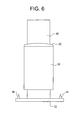
- the netting tube 40 shown enlarged in Figure 2 , is a hollow cylinder with a base plate 42.
- the netting tube 40 is stainless steel, for use in a food-processing environment.
- the attachment means 44 are preferably identical to the means by which the netting tube will be attached to a sausage-making machine after rucking of the netting 4.
- the attachment means 44 can be a simple nut-and-bolt arrangement, a locking clamp, or any system to hold the netting tube 40 firmly to the moveable platform 22.
- the second tube 50 shown in perspective view in Figure 3 , is also a hollow cylinder, with an inside diameter greater than the outside diameter of the netting tube 40.
- the second tube 50 is preferably made of a heavy plastic, to allow netting 4 to slide over it easily.
- a tube cap ring 52 At the top of the second tube 50 is placed a tube cap ring 52, shown in elevation view in Figure 2 .
- the tube cap ring 52 is a toroidal element with a notched edge 53, so that it has one outer diameter equal to the outer diameter of the second tube 50, and a second outer diameter equal to the inner diameter of the second tube 50, allowing the tube cap ring 52 to snap onto the top end of the second tube 50.
- the tube cap ring 52 has an inner diameter just slightly larger than the outer diameter of the netting tube 40, so that the tube cap ring 52 can slide easily axially to the netting tube 40.
- the tube cap ring 52 is rounded or at least angled on the side opposite the notched edge, to allow netting 4to slide over it easily, as the purpose of the tube cap ring 52 is to prevent snagging.
- the tube cap ring 52 stays firmly attached to the second tube 50 by an interference fit, but glue could also be used if necessary.
- a lower tube ring 54 shown in plan view in Figure 5 , is also of a toroidal shape and is placed inside and coaxially to the second tube 50.
- the lower tube ring 54 has an outer diameter equal to the inner diameter of the second tube 50 and forming an interference fit, so that the lower tube ring 54 stays firmly situated inside the second tube 50.
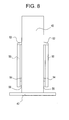
- the inner diameter of the lower tub ring 54 is, like the tube cap ring 52, just slightly larger than the outer diameter of the netting tube 40, so that the lower tube ring 54 can easily slide axially to the netting tube 40, as shown in elevation view in Figure 6 .
- the lower tube ring 54 is placed inside the second tube 50, a short distance, preferably an inch, from the bottom of the second tube, as shown in partial cutaway view in Figure 7 . Because the lower tube ring 54 is placed a short distance from the bottom end of the second tube 50, an annular space 56 is defined by the netting tube 40, lower tube ring 54, and the second tube 50.
- the tube cap ring 52 and the lower tube ring 54 slide easily along the netting tube 40, so that the second tube 50 travels coaxially to the netting tube 40.
- extra lower tube rings 54 can be placed inside the second tube 50. Only the lower tube ring 54 that defines the annular space 56 is necessary for this present invention, however.
- the second tube 50 has an inner diameter just slightly greater than the outer diameter of the netting tube 40. Instead of placing a lower tube ring 54 in the bore of the second tube 50, however, a notch is cut out of the lower end of the second tube 50, thereby forming the annular space 56.
- the netting tube 40 is placed on the moveable platform 22 and attached by the attachment means 44.
- the second tube 50 with its two rings 52, 54 in place, is placed over the netting tube 40.
- the spring-loaded fingers 20 are arranged so that they conform to the diameter of the second tube 50 and the netting tube 40. During downward travel of the second tube 50 and the netting tube 40, the fingers 20 are pushed away circumferentially from the two tubes 40 and 50, allowing netting 4 to travel in a downward direction. When the second tube 50 and netting tube 40 travel upward, the spring-loaded fingers 20 snap back to engage the netting and prevent it from traveling.
- the netting 4 is placed in the net tray 30 and the free end is run through the net guide 32 and over the second tube 50, to at least a point below the reciprocating fingers 20.
- the moveable platform 22 moves down, it pulls netting 4 down with it, past the spring-loaded fingers 20.
- the cylinder 24 reverses movement to an upward direction, pushing the netting tube 40 and second tube 50 through the passage 18.
- the spring-loaded fingers 20 now engage the netting 4 on the second tube 50 and prevent it from traveling.
- the second tube 50 nevertheless continues in an upward path, as the netting 4 can slide over the smooth plastic surface of the second tube 50, so the netting 4 moves downward relative to the second tube 50.
- the netting 4 is pulled down toward the bottom of the second tube 50.
- the spring-loaded fingers 20 push it off the second tube 50 and the netting 4 contracts around the smaller-diameter netting tube 40.
- the second tube 50 is forced slightly upward, relative to the netting tube 40, by the spring-loaded fingers 20, as netting 4 is rucked onto the bottom of the netting tube 40.
- more netting 4 is pushed by the spring-loaded fingers 20 off the second tube 50 and onto the netting tube 40.
- the spring-loaded fingers 20 push the netting4 inward, causing it to fill the annular space 56. Because of the annular space 56, the netting 4 is rucked neatly and several layers thick. Accordingly, the apparatus 2 will ruck approximately four to five times as much netting 4 onto a given size of netting tube 40 as a conventional rucker without this annular space.
Landscapes
- Life Sciences & Earth Sciences (AREA)
- Engineering & Computer Science (AREA)
- Wood Science & Technology (AREA)
- Zoology (AREA)
- Food Science & Technology (AREA)
- Containers And Plastic Fillers For Packaging (AREA)
- Meat, Egg Or Seafood Products (AREA)
- Treatment Of Fiber Materials (AREA)
- Wire Processing (AREA)
- Actuator (AREA)
- Soy Sauces And Products Related Thereto (AREA)
- Reciprocating Pumps (AREA)
Claims (10)
- Dispositif de fronçage d'un filet sur un tube, le dispositif comprenant un cadre (10) définissant un axe, un vérin (24) d'actionnement pour faire aller et venir une plateforme (22) le long de l'axe, un tube (40) pour filet ayant un diamètre extérieur et un axe et pouvant être adjoint de manière détachable à la plateforme (22), des doigts (20) soumis à l'action de ressorts adjoints au cadre (10) et s'étend circonférentiellement dans l'axe du cadre (10), formant un passage dans lequel le tube (40) pour filet se déplace lorsque le tube (40) pour filet est adjoint à la plateforme (22), et un deuxième tube (50) ayant un alésage d'un premier diamètre plus grand que le diamètre extérieur du tube (40) pour filet, le deuxième tube (50) pouvant être aligné de manière démontable coaxialement au tube (40) pour filet,
caractérisé en ce qu'un espace (56) annulaire est formé entre le tube (40) pour filet et le deuxième tube (50) par une encoche dans une extrémité du deuxième tube (50) ou par une bague (54) de tube placée entre le tube (40) pour filet et le deuxième tube (50) à une distance de l'extrémité du fond du deuxième tube (50), la bague (54) de tube ayant un diamètre extérieur égal au diamètre intérieur du deuxième tube (50) pour former un ajustement serré avec elle et un diamètre intérieur juste plus grand que le diamètre extérieur du tube (40) pour filet pour permettre à la bague (54) de tube de glisser axialement par rapport au tube (40) pour filet. - Dispositif suivant la revendication 1, dans lequel l'espace annulaire est formé par la bague (54) de tube alignée concentriquement à l'alésage du deuxième tube (50) et pouvant coulisser axialement sur le tube (40) pour filet.
- Dispositif suivant la revendication 2, comprenant, en outre, une bague (52) de coiffe de tube sur le deuxième tube (50) pour empêcher de faire un accroc au filet (4).
- Dispositif suivant la revendication 3, dans lequel la bague (52) de coiffe de tube a une surface conique.
- Dispositif suivant la revendication 1 ou 2, comprenant, en outre, une unité (28) de commande pour commander le mouvement d'aller et retour du vérin d'actionnement.
- Dispositif suivant la revendication 5, dans lequel le vérin (24) d'actionnement est un vérin (24) pneumatique ayant une alimentation (26) en air.
- Dispositif suivant la revendication 6, dans lequel une unité (28) de commande commande le vérin pneumatique.
- Procédé pour froncer un filet sur un tube (40) pour filet, le procédé comprenant l'adjonction d'un tube (40) pour filet à une plateforme (22) mobile, le placement d'un deuxième tube (50) axialement sur le tube (40) pour filet, le placement d'une extrémité d'un filet (4) sur le tube (40) pour filet et le déplacement du tube (40) pour filet en va-et-vient par des doigts (20) soumis à l'action d'un ressort, caractérisé par la formation d'un espace (56) annulaire entre le tube (40) pour filet et le deuxième tube (50) en formant une encoche dans une extrémité du deuxième tube (50) ou en plaçant une bague (54) de tube entre le tube (40) pour filet et le deuxième tube (50) à une distance de l'extrémité de fond du deuxième tube (50), la bague (54) de tube ayant un diamètre extérieur égal au diamètre intérieur du deuxième tube (50) pour former un ajustement serré avec lui et un diamètre intérieur juste plus grand que le diamètre extérieur du tube (40) pour filet pour permettre à la bague (54) de tube de glisser axialement par rapport au tube (40) pour filet.
- Procédé suivant la revendication 8, dans lequel former l'espace (56) annulaire comprend aligner la bague (54) de tube concentriquement à l'alésage du deuxième tube (50), la bague (54) de tube pouvant coulisser axialement sur le tube (40) pour filet.
- Procédé suivant la revendication 8 ou 9, comprenant, en outre, le stade d'empêcher de faire un accroc au filet (4).
Applications Claiming Priority (2)
| Application Number | Priority Date | Filing Date | Title |
|---|---|---|---|
| US10/675,440 US7051415B2 (en) | 2003-09-30 | 2003-09-30 | Net rucking apparatus and method |
| PCT/US2004/032125 WO2005032759A1 (fr) | 2003-09-30 | 2004-09-30 | Appareil et procede ameliores de fronçage de filet |
Publications (3)
| Publication Number | Publication Date |
|---|---|
| EP1667813A1 EP1667813A1 (fr) | 2006-06-14 |
| EP1667813A4 EP1667813A4 (fr) | 2008-02-27 |
| EP1667813B1 true EP1667813B1 (fr) | 2015-08-12 |
Family
ID=34377156
Family Applications (1)
| Application Number | Title | Priority Date | Filing Date |
|---|---|---|---|
| EP04789328.4A Not-in-force EP1667813B1 (fr) | 2003-09-30 | 2004-09-30 | Appareil et procédé améliorés de fronçage de filet |
Country Status (8)
| Country | Link |
|---|---|
| US (1) | US7051415B2 (fr) |
| EP (1) | EP1667813B1 (fr) |
| AU (1) | AU2004278380B2 (fr) |
| BR (1) | BRPI0414938B1 (fr) |
| CA (1) | CA2540829C (fr) |
| NZ (1) | NZ546382A (fr) |
| RU (1) | RU2353093C2 (fr) |
| WO (1) | WO2005032759A1 (fr) |
Families Citing this family (15)
| Publication number | Priority date | Publication date | Assignee | Title |
|---|---|---|---|---|
| ES2196946B1 (es) * | 2001-03-15 | 2005-04-01 | Viscofan, S.A. | Envoltura doble con red para productos alimenticios y procedimiento de fabricacion de la misma. |
| US7494405B2 (en) * | 2002-02-06 | 2009-02-24 | Viscofan, S.A. | Method and apparatus for the automatic stuffing of meat products into a double casing comprising a sheet and a net |
| GB2414223B (en) * | 2003-02-25 | 2006-07-19 | Viscofan Sa | Multi-layer arrangement of a tubular net on a support tube, and device and method for obtaining same |
| US7488243B2 (en) * | 2004-11-01 | 2009-02-10 | Tipper Tie, Inc. | Systems with horns that extend into netting chutes and having cooperating deruckers for producing encased products and related devices, methods and computer program products |
| US7474286B2 (en) * | 2005-04-01 | 2009-01-06 | Spudnik, Inc. | Laser displays using UV-excitable phosphors emitting visible colored light |
| US7994702B2 (en) * | 2005-04-27 | 2011-08-09 | Prysm, Inc. | Scanning beams displays based on light-emitting screens having phosphors |
| US7704129B2 (en) * | 2005-07-12 | 2010-04-27 | Tipper Tie, Inc. | Ruckers capable of rucking fixed diameter coverings and associated devices, methods, systems and computer program products |
| US7775859B2 (en) | 2005-07-25 | 2010-08-17 | Tipper Tie, Inc. | Low profile ruckers capable of rucking fixed diameter coverings and associated devices, methods, systems and computer program products |
| FI118949B (fi) * | 2005-10-04 | 2008-05-30 | Eriksson Capital Ab | Menetelmä verkkosuolen valmistamiseksi |
| FI119015B (fi) * | 2006-02-09 | 2008-06-30 | Eriksson Capital Ab | Menetelmä yhdistelmäsuolen valmistamiseksi |
| US20080110133A1 (en) * | 2006-08-16 | 2008-05-15 | Lorenzi Thomas E | Flexible Container Filling Device |
| US7441386B2 (en) * | 2006-10-27 | 2008-10-28 | Poly-Clip System Corp. | Apparatus for forming tubes in nets |
| EP2129227B1 (fr) * | 2007-03-19 | 2013-07-17 | Poly-Clip System Corp. | Appareil et procédé pour mise en place de filets |
| USD729294S1 (en) | 2013-08-26 | 2015-05-12 | Tipper Tie, Inc. | Gripper for automated ruckers, reruckers, deruckers and/or skin brakes |
| US10011380B2 (en) | 2013-08-26 | 2018-07-03 | Tipper Tie, Inc. | Ruckers, reruckers, deruckers and/or skin brakes with stacked gripper layers and related grippers |
Family Cites Families (23)
| Publication number | Priority date | Publication date | Assignee | Title |
|---|---|---|---|---|
| US1761189A (en) * | 1929-02-23 | 1930-06-03 | Swift & Co | Machine for applying flexible casings to magazines |
| US3315300A (en) * | 1963-05-29 | 1967-04-25 | Johnson & Johnson | Apparatus for manufacturing casing from a continuous tube |
| US3454981A (en) * | 1966-01-24 | 1969-07-15 | Tee Pak Inc | Shirring apparatus and resulting product |
| FR2083748A5 (fr) * | 1970-03-25 | 1971-12-17 | Viscora | |
| US3703065A (en) | 1970-11-06 | 1972-11-21 | Arnold Soodalter | Sleeving apparatus |
| JPS59130129A (ja) * | 1983-01-12 | 1984-07-26 | 中村 実 | 食肉充填装置 |
| US4627130A (en) * | 1983-12-29 | 1986-12-09 | Union Carbide Corporation | Rotatably driven cored casing article |
| DE3431521A1 (de) | 1984-08-28 | 1986-03-06 | Naturin-Werk Becker & Co, 6940 Weinheim | Verfahren zur herstellung von in kompakter form in einem netz gegarten fleischwaren und vorrichtung zur verfahrensgemaessen fleischvorbereitung |
| US4683615A (en) * | 1985-10-15 | 1987-08-04 | Delaware Capital Formation, Inc. | Shirring device |
| US4624029A (en) * | 1985-10-15 | 1986-11-25 | Tipper Tie, Inc. | Shirring device |
| US4773127A (en) * | 1987-11-02 | 1988-09-27 | Viskase Corporation | Method and apparatus for shirring food casings |
| DE3814173A1 (de) | 1988-04-27 | 1988-11-03 | Diethard Eichel | Verfahren und vorrichtung zum nachtraeglichen aufbringen eines netzes auf schlauchfoermige koerper |
| DE8806038U1 (fr) | 1988-05-06 | 1988-06-30 | Hoechst Ag, 6230 Frankfurt, De | |
| FR2634353B1 (fr) * | 1988-07-21 | 1990-10-19 | Eurotex | Procede et dispositif de mise en forme de boyau naturel |
| GB2232951B (en) * | 1989-06-19 | 1993-02-24 | Process Improvements Ltd | Apparatus for producing layered tubes or rings |
| US4924552A (en) | 1989-06-30 | 1990-05-15 | The Brechteen Company | Net rucker |
| US5273481A (en) | 1992-08-20 | 1993-12-28 | Brechteen Co. | Net rucker |
| US5352151A (en) * | 1993-10-01 | 1994-10-04 | Handtmann Piereder Machinery Ltd. | Apparatus for applying casing to a stuffing horn and method of use thereof |
| GB2336826B (en) | 1998-05-02 | 2002-01-23 | Trunature Ltd | Loading elasticated netting onto tubes |
| DE50006382D1 (de) | 1999-08-27 | 2004-06-17 | Federico Francini | Verfahren zum Herstellen von Würsten aus gehacktem Fleisch und Vorrichtung zum Ausüben des Verfahrens |
| ES2196945B1 (es) | 2001-03-15 | 2005-04-01 | Viscofan, S.A. | Lamina para la envoltura de productos alimenticios lista para ser usada y procedimiento de fabricacion de la misma. |
| US6883297B2 (en) * | 2002-07-12 | 2005-04-26 | Poly-Clip System Corp. | Apparatus for enclosing material in a net |
| GB2414223B (en) | 2003-02-25 | 2006-07-19 | Viscofan Sa | Multi-layer arrangement of a tubular net on a support tube, and device and method for obtaining same |
-
2003
- 2003-09-30 US US10/675,440 patent/US7051415B2/en active Active
-
2004
- 2004-09-30 RU RU2006114092/13A patent/RU2353093C2/ru not_active IP Right Cessation
- 2004-09-30 CA CA2540829A patent/CA2540829C/fr not_active Expired - Fee Related
- 2004-09-30 BR BRPI0414938-6A patent/BRPI0414938B1/pt not_active IP Right Cessation
- 2004-09-30 NZ NZ546382A patent/NZ546382A/en not_active IP Right Cessation
- 2004-09-30 WO PCT/US2004/032125 patent/WO2005032759A1/fr active Application Filing
- 2004-09-30 AU AU2004278380A patent/AU2004278380B2/en not_active Ceased
- 2004-09-30 EP EP04789328.4A patent/EP1667813B1/fr not_active Not-in-force
Also Published As
| Publication number | Publication date |
|---|---|
| AU2004278380A1 (en) | 2005-04-14 |
| US7051415B2 (en) | 2006-05-30 |
| WO2005032759A8 (fr) | 2006-09-21 |
| CA2540829A1 (fr) | 2005-04-14 |
| BRPI0414938A (pt) | 2006-11-07 |
| EP1667813A4 (fr) | 2008-02-27 |
| WO2005032759A1 (fr) | 2005-04-14 |
| NZ546382A (en) | 2008-08-29 |
| EP1667813A1 (fr) | 2006-06-14 |
| BRPI0414938B1 (pt) | 2012-12-11 |
| AU2004278380B2 (en) | 2010-01-21 |
| WO2005032759A9 (fr) | 2005-07-14 |
| RU2353093C2 (ru) | 2009-04-27 |
| US20050066508A1 (en) | 2005-03-31 |
| RU2006114092A (ru) | 2007-11-10 |
| CA2540829C (fr) | 2011-10-18 |
Similar Documents
| Publication | Publication Date | Title |
|---|---|---|
| EP1667813B1 (fr) | Appareil et procédé améliorés de fronçage de filet | |
| EP2074029B1 (fr) | Appareil et procede pour fabriquer des tubes dans des filets | |
| EP2129227B1 (fr) | Appareil et procédé pour mise en place de filets | |
| US7972201B2 (en) | Ruckers capable of rucking fixed diameter coverings and associated devices, methods, systems and computer program products | |
| US4028775A (en) | Apparatus for inserting a sizing disc into a tubular casing | |
| US4924552A (en) | Net rucker | |
| CA2093086C (fr) | Dispositif de pose de filets sur produits de charcuterie en boyaux | |
| NZ552663A (en) | Continuous roll stock netting machine using a tube of netting | |
| US20050048886A1 (en) | Net loader | |
| AU2004205239A1 (en) | A net loader | |
| NZ534906A (en) | A device for filling tubular casings with edible material including a tube and tube supporting means |
Legal Events
| Date | Code | Title | Description |
|---|---|---|---|
| PUAI | Public reference made under article 153(3) epc to a published international application that has entered the european phase |
Free format text: ORIGINAL CODE: 0009012 |
|
| 17P | Request for examination filed |
Effective date: 20060331 |
|
| AK | Designated contracting states |
Kind code of ref document: A1 Designated state(s): AT BE BG CH CY CZ DE DK EE ES FI FR GB GR HU IE IT LI LU MC NL PL PT RO SE SI SK TR |
|
| DAX | Request for extension of the european patent (deleted) | ||
| A4 | Supplementary search report drawn up and despatched |
Effective date: 20080130 |
|
| 17Q | First examination report despatched |
Effective date: 20080519 |
|
| GRAP | Despatch of communication of intention to grant a patent |
Free format text: ORIGINAL CODE: EPIDOSNIGR1 |
|
| RIC1 | Information provided on ipc code assigned before grant |
Ipc: B65B 9/18 20060101ALI20141117BHEP Ipc: B23P 11/02 20060101AFI20141117BHEP Ipc: A22C 13/02 20060101ALI20141117BHEP |
|
| INTG | Intention to grant announced |
Effective date: 20141218 |
|
| GRAS | Grant fee paid |
Free format text: ORIGINAL CODE: EPIDOSNIGR3 |
|
| GRAP | Despatch of communication of intention to grant a patent |
Free format text: ORIGINAL CODE: EPIDOSNIGR1 |
|
| GRAA | (expected) grant |
Free format text: ORIGINAL CODE: 0009210 |
|
| INTG | Intention to grant announced |
Effective date: 20150624 |
|
| AK | Designated contracting states |
Kind code of ref document: B1 Designated state(s): AT BE BG CH CY CZ DE DK EE ES FI FR GB GR HU IE IT LI LU MC NL PL PT RO SE SI SK TR |
|
| REG | Reference to a national code |
Ref country code: GB Ref legal event code: FG4D |
|
| REG | Reference to a national code |
Ref country code: CH Ref legal event code: EP |
|
| REG | Reference to a national code |
Ref country code: AT Ref legal event code: REF Ref document number: 741694 Country of ref document: AT Kind code of ref document: T Effective date: 20150815 |
|
| REG | Reference to a national code |
Ref country code: IE Ref legal event code: FG4D |
|
| REG | Reference to a national code |
Ref country code: DE Ref legal event code: R096 Ref document number: 602004047672 Country of ref document: DE |
|
| REG | Reference to a national code |
Ref country code: AT Ref legal event code: MK05 Ref document number: 741694 Country of ref document: AT Kind code of ref document: T Effective date: 20150812 |
|
| REG | Reference to a national code |
Ref country code: NL Ref legal event code: MP Effective date: 20150812 |
|
| PG25 | Lapsed in a contracting state [announced via postgrant information from national office to epo] |
Ref country code: FI Free format text: LAPSE BECAUSE OF FAILURE TO SUBMIT A TRANSLATION OF THE DESCRIPTION OR TO PAY THE FEE WITHIN THE PRESCRIBED TIME-LIMIT Effective date: 20150812 Ref country code: GR Free format text: LAPSE BECAUSE OF FAILURE TO SUBMIT A TRANSLATION OF THE DESCRIPTION OR TO PAY THE FEE WITHIN THE PRESCRIBED TIME-LIMIT Effective date: 20151113 |
|
| PG25 | Lapsed in a contracting state [announced via postgrant information from national office to epo] |
Ref country code: ES Free format text: LAPSE BECAUSE OF FAILURE TO SUBMIT A TRANSLATION OF THE DESCRIPTION OR TO PAY THE FEE WITHIN THE PRESCRIBED TIME-LIMIT Effective date: 20150812 Ref country code: SE Free format text: LAPSE BECAUSE OF FAILURE TO SUBMIT A TRANSLATION OF THE DESCRIPTION OR TO PAY THE FEE WITHIN THE PRESCRIBED TIME-LIMIT Effective date: 20150812 Ref country code: PL Free format text: LAPSE BECAUSE OF FAILURE TO SUBMIT A TRANSLATION OF THE DESCRIPTION OR TO PAY THE FEE WITHIN THE PRESCRIBED TIME-LIMIT Effective date: 20150812 Ref country code: AT Free format text: LAPSE BECAUSE OF FAILURE TO SUBMIT A TRANSLATION OF THE DESCRIPTION OR TO PAY THE FEE WITHIN THE PRESCRIBED TIME-LIMIT Effective date: 20150812 |
|
| PG25 | Lapsed in a contracting state [announced via postgrant information from national office to epo] |
Ref country code: NL Free format text: LAPSE BECAUSE OF FAILURE TO SUBMIT A TRANSLATION OF THE DESCRIPTION OR TO PAY THE FEE WITHIN THE PRESCRIBED TIME-LIMIT Effective date: 20150812 |
|
| PG25 | Lapsed in a contracting state [announced via postgrant information from national office to epo] |
Ref country code: DK Free format text: LAPSE BECAUSE OF FAILURE TO SUBMIT A TRANSLATION OF THE DESCRIPTION OR TO PAY THE FEE WITHIN THE PRESCRIBED TIME-LIMIT Effective date: 20150812 Ref country code: EE Free format text: LAPSE BECAUSE OF FAILURE TO SUBMIT A TRANSLATION OF THE DESCRIPTION OR TO PAY THE FEE WITHIN THE PRESCRIBED TIME-LIMIT Effective date: 20150812 Ref country code: CZ Free format text: LAPSE BECAUSE OF FAILURE TO SUBMIT A TRANSLATION OF THE DESCRIPTION OR TO PAY THE FEE WITHIN THE PRESCRIBED TIME-LIMIT Effective date: 20150812 Ref country code: IT Free format text: LAPSE BECAUSE OF FAILURE TO SUBMIT A TRANSLATION OF THE DESCRIPTION OR TO PAY THE FEE WITHIN THE PRESCRIBED TIME-LIMIT Effective date: 20150812 Ref country code: SK Free format text: LAPSE BECAUSE OF FAILURE TO SUBMIT A TRANSLATION OF THE DESCRIPTION OR TO PAY THE FEE WITHIN THE PRESCRIBED TIME-LIMIT Effective date: 20150812 |
|
| REG | Reference to a national code |
Ref country code: CH Ref legal event code: PL |
|
| REG | Reference to a national code |
Ref country code: DE Ref legal event code: R097 Ref document number: 602004047672 Country of ref document: DE |
|
| PG25 | Lapsed in a contracting state [announced via postgrant information from national office to epo] |
Ref country code: MC Free format text: LAPSE BECAUSE OF FAILURE TO SUBMIT A TRANSLATION OF THE DESCRIPTION OR TO PAY THE FEE WITHIN THE PRESCRIBED TIME-LIMIT Effective date: 20150812 Ref country code: RO Free format text: LAPSE BECAUSE OF FAILURE TO SUBMIT A TRANSLATION OF THE DESCRIPTION OR TO PAY THE FEE WITHIN THE PRESCRIBED TIME-LIMIT Effective date: 20150812 |
|
| PLBE | No opposition filed within time limit |
Free format text: ORIGINAL CODE: 0009261 |
|
| STAA | Information on the status of an ep patent application or granted ep patent |
Free format text: STATUS: NO OPPOSITION FILED WITHIN TIME LIMIT |
|
| REG | Reference to a national code |
Ref country code: IE Ref legal event code: MM4A |
|
| REG | Reference to a national code |
Ref country code: FR Ref legal event code: ST Effective date: 20160531 |
|
| 26N | No opposition filed |
Effective date: 20160513 |
|
| GBPC | Gb: european patent ceased through non-payment of renewal fee |
Effective date: 20151112 |
|
| PG25 | Lapsed in a contracting state [announced via postgrant information from national office to epo] |
Ref country code: CH Free format text: LAPSE BECAUSE OF NON-PAYMENT OF DUE FEES Effective date: 20150930 Ref country code: LI Free format text: LAPSE BECAUSE OF NON-PAYMENT OF DUE FEES Effective date: 20150930 Ref country code: IE Free format text: LAPSE BECAUSE OF NON-PAYMENT OF DUE FEES Effective date: 20150930 |
|
| PG25 | Lapsed in a contracting state [announced via postgrant information from national office to epo] |
Ref country code: FR Free format text: LAPSE BECAUSE OF NON-PAYMENT OF DUE FEES Effective date: 20151012 Ref country code: SI Free format text: LAPSE BECAUSE OF FAILURE TO SUBMIT A TRANSLATION OF THE DESCRIPTION OR TO PAY THE FEE WITHIN THE PRESCRIBED TIME-LIMIT Effective date: 20150812 |
|
| PG25 | Lapsed in a contracting state [announced via postgrant information from national office to epo] |
Ref country code: GB Free format text: LAPSE BECAUSE OF NON-PAYMENT OF DUE FEES Effective date: 20151112 |
|
| PG25 | Lapsed in a contracting state [announced via postgrant information from national office to epo] |
Ref country code: BE Free format text: LAPSE BECAUSE OF FAILURE TO SUBMIT A TRANSLATION OF THE DESCRIPTION OR TO PAY THE FEE WITHIN THE PRESCRIBED TIME-LIMIT Effective date: 20150812 |
|
| PG25 | Lapsed in a contracting state [announced via postgrant information from national office to epo] |
Ref country code: BG Free format text: LAPSE BECAUSE OF FAILURE TO SUBMIT A TRANSLATION OF THE DESCRIPTION OR TO PAY THE FEE WITHIN THE PRESCRIBED TIME-LIMIT Effective date: 20150812 Ref country code: HU Free format text: LAPSE BECAUSE OF FAILURE TO SUBMIT A TRANSLATION OF THE DESCRIPTION OR TO PAY THE FEE WITHIN THE PRESCRIBED TIME-LIMIT; INVALID AB INITIO Effective date: 20040930 |
|
| PG25 | Lapsed in a contracting state [announced via postgrant information from national office to epo] |
Ref country code: CY Free format text: LAPSE BECAUSE OF FAILURE TO SUBMIT A TRANSLATION OF THE DESCRIPTION OR TO PAY THE FEE WITHIN THE PRESCRIBED TIME-LIMIT Effective date: 20150812 |
|
| PG25 | Lapsed in a contracting state [announced via postgrant information from national office to epo] |
Ref country code: TR Free format text: LAPSE BECAUSE OF FAILURE TO SUBMIT A TRANSLATION OF THE DESCRIPTION OR TO PAY THE FEE WITHIN THE PRESCRIBED TIME-LIMIT Effective date: 20150812 |
|
| PG25 | Lapsed in a contracting state [announced via postgrant information from national office to epo] |
Ref country code: LU Free format text: LAPSE BECAUSE OF NON-PAYMENT OF DUE FEES Effective date: 20150930 |
|
| PG25 | Lapsed in a contracting state [announced via postgrant information from national office to epo] |
Ref country code: PT Free format text: LAPSE BECAUSE OF FAILURE TO SUBMIT A TRANSLATION OF THE DESCRIPTION OR TO PAY THE FEE WITHIN THE PRESCRIBED TIME-LIMIT Effective date: 20150812 |
|
| PGFP | Annual fee paid to national office [announced via postgrant information from national office to epo] |
Ref country code: DE Payment date: 20191004 Year of fee payment: 16 |
|
| REG | Reference to a national code |
Ref country code: DE Ref legal event code: R119 Ref document number: 602004047672 Country of ref document: DE |
|
| PG25 | Lapsed in a contracting state [announced via postgrant information from national office to epo] |
Ref country code: DE Free format text: LAPSE BECAUSE OF NON-PAYMENT OF DUE FEES Effective date: 20210401 |