EP1667332A2 - Radio communication system, radio station and radio communication method - Google Patents
Radio communication system, radio station and radio communication method Download PDFInfo
- Publication number
- EP1667332A2 EP1667332A2 EP06004595A EP06004595A EP1667332A2 EP 1667332 A2 EP1667332 A2 EP 1667332A2 EP 06004595 A EP06004595 A EP 06004595A EP 06004595 A EP06004595 A EP 06004595A EP 1667332 A2 EP1667332 A2 EP 1667332A2
- Authority
- EP
- European Patent Office
- Prior art keywords
- signal
- interference
- reception quality
- carrier frequency
- phase difference
- Prior art date
- Legal status (The legal status is an assumption and is not a legal conclusion. Google has not performed a legal analysis and makes no representation as to the accuracy of the status listed.)
- Granted
Links
Images


Classifications
-
- H—ELECTRICITY
- H04—ELECTRIC COMMUNICATION TECHNIQUE
- H04W—WIRELESS COMMUNICATION NETWORKS
- H04W52/00—Power management, e.g. TPC [Transmission Power Control], power saving or power classes
- H04W52/04—TPC
- H04W52/38—TPC being performed in particular situations
- H04W52/46—TPC being performed in particular situations in multi hop networks, e.g. wireless relay networks
-
- H—ELECTRICITY
- H04—ELECTRIC COMMUNICATION TECHNIQUE
- H04B—TRANSMISSION
- H04B1/00—Details of transmission systems, not covered by a single one of groups H04B3/00 - H04B13/00; Details of transmission systems not characterised by the medium used for transmission
- H04B1/06—Receivers
- H04B1/10—Means associated with receiver for limiting or suppressing noise or interference
- H04B1/1027—Means associated with receiver for limiting or suppressing noise or interference assessing signal quality or detecting noise/interference for the received signal
-
- H—ELECTRICITY
- H04—ELECTRIC COMMUNICATION TECHNIQUE
- H04B—TRANSMISSION
- H04B1/00—Details of transmission systems, not covered by a single one of groups H04B3/00 - H04B13/00; Details of transmission systems not characterised by the medium used for transmission
- H04B1/06—Receivers
- H04B1/10—Means associated with receiver for limiting or suppressing noise or interference
- H04B1/12—Neutralising, balancing, or compensation arrangements
- H04B1/123—Neutralising, balancing, or compensation arrangements using adaptive balancing or compensation means
Abstract
Description
- This application is based upon and claims the benefit of priority from the prior Japanese Patent Applications No. P2003-51894, filed on February 27, 2003 and No. P2003-169916, filed on June 13, 2003; the entire contents of which are incorporated herein by reference.
- The present invention relates to a radio communication system, a radio station, and a radio communication method.
- Conventionally, with the radio communication system, technology reducing affects from interference and increasing frequency utilization efficiency has been considered, since the frequency utilization efficiency deteriorates due to a plurality of radio signals interfering with each other. For example, an interference canceller is used for such interference reduction technology. As shown in FIG. 1, an
interference canceller 820 in areceiver 800 estimates the propagation path for an interference signal and a desired signal from a received signal, which is received by anantenna 810, and information regarding the desired signal and the interference signal. The received signal includes the desired signal and the interference signal influenced by propagation path functions hi and hd and noise n. Theinterference canceller 820 removes the interference signal from the received signal by generating a replica of the received signal using the estimated propagation path (e.g., Japanese Patent Application Laid-Open No. 2002-43962). - With the
interference canceller 820, adetermination unit 821 outputs desired signal symbol sequence candidates and interference signal symbol sequence candidates. Apropagation path estimator 822 estimates propagation path estimation values hi' and hd'. Thepropagation path estimator 822 multiplies the desired signal symbol sequence candidates and interference signal symbol sequence candidates by the propagation path estimation values hi' and hd' so as to generate replicas of the desired signal and the interference signal. Thedetermination unit 821 calculates the difference between the actual received signal and the replica, and outputs the desired signal components of the desired signal symbol sequence candidate and the interference signal symbol sequence candidate, which have a minimum absolute value of the calculated difference, as a received desired signal sequence. - Specifically, the
determination unit 821 represents a signal vector obtained by detecting and sampling the received signal on a coordinate as signal points, and determines a symbol sequence corresponding to the received signal replica, which has a signal point constellation closest to the signal vector obtained by sampling, as the received desired signal sequence. In FIG. 1, four signal forms obtained through the QPSK are represented as signal points plotted on a coordinate. Accordingly, areceiver 800 can obtain the desired signal sequence most likely to have been transmitted. - This kind of
interference canceller 820 is mostly used in mobile communication. With mobile communication, frequency offset needs to be considered especially on the uplink. For frequency offset compensation, there is a method shown in FIG. 2. Abase station 910 transmits a reference frequency fc' tomobile stations mobile stations mobile station - Nevertheless, the
interference canceller 820 determines the symbol sequence corresponding to the received signal replica, which has a signal point constellation closest to the received signal as the received desired signal sequence. As a result, when the signal points for the replica of received signals corresponding to a plurality of symbol sequences are the same plotted point coordinates, or are extremely close in position, erroneous determination occurs with a high probability. - Furthermore, when the carrier frequency offset between the desired signal and the interference signal is great, the desired signal points or interference signal points, i.e. the signal points for the received signals are observed to quickly rotate on the coordinate, making it difficult to estimate a propagation path by following that quick rotation.
- Moreover, in the case of applying such frequency offset compensation as shown in FIG. 2 for base stations, since the base stations are extensively arranged in various places, an additional problem, which some base stations cannot receive the reference frequency from a base station transmitting the reference frequency may develop.
- As a result, the effectiveness of the interference canceller is reduced, and the frequency utilization efficiency cannot be appropriately improved.
- The object of the present invention is to enhance the effectiveness of an interference canceller and improve the frequency utilization efficiency.
- A radio communication system of the present invention comprises: a radio receiver including an interference canceller configured to generate a replica of a received signal and remove an interference signal from the received signal, and a frequency offset estimator configured to estimate a carrier frequency offset between a carrier frequency of the interference signal and a carrier frequency of a desired signal included in the received signal; and a radio transmitter including a frequency controller configured to adjust a carrier frequency of a transmitted desired signal to the carrier frequency of the interference signal based on the carrier frequency offset received from the radio receiver.
- According to the radio communication system, the radio receiver may estimate the carrier frequency offset. The radio transmitter may then adjust the carrier frequency of the transmitted desired signal to the carrier frequency of the interference signal based on the estimated carrier frequency offset. Accordingly, the carrier frequency offset may be independently compensated on each radio link connected between the radio receiver and the radio transmitter. Therefore, the interference canceller of the radio receiver may remove the interference signal by following the propagation path estimation. Thereby, the radio communication system may enhance the effectiveness of the interference canceller and improve the frequency utilization efficiency.
- A different radio communication system of the present invention comprises: a radio receiver including an interference canceller configured to generate a replica of a received signal and remove an interference signal from the received signal, a phase difference measurement unit configured to measure a phase difference between a desired signal and the interference signal, and an interference quality measurement unit configured to measure an interference reception quality indicating an influence of the interference signal on the received signal; and a radio transmitter including a controller configured to control at least one of a phase of a transmitted desired signal and a transmission power of the transmitted desired signal based on a measured phase difference and a measured interference reception quality.
- According to the radio communication system, the radio transmitter can control the phase or transmission power of the transmitted desired signal based on the measured phase difference of the received signal and measured interference reception quality indicating the influence of the interference signal on the received signal, which are measured at the reception base station. Therefore, the radio communication system can distribute the signal points of received signals, when plotting those signal points. Therefore, the interference canceller of the radio receiver may efficiently remove the interference signal. As a result, the radio communication system may enhance the effectiveness of the interference canceller and improve the frequency utilization efficiency.
- A radio station of the present invention comprises: an interference canceller configured to generate a replica of a received signal and remove an interference signal from the received signal, a frequency offset estimator configured to estimate a carrier frequency offset between a carrier frequency of the interference signal and a carrier frequency of a desired signal included in the received signal, andan information signal generator configured to generate an offset information signal based on the carrier frequency offset.
- According to the radio station, the carrier frequency offset may be estimated. The base station may generate an offset information signal based on the estimated carrier frequency offset. Therefore, by such radio station becoming a radio receiver, the radio station may notify the radio transmitter of the carrier frequency offset itself or information decided from the carrier frequency offset or the like. Accordingly, the radio transmitter may adjust the carrier frequency of the transmitted desired signal to carrier frequency of the interference signal based on the notified carrier frequency offset or the information decided from the carrier frequency offset. As a result, the radio station may independently compensate the carrier frequency offset on each radio link connected to the radio transmitter. Therefore, the interference canceller of the radio station may remove the interference signal by following propagation path estimation. Thereby, the radio station may enhance the effectiveness of the interference canceller and improve the frequency utilization efficiency.
- A different radio station of the present invention comprises: a frequency controller configured to adjust a carrier frequency of a transmitted desired signal to a carrier frequency of an interference signal based on a carrier frequency offset between the carrier frequency of the interference signal and a carrier frequency of a desired signal, and estimated by a radio receiver.
- According to the radio station, the carrier frequency of the transmitted desired signal may be adjusted to carrier frequency of the interference signal based on the carrier frequency offset of the interference signal detected by the radio receiver. As a result, by such radio station becoming a radio transmitter, the carrier frequency offset may be independently compensated on each radio link connected to the radio receiver. Therefore, the interference canceller of the radio receiver may remove the interference signal by following propagation path estimation. Thereby, the radio station may enhance the effectiveness of the interference canceller and improve the frequency utilization efficiency.
- A further different radio station of the present invention comprises: a controller configured to control at least one of a phase of a transmitted desired signal and a transmission power of the transmitted desired signal based on a measured phase difference between a desired signal and an interference signal included in a received signal in a radio receiver, and a measured interference reception quality indicating an influence of the interference signal on the received signal.
- According to the radio station becoming the radio transmitter, the phase or transmission power of the transmitted desired signal may be controlled based on the measured phase difference and the measured interference reception quality at the radio receiver. Therefore, the radio station can distribute the signal points of reception signals when plotting those signal points. Accordingly, the interference canceller of the radio receiver may efficiently remove the interference signal. As a result, the radio station may enhance the effectiveness of the interference canceller and improve the frequency utilization efficiency.
- A radio communication method of the present invention comprises: estimating a carrier frequency offset between a carrier frequency of an interference signal and a carrier frequency of a desired signal included in a received signal, and adjusting a carrier frequency of a transmitted desired signal to the carrier frequency of the interference signal based on the carrier frequency offset .
- A different radio communication method of the present invention comprises: generating a replica of a received signal and removing an interference signal from the received signal, measuring a phase difference between a desired signal and the interference signal, measuring an interference reception quality indicating an influence of the interference signal on the received signal, and controlling at least one of a phase of a transmitted desired signal and a transmission power of the transmitted desired signal based on a measured phase difference and a measured interference reception quality.
-
- FIG. 1 is a block diagram showing a conventional interference canceller;
- FIG. 2 is a diagram illustrating a conventional frequency offset compensation;
- FIG. 3 is a block diagram showing a radio communication system of a first embodiment;
- FIG. 4 is a flow chart illustrating a procedure for a radio communication method of the first embodiment;
- FIG. 5 is a block diagram showing a radio communication system of a second embodiment;
- FIG. 6 is a block diagram showing a radio communication system of a third embodiment;
- FIG. 7 is a block diagram showing a radio communication system of a fourth embodiment;
- FIGS. 8A and 8B are signal constellation diagrams of baseband signals and residual signals, respectively;
- FIG. 9 is a flow chart illustrating a procedure for a radio communication method of the fourth embodiment;
- FIG. 10 is a block diagram showing a radio communication system of a fifth embodiment;
- FIGS. 11A and 11B are flow charts illustrating an offset information signal transmission procedure for the radio communication method of the fifth embodiment;
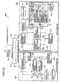
- FIG. 12 is a block diagram showing a radio communication system of a sixth embodiment;
- FIG. 13 shows relation of signal constellation diagrams of received signals, estimation accuracy of reception quality and carrier frequency offset;
- FIG. 14 is a block diagram showing a radio communication system of a seventh embodiment;
- FIG. 15 is a block diagram showing a radio transmitter of an eighth embodiment;
- FIG. 16 is a diagram illustrating a decision method for phase shift amount of the eighth embodiment;
- FIG. 17 is a block diagram showing a radio communication system of a ninth embodiment;
- FIG. 18 is a block diagram showing a radio transmitter of a tenth embodiment;
- FIG. 19 is a diagram illustrating a decision method for transmission power of the tenth embodiment;
- FIG. 20 is a block diagram showing a radio communication system of an eleventh embodiment;
- FIGS. 21A and 21B are diagrams illustrating a decision method for target phase difference and target interference reception quality of the eleventh embodiment;
- FIG. 22 is a diagram showing an information acquisition unit of a twelfth embodiment;
- FIG. 23 is a block diagram showing a radio communication system of a thirteenth embodiment;
- FIG. 24 is a diagram illustrating a decision method for target phase difference and target interference reception quality of the thirteenth embodiment;
- FIG. 25 is a block diagram showing a radio communication system of a fourteenth embodiment;
- FIG. 26 is a block diagram showing a radio communication system of a fifteenth embodiment; and
- FIG. 27 is a block diagram showing a radio communication system of a sixteenth embodiment.
- As shown in FIG. 3, a
radio communication system 100 comprises aradio transmitter 10 and aradio receiver 20. Theradio transmitter 10 transmits a desiredsignal 1 including transmitteddata 15 to theradio receiver 20. Theradio receiver 20 receives the desiredsignal 1 transmitted from theradio transmitter 10, and aninterference signal 2 from aradio station 30. In theradio communication system 100, radio communication between theradio transmitter 10 and theradio receiver 20 are performed. For example, the radio communication between base stations, between access points, between the base station and access point, between the mobile station and base station, between the radio terminal and access point, between the radio stations in the adohoo network, or between the radio stations in the multihop network can be performed. In other words, the base station, the access point, the mobile station, the radio terminal, the radio station in the adohoo network, and the radio station in the multihop network are used as theradio transmitter 10 andradio receiver 20. - In order to simplify the following description, the
radio transmitter 10 is described having a transmission system configuration and theradio receiver 20 having a reception system configuration; however, theradio transmitter 10 may have the configuration of the reception system of theradio receiver 20, and theradio receiver 20 may have the configuration of the transmission system of theradio transmitter 10. - The
radio receiver 20 includes anoscillator 21, aninterference frequency detector 22, atransmission controller 22a, anantenna 23a, a transmission-reoeption separator 23, acoherent detector 24, aninterference canceller 25, a frequency offsetestimator 26, and aninformation signal generator 27. - The
antenna 23a transmits and receives signals. Theantenna 23a transmits, for example, an information signal as a transmission signal, and receives a mixed signal including aninterference signal 2 from theradio station 30 and a desiredsignal 1 from theradio transmitter 10, as a reception signal. The information signal is a signal including control information provided to theradio transmitter 10 from theradio receiver 20. Theradio receiver 20 transmits an offsetinformation signal 3 including a carrier frequency offset estimated by theradio receiver 20, as an information signal. The carrier frequency offset between the carrier frequency of theinterference signal 2 and the carrier frequency of the desiredsignal 1, which are included in the received signal. - The transmission-
reception separator 23 switches over between input and output for a received signal input from theantenna 23a
and a transmission signal output to theantenna 23a, respectively. The transmission-reception separator 23 acquires the offsetinformation signal 3 as a transmission signal from theinformation signal generator 27. The transmission-reception separator 23 inputs the received signal to theinterference frequency detector 22, thetransmission controller 22a, thecoherent detector 24, and the frequency offsetestimator 26. - The
interference frequency detector 22 detects a carrier frequency fc +f of the
interference signal 2. Theinterference frequency detector 22 detects the carrier frequency of theinterference signal 2 when theinterference signal 2 is more than or equal to a predetermined power. The predetermined power is set to a certain appropriate value, which is used to determine whether detection of the carrier frequency of theinterference signal 2 is necessary. The predetermined power may be set to, for example, a certain value that allows theinterference signal 2 to be seen small and also the received signal to be seen approximately equivalent to the desiredsignal 1. Theinterference frequency detector 22 can reduce the control load of theradio transmitter 10 and theradio receiver 20, by detecting the carrier frequency of theinterference signal 2 only when theinterference signal 2 is more than or equal to the predetermined power then omitting transmission of the offsetinformation signal 3 toradio transmitter 10 and compensation for the frequency offset at theradio transmitter 10 when influence from the carrier frequency offset is small. - Specifically, the
transmission controller 22a detects the power of theinterference signal 2, instructs theradio transmitter 10 to halt or start transmission of the desiredsignal 1, and instructs theinterference frequency detector 22 to detect the carrier frequency of theinterference signal 2. Thetransmission controller 22a detects the power of theinterference signal 2 included in the received signal from the transmission-reception separator 23. Thetransmission controller 22a instructs theradio transmitter 10 to halt transmission of the desiredsignal 1 when theinterference signal 2 is more than or equal to the predetermined power. Theantenna 23a receives only theinterference signal 2 while theradio receiver 10 halts transmission of the desiredsignal 1. Therefore, theinterference frequency detector 22 can acquire only theinterference signal 2 as a received signal from the transmission-reception separator 23. - Accordingly, the
transmission controller 22a instructs theinterference frequency detector 22 to detect the carrier frequency of theinterference signal 2 once theradio transmitter 10 has been instructed to halt transmission. Subsequently, thetransmission controller 22a instructs theradio transmitter 10 to resume transmission of the desiredsignal 1. Thetransmission controller 22a instructs by transmitting a halt or a resume instruction to theradio transmitter 10 via the transmission-reception separator 23 and theantenna 23a. - The
interference frequency detector 22 detects the carrier frequency of the received signal from the transmission-reception separator 23. Theinterference frequency detector 22 detects the carrier frequency of the received signal as the carrier frequency of theinterference signal 2 once it has acquired a detection instruction from thetransmission controller 22a. Theinterference frequency detector 22 acquires a detection instruction from thetransmission controller 22a only when theinterference signal 2 is more than or equal to the predetermined power. However, when acquiring a detection instruction from thetransmission controller 22a, transmission of the desiredsignal 1 is halted and theinterference frequency detector 22 acquires only theinterference signal 2 as a received signal from the transmission-reception separator 23. Therefore, by detecting the carrier frequency of the received signal only when the interference frequency detector 22acquires the detection instruction from thetransmission controller 22a, theinterference frequency detector 22 can detect the carrier frequency of theinterference signal 2 only when theinterference signal 2 is more than or equal to the predetermined power. Theinterference frequency detector 22 then inputs the detected carrier frequency of theinterference signal 2 to the frequency offsetestimator 26 and theoscillator 21. - The
interference frequency detector 22 detects the carrier frequency of the received signal as the carrier frequency of the desiredsignal 1 while not acquiring a detection instruction from thetransmission controller 22a. Theinterference frequency detector 22 does not acquire a detection instruction from thetransmission controller 22a when theinterference signal 2 is less than the predetermined power. Therefore, while theinterference frequency detector 22 is not acquiring an instruction, the power of theinterference signal 2 is less than the predetermined power, and the received signal is assumed to be approximately equivalent to the desiredsignal 1. Theinterference frequency detector 22 inputs the detected carrier frequency of the desiredsignal 1 to theoscillator 21. - The
oscillator 21 oscillates at a reference frequency, and inputs it to thecoherent detector 24. Theoscillator 21 acquires the carrier frequency of the received desiredsignal 1 from theinterference frequency detector 22, and oscillates therewith as a reference frequency before detecting the carrier frequency of theinterference signal 2. After having detected the carrier frequency of theinterference signal 2, theoscillator 21 rotates the oscillated reference frequency to the carrier frequency of theinterference signal 2 from theinterference frequency detector 22. - In this embodiment, the
oscillator 21 uses the carrier frequency of the desiredsignal 1 as a reference frequency before detecting the carrier frequency of theinterference signal 2 and transmitting the offsetinformation signal 3. And theoscillator 21 uses the carrier frequency of theinterference signal 2 as the same after the offsetinformation signal 3 has been transmitted. Note that after theoscillator 21 has rotated the oscillated reference frequency to the carrier frequency of theinterference signal 2 detected by theinterference frequency detector 22, theinterference frequency detector 22 may instruct theradio transmitter 10 to resume transmission of the desiredsignal 1. - The
coherent detector 24 synchronously detects the received signal input from the transmission-reception separator 23 based on the reference frequency input from theoscillator 21. Theinterference frequency detector 22 the received signal, which is the signal after theinterference frequency detector 22 has detected the carrier frequency of theinterference signal 2 and transmission of the desiredsignal 1 has resumed, namely, the received signal mixed the desiredsignal 1 and theinterference signal 2. Thecoherent detector 24 inputs the detected received signal to theinterference canceller 25. - The frequency offset
estimator 26 estimates the carrier frequency offsetf, which is the difference between the carrier frequency fc + f of the
interference signal 2 included in the received signal and the carrier frequency fc of the desiredsignal 1 included in the received signal. The frequency offsetestimator 26 acquires the carrier frequency of theinterference signal 2 from theinterference frequency detector 22. In addition, the frequency offsetestimator 26 acquires the received signal from the transmission-reception separator 23. When aninterference signal 2 does not generate from aradio station 30, theradio transmitter 10 notifies theradio receiver 20 of transmission commencement of the desiredsignal 1 and transmits the desiredsignal 1. The signal received by theradio receiver 20 at the time when this transmission commences is almost the desiredsignal 1. Therefore, when having acquired the received signal, which is received at the commencement notice from theradio transmitter 10, the frequency offsetestimator 26 considers that the received signal is the desiredsignal 1, and detects its carrier frequency, and memorizes it. The frequency offsetestimator 26 estimates the carrier frequency offset by calculating the difference between the acquired carrier frequency of theinterference signal 2 and the memorized carrier frequency of the desiredsignal 1. The frequency offsetestimator 26 inputs the estimated carrier frequency offset to theinformation signal generator 27. - The
information signal generator 27 generates an information signal including control information, which is provided to theradio transmitter 10 from theradio receiver 20. Theinformation signal generator 27 generates an offsetinformation signal 3 based on the carrier frequency offsetf, as information signal. The offset information signal may include the carrier frequency offset itself, or may include information decided from the carrier frequency offset. The offset
information signal 3 in this embodiment includes the carrier frequency offset. Theinformation signal generator 27 generates the offsetinformation signal 3 by converting the information including the carrier frequency offset acquired from the frequency offsetestimator 26 to a signal through modulation. Theinformation signal generator 27 inputs the generated offsetinformation signal 3 to the transmission-reception separator 23. In this manner, theinformation signal generator 27 transmits the offsetinformation signal 3 to theradio transmitter 10 via the transmission-reception separator 23 and theantenna 23a. - The
interference canceller 25 generates a replica of the received signal and removes theinterference signal 2 from the received signal. Theinterference canceller 25 comprises apropagation path estimator 25a, adetermination unit 25b, a desiredsignal replica generator 25c, an interferencesignal replica generator 25d, a squaringcircuit 25e, asubtracter 25f, and anadder 25g. - To begin with, the
propagation path estimator 25a estimates the propagation paths for the receivedsignal 1 and theinterference signal 2, and calculates the respective propagation path estimation values. Thepropagation path estimator 25a acquires the difference between an actually receivedsignal 8a and a plurality of receivedsignal replicas 8b from thesubtracter 25f so as to estimate propagation paths using the difference. Thepropagation path estimator 25a inputs the calculated propagation path estimation value for the desiredsignal 1 to the desiredsignal replica generator 25c. Thepropagation path estimator 25a then inputs the calculated propagation path estimation value for theinterference signal 2 to the interferencesignal replica generator 25d. - In addition, the
determination unit 25b generates a plurality of desired signal symbol sequence candidates and interference signal symbol sequence candidates. Thedetermination unit 25b inputs the generated a plurality of desired signal symbol sequence candidates to the desiredsignal replica generator 25c. Thedetermination unit 25b then inputs the generated a plurality of interference signal symbol sequence candidates to the interferencesignal replica generator 25d. - The desired
signal replica generator 25c generates a plurality of desired signal replicas by multiplying the propagation path estimation value for the desiredsignal 1 from thepropagation path estimator 25a by the signal points, which are obtained by modulating the a plurality of desired signal symbol sequence candidates from thedetermination unit 25b. The interferencesignal replica generator 25d generates a plurality of interference signal replicas by multiplying the propagation path estimation value for theinterference signal 2 from thepropagation path estimator 25a by the signal points, which are obtained by modulating the a plurality of interference signal symbol sequence candidates from thedetermination unit 25b. The desiredsignal replica generator 25c and the interferencesignal replica generator 25d input a plurality of generated desired signal replicas and interference signal replicas to theadder 25g. - The
adder 25g adds together the a plurality of desired signal replicas and interference signal replicas acquired from the desiredsignal replica generator 25c and the interferencesignal replica generator 25d, respectively, so as to calculate the sum thereof and generate a plurality of receivedsignal replicas 8b. In this manner, the desiredsignal replica generator 25c, the interferencesignal replica generator 25d, and theadder 25g generate the receivedsignal replicas 8b based on the propagation path estimation value . Theadder 25g inputs the generated a plurality of receivedsignal replicas 8b to thesubtracter 25f. - The
subtracter 25f acquires the actually receivedsignal 8a from thecoherent detector 24 and a plurality of receivedsignal replicas 8b from theadder 25g. Thesubtracter 25f calculates the differences between the actually receivedsignal 8a and a plurality of receivedsignal replicas 8b, and inputs the differences to thepropagation path estimator 25a and the squaringcircuit 25e. The squaringcircuit 25e squares the differences between the receivedsignal 8a and a plurality of receivedsignal replicas 8b, and inputs squared values to thedetermination unit 25b. - The
determination unit 25b determines the desired signal symbol sequence candidate and the interference signal symbol sequence candidate, which allow a minimum squared value of the difference between the actually receivedsignal 8a and a plurality of receivedsignal replicas 8b, and outputs the desired signal components thereof as the received desiredsignal 1. Thedetermination unit 25b can determine the desired signal symbol sequence candidate and the interference signal symbol sequence candidate, which allow a minimum absolute value of the difference between the actually receivedsignal 8a and a plurality of receivedsignal replicas 8b, by determining using the squared value of the difference between the receivedsignal 8a and a plurality of receivedsignal replicas 8b as such. In this manner, thedetermination unit 25b compares the receivedsignal replicas 8b with the actually receivedsignal 8a so as to determine the desired signal components of the receivedsignal replica 8b close to the actually receivedsignal 8a, as the desiredsignal 1. Furthermore, theinterference canceller 25 removes theinterference signal 2 from the receivedsignal 8a acquired from thecoherent detector 24 so as to provide the desiredsignal 1. Thedetermination unit 25b then demodulates the desiredsignal 1, and outputs the receiveddata 15a transmitted from aradio transmitter 10, and received by the radio receiver20. - The transmission-
reception separator 23, theinterference frequency detector 22, thetransmission controller 22a, theoscillator 21, thecoherent detector 24, the frequency offsetestimator 26, theinterference canceller 25, and theinformation signal generator 27 may utilize a circuit performing the above-mentioned functions, for example. - The
radio transmitter 10 comprises anantenna 11a, a transmission-reception separator 11, asignal separator 12, afrequency controller 13, a transmittedsignal generator 14, and atransmission controller 14a. Theantenna 11a transmits and receives signals. Theantenna 11 transmits, for example, the desiredsignal 1 as a transmission signal, and receives an information signal such as the offsetinformation signal 3 as a received signal. The transmission-reception separator 11 switches over between input and output of the transmission signal output to theantenna 11a and the received signal input from theantenna 11a, respectively. The transmission-reception separator 11 acquires the desired signal as a transmission signal from theinformation signal generator 14. The transmission-reception separator 11 inputs the received signal to thesignal separator 12. - The
signal separator 12 separates the offsetinformation signal 3 from within the received signals, and inputs it to thefrequency controller 13. Thesignal separator 12 separates a halt and a resume instruction for transmission of the desiredsignal 1 from within the received signals, and inputs it to thetransmission controller 14a. Thefrequency controller 13 adjusts the carrier frequency of the transmitted desiredsignal 1 to the carrier frequency of theinterference signal 2 based on the carrier frequency offsetf received from the
radio receiver 20. Thefrequency controller 13 acquires the carrier frequency offset from the offsetinformation signal 3. Thefrequency controller 13 controls the carrier frequency by inputting to the transmittedsignal generator 14 a carrierfrequency control signal 4a, which is used to control the carrier frequency of the desired signal based on the carrier frequency offset. - The
transmission controller 14a acquires a halt and a resume instruction for transmission of the desiredsignal 1 from theradio receiver 20 via theantenna 11a and the transmission-reception separator 11. Thetransmission controller 14a instructs the transmittedsignal generator 14 to halt and resume transmission of the desiredsignal 1 in conformity with the acquired instruction. - The transmitted
signal generator 14 generates a desired signal including the transmitteddata 15 as a transmission signal from the transmitteddata 15, and inputs it to the transmission-reception separator 11. The transmittedsignal generator 14 generates a desiredsignal 1 using the carrier wave frequency fc + Δf in conformity with the carrierfrequency control signal 4a. Accordingly, the transmittedsignal generator 14 can generate the desiredsignal 1 of the carrier frequency adjusted to carrier frequency of theinterference signal 2. The transmittedsignal generator 14 transmits the desiredsignal 1 to theradio receiver 20 via the transmission-reception separator 11 and theantenna 11a. - The transmitted
signal generator 14 halts and resumes transmission of the desiredsignal 1 in conformity with the instruction from thetransmission controller 14a. The transmittedsignal generator 14 halts transmission of the desiredsignal 1 without inputting it to the transmission-reception separator 11 when a halt instruction has been acquired from thetransmission controller 14a. Subsequently, the transmittedsignal generator 14 inputs the desiredsignal 1 to the transmission-reception separator 11 so as to resume transmission thereof when having acquired a resume instruction from thetransmission controller 14a. The transmission-reception separator 11, thesignal separator 12, thefrequency controller 13, the transmittedsignal generator 14 and thetransmission controller 14a may utilize a circuit performing the above-mentioned functions. - A procedure for a radio communication method using a
communication system 100 shown in FIG. 3 is described referencing FIG. 4. Theradio transmitter 10 transmits a desired signal 1 (S101). Theradio receiver 20 detects the power of aninterference signal 2 included in the received signal (S102). Theradio receiver 20 instructs theradio transmitter 10 to halt transmission of the desiredsignal 1 when theinterference signal 2 is more than or equal to a predetermined power (S103). Theradio transmitter 10 halts transmission of the desired signal in conformity with the halt instruction (S104). Theradio receiver 20 detects a carrier frequency of theinterference signal 2 while theradio transmitter 10 halts transmission of the desired signal 1 (S105). Theradio receiver 20 instructs theradio transmitter 10 to resume transmission of the desiredsignal 1 after theradio receiver 20 detects the carrier frequency of the interference signal 2 (S106). Theradio transmitter 10 resumes transmission and transmits the desiredsignal 1 in conformity with the instruction from the radio receiver 20 (S107). - After transmission of the desired
signal 1 has resumed, theradio receiver 20 estimates a carrier frequency offsetf based on the memorized carrier frequency of the desired
signal 1 and the detected carrier frequency of the interference signal 2 (S108). Theradio receiver 20 transmits to theradio transmitter 10 an offsetinformation signal 3 including the estimated carrier frequency offset Δf (s109). - After the offset
information signal 3 is transmitted, theradio receiver 20 synchronously detects using the carrier frequency of theinterference signal 2 as a reference frequency (S110). Furthermore, theradio receiver 20 removes theinterference signal 2 from the Synchronously detected received signal, and demodulates the received signal so as to provide the receiveddata 15a. Theradio transmitter 10 controls the carrier frequency of the desiredsignal 1 so as to adjust the carrier frequency of the transmitted desiredsignal 1 to carrier frequency fc +f of the
interference signal 2 based on the carrier frequency offsetf included in the offset information signal 3 (S111). The
radio transmitter 10 then transmits to theradio receiver 20 the desiredsignal 1 with the controlled carrier frequency. - According to the
radio communication system 100,radio transmitter 10,radio receiver 20, and a radio communication method, theradio receiver 20 can estimate the carrier frequency offset. Theradio receiver 20 may generate the offsetinformation signal 3 including the estimated carrier frequency offset. Therefore, theradio receiver 20 can notify theradio transmitter 10 of the carrier frequency offset. - The
radio transmitter 10 may then adjust the carrier frequency of the transmitted desiredsignal 1 to the carrier frequency of theinterference signal 2 based on the notified carrier frequency offset estimated by theradio receiver 20. Accordingly, the carrier frequency offset may be independently compensated on each radio link connected between theradio receiver 20 and theradio transmitter 10. Therefore, aninterference canceller 25 of theradio receiver 20 may remove theinterference signal 2 by following propagation path estimation. Thereby, theradio communication system 100 may enhance the effectiveness of theinterference canceller 25 and improve the frequency utilization efficiency. The carrier frequency offset may be compensated even in a high frequency radio system with a great carrier frequency offset. - The
interference frequency detector 22 detects the carrier frequency of theinterference signal 2 by instructing theradio transmitter 10 to halt transmission of the desiredsignal 1 and receive only theinterference signal 2. Accordingly, theinterference frequency detector 22 may accurately and easily detect the carrier frequency of theinterference signal 2. - As shown in FIG. 5, a
radio communication system 100a comprises aradio transmitter 10a and theradio receiver 20. Theradio transmitter 10a comprises theantenna 11a, the transmission-reception separator 11, thesignal separator 12, thetransmission controller 14a, apower amplifier 161, afrequency converter 162, anoscillator 163, aphase shift calculator 164, abaseband modulator 165, and amultiplier 166. Namely, theradio transmitter 10a shown in FIG. 5 comprises thephase shift calculator 164 and themultiplier 166 in place of thefrequency controller 13 of theradio transmitter 10 shown in FIG. 3, and also comprises thepower amplifier 161, thefrequency converter 162, theoscillator 163 and thebaseband modulator 165 in place of the transmittedsignal generator 14. The same reference numerals are given in FIG. 5 for the substantially same configuration as those in theradio communication system 100 shown in FIG. 3, and a part of the description is omitted. - The
baseband modulator 165 modulates the transmitteddata 15 to be included in the desiredsignal 1 into abaseband signal 5a. Thebaseband modulator 165 inputs thebaseband signal 5a to themultiplier 166. - The
signal separator 12 inputs to thephase shift calculator 164 the offsetinformation signal 3 separated from the received signal. Thephase shift calculator 164 calculates the angular speed 2pf in accordance with the carrier frequency offset from the carrier frequency offset f included in the received offset
information signal 3. As such, the angular speed 2πf is proportional to the carrier frequency offset f. The
phase shift calculator 164 calculates thephase rotation amount 4b 'ej2πft' from the calculated angular speed 2π f. The phase rotation amount is represented by a complex exponential in this manner. The
phase shift calculator 164 then inputs to themultiplier 166 thephase rotation amount 4b 'ej2πfy', which is based on the angular speed 2π f proportional to the carrier frequency offset.
- The
multiplier 166 rotates the phase of thebaseband signal 5a at the angular speed 2πΔf in accordance with the carrier frequency offset by multiplying thebaseband signal 5a by thephase rotation amount 4b 'ej2πft', which is input from the
phase shift calculator 164. Themultiplier 166 inputs to thefrequency converter 162 the phase-shiftedbaseband signal 5b obtained through rotation. - In this manner, the
phase shift calculator 164 inputs to themultiplier 166 thephase rotation amount 4b 'ej2πft' that depends on the carrier frequency offset, and the
multiplier 166 rotates the phase of thebaseband signal 5a at the angular speed 2πΔf that depends on the carrier frequency offset, in conformity with the inputphase rotation amount 4b 'ej2πft'. Thereby, the carrier frequency of the desired
signal 1 is adjusted to carrier frequency of theinterference signal 2. Namely, thephase shift calculator 164 and themultiplier 166 function as a frequency controller that adjusts the carrier frequency of the desiredsignal 1 to carrier frequency of theinterference signal 2 based on the carrier frequency offset. - The
frequency converter 162 converts the center frequency of the phase-shiftedbaseband signal 5b to the desiredsignal 1. Theoscillator 163 oscillates a reference frequency of thefrequency converter 162 and inputs it thereto. Thefrequency converter 162 converts the center frequency of the phase-shiftedbaseband signal 5b using the reference frequency from theoscillator 163. - The carrier frequency of the desired
signal 1 obtained through the conversion by thefrequency converter 162 apparently adjusts to the carrier frequency fc +f of the
interference signal 2, as in the following Equation (1).
frequency converter 162 inputs to thepower amplifier 161 the desiredsignal 1 obtained through the conversion. Thetransmission controller 14a instructs thepower amplifier 161 to halt and resume transmission of the desiredsignal 1. - The
power amplifier 161 amplifies the power of the desiredsignal 1 from thefrequency converter 162. Thepower amplifier 161 inputs the amplified desiredsignal 1 to the transmission-reception separator 11, which then transmits it to theradio receiver 20 via theantenna 11a. Thepower amplifier 161 halts and resumes transmission of the desiredsignal 1 in conformity with the instruction from thetransmission controller 14a. Thepower amplifier 161 halts transmission of the desiredsignal 1 without inputting it to the transmission-reception separator 11 when a halt instruction has been acquired from thetransmission controller 14a. Subsequently, after acquiring a resume instruction from thetransmission controller 14a, thepower amplifier 161 inputs the desiredsignal 1 to the transmission-reception separator 11 so as to resume transmission thereof. - In this manner, the
baseband modulator 165, theoscillator 163, thefrequency converter 162, and the power amplifier function as a transmitted signal generator that generates the desiredsignal 1 from the transmitteddata 15. - According to the
radio transmitter 10a, the carrier frequency of the desiredsignal 1 can apparently adjust to the carrier frequency of theinterference signal 2 by rotating the phase of thebaseband signal 5a at the angular speed 2πf in accordance with the carrier frequency offset f, which is notified from the
radio receiver 10. Thereby, theradio transmitter 10a can easily compensate for the carrier frequency offset. - As shown in FIG. 6, a
radio communication system 100b comprises aradio transmitter 10b and theradio receiver 20. Theradio transmitter 10b comprises theantenna 11a, the transmission-reception separator 11, thesignal separator 12, thetransmission controller 14a, thepower amplifier 161, thefrequency converter 162, theoscillator 163, and anoscillator controller 167. Namely, theradio transmitter 10b shown in FIG. 6 comprises theoscillator controller 167 in place of thefrequency controller 13 of theradio transmitter 10 shown in FIG. 3, and also comprises thepower amplifier 161, thefrequency converter 162, theoscillator 163, and thebaseband modulator 165 in place of the transmittedsignal generator 14. The same reference numerals are given in FIG. 6 for the substantially same configuration as those in theradio communication systems - The
signal separator 12 inputs to theoscillator controller 167 the offsetinformation signal 3 separated from the received signal. Thebaseband modulator 165 inputs to thefrequency converter 162 thebaseband signal 5a obtained by modulating the transmitteddata 15. - The
oscillator controller 167 adjusts the carrier frequency of the desiredsignal 1 to be transmitted to the carrier frequency of theinterference signal 2 by controlling the reference frequency used to convert the center frequency of thebaseband signal 5a through thefrequency converter 162, based on the carrier frequency offset. Based on the carrier frequency offsetf included in the acquired offset
information signal 3, theoscillator controller 167 decides the reference frequency used for conversion such that the carrier frequency of the desiredsignal 1 adjusts to carrier frequency of theinterference signal 2. Theoscillator controller 167 inputs to the oscillator 163 a referencefrequency control signal 4c, which is used to instruct the decided reference frequency. - The
oscillator 163 oscillates with the reference frequency, which is included in the referencefrequency control signal 4c acquired from theoscillator controller 167, and inputs the reference frequency to thefrequency converter 162. Thefrequency converter 162 converts the center frequency of thebaseband signal 5a using the reference frequency acquired from theoscillator 163, so as to make the desiredsignal 1. In this manner, theoscillator controller 167 controls the reference frequency used through thefrequency converter 162 by instructing theoscillator 163 to oscillate with the decided reference frequency. Theoscillator controller 167 functions as a frequency controller that adjusts the carrier frequency of the desiredsignal 1 to be transmitted to the carrier frequency of theinterference signal 2 by controlling the reference frequency based on the carrier frequency offset. Theoscillator controller 167 may utilize a circuit performing the above-mentioned functions. - According to the
radio transmitter 10b, the carrier frequency of the desiredsignal 1 can adjust to the carrier frequency of theinterference signal 2 with higher accuracy by controlling the reference frequency used to convert the center frequency of thebaseband signal 5a, based on the carrier frequency offset. Accordingly, theradio transmitter 10b may compensate for the carrier frequency offset with higher accuracy. Therefore, the remnant carrier frequency offset after the carrier frequency offset has been compensated may be reduced. - As shown in FIG. 7, a
radio communication system 100c comprises theradio transmitter 10 and aradio receiver 20c. Theradio receiver 20 comprises theoscillator 21, theinterference frequency detector 22, thetransmission controller 22a, theantenna 23a, the transmission-reception separator 23, thecoherent detector 24, theinterference canceller 25, a frequency offsetestimator 26c, a rotationspeed measurement unit 28, and theinformation signal generator 27. The same reference numerals are given in FIG. 7 for the substantially same configuration as those in theradio communication systems 100 shown in FIG. 3, and a part of the description is omitted. - The
oscillator 21 acquires the carrier frequency fc + Δf of theinterference signal 2 from theinterference frequency detector 22, oscillating therewith as the reference frequency of thecoherent detector 24. Thecoherent detector 24 synchronously detects the received signal mixed the desiredsignal 1 and theinterference signal 2 using a reference signal input from theoscillator 21, namely the carrier frequency of theinterference signal 2 used as the reference frequency so as to obtain thebaseband signal 5a as the synchronously detected received signal. The signal constellation diagram of signal points 5c of abaseband signal 5a is shown in FIG. 8A. The signal constellation diagram is a diagram showing signal points plotted on a coordinate where the vertical axis represents quadrature (Q) components and the horizontal axis represents in-phase (I) components. The signal points 5c of the baseband signals 5a are observed to rotate around thesignal point 2a of theinterference signal 2 at an angular speed 2πf proportional to the carrier frequency offset f. It should be noted that the
signal point 2a of theinterference signal 2 is actually invisible. Thecoherent detector 24 inputs to theinterference canceller 25 thebaseband signal 5a obtained by synchronously detecting the received signal. - The
interference canceller 25 obtains aresidual signal 6 by removing theinterference signal 2 from thebaseband signal 5a. Theresidual signal 6 includes not only the desiredsignal 1 but noise as well. The signal constellation diagram ofsignal points 6a of theresidual signal 6 is shown in FIG. 8B. Thesignal point 6a of theresidual signal 6 results from subtracting thesignal point 2a of theinterference signal 2 from the signal points 5c of thebaseband signal 5a, and is observed to rotate at the angular speed 2πf proportional to the carrier frequency offset f. Namely, the phase of the
residual signal 6 rotates at the angular speed 2πf. Since the phase of the desired
signal 1 rotates at the angular speed 2πf in this manner, the phase of the
residual signal 6 while noise remains in the desiredsignal 1 also averagely rotates at the angular speed 2πf. The
interference canceller 25 inputs theresidual signal 6 to the rotationspeed measurement unit 28. - The rotation
speed measurement unit 28 measures the rotation speed 2πΔf of the desiredsignal 1 included in the synchronously detected received signal. The rotation speed is the angular speed of signal phase rotation. The rotationspeed measurement unit 28 measures the rotation speed of theresidual signal 6 , which results from removing theinterference signal 2 acquired from theinterference canceller 25. In this manner, the rotationspeed measurement unit 28 may measure the rotation speed of the desiredsignal 1 itself, or measure the rotation speed of theresidual signal 6 while noise remains in the desiredsignal 1. - Furthermore, the rotation
speed measurement unit 28 may measure the rotation speed 2πf of the desired
signal 1 included in the synchronously detected received signal by estimating the rotation speed based on the propagation path estimation value estimated through thepropagation path estimator 25a of theinterference canceller 25. In this case, thepropagation path estimator 25a inputs the propagation path estimation value to the rotationspeed measurement unit 28 rather than theinterference canceller 25 inputs theresidual signal 6 to the rotationspeed measurement unit 28. The rotationspeed measurement unit 28 may accurately measure the rotation speed from the propagation path estimation value especially after the carrier frequency offset has been sufficiently reduced. The rotationspeed measurement unit 28 inputs the measured rotation speed to the frequency offsetestimator 26c. - The frequency offset
estimator 26c estimates the carrier frequency offset based on the rotation speed of the desiredsignal 1 included in the received signal. The frequency offsetestimator 26c may estimate the carrier frequency offsetf through calculation based on the rotation speed 2π f acquired from the rotation
speed measurement unit 28. The frequency offsetestimator 26c inputs the estimated carrier frequency offset to theinformation signal generator 27. The frequency offsetestimator 26c may estimate based on the rotation speed of the desiredsignal 1 itself, or estimate based on the rotation speed of theresidual signal 6 while noise remains in the desiredsignal 1. The frequency offsetestimator 26c and the rotationspeed measurement unit 28 may utilize a circuit performing the above-mentioned functions. - Note that it is preferable that the
transmission controller 22a instructs theradio transmitter 10 to transmit a desiredsignal 1 configured with a single symbol with sufficiently little transmission power when instructing theradio transmitter 10 to resume transmission of the desiredsignal 1. Accordingly, the transmittedsignal generator 14 of theradio transmitter 10 resumes transmission of the desiredsignal 1 configured with a single symbol with sufficiently little transmission power based on the instruction from thetransmission controller 14a in conformity with the instruction from theradio receiver 20c. Hereby, since the desiredsignal 1 is transmitted with sufficiently little transmission power, theinterference canceller 25 may easily generate interference signal symbol sequence candidates and easily generate interference signal replicas. Therefore, theinterference canceller 25 may easily remove theinterference signal 2. - Furthermore, in the case where control of the carrier frequency continues and the carrier frequency offset has been reduced, it is preferable that the
transmission controller 22a instruct theradio transmitter 10 to gradually increase the transmission power of the desiredsignal 1. Accordingly, the transmittedsignal generator 14 of theradio transmitter 10 transmits the desiredsignal 1 while gradually increasing the transmission power. As a result, reception quality of the desired signal increases, and the estimation accuracy of the frequency offsetestimator 26c improves. - In addition, the frequency offset
estimator 26c may pre-memorize the symbol sequence of the desiredsignal 1, and estimate the carrier frequency offset using the memorized symbol sequence. As a result, the frequency offsetestimator 26c may estimate the carrier frequency offset with high accuracy. Furthermore, in this case, it is unnecessary for thetransmission controller 22a to instruct to decrease the transmission power of the desiredsignal 1. In addition, when measuring the rotation speed 2πΔf of the desiredsignal 1 based on the propagation path estimation value, the rotationspeed measurement unit 28 may measure the rotation speed with high accuracy even if the transmission power of the desiredsignal 1 is large. Furthermore, also in this case, it is unnecessary for thetransmission controller 22a to instruct to decrease the transmission power of the desiredsignal 1. - A procedure for a radio communication method using the
communication system 100c shown in FIG. 7 is described referencing FIG. 9. Theradio transmitter 10 and theradio receiver 20c perform steps (S201) through (S205). Steps (S201) through (S205) are the same as steps (S101) through (S105) shown in FIG. 4. Theradio receiver 20c changes the reference frequency used for synchronized detection to the carrier frequency fc + Δf of theinterference signal 2 detected in step (S205) (S206). Subsequently, theradio receiver 20c instructs theradio transmitter 10 to resume transmission of the desired signal 1 (S207). Theradio transmitter 10 resumes transmission and transmits the desiredsignal 1 in conformity with the instruction from theradio receiver 20c (S208). - After transmission of the desired
signal 1 is resumed, theradio receiver 20c synchronously detects the received signal including the desiredsignal 1 and theinterference signal 2 using the carrier frequency of theinterference signal 2 as the reference frequency so as to obtain thebaseband signal 5a. Theradio receiver 20c then obtains theresidual signal 6 by removing theinterference signal 2 from thebaseband signal 5a (S209). Theradio receiver 20c measures the rotation speed 2πf of the
residual signal 6 as the rotation speed of the desiredsignal 1. Theradio receiver 20c estimates the carrier frequency offsetf based on the measured rotation speed 2π f (S210). The
radio receiver 20c transmits to theradio transmitter 10 an offsetinformation signal 3 including the estimated carrier frequency offsetf (S211). Based on the carrier frequency offset f included in the offset
information signal 3, theradio transmitter 10 controls the carrier frequency of the desiredsignal 1 by adjusting the carrier frequency of the transmitted desiredsignal 1 to the carrier frequency fc + Δf of the interference signal 2 (S212). Theradio transmitter 10 then transmits to theradio receiver 20c the carrier frequency-controlled desiredsignal 1. -
Such radio receiver 20c may estimate the carrier frequency offset by measuring the rotation speed of the desiredsignal 1 included in the received signal itself, or the rotation speed of theresidual signal 6 while noise remains in the desiredsignal 1. As a result, the carrier frequency offset may be independently compensated on each radio link connected between theradio receiver 20c and theradio transmitter 10. - As shown in FIG. 10, a
radio communication system 100d comprises theradio transmitter 10 and aradio receiver 20d. Theradio receiver 20d comprises theoscillator 21, theinterference frequency detector 22, thetransmission controller 22a, theantenna 23a, the transmission-reception separator 23, thecoherent detector 24, theinterference canceller 25, the frequency offsetestimator 26, aninformation signal generator 27c and aquality measurement unit 29. The same reference numerals are given in FIG. 10 for the substantially same configuration as those in theradio communication systems 100 shown in FIG. 3, and a part of the description is omitted. - The transmission-
reception separator 23 inputs a received signal to thequality measurement unit 29. Thequality measurement unit 29 measures the reception quality of the received signal. Thequality measurement unit 29 measures as a reception quality the carrier-to-interference power ratio (CIR), signal-to-interference power ratio (SIR), carrier-to-noise power ratio (CNR) and the like for the received signal. Thequality measurement unit 29 may also measure as the reception quality those that represent the quality of the received signal such as the power ratio of the received signal or the desired signal to theinterference signal 2 or noise. It is especially preferable that thequality measurement unit 29 measures the CNR. Thequality measurement unit 29 measures the reception quality of the received signal from thecoherent detector 24. Thequality measurement unit 29 inputs the measured reception quality to theinformation signal generator 27c. - The
information signal generator 27c makes a determination of whether to control the carrier frequency based on the measured reception quality of the received signal. Theinformation signal generator 27c determines whether to control the carrier frequency by comparing the measured reception quality with the threshold of the reception quality, which is used for the determination of whether to control. Theinformation signal generator 27c then decides whether to generate an offsetinformation signal 3 based on the determination result. Namely, theinformation signal generator 27c decides whether to generate the offsetinformation signal 3 and transmits it to theradio transmitter 10. Alternatively, theinformation signal generator 27c decides the information to be included in the offsetinformation signal 3 based on the determination result. The information to be included in the offsetinformation signal 3 may be the carrier frequency offset, comparison results between the threshold and the measured reception quality, the determination result of whether to control the carrier frequency, or the like. It is preferable that theinformation signal generator 27c determine utilizing the measured values of the CNR and threshold of the CNR. - The
information signal generator 27c presets and memorizes the threshold of the reception quality, then compares the memorized threshold with the measured reception quality. The greater the reception quality of the received signal, the more the estimation accuracy of the carrier frequency offset improves. For example, in the case of a large noise power and a low CNR, there is concern of degradation in estimation accuracy of the carrier frequency offset due to noise power. Therefore, the threshold of the reception quality should be a certain value, which the carrier frequency offsets can be estimated with the high accuracy and the carrier frequency of the desiredsignal 1 can be controlled based on the carrier frequency offset with the high accuracy, due to high reception quality in the case of using more than or equal to the value. - The
information signal generator 27c determines to control the carrier frequency if the measured reception quality is more than or equal to the threshold. Theinformation signal generator 27c then decides to generate the offsetinformation signal 3 and transmit it to theradio transmitter 10 based on the determination result. In this case, theinformation signal generator 27c generates the offsetinformation signal 3 by modulating the information including the carrier frequency offset acquired from the frequency offsetestimator 26 into a signal. Theinformation signal generator 27c transmits the generated offsetinformation signal 3 to theradio transmitter 10 via the transmission-reception separator 23 and theantenna 23a. - Meanwhile, the
information signal generator 27c determines not to control the carrier frequency if the measured reception quality is less than the threshold. Theinformation signal generator 27c then decides not to generate the offsetinformation signal 3 and not transmit it to theradio transmitter 10 based on the determination result. In this case, theinformation signal generator 27c discards the carrier frequency offset acquired from the frequency offsetestimator 26, and does not generate the offsetinformation signal 3. - The
radio transmitter 10 controls the carrier frequency of the desiredsignal 1 based on the carrier frequency offset included in the offsetinformation signal 3 when the offsetinformation signal 3 has been received. Theradio transmitter 10 does not control the carrier frequency of the desiredsignal 1 based on the carrier frequency offset when the offsetinformation signal 3 has not been received. - Alternatively, in the case where the measured reception quality value is more than or equal to the threshold, the
information signal generator 27c determines to control the carrier frequency, and decides that the information to be included in the offsetinformation signal 3 is the estimated carrier frequency offset acquired from the frequency offsetestimator 26. Meanwhile, in the case where the measured reception quality value is less than the threshold, theinformation signal generator 27c determines to control the carrier frequency, and decides that the information to be included in the offsetinformation signal 3 is carrier frequency offset '0', regardless of the carrier frequency offset estimated by the frequency offsetestimator 26. Theinformation signal generator 27c then generates the offsetinformation signal 3 by modulating the information including the determined carrier frequency offset into a signal. Theinformation signal generator 27c transmits the generated offsetinformation signal 3 to theradio transmitter 10 via the transmission-reception separator 23 and theantenna 23a. - The
information signal generator 27c may generate the offsetinformation signal 3 including not only the carrier frequency offset, but the comparison results between the threshold and the measured reception quality, and the determination result of whether to control the carrier frequency as well. For example, it may generate an offsetinformation signal 3 including the information indicating that the measured reception quality is less than the threshold as the comparison result, and the estimated carrier frequency offset. - The
radio transmitter 10 controls the carrier frequency of the desiredsignal 1 based on the estimated carrier frequency offset included in the offsetinformation signal 3, when the offsetinformation signal 3 including the estimated carrier frequency offset has been received. Thefrequency controller 13 of theradio transmitter 10 controls the carrier frequency of the desiredsignal 1 in conformity with a carrier frequency offset '0' even when the offsetinformation signal 3 with carrier frequency offset '0' has been received. As a result, since there is no carrier frequency offset needing compensation, effective compensation for the carrier frequency offset is not performed. - A transmission procedure for a radio communication method using the
communication system 100d shown in FIG. 10 is described referencing FIG. 11A. Theradio receiver 20d measures the reception quality of a received signal (S301). Theradio receiver 20d determines whether to control the carrier frequency by comparing the measured reception quality with the threshold of the reception quality (S302). In the case where the measured reception quality value is more than or equal to the threshold in step (S302), theradio receiver 20d determines to control the carrier frequency, generates an offsetinformation signal 3, and transmits it to the radio transmitter 10 (S303). Theradio receiver 20d then returns to step (S301), and repeats processing. Meanwhile, in the case where the measured reception quality is less than the threshold in step (S302), theradio receiver 20d determines not to control the carrier frequency, and does not generate an offsetinformation signal 3. Theradio receiver 20d then returns to step (S301), and repeats processing. - Another transmission procedure for an offset information signal in the radio communication method using the
communication system 100d shown in FIG. 10 is described referencing FIG. 11B. Theradio receiver 20d measures the reception quality of a received signal (S401). Theradio receiver 20d determines whether to control the carrier frequency by comparing the measured reception quality with the threshold of the reception quality (S402). In the case where the measured reception quality is more than or equal to the threshold in step (S402), theradio receiver 20d determines to control the carrier frequency, generates an offsetinformation signal 3 including the carrier frequency offset estimated by the frequency offsetestimator 26, and transmits it to the radio transmitter 10 (S403) . Theradio receiver 20d then returns to step (S401), and repeats the processing. Meanwhile, in the case where the measured reception quality is less than the threshold in step (S402), theradio receiver 20d determines not to control the carrier frequency, generates an offsetinformation signal 3 including the carrier frequency offset '0', and transmits it to the radio transmitter 10 (S404). Theradio receiver 20d then returns to step (S401), and repeats the processing. - According to the
radio communication system 100d,radio receiver 20d and radio communication method, the offsetinformation signal 3 including the estimated carrier frequency offset may be transmitted to theradio transmitter 10 only when the reception quality of the received signal is high and the carrier frequency offset can be estimated with high accuracy. Therefore, only when the carrier frequency offset is highly accurate, theradio transmitter 10 can control the carrier frequency of the desiredsignal 1 based on the carrier frequency offset. In other words, theradio communication system 100d may control such that the carrier frequency offset is not effectively compensated in the case of low reception quality, and the carrier frequency offset is effectively compensated only in the case of high reception quality, which is done by not having an offsetinformation signal 3 transmitted or transmitting the offsetinformation signal 3 including carrier frequency offset '0' in the case of low reception quality, whereas transmitting the offsetinformation signal 3 or the estimated carrier frequency offset only in the case of high reception quality. As a result, for example, carrier frequency offset compensation may be avoided in the case where the noise power is large, the CNR is low, and the estimation accuracy of the carrier frequency offset has degraded due to the noise power. Accordingly, theradio communication system 100d can compensate for the carrier frequency offset with higher accuracy. - As shown in FIG. 12, a
radio communication system 100e comprises theradio transmitter 10 and aradio receiver 20e. Theradio receiver 20e comprises theoscillator 21, theinterference frequency detector 22, thetransmission controller 22a, theantenna 23a, the transmission-reception separator 23, thecoherent detector 24, theinterference canceller 25, the frequency offsetestimator 26, theinformation signal generator 27c, thequality measurement unit 29, and a threshold decision unit 29e. The same reference numerals are given in FIG. 12 for the substantially same configuration as those in theradio communication systems 100 shown in FIG. 3, and a part of the description is omitted. - The transmission-
reception separator 23 also inputs to the threshold decision unit 29e. The threshold decision unit 29e decides the threshold of the reception quality, which is used for determining whether to control the carrier frequency of the desiredsignal 1. It is preferable that the threshold decision unit 29e determines the threshold of the reception quality based on the modulation method used for the received signal from the transmission-reception separator 23. - In the case where the number of multi-value used for modulating the desired
signal 1 and/or theinterference signal 2 is large, the signal points of the desiredsignal 1 and theinterference signal 2 are easily overlapped, an erroneous determination of the desiredsignal 1 is easily made, and estimation accuracy of the carrier frequency offset is easily degraded. Therefore, estimating the carrier frequency offset with high accuracy in the case of low reception quality becomes difficult. Accordingly, the threshold decision unit 29e decides the threshold of the reception quality to be a large value when the number of multi-value used for modulating the desiredsignal 1 or theinterference signal 2, which is included in the received signal is large, and compensates for the carrier frequency offset only when the reception quality is high. - Meanwhile, in the case where the number of multi-value used for modulating the desired
signal 1 or theinterference signal 2 is small, the signal points of the desiredsignal 1 and theinterference signal 2 do not overlap, the desiredsignal 1 may be determined without error, and estimation accuracy of the carrier frequency offset improves. Therefore., the carrier frequency offset may be estimated with high accuracy even if the reception quality is low. Accordingly, the threshold decision unit 29e decides the threshold of the reception quality to be a small value when the number of multi-value used for modulating the desiredsignal 1 or theinterference signal 2, which is included in the received signal is small, and compensates for the carrier frequency offset even if the reception quality is low. - For example, FIG. 13 presents signal constellation diagrams 7a through 7c for received signals when the modulation method for the desired
signal 1 and theinterference signal 2 is quadrature phase shift keying (QPSK) having the number of multi-value 4, and signal constellation diagrams 7d through 7f for received signals when the modulation method for either one of the desiredsignal 1 or theinterference signal 2 is QPSK, and the other modulation method is 16 quadrature amplitude modulation (QAM) having the number of multi-value is 16. Further towards signal constellation diagram 7c from signal constellation diagram 7a and also further towards signal constellation diagram 7f from signal constellation diagram 7d, reception quality increases and estimation accuracy of the carrier frequency offset increases. - For example, the closer to signal constellation diagrams 7c and 7f when the noise power is low and reception quality is high, the signal points of the received signals do not overlap, the received signal may be determined without error, and estimation accuracy of the carrier frequency offset is higher. Furthermore, overlapping of signal points of the received signals and degradation in estimation accuracy of the carrier frequency offset is easier with the group of signal constellation diagrams 7d through 7f in the case of a large number of the multi-value used for modulation rather than with the signal constellation diagrams 7a through 7c in the case of a small number of the multi-value.
- Therefore, in the case where the received signal modulated with the 4-value modulation method, the threshold decision unit 29e decides to compensate for the carrier frequency offset when the signal constellation diagrams 7b and 7c in which signal points do not easily overlap are obtained. The threshold decision unit 29e then decides the threshold of the reception quality (for example, CNR) to be a minimum value 'X' for the reception quality that can be obtained from signal constellation diagrams 7b and 7c, or a value exceeding the minimum value 'X'. Furthermore, in the case where the received signal modulated with the 16-value modulation method, the threshold decision unit 29e decides to compensate for the carrier frequency offset when the signal constellation diagram 7f in which signal points do not easily overlap is obtained. The threshold decision unit 29e then decides the threshold of the reception quality to be a minimum value ' Y' for the reception quality that can be obtained from signal constellation diagram 7f, or a value exceeding the minimum value 'Y'.
- In addition, even when the
radio receiver 20e already knows the symbol sequence of the desiredsignal 1, theradio receiver 20e may accurately estimate the carrier frequency offset through utilization of the known symbol sequence. Therefore, the carrier frequency offset may be estimated with sufficiently high accuracy even if the threshold of the reception quality is set even lower. Accordingly, the threshold decision unit 29e may decide the threshold of reception quality in the case where theradio receiver 20e receives a desiredsymbol 1 with an unknown symbol sequence (hereinafter, referred to as 'normal threshold'), and threshold of reception quality in the case where theradio receiver 20e receives a desiredsymbol 1 with a known symbol sequence (hereinafter, referred to as 'known signal threshold'). The threshold decision unit 29e may decide a known signal threshold that is lower than the normal threshold. - For example, the threshold decision unit 29e memorizes the symbol sequence of a pilot signal, and when the symbol sequence of a pilot signal included in the received signal from the transmission-
reception separator 23 adjusts the symbol sequence of the memorized pilot signal, the received signal is determined to be known at theradio receiver 20e, and is determined to be unknown when they does not adjust. The threshold decision unit 29e then detects the modulation method used for the received signal, and decides the threshold of the reception quality based on the detection result and the determination result of whether it is a received signal with a known symbol sequence. - The threshold decision unit 29e inputs the decided threshold of the reception quality to the
information signal generator 27c. Theinformation signal generator 27c makes a determination of whether to control the carrier frequency by comparing the measured reception quality acquired from thequality measurement unit 29 with the threshold of the reception quality acquired from the threshold decision unit 29e. - According to the
radio receiver 20e, the threshold of the reception quality is decided to be a high value when the number of multi-value modulation used for the desiredsignal 1 or theinterference signal 2, which is included in the received signal, is large, and highly accurate estimation of the carrier frequency offset is difficult if the reception quality is low, and can compensate for the carrier frequency offset only when the reception quality is high. Meanwhile, theradio receiver 20e decides the threshold for the reception quality to be a low value when the number of multi-value modulation is small and highly accurate estimation of the carrier frequency offset is possible even if the reception quality is low, and can compensate for the carrier frequency offset even if the reception quality is low. Furthermore, theradio receiver 20e may decide the normal threshold or the known signal threshold depending on whether the symbol sequence of the received signal is known. As a result, theradio communication system 100d can compensate for the carrier frequency offset with higher accuracy according to the communication conditions. Furthermore, the remnant carrier frequency offset after carrier frequency offset compensation may be reduced. - As shown in FIG. 14, a
radio communication system 200 comprises aradio transmitter 210 and aradio receiver 220. Theradio receiver 220 comprises theoscillator 21, theantenna 23a, the transmission-reception separator 23, thecoherent detector 24, theinterference canceller 25, aninformation signal generator 227, an interferencequality measurement unit 291, and a phasedifference measurement unit 292. The same reference numerals are given for the substantially same configuration as those in theradio receiver 20 shown in FIG. 3, and a part of the description is omitted. - The
coherent detector 24 synchronously detects a received signal from the transmission-reception separator 23 based on the reference frequency input from theoscillator 21. Thecoherent detector 24 inputs the detected received signal to theinterference canceller 25, the interferencequality measurement unit 291, and the phasedifference measurement unit 292. - The phase
difference measurement unit 292 measures the phase difference between a desiredsignal 1 and aninterference signal 2. The phasedifference measurement unit 292 measures the phase difference between the desiredsignal 1 and theinterference signal 2, which are included in the received signal from thecoherent detector 24. For example, the phasedifference measurement unit 292 may measure the phase difference through utilization of a pilot symbol. The phasedifference measurement unit 292 inputs the measured phase differences to theinformation signal generator 227. - The interference
quality measurement unit 291 measures the interference reception quality, which indicates the influence of an interference signal on the received signal. Everything, which is capable of indicating the influence of the interference signal on the received signal may be used as an interference reception quality. CIR and SIR for received signal, interference signal power, the power ratio of the desiredsignal 1 or received signal to theinterference signal 2 and noise, or the power ratio of the received signal to theinterference signal 2 or the like may be used for the interference reception quality. Note that it is preferable that the interferencequality measurement unit 291 measures the CIR as the interference reception quality. The interferencequality measurement unit 291 measures the interference reception quality of the received signal from thecoherent detector 24. The interferencequality measurement unit 291 inputs the measured interference reception quality to theinformation signal generator 227. - The
information signal generator 227 generates a measured information signal 203 including the measured phase difference between the desiredsignal 1 and theinterference signal 2, and the measured interference reception quality of the received signal, as an information signal. Theinformation signal generator 227 generates the measured information signal 203 by modulating the information including the measured phase difference acquired from the phasedifference measurement unit 292 and the measured interference reception quality acquired from the interferencequality measurement unit 291, into signals. Theinformation signal generator 227 inputs the generated measured information signal 203 to the transmission-reception separator 23. In this manner, theinformation signal generator 227 transmits the measured information signal 203 to theradio transmitter 210 via the transmission-reception separator 23 and theantenna 23a. - The
radio transmitter 210 comprises theantenna 11a, the transmission-reception separator 11, thesignal separator 12, aphase controller 171, amodulator 172, and a variable-phase shifter 174. The same reference numerals are given for the substantially same configuration as those in theradio transmitter 10 shown in FIG. 3, and a part of the description is omitted. - The
antenna 11a receives a measuredinformation signal 203. Thesignal separator 12 separates the measured information signal 203 from within the received signal input from the transmission-reception separator 11, and inputs it to thephase controller 171. Thephase controller 171 controls the phase of a desiredsignal 1 to be transmitted by theradio transmitter 210. Thephase controller 171 controls the phase of the desiredsignal 1 based on the measured phase difference and the measured interference reception quality, which are included in the measuredinformation signal 203. - Here, there is a fixed relationship among the phase difference between the desired
signal 1 and theinterference signal 2, the interference reception quality of the received signal, and the minimum distance between the signal points of the received signals represented in a signal constellation diagram (hereinafter, referred to as 'minimum inter-signal point distance'). For example, the following Equation (2) is established: where '' and ' ' denote unit vectors representing two signal points of the received signal, 'Dz' denotes the minimum inter-signal point distance between those two signal points, ' θ' denotes the phase difference, and 'C' denotes the interference reception quality. CIR(dB) is used as the interference reception quality 'C' in the Equation (2).

- Therefore, the relationship among phase difference, interference reception quality, and minimum inter-signal point distance may be calculated. The
phase controller 171 controls the phase of a transmitted desired signal based on the relationship among the phase difference between the desiredsignal 1 and theinterference signal 2, the interference reception quality of the received signal and the minimum inter-signal point distance of the received signal, and the measured phase difference and the measured interference reception quality. Hereinafter, minimum inter-signal point distance to be targeted is referred to as 'target minimum inter-signal point distance'. Thephase controller 171 controls the phase of the desiredsignal 1 based on the measured interference reception quality, so as to become a necessary phase difference for providing the target minimum inter-signal point distance with that interference reception quality. The target minimum inter-signal point distance may be set to the feasible maximum value with that interference reception quality, or it may be set to a feasible large value with that interference reception quality. Note that the distance between signal points, which are plotted on a coordinate with a Q and an I component and represent the unit vectors obtained by modulating the desiredsignal 1 and theinterference signal 2, is used as the inter-signal point distance. - Based on the measured interference reception quality, the
phase controller 171 calculates a necessary phase difference for making the minimum inter-signal point distance of the received signal equal to the target minimum inter-signal point distance (hereinafter, referred to as 'target phase difference'). For example, thephase controller 171 may calculate the target phase difference using the above-given Equation (2), or may rotate the phase of the desiredsignal 1 with the measured interference reception quality so as to obtain the relationship between the minimum inter-signal point distance and the phase difference and then calculate a phase difference that allows the minimum inter-signal point distance to be the target minimum inter-signal point distance, as the target phase difference. The target phase difference may be a necessary minimum phase difference for obtaining the target minimum inter-signal point distance, or it may be a necessary phase difference for obtaining one that is more than the target minimum inter-signal point distance, so long as it is a phase difference allowing the minimum inter-signal point distance of the received signal to be the target minimum inter-signal point distance. - The
phase controller 171 decides a necessary phase shift amount of the desiredsignal 1 for making the phase difference between the desiredsignal 1 and theinterference signal 2 at theradio receiver 220 equal to the target phase difference, based on the measured phase difference and the calculated target phase difference. Thephase controller 171 controls the phase of the transmitted desiredsignal 1 by inputting aphase control signal 4d used to control the phase of the desiredsignal 1 to the variable-phase shifter 174. Thephase controller 171 generates thephase control signal 4d including an instruction for rotating the phase of the desiredsignal 1 by just the decided phase shift amount, and inputs it to the variable-phase shifter 174. Thephase controller 171 then makes the variable-phase shifter 174 rotate the phase of the desiredsignal 1. Thephase controller 171 preferably controls the phase of the desiredsignal 1 using the feasible maximum value with the interference reception quality as a target minimum inter-signal point distance so that the minimum inter-signal point distance can be the feasible maximum value. In this manner, thephase controller 171 functions as a controller that controls at least one of the phase and transmission power of a transmitted desiredsignal 1 based on the measured phase difference and the measured interference reception quality. - The
modulator 172 modulates the transmitteddata 15 into a desiredsignal 1, inputting it to the variable-phase shifter 174. The variable-phase shifter 174 controls the phase of the desiredsignal 1 acquired from themodulator 172, based on thephase control signal 4d acquired from thephase controller 171. The variable-phase shifter 174 rotates the phase of the desiredsignal 1 acquired from themodulator 172 by just the phase shift amount included in thephase control signal 4d. The variable-phase shifter 174 then inputs the phase-controlled desiredsignal 1 to the transmission-reception separator 11 and transmits it to theradio receiver 220 via theantenna 11a. - According to the
radio communication system 200,radio transmitter 210, andradio receiver 220, theradio transmitter 210 can control the phase of a transmitted desired signal based on the measured phase difference and the measured interference reception quality of the received signal at theradio receiver 220. Specifically, thephase controller 171 controls the phase of the transmitted desiredsignal 1 based on the relationship among the phase difference between the desiredsignal 1 and theinterference signal 2, the interference reception quality of the received signal and the minimum inter-signal point distance of the received signal, and the measured phase difference and the measured interference reception quality. Therefore, theradio communication system 200 can distribute the signal points of the received signals when plotting those signal points. Accordingly, theinterference canceller 25 in theradio receiver 220 can reduce erroneous determination due to the signal points of the received signals being close to each other and output an appropriate desiredsignal 1, so that theinterference signal 2 can be effectively removed. As a result, theradio communication system 200 may enhance the effectiveness of theinterference canceller 25 and improve the frequency utilization efficiency. - Particularly, the
phase controller 171 can distribute the signal points of the received signals over a wide signal area by controlling the phase of the desiredsignal 1 to a maximize value at the minimum inter-signal point distance. Accordingly, theradio transmitter 210 can output an appropriate desiredsignal 1 by more reliably avoiding erroneous determination, and can enhance the effectiveness of theinterference canceller 25. - In the
radio communication system 200 shown in FIG. 14, aradio transmitter 210a shown in FIG. 15 may be used in place of theradio transmitter 210. Theradio transmitter 210a comprises theantenna 11a, the transmission-reception separator 11, thesignal separator 12, thephase controller 171, themodulator 172, the variable-phase shifter 174, and aninformation acquisition unit 176. The same reference numerals are given for the substantially same configuration as those in theradio transmitter 210 shown in FIG. 14, and a part of the description is omitted. In addition, FIG. 16 illustrates a decision method for the phase shift amount. - The
signal separator 12 inputs a measured information signal 203 to thephase controller 171 and theinformation acquisition unit 176. Theinformation acquisition unit 176 acquires a target phase difference based on the measured interference reception quality. Theinformation acquisition unit 176, as shown in FIG. 16, comprises a corresponding table holding information of the relationship between the interference reception qualities of the received signal and target phase differences. In this manner, theinformation acquisition unit 176 memorizes that relationship in advance. The corresponding table 176a holds the target phase difference θtg for every interference reception quality at fixed intervals. The corresponding table 176a may be created by finding the relationship between interference reception quality obtained using the above-given Equation (2) and target phase difference, or may be created by rotating the phase of the desiredsignal 1 with various interference reception quality values, finding the relationship between the minimum inter-signal point distance and a phase difference, and calculating the phase difference as the target phase difference that allows the minimum inter-signal point distance to be the target minimum inter-signal point distance. - In this embodiment, CIR is used as the interference reception quality. The
information acquisition unit 176 acquires a measured interference reception quality 'CIR = 1.8 (dB)' from the measuredinformation signal 203. Theinformation acquisition unit 176 acquires a target phase difference 'θtg - θ 3' corresponding to the interference reception quality closest to the measured interference reception quality 'CIR = 1.8 (dB)' from the corresponding table 176a, by referencing the interference reception quality (CIR) given in the corresponding table 176a and the measured interference reception quality. Theinformation acquisition unit 176 inputs the acquired target phase difference 'θtg = θ 3' to thephase controller 171. - The
phase controller 171 acquires the measured information signal 203 from thesignal separator 12. Thephase controller 171 acquires the target phase difference 'θtg = θ 3' from theinformation acquisition unit 176. Thephase controller 171 acquires the measured phase difference 'θa' from the measuredinformation signal 203. Thephase controller 171 decides a necessary amount of phase shift of the desiredsignal 1 for making the phase difference between the desiredsignal 1 and theinterference signal 2 at theradio receiver 220 equal to the target phase difference, based on the measured phase difference acquired from the measured information signal 203 and the target phase difference acquired from theinformation acquisition unit 176. Thephase controller 171 decides the phase shift amount by subtracting the measured phase difference 'θa' from the target phase difference 'θtg = θ3'. Thephase controller 171 acquires the target phase difference from theinformation acquisition unit 176 in this manner without calculating it by itself. - According to the
radio transmitter 210a, the control load on thephase controller 171 is reduced since theinformation acquisition unit 176 acquires the target phase difference. Furthermore, theinformation acquisition unit 176 holds the corresponding table 176a holding information of the relationship between the interference reception qualities of the received signal and the target phase differences, and acquires the target phase difference from the corresponding table 176a based on the measured interference reception quality. As a result, theinformation acquisition unit 176 may quickly acquire an appropriate target phase difference. - As shown in FIG. 17, a
radio communication system 300 comprises aradio transmitter 310 and theradio receiver 220. Theradio transmitter 310 comprises theantenna 11a, the transmission-reception separator 11, thesignal separator 12, atransmission power controller 173, themodulator 172, and avariable amplifier 175. The same reference numerals are given for the substantially same configuration as those in theradio communication system 200 shown in FIG. 14, and a part of the description is omitted. - The
antenna 11a receives a measuredinformation signal 203. Thesignal separator 12 separates the measured information signal 203 from within the received signals input from the transmission-reception separator 11, and inputs it to thetransmission power controller 173. Thetransmission power controller 173 controls the transmission power of a desiredsignal 1 to be transmitted by theradio transmitter 310. Thetransmission power controller 173 controls the transmission power of the desiredsignal 1 based on the measured phase difference included in the measured information signal 203 and the measured interference reception quality. - The
transmission power controller 173 controls the transmission power of the transmitted desired signal based on the relationship among the phase difference between the desiredsignal 1 and theinterference signal 2, the interference reception quality of the received signal and the minimum inter-signal point distance of the received signal, and the measured phase difference and the measured interference reception quality. Thetransmission power controller 173 controls the transmission power of the desiredsignal 1 based on the measured phase difference so as to become the necessary interference reception quality for obtaining the target minimum inter-signal point distance with that phase difference. The target minimum inter-signal point distance may be set to the feasible maximum value with that phase difference, or it may be set to a feasible large value with that phase difference. - Based on the measured phase difference, the
transmission power controller 173 calculates the necessary interference reception quality for making the minimum inter-signal point distance of the received signal equal to the target minimum inter-signal point distance (hereinafter, referred to as 'target interference reception quality'). For example, thetransmission power controller 173 may calculate the target interference reception quality using the above-given Equation (2), or may vary the transmission power of the desiredsignal 1 based on the measured phase difference, so as to obtain the relationship between the minimum inter-signal point distance and the transmission power and then calculate an interference reception quality that allows the minimum inter-signal point distance to be the target minimum inter-signal point distance, as the target interference reception quality. The target interference reception quality may be the minimum interference reception quality for obtaining the target minimum inter-signal point distance, or it may be an interference reception quality for an inter-signal point distance more than the target minimum inter-signal point distance, so long as it is an interference reception quality allowing the minimum inter-signal point distance of the received signal to equal to the target minimum inter-signal point distance. - The
transmission power controller 173 decides the necessary transmission power for the desiredsignal 1 to make the interference reception quality of the received signal at theradio receiver 220 equal to the target interference reception quality, based on the measured interference reception quality and the calculated target interference reception quality. Thetransmission power controller 173 controls the transmission power of the transmitted desiredsignal 1 by inputting to the variable amplifier 175 apower control signal 4e, which is used to control the transmission power of the desiredsignal 1. Thetransmission power controller 173 generates thepower control signal 4e including an instruction for transmitting the desiredsignal 1 with the determined transmission power, and inputs it to thevariable amplifier 175. Thetransmission power controller 173 then makes thevariable amplifier 175 to transmit the desiredsignal 1 with the determined transmission power. Thetransmission power controller 173 preferably controls the transmission power of the desiredsignal 1 so that the minimum inter-signal point distance becomes a maximum value using the feasible maximum value with the phase difference thereof as the target minimum inter-signal point distance. In this manner, thetransmission power controller 173 functions as a controller that controls at least one of the phase and transmission power of a desiredsignal 1 to be transmitted based on the measured phase difference and the measured interference reception quality. - The
modulator 172 modulates the transmitteddata 15 into the desiredsignal 1, and inputs it to thevariable amplifier 175. Thevariable amplifier 175 controls the transmission power of the desiredsignal 1 acquired from themodulator 172, based on thepower control signal 4e acquired from thetransmission power controller 173. Thevariable amplifier 175 amplifies the transmission power of the desiredsignal 1 acquired from themodulator 172 until reaching the transmission power included in thepower control signal 4e. Thevariable amplifier 175 then inputs the transmission power-controlled desiredsignal 1 to the transmission-reception separator 11 and transmits it to theradio receiver 220 via theantenna 11a. - According to the
radio communication system 300,radio transmitter 310 andradio receiver 220, theradio transmitter 310 can control the transmission power of a transmitted desired signal based on the measured phase difference and the measured interference reception quality of the received signal at theradio receiver 220. Specifically, thetransmission power controller 173 controls the transmission power of the desiredsignal 1 to be transmitted based on the relationship among the phase difference between the desiredsignal 1 and theinterference signal 2, the interference reception quality of the received signal and the minimum inter-signal point distance of the received signal, and the measured phase difference and the measured interference reception quality. Therefore, theradio communication system 300 can distribute the signal points of the received signals when plotting those signal points. Accordingly, theinterference canceller 25 at theradio receiver 220 can reduce erroneous determination due to the signal points of the received signals being close to each other and output an appropriate desiredsignal 1, so that theinterference signal 2 can be effectively removed. As a result, theradio communication system 300 may enhance the effectiveness of theinterference canceller 25 and improve the frequency utilization efficiency. - Particularly, the
transmission power controller 173 can distribute the signal points of the received signals over a wide signal area by controlling the transmission power of the desiredsignal 1 to maximize the minimum inter-signal point distance. Accordingly, theradio transmitter 310 can output an appropriate desiredsignal 1 by more reliably avoiding erroneous determination, and can enhance the effectiveness of theinterference canceller 25. - In the
radio communication system 300 shown in FIG. 17, aradio transmitter 310a shown in FIG. 18 may be used in place of theradio transmitter 310. Theradio transmitter 310a comprises theantenna 11a, the transmission-reception separator 11, thesignal separator 12, thetransmission power controller 173, themodulator 172, thevariable amplifier 175, and aninformation acquisition unit 376. The same reference numerals are given for the substantially same configuration as those in theradio transmitter 310 shown in FIG. 17, and a part of the description is omitted. In addition, FIG. 19 illustrates a decision method for transmission power. - The
signal separator 12 inputs a measured information signal 203 to thetransmission power controller 173 and theinformation acquisition unit 376. Theinformation acquisition unit 376 acquires a target interference reception quality based on the measured phase differences. Theinformation acquisition unit 376, as shown in FIG. 19, comprises a corresponding table 376a holding information of the relationship between the phase differences of the received signal and the target interference reception qualities. In this manner, theinformation acquisition unit 376 memorizes that relationship in advance. The corresponding table 376a holds the target interference reception quality 'Ctg' for every phase difference at fixed intervals. In this embodiment, CIR is used as the interference reception quality. The corresponding table 376a may be created by obtaining the relationship between the phase differences obtained using the above-given Equation (2) and the target interference reception quality, or may be created by varying the transmission power of the desiredsignal 1 with various phase difference values, obtaining the relationship between the minimum inter-signal point distance and the transmission power, and calculating the transmission power as the target transmission power where the minimum inter-signal point distance is the target minimum inter-signal point distance. - The
information acquisition unit 376, for example, acquires the measured phase difference 'θ = 0.1°' based on the measuredinformation signal 203. Theinformation acquisition unit 376 acquires a target interference reception quality 'Ctg = f(0.1)' corresponding to the interference phase difference closest to the measured phase difference 'θ = 0.1°' from the corresponding table 376a, by referencing the phase difference given in the corresponding table 376a and the acquired measured phase difference 'f(θ)' is a function indicating the interference reception quality with a phase difference ' 9 ' . Theinformation acquisition unit 376 inputs the acquired target interference reception quality 'Ctg = f(0.1)' in thetransmission power controller 173. - The
transmission power controller 173 acquires the measured information signal 203 from thesignal separator 12. Thetransmission power controller 173 acquires the target interference reception quality 'Ctg = f(0.1)' from theinformation acquisition unit 376. Thetransmission power controller 173 acquires the measured interference reception quality Ca from the measuredinformation signal 203. Thetransmission power controller 173 decides the necessary transmission power of the desiredsignal 1 for making the interference reception quality at theradio receiver 220 equal to the target interference reception quality, based on the measured interference reception quality acquired from the measured information signal 203 and the target interference reception quality acquired from theinformation acquisition unit 376. Thetransmission power controller 173 decides a transmission power such that there is no difference between the target interference reception quality 'Ctg = f(0.1)' and the measured interference reception quality 'Ca'. Thetransmission power controller 173 acquires the target interference reception quality from theinformation acquisition unit 376 in this manner without calculating it by itself. - According to the
radio transmitter 310a, the control load of thetransmission power controller 173 is reduced since theinformation acquisition unit 376 acquires the target transmission power. Furthermore, theinformation acquisition unit 376 comprises the corresponding table 376a holding information of the relationship between phase difference and target interference reception quality, and acquires the target interference reception quality from the corresponding table 376a based on the measured the phase difference. As a result, theinformation acquisition unit 376 may quickly acquire an appropriate target interference reception quality. - As shown in FIG. 20, a
radio communication system 400 comprises aradio transmitter 410 and theradio receiver 220. Theradio transmitter 410 comprises theantenna 11a, the transmission-reception separator 11, thesignal separator 12, thephase controller 171, thetransmission power controller 173, themodulator 172, the variable-phase shifter 174, thevariable amplifier 175, and aninformation acquisition unit 476. The same reference numerals are given for the substantially same configuration as those in theradio communication system 200 shown in FIG. 14, and a part of the description is omitted. In addition, FIG. 21 illustrates a decision method for a target phase difference and a target interference reception quality. - The
signal separator 12 inputs a measured information signal 203 to thephase controller 171, thetransmission power controller 173, and theinformation acquisition unit 476. Theinformation acquisition unit 476 acquires a target phase difference and a target interference reception quality. - For example, to begin with, the
information acquisition unit 476 calculates and acquires the target phase difference based on the measured interference reception quality included in the measuredinformation signal 203. Theinformation acquisition unit 476 may calculate the target phase difference using the above-given Equation (2), or may rotate the phase of the desiredsignal 1 based on the measured interference reception quality, so as to obtain the relationship between the minimum inter-signal point distance and the phase difference and then calculate as the target phase difference a phase difference that allows the minimum inter-signal point distance to be the target minimum inter-signal point distance. Next, theinformation acquisition unit 476 calculates and acquires the target interference reception quality based on the calculated phase difference. Theinformation acquisition unit 476 may calculate the target interference reception quality using the above-given Equation (2), or may vary the transmission power of the desiredsignal 1 based on the target phase difference, so as to obtain the relationship between the minimum inter-signal point distance and the transmission power and then calculate an interference reception quality that allows the minimum inter-signal point distance to be the target minimum inter-signal point distance, as the target interference reception quality. - Alternatively, the
information acquisition unit 476, to begin with, calculates and acquires the target interference reception quality based on the measured phase difference included in the measuredinformation signal 203. Theinformation acquisition unit 476 may calculate the target interference reception quality using the above-given Equation (2), or may vary the transmission power for the desiredsignal 1 based on the measured phase difference, so as to obtain the relationship between minimum inter-signal point distance and transmission power and then calculate an interference reception quality that allows the minimum inter-signal point distance to be the target minimum inter-signal point distance, as the target interference reception quality. Next, theinformation acquisition unit 476 calculates and acquires the target phase difference based on the calculated target interference reception quality. Theinformation acquisition unit 476 may calculate the target phase difference using the above-given Equation (2), or may rotate the phase of the desiredsignal 1 based on the target interference reception quality, so as to obtain the relationship between the minimum inter-signal point distance and the phase difference and then calculate a phase difference that allows the minimum inter-signal point distance to be the target minimum inter-signal point distance as the target phase difference. - Furthermore, as shown in FIG. 21A, the
information acquisition unit 476 may calculate a relationship between minimum inter-signal point distance and phase difference by rotating the phase of the desiredsignal 1 with various interference reception quality values, and hold the information of a relationship between minimum inter-signal point distance and phase difference. Then theinformation acquisition unit 476 may obtain the target phase difference and the target interference reception quality using this relationship. - In this case, the
information acquisition unit 476 decides the target interference reception quality based on the measured phase difference, and a phase difference that allows the minimum inter-signal point distance to be the maximum value with the target interference reception quality as the target phase difference. In FIG. 21A, CIR is used as the interference reception quality. In FIG. 21A, the vertical axis represents minimum inter-signal point distance 'DE', and the horizontal axis represents phase difference 'θ'. Theinformation acquisition unit 476 holds information of a relationship between phase difference and minimum inter-signal point distance at CIR = X(dB) represented by the dotted line, and a relationship between phase difference and minimum inter-signal point distance at CIR = Y(dB) represented by the solid line. - When the measured phase difference is ' θb', for example, the
information acquisition unit 476 decides the interference reception quality 'CIR = X(dB)' that allows the minimum inter-signal point distance to be a maximum value at phase difference 'θb' as the target interference reception quality. Next, theinformation acquisition unit 476 decides a phase difference 'θtg1' that allows the minimum inter-signal point distance to be a maximum value as target phase difference, and also decides the minimum inter-signal point distance at that target phase difference as target minimum inter-signal point distance DE1. - Furthermore, when the measured phase difference is 'θc', for example, the
information acquisition unit 476 decides the interference reception quality 'CIR = Y(dB)' that allows the minimum inter-signal point distance to be a maximum value at phase difference 'θc' as the target interference reception quality. Next, theinformation acquisition unit 476 decides a phase difference ' θtg2' that allows the minimum inter-signal point distance to be a maximum value as target phase difference, and also decides the minimum inter-signal point distance at that target phase difference as target minimum inter-signal point distance DE2. - The
information acquisition unit 476 may calculate and hold information of a relationship between minimum inter-signal point distance and transmission power, by varying the transmission power of the desiredsignal 1 with various phase difference values, and then calculate the target phase difference and the target interference reception quality using this relationship. In this case, Theinformation acquisition unit 476 decides the target phase difference based on the measured interference reception quality, and the interference reception quality that allows the minimum inter-signal point distance to be a maximum value at the target phase difference as the target interference reception quality. - In addition, the
information acquisition unit 476 may determine the interval with a maximum average value of the minimum inter-signal point distance (hereinafter, referred to as 'largest interval') from the phase difference intervals each having a predetermined width, and then acquire the intermediate value of the phase difference in that largest interval as a target phase difference. In this case as well, theinformation acquisition unit 476 calculates and holds a relationship between minimum inter-signal point distance and phase difference by rotating the phase difference of the desiredsignal 1 with various target interference reception quality values. The case where theinformation acquisition unit 476 decides the interference reception quality to be 'CIR - Cr(dB)' that allows the minimum inter-signal point distance to be a maximum value at the measured phase difference is described. The relationship between phase difference and minimum inter-signal point distance at CIR = Cr(dB) is illustrated in FIG. 21B. In FIG. 21B, the vertical axis represents minimum inter-signal point distance 'DE (θ,Cr)', and the horizontal axis represents phase difference 'θ'. - To begin with, the
information acquisition unit 476 decides interference reception quality 'CIR = CR(dB)', which is decided as one that allows the minimum inter-signal point distance to be a maximum value at a measured phase difference, as the target interference reception quality. Next, theinformation acquisition unit 476 partitions the relationship between phase difference and minimum inter-signal point distance at CIR = Cr(dB) into phase difference intervals each having a predetermined width, and then retrieves from those intervals the largest interval, which allows the average value of minimum inter-signal point distance DE to be a maximum value. Next, theinformation acquisition unit 476 calculates an intermediate value 'θm' of the phase differences in the largest interval. The predetermined width of each phase difference interval may be set arbitrarily; however, it is preferably set based on the control intervals for controlling the phase or transmission power. - Note that the intermediate value 'θm' of the phase differences in the largest interval, which allows the average value of minimum inter-signal point distances DE, to be a maximum value, may be calculated using Equation (3) given below.

information acquisition unit 476 decides the calculated parameter 'θ0' as the target phase difference. Theinformation acquisition unit 476 inputs the acquired target phase difference to thephase controller 171, and the target interference reception quality to thetransmission power controller 173. - Note that the
information acquisition unit 476 may calculate the transmission power of the transmitted desired signal to maximize the minimum inter-signal point distance in a phase difference interval having a predetermined width as a transmission power for obtaining the target interference reception quality. - The
phase controller 171 acquires the measured information signal 203 from thesignal separator 12. Thephase controller 171 acquires the target phase difference from theinformation acquisition unit 476. Thephase controller 171 acquires the measured phase difference from the measuredinformation signal 203. Thephase controller 171 decides a necessary amount of phase shift of the desiredsignal 1 for making the phase difference between the desiredsignal 1 and theinterference signal 2 at theradio receiver 220 equal to the target phase difference based on the measured phase difference acquired from the measured information signal 203 and the target phase difference acquired from theinformation acquisition unit 476. Thephase controller 171 generates thephase control signal 4d including an instruction for rotating the phase of the desiredsignal 1 by just the decided phase shift amount, and inputs it to the variable-phase shifter 174. - The varlable-
phase shifter 174 controls the phase of the desiredsignal 1 acquired from themodulator 172, based on thephase control signal 4d acquired from thephase controller 171. The variable-phase shifter 174 rotates the phase of the desiredsignal 1 acquired from themodulator 172 by just the phase shift amount included in thephase control signal 4d. The variable-phase shifter 174 then inputs to thevariable amplifier 175 the phase-controlled desiredsignal 1. - The
transmission power controller 173 acquires the measured information signal 203 from thesignal separator 12. Thetransmission power controller 173 acquires the target interference reception quality from theinformation acquisition unit 476. Thetransmission power controller 173 acquires the measured interference reception quality from the measuredinformation signal 203. Thetransmission power controller 173 decides a necessary transmission power of the desiredsignal 1 for making the interference reception quality at theradio receiver 220 equal to the target interference reception quality based on the measured interference reception quality acquired from the measured information signal 203 and the target interference reception quality acquired from theinformation acquisition unit 476. Thetransmission power controller 173 generates a power control signal 4 including an instruction for transmitting the desiredsignal 1 with the decided transmission power, and inputs it to thevariable amplifier 175. - Note that the
transmission power controller 173 may acquire the transmission power of the transmitted desired signal to maximize the minimum inter-signal point distance in the phase difference interval having the predetermined width as a transmission power for obtaining the target interference reception quality, and generate the power control signal 4. - The
variable amplifier 175 controls the transmission power of the desiredsignal 1 acquired from the variable-phase shifter 172, based on thepower control signal 4e acquired from thetransmission power controller 174. Thevariable amplifier 175 amplifies the transmission power of the desiredsignal 1 acquired from the variable-phase shifter 174 just until reaching the transmission power included in thepower control signal 4e. Thevariable amplifier 175 then inputs the transmission power-controlled desiredsignal 1 to the transmission-reception separator 11 and transmits it to theradio receiver 220 via theantenna 11a. - According to the
radio communication system 400,radio transmitter 410 andradio receiver 220, theradio transmitter 410 can control both the phase difference and the transmission power of a transmitted desired signal based on the measured phase difference and the measured interference reception quality of the received signal at theradio receiver 220. For example, when the target phase difference is decided based on the measured interference reception quality, or when the target interference reception quality is decided based on the measured phase difference, the interference reception quality and the phase difference, which are bases of decision of the target interference reception quality or the target phase difference, may also be controlled. Therefore, theradio communication system 400 can improve the effect of distributing the signal points of received signals. Accordingly, theinterference canceller 25 of theradio receiver 220 may reduce erroneous determination due to the signal points of the received signals being close to each other. - Particularly, the
phase controller 171 controls the phase of a desiredsignal 1 using an intermediate value of the phase differences in a phase difference interval that allows the average of the minimum inter-signal point distances to be a maximum value as a target phase difference, so that the phase of the desiredsignal 1 can equal to the intermediate value. As a result, maintaining a large inter-signal point distance and reducing erroneous determination can be achieved, even in an environment where the phase difference between the desiredsignal 1 and theinterference signal 2 widely varies due to changes in propagation conditions such as a propagating path. In addition, thetransmission power controller 173 may control the transmission power of the transmitted desiredsignal 1 to maximize the minimum inter-signal point distance in the phase difference interval having the predetermined width. As a result, the same effect can be obtained. - The
radio transmitter 410 shown in FIG. 20 may comprise aninformation acquisition unit 476a shown in FIG. 22 in place of theinformation acquisition unit 476. Theinformation acquisition unit 476, as shown in FIG. 22, comprises a corresponding table 176a holding information of the relationship between interference reception quality and target phase difference of the received signal. The corresponding table 176a holds the target phase difference '9 tg' for every interference reception quality at fixed intervals. In this embodiment, CIR is used as the interference reception quality. - To begin with, the
information acquisition unit 476 calculates a target phase difference from the measured interference reception quality. Theinformation acquisition unit 476a acquires a measured interference reception quality 'CIR = 1.8(dB)' from the measuredinformation signal 203. Theinformation acquisition unit 476 acquires a target phase difference 'θtg = θ3' corresponding to the interference reception quality 'CIR = 2.0(dB)' closest to the measured interference reception quality 'CIR = 1.8(dB)' from the corresponding table 176a by referencing the interference reception quality (CIR) given in the corresponding table 176a and the acquired measured interference reception quality. Theinformation acquisition unit 476a inputs the acquired target phase difference 'θtg = θ3' to thephase controller 171. - Next, the
information acquisition unit 476 acquires from the corresponding table 176a the interference reception quality 'CIR = 2.0(dB)', which is closest to the measured interference reception quality 'CIR = 1.8(dB)' and corresponds to the acquired target phase difference ' θ tg = θ3'. Theinformation acquisition unit 476 inputs the acquired target interference reception quality 'Ctg = 2.0(dB)' to thetransmission power controller 173. - The
phase controller 171 acquires the measured information signal 203 from thesignal separator 12. Thephase controller 171 acquires the target phase difference 'θtg = θ2' from theinformation acquisition unit 476. Thephase controller 171 acquires the measured phase difference 'θa' from the measuredinformation signal 203. Thephase controller 171 decides a necessary amount of phase shift of the desiredsignal 1 for making the phase difference between the desiredsignal 1 and theinterference signal 2 at theradio receiver 220 equal to the target phase difference, based on the measured phase difference calculated from the measured information signal 203 and the target phase difference acquired from theinformation acquisition unit 476a. Thephase controller 171 determines the amount of phase shift by subtracting the measured phase difference θ a from the target phase difference θ tg - θ 3. - The
transmission power controller 173 acquires the measured information signal 203 from thesignal separator 12. Thetransmission power controller 173 acquires the target interference reception quality 'Ctg = 2.0(dB)' from theinformation acquisition unit 476a. Thetransmission power controller 173 acquires a measured interference reception quality 'CIR = 1.8 (dB)' from the measuredinformation signal 203. Thetransmission power controller 173 decides a necessary transmission power of the desiredsignal 1 for making the interference reception quality at theradio receiver 220 equal to the target interference reception quality based on the measured interference reception quality acquired from the measured information signal 203 and the target interference reception quality acquired from theinformation acquisition unit 476a. Thetransmission power controller 173 decides a transmission power enough to improve the Interference reception quality by just the difference '0.2(dB)' in interference reception quality, which results from subtracting the measured interference reception quality '1.8(dB)' from the target interference reception quality 'Ctg = 2.0(dB)'. - Note that the
information acquisition unit 476a may comprise a corresponding table 376a shown in FIG. 19 holding information of the relationship between interference reception quality and target phase difference of the received signal. In this case, theinformation acquisition unit 476a first acquires the target interference reception quality and then acquires a phase difference that is closest to the measured phase difference and corresponds to the acquired target interference reception quality from the corresponding table 376a as the target phase difference. - According to the
radio transmitter 410 comprises suchinformation acquisition unit 476a, even without holding in detail the relationship between the interference reception quality and the target phase difference, or the relationship between the phase difference and the target interference reception quality, the phase difference and the interference reception quality may be easily and appropriately controlled by controlling the interference reception quality and the phase difference that are bases of the decision of the target interference reception quality and the target phase difference. - As shown in FIG. 23, a
radio communication system 400b comprises aradio transmitter 410b and aradio receiver 420. Theradio receiver 420 comprises theoscillator 21, theantenna 23a, the transmission-reception separator 23, thecoherent detector 24, theinterference canceller 25, aninformation signal generator 427, aCIR measurement unit 291a, aCNR measurement unit 291b, and the phasedifference measurement unit 292. The same reference numerals are given for the substantially same configuration as those in theradio receiver 220 shown in FIG. 14, and a part of the description is omitted. - The
coherent detector 24 synchronously detects a received signal from the transmission-reception separator 23 based on the reference frequency input from theoscillator 21. Thecoherent detector 24 inputs the detected received signal to theinterference canceller 25, theCIR measurement unit 291a, theCNR measurement unit 291b, and the phasedifference measurement unit 292. - The
CIR measurement unit 291a measures the CIR of the received signal from thecoherent detector 24. TheCIR measurement unit 291a functions as the interference quality measurement unit. TheCIR measurement unit 291a inputs the measured CIR value to theinformation signal generator 427. TheCNR measurement unit 291b measures the CNR of the received signal from thecoherent detector 24. TheCNR measurement unit 291b is a noise quality measurement unit that measures the noise reception quality, which indicates the influence of the noise on the received signal. TheCNR measurement unit 291b inputs the measured CIR to theinformation signal generator 427. Note that as the noise quality measurement unit, other unit for measuring noise reception quality other than theCNR measurement unit 291b measuring the CNR, may be used. SNR or the like, for example, may be used as a noise reception quality. - The
information signal generator 427 generates a measured information signal 203 by modulating the information including the measured phase difference acquired from the phasedifference measurement unit 292, the measured CIR acquired from theCIR measurement unit 291a, and the measured CNR acquired from theCNR measurement unit 291b, into signals. Theinformation signal generator 427 Inputs the generated measured information signal 203 to the transmission-reception separator 23. In this manner, theinformation signal generator 427 transmits the measured information signal 203 to theradio transmitter 410b via the transmission-reception separator 23 and theantenna 23a. - The
radio transmitter 410 comprises theantenna 11a, the transmission-reception separator 11, thesignal separator 12, thephase controller 171, thetransmission power controller 173, themodulator 172, the variable-phase shifter 174, thevariable amplifier 175, and aninformation acquisition unit 476b. The same reference numerals are given for the substantially same configuration as those in theradio transmitter 410 shown in FIG. 20, and a part of the description is omitted. - The
information acquisition unit 476b, as shown in FIG. 24, comprises a corresponding table 176a holding information of the relationship between the interference reception quality of the received signal and the target phase difference. The corresponding table 176a holds the target phase difference ' θtg' for every interference reception quality at fixed intervals. In this embodiment, the corresponding table 176a holding the relationship between CIR and target phase difference is used. Furthermore, theinformation acquisition unit 476b holds a required value for noise reception quality. This required value is set to a certain value required for avoiding extreme decline in noise reception quality and increase in erroneous determination for the received signal. In this embodiment, the required CNR, which represents a noise reception quality, is set to 30.0(dB). - The
information acquisition unit 476b acquires measured CIR 'CIR - 1.4(dB)' and measured CNR 'CNR = 30.1(dB)' from the measuredinformation signal 203. Theinformation acquisition unit 476b acquires a target interference quality and a target phase difference based on the measured CIR and measured CNR. Theinformation acquisition unit 476a acquires an interference reception quality (CIR) closest to the measured interference reception quality (CIR) allowing the noise reception quality (CNR) at theradio receiver 420 to satisfy the required value for noise reception quality (CNR) when controlling the transmission power as the target interference reception quality. - For example, in the corresponding table 176a, the closest CIR to the measured CIR '1.4(dB)' is '1.0(dB)', and the next closest CIR is '2.0(dB)'. The information acquisition unit 47 6b determines whether the required CNR can be satisfied based on the measured CNR in the case where the transmission power is controlled such that the CIR becomes '1.0(dB)', namely whether the CNR becomes more than or equal to '30.0(dB)'. The
information acquisition unit 476b determines whether 'CNR = 30.0(dB)' can be satisfied in the case where the transmission power is controlled such that the measured CIR becomes close to '2.0(dB)' after it has been determined that the required CNR has not been satisfied with 'CIR - 1.0(dB)'. - Given CIR being '2.0(dB)' when the
information acquisition unit 476b determines that the required CNR is satisfied, 'CIR = 2.0(dB)' is determined as be the closest CIR to the measured CIR satisfying the required CNR when controlling the transmission power, and thus theinformation acquisition unit 476b acquires it as a target interference reception quality Ctg from the corresponding table 176a. Furthermore, theinformation acquisition unit 476b acquires the target interference phase difference 'θtg = θ3' corresponding to the target interference reception quality decided as 'CIR = 2.0(dB)'. Theinformation acquisition unit 476b inputs the acquired target interference reception quality 'Ctg = 2.0(dB)' to thetransmission power controller 173, and the acquired target phase difference 'θtg = θ3' to thephase controller 171. - The
phase controller 171 decides the phase shift amount by subtracting the measured phase difference 'θa' from the target phase difference 'θtg = θ3'. Thetransmission power controller 173 decides a transmission power enough to improve the interference reception quality by just the difference '0.6(dB)' in interference reception quality, which results from subtracting the measured interference reception quality '1.4(dB)' from the target interference reception quality 'Ctg = 2.0(dB)'. - According to the
radio communication system 400,radio transmitter 410b andradio receiver 420, theradio transmitter 410 can control the phase and transmission power of the desiredsignal 1 to be transmitted based on the measured phase difference, measured interference reception quality, and measured noise reception quality of the received signal at theradio receiver 420. Therefore, theradio communication system 400 can avoid the noise reception quality from extremely declining by controlling the transmission power used for distributing signal points of the received signals. Accordingly, a signal constellation with even less erroneous determination for the received signal may be implemented. - As shown in FIG. 25, a
radio communication system 500 comprises aradio transmitter 510 and aradio receiver 520. Theradio receiver 520 comprises theoscillator 21, theinterference frequency detector 22, thetransmission controller 22a, theantenna 23a, the transmission-reception separator 23, thecoherent detector 24, theinterference canceller 25, the frequency offsetestimator 26, aninformation signal generator 527 and a quality/phasedifference measurement unit 293. The same reference numerals are given in FIG. 25 for the substantially same configuration as those in theradio receiver 20 shown in FIG. 3, and a part of the description is omitted. - With the
radio communication system 500, compensation for carrier frequency offset is first performed, and then the phase of the desiredsignal 1 is controlled. Thetransmission controller 22a receives a termination notice of carrier frequency offset compensation from theradio transmitter 10 via theantenna 23a and the transmission-reception separator 23. Thetransmission controller 22a detects the power of theinterference signal 2 until receiving a termination notice, and then instructs theinterference frequency detector 22 to detect the carrier frequency of theinterference signal 2. Upon reception of a termination notice, thetransmission controller 22a halts inputting the detection instruction to theinterference frequency detector 22. Thetransmission controller 22a also instructs theradio transmitter 510 to start transmission of the desiredsignal 1. Furthermore, thetransmission controller 22a instructs the quality/phasedifference measurement unit 293 to start measurement. - The
interference frequency detector 22 does not input the carrier frequency of theinterference signal 2 to the frequency offsetestimator 26 while there is no detection instruction from thetransmission controller 22a. The frequency offsetestimator 26 estimates the carrier frequency offset only while the carrier frequency of theinterference signal 2 is acquired from theinterference frequency detector 22. - The
coherent detector 24 synchronously detects a received signal from the transmission-reception separator 23 based on the reference frequency input from theoscillator 21. Thecoherent detector 24 inputs the detected received signal to the quality/phasedifference measurement unit 293 and the frequency offsetestimator 26. - The quality/phase
difference measurement unit 293 measures the interference reception quality of the received signal and the phase difference between the desiredsignal 1 and theinterference signal 2 in the same manner as the interferencequality measurement unit 291 and the phasedifference measurement unit 292 shown in FIG. 14. The quality/phasedifference measurement unit 293 acquires a measurement start instruction from thetransmission controller 22a, and starts measurement of interference reception quality and phase difference. The quality/phasedifference measurement unit 293 inputs the measured interference reception quality and the measured phase difference to theinformation signal generator 527. - The
information signal generator 527 generates an offsetinformation signal 3 when the carrier frequency offset is acquired from the frequency offsetestimator 26. Theinformation signal generator 527 generates a measured information signal 203 when the measured interference reception quality and the measured phase difference are acquired from the quality/phasedifference measurement unit 293. - The
radio transmitter 510 comprises theantenna 11a, the transmission-reception separator 11, thesignal separator 12, thefrequency controller 13, thetransmission controller 14, a phase controller 571, themodulator 172, the variable-phase shifter 174, and afrequency converter 562. The same reference numerals are given in FIG. 25 for the substantially same configuration as those in theradio transmitters - The
frequency controller 13 inputs to the frequency converter 562 a carrierfrequency control signal 4a based on the carrier frequency offset and notifies the transmittedsignal generator 14a of termination after the carrier frequency offset compensation operation finishes. Upon reception of a termination notice from thefrequency controller 13, thetransmission controller 14a inputs the carrier frequency offset compensation termination notice to the transmission-reception separator 11, in other words, thetransmission controller 14a transmits the termination notice to theradio receiver 520 via the transmission-reception separator 11 and theantenna 11a. - The
frequency converter 562 acquires a modulated desiredsignal 1 from themodulator 172 via the variable-phase shifter 174. Thefrequency converter 562 converts the carrier frequency of the desiredsignal 1 based on the carrierfrequency control signal 4a and adjusts it to carrier frequency of theinterference signal 2. Thefrequency converter 562 then inputs the desiredsignal 1 to the transmission-reception separator 11, in other words, thefrequency converter 562 transmits the desiredsignal 1 to theradio receiver 520 via theantenna 11a and thetransmission separator 11. - The
signal separator 12 separates the received signal into the offsetinformation signal 3 and the measuredinformation signal 203. Thesignal separator 12 inputs the separated offsetinformation signal 3 to thefrequency controller 13, and the measured information signal 203 to the phase controller 571. - After carrier frequency offset compensation, the
transmission controller 14a receives an instruction to start transmission of the desiredsignal 1 from theradio receiver 520 via theantenna 11a and the transmission-reception separator 11. Upon reception of a transmission start instruction, thetransmission controller 14a instructs the phase controller 571 to start phase control. - The phase controller 571 acquires the phase control start instruction from the
transmission controller 14a and starts control. The phase controller 571 controls the phase of the transmitted desiredsignal 1 so that the distance between the signal points of receivedsignal replica 8b at theradio receiver 520 increases. The phase controller 571 controls the phase for every combination of a plurality of desired signal symbol sequence candidates and interference signal symbol sequence candidates so that the distance between signal points of the receivedsignal replica 8b increases . - The phase controller 571 controls the phase of the desired
signal 1 based on the measured phase difference and the measured interference reception quality. In the same manner as thephase controller 171 shown in FIG. 14, the phase controller 571 controls the phase of the transmitted desiredsignal 1 based on the relationship among the phase difference between the desiredsignal 1 and theinterference signal 2, the interference reception quality of the received signal and the minimum inter-signal point distance of the same received signal, and the measured phase difference and the measured interference reception quality, so that the distance between the signal points of the receivedsignal replica 8b increases. - In other words, the phase controller 571 calculates a target phase difference, which is necessary phase difference for making the minimum inter-point signal distance of the received
signal replica 8b with that interference reception quality to equal to the target minimum inter-signal point distance, based on the measured interference reception quality. The phase controller 571 then decides the necessary phase shift amount of the desiredsignal 1 for making the phase difference between the desiredsignal 1 and theinterference signal 2 at theradio receiver 520 to equal to the target phase difference, based on the measured phase difference and the calculated target phase differences. The phase controller 571 controls the phase of the transmitted desiredsignal 1 by inputting to the variable-phase shifter 174 aphase control signal 4d, which is used to control the phase of the desiredsignal 1. The phase controller 571 generates thephase control signal 4d including an instruction for rotating the phase of the desiredsignal 1 by just the decided phase shift amount, and inputs it to the variable-phase shifter 174. The variable-phase shifter 174 inputs the phase-shifted desiredsignal 1 to the transmission-reception separator 11 via thefrequency converter 562. - According to the
radio communication system 500,radio transmitter 510 andradio receiver 520, theradio transmitter 510 can control the phase of a transmitted desiredsignal 1 so that the distance between signal points of the receivedsignal replica 8b increases. Therefore, theradio communication system 500 can distribute the signal points of the receivedsignals 8a when plotting those signal points. Accordingly, theinterference canceller 25 at theradio receiver 520 can output an appropriate desiredsignal 1 with reduction in erroneous determination due to the signal points of the receivedsignal 8a being close to each other, and can effectively remove theinterference signal 2. - However, with the
radio communication system 500, theradio receiver 520 may estimate the carrier frequency offset and then notify theradio transmitter 510 thereof. Theradio transmitter 510 may then adjust the carrier frequency of the transmitted desiredsignal 1 to carrier frequency of theinterference signal 2 based on the notified carrier frequency offset estimated by theradio receiver 520. Accordingly, the carrier frequency offset may be independently compensated on each radio link connected between theradio receiver 520 and theradio transmitter 510. Therefore, aninterference canceller 25 of theradio receiver 520 may remove theinterference signal 2 by following the propagation path estimation. As an effect, theradio communication system 500 may distribute the signal points of the receivedsignal 8a after variation in the propagation path has been controlled by compensating the carrier frequency offset. Thereby, theradio communication system 500 may enhance the effectiveness of theinterference canceller 25 and improve the frequency utilization efficiency. - As shown in FIG. 26, a
radio communication system 600 comprises aradio transmitter 610 and theradio receiver 520. The same reference numerals are given in FIG. 26 for the substantially same configuration as those in theradio communication systems radio transmitter 610 comprises theantenna 11a, the transmission-reception separator 11, thesignal separator 12, thefrequency controller 13, atransmission power controller 673, themodulator 172, thevariable amplifier 175, and thefrequency converter 562. - With the
radio communication system 600, compensation for carrier frequency offset is first performed, and then the transmission power of the desiredsignal 1 is controlled. Thesignal separator 12 inputs the separated measured information signal 203 to thetransmission power controller 673. Upon reception of a transmission start instruction fromradio receiver 520 after the carrier frequency offset has been compensated, thetransmission controller 14a instructs thetransmission power controller 673 to start controlling transmission power. - The
transmission power controller 673 acquires the transmission power control start instruction from thetransmission controller 14a and starts control. Thetransmission power controller 673 controls the transmission power of the desiredsignal 1 to be transmitted so that the distance between the signal points of a receivedsignal replica 8b at theradio receiver 520 increases. Thetransmission power controller 673 controls the transmission power for every combination of a plurality of desired signal symbol sequence candidates and interference signal symbol sequence candidates so that the distance between signal points of the receivedsignal replica 8b sufficiently increases. - The
transmission power controller 673 controls the transmission power of the desiredsignal 1 based on the measured phase difference and the measured interference reception quality. In the same manner as thetransmission power controller 173 shown in FIG. 17, thetransmission power controller 673 controls the transmission power of the transmitted desiredsignal 1 based on the relationship among the phase difference between the desiredsignal 1 and theinterference signal 2, the interference reception quality and the minimum inter-signal point distance of the received signals, and the measured phase difference and the measured interference reception quality, so that the distance between the signal points of the receivedsignal replica 8b increases. - In other words, the
transmission power controller 673 calculates a target interference reception quality, which is necessary interference reception quality for making the minimum inter-point signal distance of the receivedsignal replica 8b at that measured phase difference to equal to the target minimum inter-signal point distance, based on the measured phase difference. Thetransmission power controller 673 then decides a necessary transmission power of the desiredsignal 1 for making the interference reception quality at theradio receiver 520 equal to the target interference reception quality based on the measured interference reception quality and the calculated target interference reception quality. Thetransmission power controller 673 controls the transmission power of the desiredsignal 1 to be transmitted by inputting to the variable amplifier 175 apower control signal 4e used to control the transmission power of the desiredsignal 1. Thetransmission power controller 673 generates apower control signal 4e including an instruction for transmitting the desiredsignal 1 with the decided transmission power, and inputs it to thevariable amplifier 175. Thevariable amplifier 175 inputs the amplified desiredsignal 1 to the transmission-reception separator 11 via thefrequency converter 562. - According to the
radio communication system 600,radio transmitter 610 andradio receiver 520, theradio transmitter 610 can control the transmission power of the transmitted desiredsignal 1 so that the distance between signal points of the receivedsignal replica 8b increases. Therefore, theradio communication system 600 can distribute the signal points of the receivedsignals 8a when plotting those signal points. Accordingly, theinterference canceller 25 at theradio receiver 520 can reduce erroneous determination due to the signal points of the receivedsignals 8a being close to each other and output an appropriate desiredsignal 1, and effectively remove theinterference signal 2. - However, with the
radio communication system 600, theradio receiver 520 may estimate the carrier frequency offset and then notify theradio transmitter 610 thereof. Theradio transmitter 610 may then adjust the carrier frequency of the transmitted desiredsignal 1 to carrier frequency of theinterference signal 2 based on the notified carrier frequency offset estimated by theradio receiver 520. Accordingly, the carrier frequency offset may be independently compensated on each radio link connected between theradio receiver 520 and theradio transmitter 610. Therefore, theinterference canceller 25 of theradio receiver 520 may remove theinterference signal 2 by following the propagation path estimation. As an effect, theradio communication system 600 may distribute the signal points of the receivedsignals 8a after variation in the propagation path has been controlled by compensating the carrier frequency offset. Theradio communication system 600 can enhance the effectiveness of theInterference canceller 25 and improve the frequency utilization efficiency. - As shown in FIG. 27, a
radio communication system 600a comprises aradio transmitter 610a and theradio receiver 520. The same reference numerals are given in FIG. 27 for the substantially same configuration as those in theradio communication systems 600 in FIG. 26, and a part of the description is omitted. Theradio transmitter 610 comprises theantenna 11a, the transmission-reception separator 11, thesignal separator 12, thefrequency controller 13, thetransmission controller 14a, atransmission power controller 673a, apower monitor 673b, a maximum/minimum value calculator 673c, a target interference receptionquality decision unit 673d, themodulator 172, thevariable amplifier 175, and thefrequency converter 562. - With the
radio communication system 600a, compensation for carrier frequency offset is first performed, and then the transmission power of the desiredsignal 1 is controlled. Thesignal separator 12 separates the measured information signal 203 into the measured interference reception quality and the measured phase difference. Thesignal separator 12 inputs the separated measured interference reception quality to thetransmission power controller 673a and the maximum/minimum value calculator 673c, and the measured phase difference to the target interference receptionquality decision unit 673d. - The
power monitor 673b monitors the transmission power of the desiredsignal 1. Thepower monitor 673b acquires the transmission power of the desiredsignal 1 by acquiring the desiredsignal 1 from thevariable amplifier 175. Thepower monitor 673b inputs the transmission power of the acquired desiredsignal 1 to the maximum/minimum value calculator 673c. - The maximum/
minimum value calculator 673c calculates the interference reception quality of the time when the maximum transmission power is utilized (hereinafter referred to as 'maximum interference reception quality value'), and the interference reception quality of the time when the minimum transmission power is utilized (hereinafter referred to as 'minimum interference reception quality value') from the relationship between the an actual transmission power of the desiredsignal 1 and the measured interference reception quality, and the upper and the lower limit of the variable power range for thevariable amplifier 175. The maximum/minimum value calculator 673c acquires the actual transmission power of the desiredsignal 1 and the measured interference reception quality from thesignal separator 12. In addition, the maximum/minimum value calculator 673c memorizes the upper and the lower limit of the variable power range for thevariable amplifier 175 in advance. For example, the maximum/minimum value calculator 673c calculates the CIR of the time when the maximum transmission power is used (hereinafter referred to as 'Cmax') as the maximum interference reception quality value and the CNR of the time when the minimum transmission power is used (hereinafter referred to as 'Cmin') as the minimum value of interference reception quality. The maximum/minimum value calculator 673c inputs the calculated maximum and minimum interference reception quality values to the target interference receptionquality decision unit 673d. - The target interference reception
quality decision unit 673d decides the target interference reception quality based on the measured phase difference within the range of the calculated maximum and minimum interference reception quality values. The target interference receptionquality decision unit 673d decides the target interference reception quality from the measured phase difference acquired from thesignal separator 12 and the maximum and minimum interference reception quality values acquired from the maximum/minimum value calculator 673c. For example, the target interference receptionquality decision unit 673d decides the target CIR 'Ctg' as the target interference reception quality by calculating
the following Equation (4) using 'Cmax', 'Cmin', and a measure phase difference ' θr'. In Equation (4), 'C' denotes CIR, and 'DE denotes the minimum inter-signal point distance calculated fro the phase difference and CIR.
- In this manner, the target interference reception
quality decision unit 673d decides the target interference reception quality, which is necessary for making the minimum inter-point signal distance of the receivedsignal replica 8b at the measured phase difference to equal to the target minimum inter-signal point distance. The target interference receptionquality decision unit 673d inputs the decided target interference reception quality to thetransmission power controller 673a. Note that the target interference receptionquality decision unit 673d may calculate and hold the minimum inter-signal point distance at each of a plurality of interference reception quality and phase differences so as to decide the target interference reception quality based on the relationship between the a plurality of interference reception quality and the measured minimum inter-signal point distance in advance. The target interference receptionquality decision unit 673d may calculate and hold, for example, the minimum inter-signal point distances at a predetermined interval phase difference and predetermined interval interference reception qualities. - The
transmission power controller 673a acquires from thetransmission controller 14a an instruction for starting transmission power control, and then starts control. Thetransmission power controller 673a decides a necessary transmission power of the desiredsignal 1 for making the interference reception quality at theradio receiver 520 to equal to the target interference reception quality based on the measured interference reception quality acquired from thesignal separator 12 and the target interference reception quality acquired from the target interference receptionquality decision unit 673d. For example, thetransmission power controller 673a decides a necessary transmission power of the desiredsignal 1 for making the CIR of the received signal at theradio receiver 520 to equal to the 'Ctg' by calculating the difference between the measured CIR and the target interference reception quality 'Ctg'. Thetransmission power controller 673a generates apower control signal 4e including an instruction for transmitting the desiredsignal 1 with the determined transmission power, and inputs it to thevariable amplifier 175. - The
frequency converter 562 inputs the converted desiredsignal 1 to the transmission-reception separator 11 via thevariable converter 175 and thepower monitor 673b. Thevariable amplifier 175 acquires a modulated desiredsignal 1 from themodulator 172 via thefrequency converter 562. Thevariable amplifier 175 amplifies the transmission power of the desiredsignal 1 based on thepower control signal 4e. Thevariable amplifier 175 inputs the amplified desiredsignal 1 to thepower monitor 673b. Thevariable amplifier 175 transmits to theradio receiver 520 via thepower monitor 673b, the transmission-reception separator 11, and theantenna 11a. - According to the
radio communication system 600a andradio transmitter 610a, the transmission power is controlled within the range of the maximum and the minimum value of interference reception quality calculated with the upper and the lower limit of the variable power range for thevariable amplifier 175. Therefore, theradio transmitter 610a can restrict the transmission power below the upper limit for thevariable amplifier 175, preventing from interfering with other radio links. Theradio transmitter 610a can also restrict the transmission power to the lower limit for thevariable amplifier 175, avoiding an increase in the ratio of noise to the received signal. Accordingly, accuracy in interference removal by theinterference canceller 25 can be maintained. - In addition, the
radio transmitter 610a can control the transmission power based on the measured phase difference by deciding the necessary target interference reception quality for obtaining the target minimum inter-signal point distance each time. Therefore, theradio communication system 600a can more optimally distribute the signal points of received signals. For example, when the maximum value of the minimum inter-signal point distance is set as the target minimum inter-slgnal point distance, the transmission power may be controlled by calculating an interference reception quality that allows the minimum inter-signal point distance at that time to be the maximum value, and an optimum distributing effect of signal points may be achieved. - The present invention is not limited to the above embodiments, and various modifications thereof are possible. In order to simplify the description of the above-given embodiments, the radio transmitter is described having a transmission system configuration and the radio receiver having a reception system configuration, however, the radio transmitter may include as the reception system configuration, an oscillator, a coherent detector, and a demodulator demodulating a synchronously detected received signal. Furthermore, the radio receiver may include as the transmission system configuration, a modulator, a frequency converter, an oscillator used for the frequency converter, and a signal mixer. The signal mixer acquires an information signal such as the offset
information signal 3 or the measured information signal 203 from theinformation signal generators - Furthermore, if the
radio receiver 20e shown in FIG. 7 erroneously determines which kind of symbol has been transmitted as the desiredsignal 1 or theinterference signal 2, there is concern that the rotationspeed measurement unit 28 may not be able to accurately measure the rotation speed. As a result, there is concern that the frequency offsetestimator 26c may also not be able to accurately estimate the carrier frequency offset. Therefore, theradio receiver 20e preferably includes theCNR measurement unit 29 and the threshold decision unit 29e as with theradio receivers - Moreover, in FIGS. 10 and 12, the
radio receivers radio transmitters signal 1, however, they may control both the phase and the transmission power as with theradio transmitters - In addition, the
information signal generators frequency control signal 4a controlling the carrier frequency of the desiredsignal 1, as with thefrequency controller 13 of theradio transmitter 10. Theinformation signal generator 27 may transmit the generated carrier frequency control signal as an offset information signal including information decided from the carrier frequency offset. Furthermore, theinformation signal generators phase controller 171, thetransmission power controller 173, and theinformation acquisition units phase controller 171 and thetransmission power controller 173 at the radio transmitter perform phase control and transmission power control using the received target phase difference and target interference reception quality. In addition, the combination of radio transmitter and radio receiver is not limited to the above embodiments, and various combinations thereof are possible. - In addition, a radio communication network system communicates by transmitting/receiving a signal between a transmission side radio base station and a reception side radio base station, and comprises an interference canceller configured to generate a replica of a received signal and remove an interference wave at the reception side radio base station, an interference wave frequency detector configured to detect a carrier frequency of an interference signal at the reception side radio base station, a frequency offset estimator configured to estimate a carrier frequency offset between a carrier frequency of the interference signal detected by the interference wave frequency detector and a carrier frequency of a desired signal, and a frequency controller configured to control the carrier frequency of the desired signal according to the carrier frequency offset at the transmission side radio base station. Further more, the interference wave frequency detector detects the carrier frequency of the interference signal, when detecting the interference wave received with power, which is more than or equal to predetermined power at the reception side radio base station. And the frequency offset detector detects the carrier frequency offset after termination of detecting operation, and transmits the detected carrier frequency offset to transmission side radio base station. Then the transmission side radio base station controls to adjust the carrier frequency of the desired signal to the carrier frequency of the interference signal, based on the received carrier frequency offset.
- In addition, a radio communication network system communicates by transmitting/receiving a signal between a transmission side radio base station and a reception side radio base station, and comprises an interference canceller configured to generate a replica of a received signal and remove an interference wave at the reception side radio base station, a phase difference measurement unit configured to measure a phase difference between a desired signal and the interference signal removed by the interference canceller at the reception side radio base station, a reception quality measurement unit configured to measure power ratio of the desired signal to the interference signal or noise (hereinafter, referred to as 'reception quality') at the reception side radio base station, and a controller configured to control a phase or a transmission power of the desired signal based on a measurement result by the phase difference measurement unit and reception quality measurement unit at the transmission side radio base station. Furthermore, the transmission side radio base station controls the phase or transmission power of the desired signal by the controller controls based on the measurement result by the phase difference measurement unit and reception quality measurement unit at.
- In addition, a radio communication network system communicates by transmitting/receiving a signal between a transmission side radio base station and a reception side radio base station, and comprises a propagation path estimator configured to estimate propagation paths of a desired signal and an interference signal at the reception side radio base station, a replica generator configured to generate a replica of a received signal for a symbol candidate of the desired signal and the interference signal based on the estimated propagation path value at the propagation path estimator, and a maximum likelihood estimator configured to output desired signal components of symbol candidate generating a received signal replica closest to actual received signal by comparing the received signal replica generated at the replica generator with actual received signal. Furthermore, the transmission side radio base station controls the phase or transmission power of the desired signal for making a distance between signal points of combined signal replica to enough great distance, for different combination of the desired signal symbol and the interference signal symbol. And the replica generator generates the replica of received signal, and the maximum likelihood estimator out puts the desired signal symbol in the combination of the desired signal symbol and the interference signal symbol given the received signal replica closest to actual received signal at the reception side radio base station.
- In addition, a base station comprises an interference canceller configured to generate a replica of a received signal and remove an interference signal, an interference wave frequency detector configured to detect a carrier frequency of an interference signal, a frequency offset estimator configured to estimate a carrier frequency offset between a carrier frequency of the interference signal detected by the interference wave frequency detector and a carrier frequency of a desired signal, and an information signal generator configured to generate an information signal for notifying communioation destination of the carrier frequency offset detected by the interference wave frequency detector. Furthermore, the interference wave frequency detector detects the carrier frequency of the interference signal, when detecting the interference wave received with power, which is more than or equal to predetermined power. And the frequency offset detector detects the carrier frequency offset after termination of detecting operation.
- Furthermore, the base station further comprises a coherent detector configured to synchronously detect the received signal, a reference frequency signal oscillator configured to oscillate a reference frequency of the coherent detector, and a rotation speed measurement unit configured to measure a rotation speed of the desired signal components of a baseband signal output from the coherent detector, wherein the frequency offset detector sets the reference frequency of the reference frequency signal oscillator to a frequency detected by the interference wave frequency detector, synchronously detects the received signal, estimates a frequency offset amount of the desired signal and interference signal by measuring the rotation speed of the desired signal wave components of a baseband signal output from the coherent detector through the rotation speed measurement unit, and transmits the estimated carrier frequency offset amount to the communication destination.
- In addition, the base station further comprises a reception quality measurement unit configured to measure power ratio of a signal subjected for a measurement to the interference signal or noise, wherein the information signal generator compares the power ratio measured by the reception quality measurement unit with predetermined threshold, and decides whether to transmit the frequency offset amount or transmission contents based on this comparison result.
- Furthermore, the base station further comprises a threshold extraction unit configured to acquire a modulation method of the desired signal, and extract the threshold based on the acquired modulation method, wherein the information signal generator compares the power ratio measured by the reception quality measurement unit with the threshold extracted by the threshold extraction unit.
- In addition, a base station has frequency controller configured to control to adjust the carrier frequency of the desired signal to the carrier frequency of the interference signal, based on the received carrier frequency offset between a carrier frequency of the interference signal detected at communication destination and a carrier frequency of a desired signal.
- Furthermore, the base station further comprises a baseband modulator configured to modulate a transmitted data signal into a baseband modulation signal, a frequency converter configured to convert a center frequency of output from the baseband modulator, and a phase rotation unit configured to phase rotate an output signal from the baseband modulator, between the baseband modulator and the frequency converter, wherein the phase rotation unit adjusts a carrier frequency of a desired wave to a carrier frequency of an interference wave by rotating a phase of Transmitted signal at an angular speed in accordance with the frequency offset, according to the carrier frequency offset.
- Furthermore, the base station further comprises a baseband modulator configured to output a baseband signal, a frequency converter configured to convert a center frequency of output from the baseband modulator, a station unit oscillator configured to output a reference frequency of the frequency converter, and a station unit oscillator frequency controller, wherein the station unit oscillator frequency controller controls a frequency of the station unit oscillator to adjust the carrier frequency of the desired signal
to the carrier frequency of the interference signal according to the carrier frequency offset. - In addition, a base station comprises an information acquisition unit configured to represent signal vectors obtained by modulating a desired signal and an interference signal as signal points on a coordinate and acquire a target phase difference based on a calculation result calculated a minimum inter-signal point distance, which is minimum value of a distance on the coordinate between two signal points of a combined signal obtained by combining each signal vector as a relationship of the minimum inter-signal point distance and the phase difference between the desired signal and the interference signal by rotating desired signal components at arbitrary angular for a power ratio of the desired signal to the interference signal, a phase difference between the interference signal and the desired signal, and the power ratio of the desired signal to the interference signal, and a phase controller configured to control the phase of the transmitted signal for making the phase difference between the desired signal and the interference signal at a communication destination to the target phase difference.
- The phase controller controls the phase of the desired signal to maximize the minimum inter-signal point distance. Furthermore, the phase controller retrieves a phase difference interval, which average value for the phase difference having predetermined width of the minimum inter-signal point distance become maximum for the predetermined reception quality, and changes the phase of the desired signal such that the phase difference becomes an intermediate value of the retrieved phase difference interval.
- In addition, a base station comprises a transmission power controller configured to represent signal vectors obtained by modulating a desired signal and an interference signal as signal points on a coordinate, and control a transmission power of a transmitted signal based on a calculation result calculated a minimum inter-signal point distance, which is minimum value of a distance on the coordinate between two signal points of a combined signal obtained by combining each signal vector as a relationship of the minimum inter-signal point distance and the transmission power by changing the transmission power of the desired signal for predetermined phase difference between the desired signal and the interference signal, the phase difference between the interference signal and the desired signal, the power ratio of the desired signal to the interference signal, and the reception quality.
- The transmission power controller controls the transmission power of the desired signal to maximize the minimum inter-signal point distance.
- A radio communication method is communicating by transmitting/receiving a signal between a transmission side radio base station and a reception side radio base station, and comprises a step (1) of detecting a carrier frequency of an interference signal at the reception side radio base station, a step (2) of estimating a carrier frequency offset between a carrier frequency of the interference signal detected at the step (1), and a step (3) of controlling the carrier frequency of the desired wave according to the carrier frequency offset to adjust the carrier frequency of the desired wave to the carrier frequency of the interference wave at the transmission side radio base station. Further more, in the step (1) when detecting the interference wave received with power, which is more than or equal to predetermined power at the reception side radio base station, instructing the transmission side radio base station to halt a transmission, and detecting the carrier frequency of the interference signal is performed. And in the step (2), detecting the carrier frequency offset after termination of detecting operation and resumption of transmission of the desired signal is performed.
- In addition, in the step (3) measuring power ratio of a signal subjected for a measurement to the interference signal or noise, and comparing the measured power ratio with predetermined threshold, and deciding whether to control the frequency based on this comparison result is performed.
- A radio communication method is communicating by transmitting/receiving a signal between a transmission side radio base station and a reception side radio base station, and comprises a step (1) of generating a replica of a received signal, removing an interference wave, and measuring a phase difference with the interference signal removed, a step (2) of measuring a reception quality at the reception side radio base station, a step (3) of representing signal vectors obtained by modulating the desired signal and the interference signal as signal points on a coordinate, and calculating a minimum inter-signal point distance, which is minimum value of a distance on the coordinate between two signal points of a combined signal obtained by combining each signal vector, as a relationship of the minimum inter-signal point distance and the phase difference between the desired signal and the Interference signal by rotating desired signal components at arbitrary angular for a predetermined reception quality, and a step (4) of controlling the phase of the transmitted signal at the reception side radio base station based on the calculation result and the reception quality.
- A radio communication method is communicating by transmitting/receiving a signal between a transmission side radio base station and a reception side radio base station, and comprises a step (1) of generating a replica of a received signal, removing an interference wave, and measuring a phase difference with the interference signal removed, a step (2) of measuring a reception quality at the reception side radio base station, a step (3) of representing signal vectors obtained by modulating the desired signal and the interference signal as signal points on a coordinate, and calculating a minimum inter-signal point distance, which is minimum value of a distance on the coordinate between two signal points of a combined signal obtained by combining each signal vector, as a relationship of the minimum inter-signal point distance and the transmission power by rotating desired signal components at arbitrary angular for a predetermined phase difference between the desired signal and the interference signal, and a step (4) of controlling the transmission power of the transmitted signal at the reception side radio base station based on the calculation result and the reception quality.
- Generally, there has been described a radio communication system, comprising a radio receiver including an interference canceller configured to generate a replica of a received signal and remove an interference signal from the received signal, and a frequency offset estimator configured to estimate a carrier frequency offset between a carrier frequency of the interference signal and a carrier frequency of a desired signal included in the received signal, and a radio transmitter including a frequency controller configured to adjust a carrier frequency of a transmitted desired signal to the carrier frequency of the interference signal based on the carrier frequency offset received from the radio receiver.
- Also, there has been described a radio station, comprising an interference canceller configured to generate a replica of a received signal and remove an interference signal from the received signal, a frequency offset estimator configured to estimate a carrier frequency offset between a carrier frequency of the interference signal and a carrier frequency of a desired signal included in the received signal, and an information signal generator configured to generate an offset information signal based on the carrier frequency offset.
- Preferably, the radio station further comprises a coherent detector configured to synchronously detect the received signal using the carrier frequency of the interference signal as a reference frequency; and a rotation speed measurement unit configured to measure a rotation speed of the desired signal included in a synchronously detected received signal; wherein the frequency offset estimator estimates the carrier frequency offset based on the rotation speed.
- Preferably, the radio station further comprises a quality measurement unit configured to measure a reception quality of the received signal, wherein the information signal generator makes a determination of whether to control the carrier frequency based on a measured reception quality of the received signal, and decides whether to generate the offset information signal or decides information included in the offset information signal based on a determination result.
- Preferably, the radio station further comprises a threshold decision unit configured to decide a threshold of the reception quality used for the determination based on a modulation method for the received signal, wherein the information signal generator makes the determination by comparing the measured reception quality with the threshold of the reception quality.
- Also, there has been described a radio station, comprising a frequency controller configured to adjust a carrier frequency of a transmitted desired signal to a carrier frequency of an interference signal based on a carrier frequency offset between the carrier frequency of the interference signal and a carrier frequency of a desired signal, and estimated by a radio receiver.
- Preferably, the previous radio station further comprises a baseband modulator configured to modulate a transmitted data to be included in the desired signal into a baseband signal, wherein the frequency controller adjusts the carrier frequency of the transmitted desired signal to the carrier frequency of the interference signal by rotating a phase of the baseband signal at an angular speed in accordance with the carrier frequency offset.
- Preferably, the previous radio station further comprises a baseband modulator configured to modulate a transmitted data to be included in the desired signal into a baseband signal; and a frequency converter configured to convert a center frequency of the baseband signal using a reference frequency to the desired signal; wherein the frequency controller adjusts the carrier frequency of the desired signal to be transmitted to the carrier frequency of the interference signal by controlling the reference frequency based on the carrier frequency offset.
- Also, above there has been described a radio communication method, comprising estimating a carrier frequency offset between a carrier frequency of an interference signal and a carrier frequency of a desired signal included in a received signal; and adjusting a carrier frequency of a transmitted desired signal to the carrier frequency of the interference signal based on the carrier frequency offset.
- Preferably, the radio communication method further comprises measuring a reception quality of the received signal; and determining whether to adjust the carrier frequency based on a measured reception quality of the received signal.
Claims (7)
- A radio communication system, comprising:a radio receiver including an interference canceller configured to generate a replica of a received signal and remove an interference signal from the received signal;a phase difference measurement unit configured to measure a phase difference between a desired signal and the interference signal; andan interference quality measurement unit configured to measure an interference reception quality indicating an influence of the interference signal on the received signal; anda radio transmitter including a controller configured to control at least one of a phase of a transmitted desired signal and a transmission power of the transmitted desired signal based on a measured phase difference and a measured interference reception quality.
- A radio station, comprising:a controller configured to control at least one of a phase of a transmitted desired signal and a transmission power of the transmitted desired signal based on a measured phase difference between a desired signal and an interference signal included in a received signal in a radio receiver, and a measured interference reception quality indicating an influence of the interference signal on the received signal.
- The radio station of claim 2, wherein the controller controls at least one of the phase of the transmitted among a phase difference, an interference reception quality, and a minimum inter-signal point distance of the received signal, and the measured phase difference and the measured interference reception quality.
- The radio station of claim 2, wherein the controller controls at least one of the phase of the transmitted desired signal and the transmission power of the transmitted desired signal to maximize the minimum inter-signal point distance.
- The radio station of claim 2, wherein the controller determines a largest interval with a maximum average value of the minimum inter-signal point distance from phase difference intervals each having a predetermined width, and controls the phase of the transmitted desired signal to an intermediate value of the phase difference in the largest interval.
- The radio station of claim 2, wherein the controller controls the transmission power of the transmitted desired signal to maximize the minimum inter-signal point distance in a phase difference interval having a predetermined width.
- A radio communication method, comprising:generating a replica of a received signal and removing an interference signal from the received signal;measuring a phase difference between a desired signal and the interference signal;measuring an interference reception quality indicating an influence of the interference signal on the received signal; andcontrolling at least one of a phase of a transmitted desired signal and a transmission power of the transmitted desired signal based on a measured phase difference and a measured interference reception quality.
Applications Claiming Priority (3)
| Application Number | Priority Date | Filing Date | Title |
|---|---|---|---|
| JP2003051894 | 2003-02-27 | ||
| JP2003169916 | 2003-06-13 | ||
| EP04004495A EP1453211B1 (en) | 2003-02-27 | 2004-02-27 | Radio communication system, radio station, and radio communication method |
Related Parent Applications (1)
| Application Number | Title | Priority Date | Filing Date |
|---|---|---|---|
| EP04004495A Division EP1453211B1 (en) | 2003-02-27 | 2004-02-27 | Radio communication system, radio station, and radio communication method |
Publications (3)
| Publication Number | Publication Date |
|---|---|
| EP1667332A2 true EP1667332A2 (en) | 2006-06-07 |
| EP1667332A3 EP1667332A3 (en) | 2006-08-09 |
| EP1667332B1 EP1667332B1 (en) | 2008-04-09 |
Family
ID=32775236
Family Applications (2)
| Application Number | Title | Priority Date | Filing Date |
|---|---|---|---|
| EP06004595A Expired - Fee Related EP1667332B1 (en) | 2003-02-27 | 2004-02-27 | Radio communication system, radio station and radio communication method |
| EP04004495A Expired - Fee Related EP1453211B1 (en) | 2003-02-27 | 2004-02-27 | Radio communication system, radio station, and radio communication method |
Family Applications After (1)
| Application Number | Title | Priority Date | Filing Date |
|---|---|---|---|
| EP04004495A Expired - Fee Related EP1453211B1 (en) | 2003-02-27 | 2004-02-27 | Radio communication system, radio station, and radio communication method |
Country Status (5)
| Country | Link |
|---|---|
| US (1) | US7209716B2 (en) |
| EP (2) | EP1667332B1 (en) |
| JP (1) | JP4756090B2 (en) |
| CN (1) | CN1311642C (en) |
| DE (2) | DE602004013023T2 (en) |
Families Citing this family (47)
| Publication number | Priority date | Publication date | Assignee | Title |
|---|---|---|---|---|
| US7756003B1 (en) * | 2004-02-27 | 2010-07-13 | Marvell International Ltd. | Adaptive OFDM transmitter based on carrier frequency offset |
| US7668562B1 (en) * | 2004-04-20 | 2010-02-23 | Trimble Navigation Limited | Method and apparatus for GPS geofencing of mobile transmissions |
| JP4443991B2 (en) | 2004-04-23 | 2010-03-31 | 株式会社エヌ・ティ・ティ・ドコモ | Wireless communication system, receiving apparatus and receiving method |
| JP4340889B2 (en) * | 2004-07-15 | 2009-10-07 | 横河電機株式会社 | Inspection device |
| JP4440739B2 (en) * | 2004-09-06 | 2010-03-24 | 株式会社エヌ・ティ・ティ・ドコモ | Frequency sharing type transmitter |
| US7623990B2 (en) | 2004-11-03 | 2009-11-24 | Draeger Medical Systems, Inc. | System for reducing signal interference in modulated signal communication |
| US7515877B2 (en) * | 2004-11-04 | 2009-04-07 | Magnolia Broadband Inc. | Communicating signals according to a quality indicator and a time boundary indicator |
| US9184856B2 (en) * | 2005-01-26 | 2015-11-10 | Lenovo Enterprise Solutions (Singapore) Pte. Ltd. | Detecting wireless noise within time period in which no data is purposefully wirelessly communicated |
| WO2006092856A1 (en) * | 2005-03-02 | 2006-09-08 | Fujitsu Limited | Multi-carrier communication method and base station and mobile station used for the same |
| CN1317830C (en) * | 2005-04-15 | 2007-05-23 | 展讯通信(上海)有限公司 | Auto frequency deviation correcting method and its apparatus and receiver of using same method |
| JP5072199B2 (en) * | 2005-06-23 | 2012-11-14 | 株式会社東芝 | Digital modulation signal receiving apparatus and receiving method thereof |
| JP4699843B2 (en) * | 2005-09-15 | 2011-06-15 | 富士通株式会社 | Mobile communication system, and base station apparatus and mobile station apparatus used in mobile communication system |
| US20080014877A1 (en) * | 2006-04-19 | 2008-01-17 | Nokia Corporation | Carrier frequency shifting in mobile communications |
| JP4769657B2 (en) * | 2006-07-28 | 2011-09-07 | 京セラ株式会社 | Wireless communication method and wireless communication terminal |
| JP4829049B2 (en) * | 2006-08-30 | 2011-11-30 | 京セラ株式会社 | Wireless communication method and wireless base station |
| US20090124209A1 (en) * | 2007-11-08 | 2009-05-14 | Michael Keselman | Methods and system for configuration of broadband over power lines |
| KR20100108461A (en) * | 2008-03-10 | 2010-10-06 | 후지쯔 가부시끼가이샤 | Method for wireless communication, wireless communication base station device, wireless communication mobile station device, and wireless communication system |
| JPWO2010097863A1 (en) * | 2009-02-26 | 2012-08-30 | パナソニック株式会社 | Receiving apparatus and receiving method |
| KR101552266B1 (en) * | 2009-04-07 | 2015-09-11 | 삼성전자주식회사 | Receiver method for cancellating interference thereof and transmitter for the same |
| US8320504B2 (en) * | 2009-05-11 | 2012-11-27 | Comtech Ef Data Corp. | Fully compensated adaptive interference cancellation system |
| WO2011039938A1 (en) * | 2009-09-30 | 2011-04-07 | パナソニック株式会社 | Wireless device, wireless apparatus using same, and wireless system |
| CN101820298B (en) * | 2010-01-11 | 2014-04-30 | 华为技术有限公司 | Communication method utilizing frequency offset, device, base station and base station control device |
| FR2955725B1 (en) * | 2010-01-25 | 2013-04-12 | Eutelsat Sa | METHOD OF INTERFERENCE REMOVAL ASSISTED BY GEO-LOCATION OF TERMINALS IN A SATELLITE TELECOMMUNICATION NETWORK |
| US8600332B2 (en) * | 2010-03-31 | 2013-12-03 | Apple Inc. | Electronic devices having interferers aligned with receiver filters |
| US20110286866A1 (en) * | 2010-04-20 | 2011-11-24 | Hancock Sr Leonard H | AC Power Unit Operating System For Emergency Vehicles |
| CN101895894B (en) * | 2010-07-21 | 2013-08-07 | 东南大学 | Method for selecting working channel of dynamic spectrum shared wireless communication system and device thereof |
| EP2641102A4 (en) * | 2010-11-19 | 2014-08-13 | Nokia Corp | Handling complex signal parameters |
| US9197278B2 (en) | 2011-11-04 | 2015-11-24 | Broadcom Corporation | Reference oscillator arbitration and scheduling for multiple wireless subsystems |
| JP6016383B2 (en) * | 2012-03-07 | 2016-10-26 | キヤノン株式会社 | COMMUNICATION DEVICE, COMMUNICATION DEVICE CONTROL METHOD, PROGRAM |
| US8934891B2 (en) * | 2012-04-19 | 2015-01-13 | Broadcom Corporation | Small cell network self-synchronization |
| US9094851B2 (en) | 2012-09-27 | 2015-07-28 | Rueywen Liu | System and method for reducing interference in wireless communication |
| US8958802B2 (en) * | 2013-02-05 | 2015-02-17 | Broadcom Corporation | Handover in LTE using parallel sniffer |
| US9420476B2 (en) * | 2013-02-20 | 2016-08-16 | Telefonaktiebolaget L M Ericsson (Publ) | Systems and methods of triggering interference mitigation without resource partitioning |
| WO2015081458A1 (en) | 2013-12-06 | 2015-06-11 | Intel IP Corporation | Interference aid frequency offset estimation for user equipment |
| US9270307B2 (en) * | 2014-02-14 | 2016-02-23 | Motorola Solutions, Inc. | Method and apparatus for improving audio reception in a paging device |
| CN104902505B (en) * | 2014-03-05 | 2019-01-01 | 中国移动通信集团公司 | Interference detection method and device, interference elimination method, apparatus and system |
| WO2016070307A1 (en) * | 2014-11-03 | 2016-05-12 | 华为技术有限公司 | Processing method and apparatus for eliminating interference of adjacent bands in wireless system |
| US9998235B2 (en) * | 2016-01-08 | 2018-06-12 | Google Llc | In-band optical interference mitigation for direct-detection optical communication systems |
| CN106375046B (en) * | 2016-08-31 | 2019-03-26 | 成都九华圆通科技发展有限公司 | A method of radio signal, which is carried out, with K line chart accurately interferes analysis |
| US10554355B2 (en) | 2016-09-30 | 2020-02-04 | Apple Inc. | Station (STA) and method for usage of phase noise compensation based on operational parameters |
| KR102651467B1 (en) * | 2016-11-07 | 2024-03-27 | 삼성전자주식회사 | Electronic device and method for transmitting wireless signal thereof |
| JP6737409B2 (en) * | 2017-11-30 | 2020-08-05 | 株式会社村田製作所 | Wireless communication device |
| CN112219376B (en) | 2018-06-08 | 2024-04-05 | 三菱电机株式会社 | Wireless transmitting apparatus, wireless receiving apparatus, wireless communication system, wireless transmitting method, control circuit, and storage medium |
| JP7269144B2 (en) * | 2019-10-07 | 2023-05-08 | 株式会社東芝 | RADAR DEVICE, SIGNAL PROCESSING DEVICE, AND METHOD |
| US11159954B2 (en) * | 2020-02-07 | 2021-10-26 | At&T Intellectual Property I, L.P. | Interactive network planning based on Fresnel zone |
| CN112946613B (en) * | 2021-02-26 | 2023-08-01 | 南方科技大学 | Angular velocity determination method, system, device, apparatus and storage medium |
| CN114189410A (en) * | 2021-12-13 | 2022-03-15 | 深圳市日声数码科技有限公司 | Vehicle-mounted digital broadcast audio receiving system |
Citations (2)
| Publication number | Priority date | Publication date | Assignee | Title |
|---|---|---|---|---|
| US4701935A (en) * | 1985-01-09 | 1987-10-20 | Nec Corporation | One frequency repeater for a digital microwave radio system with cancellation of transmitter-to-receiver interference |
| EP0371433A2 (en) * | 1988-11-28 | 1990-06-06 | Nec Corporation | Demodulator with multiple interference cancellers responsive to correlations between undesired signals and error signals |
Family Cites Families (19)
| Publication number | Priority date | Publication date | Assignee | Title |
|---|---|---|---|---|
| JPS6277720A (en) * | 1985-09-30 | 1987-04-09 | Nec Corp | Interference wave eliminating device |
| JP2787087B2 (en) * | 1989-09-11 | 1998-08-13 | 日本電信電話株式会社 | Interference compensation circuit |
| US5249305A (en) | 1989-09-27 | 1993-09-28 | Motorola, Inc. | Radio frequency error detection and correction system |
| US5600672A (en) * | 1991-03-27 | 1997-02-04 | Matsushita Electric Industrial Co., Ltd. | Communication system |
| US5740208A (en) * | 1993-06-25 | 1998-04-14 | Roke Manor Research Limited | Interference cancellation apparatus for mitigating the effects of poor affiliation between a base station and a mobile unit |
| IL120223A0 (en) * | 1997-02-14 | 1997-06-10 | D S P C Israel Ltd | Method and system for controlling frequency |
| CN1164062C (en) * | 1997-10-20 | 2004-08-25 | 松下电器产业株式会社 | Radio communication device and radio communication method |
| US6463266B1 (en) | 1999-08-10 | 2002-10-08 | Broadcom Corporation | Radio frequency control for communications systems |
| US6603958B1 (en) * | 2000-02-09 | 2003-08-05 | Nortel Networks Limited | Method and apparatus for a carrier frequency control in a wireless communication system |
| JP3549814B2 (en) * | 2000-07-19 | 2004-08-04 | 株式会社エヌ・ティ・ティ・ドコモ | Receiving method and receiver in communication system |
| US20020155811A1 (en) | 2001-04-18 | 2002-10-24 | Jerry Prismantas | System and method for adapting RF transmissions to mitigate the effects of certain interferences |
| JP3637884B2 (en) * | 2001-06-01 | 2005-04-13 | ソニー株式会社 | Despreading device, propagation path estimation device, reception device and interference suppression device, despreading, propagation channel estimation, reception and interference suppression method, program, and recording medium recording the program |
| US6859641B2 (en) * | 2001-06-21 | 2005-02-22 | Applied Signal Technology, Inc. | Adaptive canceller for frequency reuse systems |
| JP3886748B2 (en) * | 2001-07-27 | 2007-02-28 | 株式会社エヌ・ティ・ティ・ドコモ | Demodulator, demodulation method, and communication apparatus |
| US6760571B2 (en) * | 2001-12-18 | 2004-07-06 | The United States Of America As Represented By The Secretary Of The Navy | Automatic frequency deviation detection and correction apparatus |
| JP3857602B2 (en) * | 2002-03-06 | 2006-12-13 | 株式会社エヌ・ティ・ティ・ドコモ | Communication control method and communication control system |
| US7075948B2 (en) * | 2002-05-22 | 2006-07-11 | Stmicroelectronics, Inc. | Frequency offset estimator |
| JP2004064130A (en) * | 2002-07-24 | 2004-02-26 | Ntt Docomo Inc | Wireless radio, radio station, and communication method |
| US7266359B2 (en) * | 2003-03-18 | 2007-09-04 | Freescale Semiconductor, Inc. | DC interference removal in wireless communications |
-
2004
- 2004-02-26 US US10/786,541 patent/US7209716B2/en active Active
- 2004-02-27 DE DE602004013023T patent/DE602004013023T2/en not_active Expired - Lifetime
- 2004-02-27 DE DE602004007701T patent/DE602004007701T2/en not_active Expired - Lifetime
- 2004-02-27 CN CNB2004100063863A patent/CN1311642C/en not_active Expired - Fee Related
- 2004-02-27 EP EP06004595A patent/EP1667332B1/en not_active Expired - Fee Related
- 2004-02-27 EP EP04004495A patent/EP1453211B1/en not_active Expired - Fee Related
-
2009
- 2009-11-06 JP JP2009255337A patent/JP4756090B2/en not_active Expired - Fee Related
Patent Citations (2)
| Publication number | Priority date | Publication date | Assignee | Title |
|---|---|---|---|---|
| US4701935A (en) * | 1985-01-09 | 1987-10-20 | Nec Corporation | One frequency repeater for a digital microwave radio system with cancellation of transmitter-to-receiver interference |
| EP0371433A2 (en) * | 1988-11-28 | 1990-06-06 | Nec Corporation | Demodulator with multiple interference cancellers responsive to correlations between undesired signals and error signals |
Also Published As
| Publication number | Publication date |
|---|---|
| CN1525654A (en) | 2004-09-01 |
| DE602004007701T2 (en) | 2008-04-30 |
| US7209716B2 (en) | 2007-04-24 |
| EP1667332A3 (en) | 2006-08-09 |
| EP1453211A3 (en) | 2005-06-08 |
| JP2010057191A (en) | 2010-03-11 |
| EP1667332B1 (en) | 2008-04-09 |
| US20040171352A1 (en) | 2004-09-02 |
| JP4756090B2 (en) | 2011-08-24 |
| CN1311642C (en) | 2007-04-18 |
| DE602004013023D1 (en) | 2008-05-21 |
| EP1453211A2 (en) | 2004-09-01 |
| DE602004007701D1 (en) | 2007-09-06 |
| DE602004013023T2 (en) | 2009-05-14 |
| EP1453211B1 (en) | 2007-07-25 |
Similar Documents
| Publication | Publication Date | Title |
|---|---|---|
| EP1453211B1 (en) | Radio communication system, radio station, and radio communication method | |
| US6631174B1 (en) | Automatic frequency control apparatus | |
| KR100292926B1 (en) | Sir measurement apparatus | |
| EP1037442B1 (en) | OFDM communication apparatus | |
| US6462704B2 (en) | Array antenna calibration | |
| US7558576B2 (en) | Employing frequency offset to compensate for Doppler shift | |
| US6230022B1 (en) | Transmitting method and apparatus, and sending power controlling method | |
| US6996156B1 (en) | CDMA receiver capable of estimation of frequency offset in high precision | |
| US20040076172A1 (en) | Mobile communication system, multicarrier cdma transmitter, and multicarrier cdma receiver | |
| US20080039024A1 (en) | Amplifying Circuit, Radio Communication Circuit, Radio Base Station Device and Radio Terminal Device | |
| JP2002044168A (en) | Communication terminal, base station unit and communication method | |
| EP2034621A1 (en) | Wireless communication system and method | |
| US20020183095A1 (en) | Base station apparatus and radio transmitting method | |
| US6983134B1 (en) | Method and apparatus for automatic frequency control and demodulator | |
| EP1484845B1 (en) | CDMA receiver | |
| JP4481684B2 (en) | Wireless communication system, wireless station, and wireless communication method | |
| US9444671B2 (en) | Antenna direction adjustment method and OFDM reception device | |
| US7110733B1 (en) | Array antenna radio communication apparatus and weight coefficient generating method | |
| EP1233534A1 (en) | Radio receiver | |
| JP2003174428A (en) | Ofdm transmitter/receiver | |
| EP1381173B1 (en) | Wireless communications apparatus for arrival direction detection | |
| JP4741063B2 (en) | Radio signal receiving method and radio signal transmission / reception in mobile station | |
| EP1111830A1 (en) | Method and apparatus for wireless reception | |
| JP3809561B2 (en) | Frequency error information detector | |
| JP3226455B2 (en) | Wireless communication link up system |
Legal Events
| Date | Code | Title | Description |
|---|---|---|---|
| PUAI | Public reference made under article 153(3) epc to a published international application that has entered the european phase |
Free format text: ORIGINAL CODE: 0009012 |
|
| 17P | Request for examination filed |
Effective date: 20060307 |
|
| AC | Divisional application: reference to earlier application |
Ref document number: 1453211 Country of ref document: EP Kind code of ref document: P |
|
| AK | Designated contracting states |
Kind code of ref document: A2 Designated state(s): AT BE BG CH CY CZ DE DK EE ES FI FR GB GR HU IE IT LI LU MC NL PT RO SE SI SK TR |
|
| AX | Request for extension of the european patent |
Extension state: AL LT LV MK |
|
| PUAL | Search report despatched |
Free format text: ORIGINAL CODE: 0009013 |
|
| RIC1 | Information provided on ipc code assigned before grant |
Ipc: H04B 1/10 20060101AFI20060425BHEP Ipc: H04Q 7/38 20060101ALI20060628BHEP |
|
| AK | Designated contracting states |
Kind code of ref document: A3 Designated state(s): AT BE BG CH CY CZ DE DK EE ES FI FR GB GR HU IE IT LI LU MC NL PT RO SE SI SK TR |
|
| AX | Request for extension of the european patent |
Extension state: AL LT LV MK |
|
| 17Q | First examination report despatched |
Effective date: 20061109 |
|
| AKX | Designation fees paid |
Designated state(s): DE GB |
|
| GRAP | Despatch of communication of intention to grant a patent |
Free format text: ORIGINAL CODE: EPIDOSNIGR1 |
|
| GRAS | Grant fee paid |
Free format text: ORIGINAL CODE: EPIDOSNIGR3 |
|
| GRAA | (expected) grant |
Free format text: ORIGINAL CODE: 0009210 |
|
| AC | Divisional application: reference to earlier application |
Ref document number: 1453211 Country of ref document: EP Kind code of ref document: P |
|
| AK | Designated contracting states |
Kind code of ref document: B1 Designated state(s): DE GB |
|
| REG | Reference to a national code |
Ref country code: GB Ref legal event code: FG4D |
|
| REF | Corresponds to: |
Ref document number: 602004013023 Country of ref document: DE Date of ref document: 20080521 Kind code of ref document: P |
|
| PLBE | No opposition filed within time limit |
Free format text: ORIGINAL CODE: 0009261 |
|
| STAA | Information on the status of an ep patent application or granted ep patent |
Free format text: STATUS: NO OPPOSITION FILED WITHIN TIME LIMIT |
|
| 26N | No opposition filed |
Effective date: 20090112 |
|
| PGFP | Annual fee paid to national office [announced via postgrant information from national office to epo] |
Ref country code: GB Payment date: 20190227 Year of fee payment: 16 Ref country code: DE Payment date: 20190212 Year of fee payment: 16 |
|
| REG | Reference to a national code |
Ref country code: DE Ref legal event code: R119 Ref document number: 602004013023 Country of ref document: DE |
|
| GBPC | Gb: european patent ceased through non-payment of renewal fee |
Effective date: 20200227 |
|
| PG25 | Lapsed in a contracting state [announced via postgrant information from national office to epo] |
Ref country code: DE Free format text: LAPSE BECAUSE OF NON-PAYMENT OF DUE FEES Effective date: 20200901 Ref country code: GB Free format text: LAPSE BECAUSE OF NON-PAYMENT OF DUE FEES Effective date: 20200227 |