EP1666310A1 - Wire harness installation structure - Google Patents
Wire harness installation structure Download PDFInfo
- Publication number
- EP1666310A1 EP1666310A1 EP05026150A EP05026150A EP1666310A1 EP 1666310 A1 EP1666310 A1 EP 1666310A1 EP 05026150 A EP05026150 A EP 05026150A EP 05026150 A EP05026150 A EP 05026150A EP 1666310 A1 EP1666310 A1 EP 1666310A1
- Authority
- EP
- European Patent Office
- Prior art keywords
- wire
- electric connection
- mounting part
- connection box
- branch wire
- Prior art date
- Legal status (The legal status is an assumption and is not a legal conclusion. Google has not performed a legal analysis and makes no representation as to the accuracy of the status listed.)
- Granted
Links
Images


Classifications
-
- B—PERFORMING OPERATIONS; TRANSPORTING
- B60—VEHICLES IN GENERAL
- B60R—VEHICLES, VEHICLE FITTINGS, OR VEHICLE PARTS, NOT OTHERWISE PROVIDED FOR
- B60R16/00—Electric or fluid circuits specially adapted for vehicles and not otherwise provided for; Arrangement of elements of electric or fluid circuits specially adapted for vehicles and not otherwise provided for
- B60R16/02—Electric or fluid circuits specially adapted for vehicles and not otherwise provided for; Arrangement of elements of electric or fluid circuits specially adapted for vehicles and not otherwise provided for electric constitutive elements
- B60R16/0207—Wire harnesses
- B60R16/0215—Protecting, fastening and routing means therefor
Definitions
- This invention relates to a wire harness installation structure in which a branch wire of a wire harness is connected to a mounting part such as an electric connection box.
- a main wire 50 of the wire harness WH is fixed to a vehicle body panel 51, and is installed along a predetermined path.
- the branch wire 52 branches off from the wire harness WH, and this branch wire 52 is connected to the electric connection box 53.
- the electric connection box 53 is mounted in a predetermined receiving position within a vehicle body.
- the branch wire 52 branching off from the wire harness WH, was connected to that portion of the electric connection box 53 which was disposed the nearest to a branching position P than the other portion thereof. Therefore, the length of the branch wire 52 was short, and an operation for connecting the branch wire 52 to the electric connection box 53 and other operations could be carried out only at the receiving position (where the electric connection box 53 is received) and its vicinity.
- the electric connection box 53 connected to the branch wire 52, could hardly be moved from the receiving position during the mounting operation, and therefore the operations for mounting and removing the electric connection box 53 and other operations were cumbersome.
- the length of the branch wire 52 was smaller than the predetermined length because of a design error or the like and when the main wire 50 and the branch wire 52 were both thick, the above operations were very cumbersome.
- an object of the invention is to provide a wire harness installation structure in which operations for mounting and removing a mounting part and other operations can be easily carried out.
- a wire harness installation structure wherein a main wire of a wire harness is installed in such a manner that it is fixed to a vehicle body panel, and a mounting part is connected to a branch wire branching off from the main wire of the wire harness, and the mounting part is mounted in a predetermined receiving position within a vehicle body; provided in that the branch wire is connected to a portion of the mounting part which is spaced a distance, larger than the shortest distance between a branching position of the branch wire and the mounting part, from the branching position in a mounted condition of the mounting part, and is disposed on other surface of the mounting part than a surface thereof which extends just upwardly from a portion of the mounting part disposed the nearest to the branching position.
- the wire harness installation structure of the present invention is provided in that the branch wire is installed along a lower surface of the mounting part such that the branch wire is led from the branching position to a portion of the lower surface which is spaced a distance, larger than the shortest distance between the branching position and the mounting part, from the branching position.
- the branch wire has such a length that it extends from the branching position of the main wire of the wire harness to the portion of the mounting part which is spaced a distance, larger than the shortest distance between the branching position and the mounting part, from the branching position.
- An operation for connecting the branch wire to the mounting part can be carried out at a position into which the mounting part is drawn from the receiving position.
- the mounting part can be somewhat moved freely because of the sufficiently-long branch wire. Therefore the operations for mounting and removing the mounting part and other operations can be carried out easily.
- a space for receiving the branch wire is hardly necessary, and the mounting part can be received in a receiving space which is generally equal to that used in the conventional structure. And besides, when the mounting part is moved from the receiving position toward the drawing position, the branch wire is also drawn, following the mounting part. In the operation for drawing the mounting part, it is not necessary to take the existence of the branch wire into consideration.
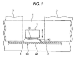
- Fig. 1 is a view showing one preferred embodiment of a wire harness installation structure of the invention, showing its construction
- Fig. 2 is a perspective view showing those portions to which a branch wire of a wire harness can be connected.
- a main wire W1 of the wire harness WH is fixed to a vehicle body panel 1, and is installed along a predetermined path.
- the branch wire W2 branches off from a predetermined portion of the wire harness WH, and this branch wire W2 is extended along the following path, and is connected at its distal end S to an electric connection box (mounting part) 2 mounted in a predetermined receiving position within a vehicle body.
- the branch wire W2 branching off from the predetermined portion of the main wire W1 of the wire harness WH, is installed along a bottom surface (lower surface) 2a of the electric connection box 2 in such a manner that the distal end S of the branch wire W2 is led from the branching position P to a left corner portion (Fig. 1) of the electric connection box 2 at the bottom surface 2a thereof.
- This left corner portion is spaced a distance, larger than the shortest distance between the branching position P and the electric connection box 2, from the branching position P.
- the distal end S of the branch wire W2 is connected to the left corner portion (the farthest position) of the bottom surface 2a of the electric connection box 2.
- the branch wire W2 has such a length that it extends from the branching position P of the main wire W1 of the wire harness WH to the left corner portion (the farthest position) of the bottom surface 2a of the electric connection box 2, and the operation for connecting the distal end S of the branch wire W2 to the electric connection box 2 and other operations can be carried out at a position into which the electric connection box 2 is drawn from the receiving position. And besides, during the operation for mounting the electric connection box 2 connected to the branch wire W2, the electric connection box 2 can be somewhat moved upward and downward (as indicated by arrows in Fig. 1) because of the sufficiently-long branch wire w2. Therefore the operations for mounting and removing the electric connection box 2 and other operations can be carried out easily.
- the connecting operation and other operations can be effected at the position into which the electric connection box 2 is drawn from the receiving position. Therefore, even in the case where other mounting parts 3 are disposed in the vicinities of the receiving position, the operation for connecting the distal end S of the branch wire W2 to the electric connection box 2 and other operations can be easily carried out.
- the length of the branch wire w2 is smaller than the predetermined length because of a design error or the like, this error or the like can be absorbed, and also even in the case where the main wire W1 and the branch wire W2 of the wire harness WH are both thick, the above operations can be carried out easily.
- the branch wire W2 of the wire harness WH is installed along the bottom surface 2a of the electric connection box 2, and by doing so, the distal end S of the branch wire W2 is led from the branching position P to the farthest portion (farthest position) of the bottom surface 2a of the electric connection box 2, and is connected thereto. Therefore, a space for receiving the branch wire W2 is hardly necessary, and the electric connection box 2 can be received in a receiving space which is generally equal to that used in the conventional structure.
- the branch wire W2 is also drawn, following the electric connection box 2.
- the electric connection box 2 it is not necessary to take the existence of the branch wire W2 into consideration, and the electric connection box 2 can be easily and smoothly drawn.
- the distal end S can be connected to those portions of the electric connection box 2 indicated by hatching in Fig. 2 except the portion of the electric connection box 2 disposed the nearest to the branching position P, and more specifically the distal end S can be connected to a rear surface 2b of the electric connection box 2 and a triangular portion of each of opposite side surfaces 2c thereof lying from a diagonal line thereof to the rear surface 2a and the bottom surface 2a.
- a front surface (one surface) 2d of the electric connection box 2 which extends just upwardly from the nearest position (which is the nearest to the branching position P of the branch wire W2) is excluded.
- the electric connection box is used as the mounting part
- the invention can be applied to various mounting parts such as a joint box, a fuse box, a relay box, a connector block, a connector of a molding protector, an auxiliary equipment and an electronic unit.
Landscapes
- Engineering & Computer Science (AREA)
- Mechanical Engineering (AREA)
- Connection Or Junction Boxes (AREA)
- Installation Of Indoor Wiring (AREA)
Abstract
Description
- This invention relates to a wire harness installation structure in which a branch wire of a wire harness is connected to a mounting part such as an electric connection box.
- There have been proposed various electric connection boxes or the like for mounting on a vehicle (see, for example, JP-A-8-207618). Among such electric connection boxes, there is the type which is connected to a branch wire of a wire harness, and this conventional example is shown in Fig. 3.
- As shown in Fig. 3, a
main wire 50 of the wire harness WH is fixed to avehicle body panel 51, and is installed along a predetermined path. Thebranch wire 52 branches off from the wire harness WH, and thisbranch wire 52 is connected to theelectric connection box 53. Theelectric connection box 53 is mounted in a predetermined receiving position within a vehicle body. - However, in the conventional structure of installing the wire harness WH, the
branch wire 52, branching off from the wire harness WH, was connected to that portion of theelectric connection box 53 which was disposed the nearest to a branching position P than the other portion thereof. Therefore, the length of thebranch wire 52 was short, and an operation for connecting thebranch wire 52 to theelectric connection box 53 and other operations could be carried out only at the receiving position (where theelectric connection box 53 is received) and its vicinity. - And besides, the
electric connection box 53, connected to thebranch wire 52, could hardly be moved from the receiving position during the mounting operation, and therefore the operations for mounting and removing theelectric connection box 53 and other operations were cumbersome. Particularly when the length of thebranch wire 52 was smaller than the predetermined length because of a design error or the like and when themain wire 50 and thebranch wire 52 were both thick, the above operations were very cumbersome. - Therefore, this invention has been made in order to solve the above problems, and an object of the invention is to provide a wire harness installation structure in which operations for mounting and removing a mounting part and other operations can be easily carried out.
- According to the present invention, there is provided a wire harness installation structure wherein a main wire of a wire harness is installed in such a manner that it is fixed to a vehicle body panel, and a mounting part is connected to a branch wire branching off from the main wire of the wire harness, and the mounting part is mounted in a predetermined receiving position within a vehicle body; provided in that the branch wire is connected to a portion of the mounting part which is spaced a distance, larger than the shortest distance between a branching position of the branch wire and the mounting part, from the branching position in a mounted condition of the mounting part, and is disposed on other surface of the mounting part than a surface thereof which extends just upwardly from a portion of the mounting part disposed the nearest to the branching position.
- The wire harness installation structure of the present invention is provided in that the branch wire is installed along a lower surface of the mounting part such that the branch wire is led from the branching position to a portion of the lower surface which is spaced a distance, larger than the shortest distance between the branching position and the mounting part, from the branching position.
- According to the present invention, the branch wire has such a length that it extends from the branching position of the main wire of the wire harness to the portion of the mounting part which is spaced a distance, larger than the shortest distance between the branching position and the mounting part, from the branching position. An operation for connecting the branch wire to the mounting part can be carried out at a position into which the mounting part is drawn from the receiving position. And besides, during an operation for mounting the mounting part connected to the branch wire, the mounting part can be somewhat moved freely because of the sufficiently-long branch wire. Therefore the operations for mounting and removing the mounting part and other operations can be carried out easily.
- According to the present invention, a space for receiving the branch wire is hardly necessary, and the mounting part can be received in a receiving space which is generally equal to that used in the conventional structure. And besides, when the mounting part is moved from the receiving position toward the drawing position, the branch wire is also drawn, following the mounting part. In the operation for drawing the mounting part, it is not necessary to take the existence of the branch wire into consideration.
-
- Fig. 1 is a view showing one preferred embodiment of a wire harness installation structure of the present invention, showing its construction.
- Fig. 2 is a perspective view showing those portions to which a branch wire of a wire harness can be connected.
- Fig. 3 is a view showing a conventional wire harness installation structure, showing its construction.
- One preferred embodiment of the present invention will now be described with reference to the drawings.
- Fig. 1 is a view showing one preferred embodiment of a wire harness installation structure of the invention, showing its construction, and Fig. 2 is a perspective view showing those portions to which a branch wire of a wire harness can be connected.
- As shown in Fig. 1, a main wire W1 of the wire harness WH is fixed to a
vehicle body panel 1, and is installed along a predetermined path. The branch wire W2 branches off from a predetermined portion of the wire harness WH, and this branch wire W2 is extended along the following path, and is connected at its distal end S to an electric connection box (mounting part) 2 mounted in a predetermined receiving position within a vehicle body. - Namely, the branch wire W2, branching off from the predetermined portion of the main wire W1 of the wire harness WH, is installed along a bottom surface (lower surface) 2a of the
electric connection box 2 in such a manner that the distal end S of the branch wire W2 is led from the branching position P to a left corner portion (Fig. 1) of theelectric connection box 2 at thebottom surface 2a thereof. This left corner portion is spaced a distance, larger than the shortest distance between the branching position P and theelectric connection box 2, from the branching position P. In a mounting operation, the distal end S of the branch wire W2 is connected to the left corner portion (the farthest position) of thebottom surface 2a of theelectric connection box 2. - In the above construction, the branch wire W2 has such a length that it extends from the branching position P of the main wire W1 of the wire harness WH to the left corner portion (the farthest position) of the
bottom surface 2a of theelectric connection box 2, and the operation for connecting the distal end S of the branch wire W2 to theelectric connection box 2 and other operations can be carried out at a position into which theelectric connection box 2 is drawn from the receiving position. And besides, during the operation for mounting theelectric connection box 2 connected to the branch wire W2, theelectric connection box 2 can be somewhat moved upward and downward (as indicated by arrows in Fig. 1) because of the sufficiently-long branch wire w2. Therefore the operations for mounting and removing theelectric connection box 2 and other operations can be carried out easily. - Furthermore, the connecting operation and other operations can be effected at the position into which the
electric connection box 2 is drawn from the receiving position. Therefore, even in the case whereother mounting parts 3 are disposed in the vicinities of the receiving position, the operation for connecting the distal end S of the branch wire W2 to theelectric connection box 2 and other operations can be easily carried out. - Furthermore, when the length of the branch wire w2 is smaller than the predetermined length because of a design error or the like, this error or the like can be absorbed, and also even in the case where the main wire W1 and the branch wire W2 of the wire harness WH are both thick, the above operations can be carried out easily.
- As described above, the branch wire W2 of the wire harness WH is installed along the
bottom surface 2a of theelectric connection box 2, and by doing so, the distal end S of the branch wire W2 is led from the branching position P to the farthest portion (farthest position) of thebottom surface 2a of theelectric connection box 2, and is connected thereto. Therefore, a space for receiving the branch wire W2 is hardly necessary, and theelectric connection box 2 can be received in a receiving space which is generally equal to that used in the conventional structure. - When the
electric connection box 2 is moved from the receiving position toward the drawing position, the branch wire W2 is also drawn, following theelectric connection box 2. In the operation for drawing theelectric connection box 2, it is not necessary to take the existence of the branch wire W2 into consideration, and theelectric connection box 2 can be easily and smoothly drawn. - In the above embodiment, although the distal end 5 of the branch wire W2 is connected to the
bottom surface 2a of theelectric connection box 2, the distal end S can be connected to those portions of theelectric connection box 2 indicated by hatching in Fig. 2 except the portion of theelectric connection box 2 disposed the nearest to the branching position P, and more specifically the distal end S can be connected to arear surface 2b of theelectric connection box 2 and a triangular portion of each ofopposite side surfaces 2c thereof lying from a diagonal line thereof to therear surface 2a and thebottom surface 2a. Namely, a front surface (one surface) 2d of theelectric connection box 2 which extends just upwardly from the nearest position (which is the nearest to the branching position P of the branch wire W2) is excluded. - In the above embodiment, although the electric connection box is used as the mounting part, the invention can be applied to various mounting parts such as a joint box, a fuse box, a relay box, a connector block, a connector of a molding protector, an auxiliary equipment and an electronic unit.
Claims (2)
- A wire harness installation structure comprising:a main wire of a wire harness is installed in such a manner that the main wire is fixed to a vehicle body panel;a branch wire branching off from the main wire of the wire harness; anda mounting part connected to the branch wire is mounted in a predetermined receiving position within a vehicle body,wherein the branch wire is connected to a portion of the mounting part with a distance longer than the shortest distance defined between a branching position of the branch wire and the portion of the mounting part in a mounted condition of the mounting part, and is disposed on other surface of the mounting part than a surface thereof which extends upwardly from a portion of the mounting part disposed the nearest to the branching position.
- A wire harness installation structure according to claim 1, the branch wire is installed along a lower surface of the mounting part such that the branch wire is led from the branching position to a portion of the lower surface with a distance larger than the shortest distance between the branching position and the mounting part.
Applications Claiming Priority (1)
| Application Number | Priority Date | Filing Date | Title |
|---|---|---|---|
| JP2004348426A JP2006158151A (en) | 2004-12-01 | 2004-12-01 | Wiring harness wiring structure |
Publications (2)
| Publication Number | Publication Date |
|---|---|
| EP1666310A1 true EP1666310A1 (en) | 2006-06-07 |
| EP1666310B1 EP1666310B1 (en) | 2013-06-26 |
Family
ID=35788140
Family Applications (1)
| Application Number | Title | Priority Date | Filing Date |
|---|---|---|---|
| EP05026150.2A Ceased EP1666310B1 (en) | 2004-12-01 | 2005-11-30 | Wire harness installation structure |
Country Status (3)
| Country | Link |
|---|---|
| US (1) | US7179997B2 (en) |
| EP (1) | EP1666310B1 (en) |
| JP (1) | JP2006158151A (en) |
Families Citing this family (5)
| Publication number | Priority date | Publication date | Assignee | Title |
|---|---|---|---|---|
| JP2007116782A (en) * | 2005-10-18 | 2007-05-10 | Yazaki Corp | Routing device |
| JP2012111406A (en) * | 2010-11-26 | 2012-06-14 | Sumitomo Wiring Syst Ltd | Wire harness cable routing structure, and protector |
| JP6644824B2 (en) * | 2018-04-04 | 2020-02-12 | 矢崎総業株式会社 | Branch circuit body and branching method of electric wire |
| JP6691164B2 (en) * | 2018-04-04 | 2020-04-28 | 矢崎総業株式会社 | Branching circuit body and wire branching method |
| JP7153037B2 (en) * | 2020-01-17 | 2022-10-13 | 矢崎総業株式会社 | wire harness |
Citations (3)
| Publication number | Priority date | Publication date | Assignee | Title |
|---|---|---|---|---|
| US5954538A (en) * | 1997-07-28 | 1999-09-21 | Grand General Accessories Manufacturing Inc. | Set of harnesses for interconnecting a plurality of ornamental light fixtures in a vehicle |
| EP1110796A1 (en) * | 1998-07-21 | 2001-06-27 | Harness System Technologies Research, Ltd. | Wiring structure for instrument panel of vehicle |
| US6259027B1 (en) * | 1998-03-16 | 2001-07-10 | Yazaki Corporation | Compact wire harness for connecting electrical equipment |
Family Cites Families (16)
| Publication number | Priority date | Publication date | Assignee | Title |
|---|---|---|---|---|
| US1837962A (en) * | 1928-07-03 | 1931-12-22 | Gen Electric | Manufacture of electrical apparatus |
| US2299140A (en) * | 1939-06-28 | 1942-10-20 | Union Carbide & Carbon Corp | Wire harness |
| US3128214A (en) * | 1959-04-06 | 1964-04-07 | Ling Temco Vought Inc | Method of making multiconductor cable |
| US3055971A (en) * | 1959-09-25 | 1962-09-25 | Gen Motors Corp | Panel wiring assemblies |
| US3984622A (en) * | 1976-02-20 | 1976-10-05 | Southern Weaving Company | Multi-conductor cable harness with woven breakout cover and method of making same |
| US4280062A (en) * | 1979-08-22 | 1981-07-21 | Douglas Dynamics Inc. | Auxiliary light wiring harness |
| JP2913951B2 (en) * | 1991-09-26 | 1999-06-28 | 住友電装株式会社 | Routing method of wire harness for door |
| JPH0546607U (en) * | 1991-12-04 | 1993-06-22 | 富士重工業株式会社 | Wire harness intermediate output device |
| JP3312537B2 (en) | 1994-09-14 | 2002-08-12 | 住友電装株式会社 | Automotive branch connection device |
| JP3169041B2 (en) | 1994-10-06 | 2001-05-21 | 矢崎総業株式会社 | Electric wire holding method and structure using electric junction box |
| JP3009024B2 (en) | 1995-04-14 | 2000-02-14 | 矢崎総業株式会社 | Branch wire harness support structure |
| JP3022256B2 (en) | 1995-06-13 | 2000-03-15 | 住友電装株式会社 | Temporary holding mechanism for electrical junction box |
| JP3031204B2 (en) | 1995-06-28 | 2000-04-10 | 住友電装株式会社 | Temporary holding mechanism for electrical junction box and method for mounting electrical junction box |
| US5994645A (en) * | 1996-06-14 | 1999-11-30 | Sumitomo Wiring Systems, Ltd. | Wiring harness arranging construction |
| US6291770B1 (en) * | 1999-05-14 | 2001-09-18 | Leoni Wiring Systems, Inc. | Wiring system and method therefor |
| US6621688B1 (en) * | 2002-06-26 | 2003-09-16 | Alcoa Fujikura Limited | Electrical distribution system having integral junction box for instrument panel application |
-
2004
- 2004-12-01 JP JP2004348426A patent/JP2006158151A/en active Pending
-
2005
- 2005-11-30 EP EP05026150.2A patent/EP1666310B1/en not_active Ceased
- 2005-12-01 US US11/290,421 patent/US7179997B2/en not_active Expired - Lifetime
Patent Citations (3)
| Publication number | Priority date | Publication date | Assignee | Title |
|---|---|---|---|---|
| US5954538A (en) * | 1997-07-28 | 1999-09-21 | Grand General Accessories Manufacturing Inc. | Set of harnesses for interconnecting a plurality of ornamental light fixtures in a vehicle |
| US6259027B1 (en) * | 1998-03-16 | 2001-07-10 | Yazaki Corporation | Compact wire harness for connecting electrical equipment |
| EP1110796A1 (en) * | 1998-07-21 | 2001-06-27 | Harness System Technologies Research, Ltd. | Wiring structure for instrument panel of vehicle |
Also Published As
| Publication number | Publication date |
|---|---|
| EP1666310B1 (en) | 2013-06-26 |
| US20060141810A1 (en) | 2006-06-29 |
| US7179997B2 (en) | 2007-02-20 |
| JP2006158151A (en) | 2006-06-15 |
Similar Documents
| Publication | Publication Date | Title |
|---|---|---|
| US7825339B2 (en) | Protector | |
| US9485892B2 (en) | Flat wiring body module | |
| JP3923281B2 (en) | Mounting structure for vehicle equipment | |
| US20100326690A1 (en) | Electrical junction box | |
| CN105050863B (en) | Wiring unit for automatic transmission and holding plate used in the wiring unit | |
| JP5052960B2 (en) | Wire harness system | |
| EP1547872B1 (en) | Structure of mounting of device for vehicle | |
| US6702356B2 (en) | Instrument panel module including power/signal transmission system for vehicle | |
| US6724613B2 (en) | Door-use feed protector and a circuit assembly arranging structure using the same | |
| EP1666310B1 (en) | Wire harness installation structure | |
| JP2003048495A (en) | Power supply for sliding door | |
| JP6018876B2 (en) | Protector | |
| KR20190007384A (en) | Connector back shell assembly | |
| CN105050862B (en) | Wiring unit for automatic transmission | |
| CN112046261A (en) | Vehicle and drive unit | |
| US6172302B1 (en) | Harness cover for electrical connection box and assembly having the same | |
| WO2016039446A1 (en) | Electrical connection box | |
| JP2005056630A (en) | Connector housing and wire harness provided therewith | |
| KR102123953B1 (en) | Vehecle block with wiring structure and manufacturing method there of | |
| JP6103387B2 (en) | Protective case | |
| JP7577997B2 (en) | vehicle | |
| JP4252992B2 (en) | Electrical junction box | |
| JP7549816B2 (en) | Harness protection structure | |
| JP2025180347A (en) | Drip-proof construction of electronic devices | |
| JP2014100971A (en) | Wiring harness system |
Legal Events
| Date | Code | Title | Description |
|---|---|---|---|
| PUAI | Public reference made under article 153(3) epc to a published international application that has entered the european phase |
Free format text: ORIGINAL CODE: 0009012 |
|
| AK | Designated contracting states |
Kind code of ref document: A1 Designated state(s): AT BE BG CH CY CZ DE DK EE ES FI FR GB GR HU IE IS IT LI LT LU LV MC NL PL PT RO SE SI SK TR |
|
| AX | Request for extension of the european patent |
Extension state: AL BA HR MK YU |
|
| 17P | Request for examination filed |
Effective date: 20060719 |
|
| 17Q | First examination report despatched |
Effective date: 20060904 |
|
| AKX | Designation fees paid |
Designated state(s): DE FR GB |
|
| RAP1 | Party data changed (applicant data changed or rights of an application transferred) |
Owner name: YAZAKI CORPORATION |
|
| GRAP | Despatch of communication of intention to grant a patent |
Free format text: ORIGINAL CODE: EPIDOSNIGR1 |
|
| GRAS | Grant fee paid |
Free format text: ORIGINAL CODE: EPIDOSNIGR3 |
|
| GRAA | (expected) grant |
Free format text: ORIGINAL CODE: 0009210 |
|
| AK | Designated contracting states |
Kind code of ref document: B1 Designated state(s): DE FR GB |
|
| REG | Reference to a national code |
Ref country code: GB Ref legal event code: FG4D |
|
| REG | Reference to a national code |
Ref country code: DE Ref legal event code: R096 Ref document number: 602005040122 Country of ref document: DE Effective date: 20130822 |
|
| PLBE | No opposition filed within time limit |
Free format text: ORIGINAL CODE: 0009261 |
|
| STAA | Information on the status of an ep patent application or granted ep patent |
Free format text: STATUS: NO OPPOSITION FILED WITHIN TIME LIMIT |
|
| 26N | No opposition filed |
Effective date: 20140327 |
|
| REG | Reference to a national code |
Ref country code: DE Ref legal event code: R097 Ref document number: 602005040122 Country of ref document: DE Effective date: 20140327 |
|
| REG | Reference to a national code |
Ref country code: FR Ref legal event code: PLFP Year of fee payment: 11 |
|
| REG | Reference to a national code |
Ref country code: FR Ref legal event code: PLFP Year of fee payment: 12 |
|
| REG | Reference to a national code |
Ref country code: FR Ref legal event code: PLFP Year of fee payment: 13 |
|
| REG | Reference to a national code |
Ref country code: FR Ref legal event code: PLFP Year of fee payment: 14 |
|
| PGFP | Annual fee paid to national office [announced via postgrant information from national office to epo] |
Ref country code: FR Payment date: 20221010 Year of fee payment: 18 |
|
| PGFP | Annual fee paid to national office [announced via postgrant information from national office to epo] |
Ref country code: GB Payment date: 20221006 Year of fee payment: 18 Ref country code: DE Payment date: 20221004 Year of fee payment: 18 |
|
| REG | Reference to a national code |
Ref country code: DE Ref legal event code: R119 Ref document number: 602005040122 Country of ref document: DE |
|
| GBPC | Gb: european patent ceased through non-payment of renewal fee |
Effective date: 20231130 |
|
| PG25 | Lapsed in a contracting state [announced via postgrant information from national office to epo] |
Ref country code: DE Free format text: LAPSE BECAUSE OF NON-PAYMENT OF DUE FEES Effective date: 20240601 |
|
| PG25 | Lapsed in a contracting state [announced via postgrant information from national office to epo] |
Ref country code: GB Free format text: LAPSE BECAUSE OF NON-PAYMENT OF DUE FEES Effective date: 20231130 |
|
| PG25 | Lapsed in a contracting state [announced via postgrant information from national office to epo] |
Ref country code: FR Free format text: LAPSE BECAUSE OF NON-PAYMENT OF DUE FEES Effective date: 20231130 |
|
| PG25 | Lapsed in a contracting state [announced via postgrant information from national office to epo] |
Ref country code: GB Free format text: LAPSE BECAUSE OF NON-PAYMENT OF DUE FEES Effective date: 20231130 Ref country code: FR Free format text: LAPSE BECAUSE OF NON-PAYMENT OF DUE FEES Effective date: 20231130 Ref country code: DE Free format text: LAPSE BECAUSE OF NON-PAYMENT OF DUE FEES Effective date: 20240601 |