EP1664891B1 - Method of manufacturing acylindrical optical devices - Google Patents
Method of manufacturing acylindrical optical devices Download PDFInfo
- Publication number
- EP1664891B1 EP1664891B1 EP04782621A EP04782621A EP1664891B1 EP 1664891 B1 EP1664891 B1 EP 1664891B1 EP 04782621 A EP04782621 A EP 04782621A EP 04782621 A EP04782621 A EP 04782621A EP 1664891 B1 EP1664891 B1 EP 1664891B1
- Authority
- EP
- European Patent Office
- Prior art keywords
- lens system
- lens
- optical
- recited
- final
- Prior art date
- Legal status (The legal status is an assumption and is not a legal conclusion. Google has not performed a legal analysis and makes no representation as to the accuracy of the status listed.)
- Expired - Lifetime
Links
Images




Classifications
-
- G—PHYSICS
- G02—OPTICS
- G02B—OPTICAL ELEMENTS, SYSTEMS OR APPARATUS
- G02B7/00—Mountings, adjusting means, or light-tight connections, for optical elements
- G02B7/02—Mountings, adjusting means, or light-tight connections, for optical elements for lenses
-
- G—PHYSICS
- G02—OPTICS
- G02B—OPTICAL ELEMENTS, SYSTEMS OR APPARATUS
- G02B23/00—Telescopes, e.g. binoculars; Periscopes; Instruments for viewing the inside of hollow bodies; Viewfinders; Optical aiming or sighting devices
- G02B23/24—Instruments or systems for viewing the inside of hollow bodies, e.g. fibrescopes
- G02B23/2407—Optical details
- G02B23/2446—Optical details of the image relay
-
- G—PHYSICS
- G02—OPTICS
- G02B—OPTICAL ELEMENTS, SYSTEMS OR APPARATUS
- G02B23/00—Telescopes, e.g. binoculars; Periscopes; Instruments for viewing the inside of hollow bodies; Viewfinders; Optical aiming or sighting devices
- G02B23/24—Instruments or systems for viewing the inside of hollow bodies, e.g. fibrescopes
- G02B23/2476—Non-optical details, e.g. housings, mountings, supports
Definitions
- This invention generally relates to optical devices and methods for the manufacture of such optical devices and more particularly to optical devices with lens systems of a small diameter.
- Endoscopes are examples of optical devices that utilize optical systems characterized by an assembly of a plurality of optical elements, such as lenses, that are serially disposed along an optical axis.
- a lens system comprising multiple lens elements at a distal end constitutes an objective; a lens system at the proximal end constitutes an eyepiece; and one or more groups of intermediate lens elements define one or more relay lens systems.
- Endoscopes utilizing such systems generally have working channels and lumens. Some working channels are filled with fiber to enable an external light source to illuminate a field of view. Others allow a surgeon to move instruments along the length of the endoscope to perform some function at the distal end while simultaneously viewing the area being treated. Still other working channels allow a surgeon to dispense a therapeutic, diagnostic or other material at the distal end of the endoscope, again while simultaneously viewing the area being treated.
- Endoscopes and other optical devices of this nature generally are formed with cylindrical lens elements extending along a centered optical axis.
- the lens elements generally have concave, planar or convex end, image forming surfaces that are transverse to the optical axis.
- Multiple lens elements may be adjoined in lens systems in order to achieve particular optical characteristics, all as known in the prior art.
- Such lens elements and lens systems are called centered, rotationally symmetrical lens elements and systems, respectively.
- optical devices that have smaller and smaller diameters.
- some optical devices are now produced with an outer diameter of 1 to 2 mm using traditional lens making methods.
- products that achieve these goals are difficult to manufacture with traditional lens making methods.
- Traditional lens making methods include grinding and polishing operations to produce approximately spherical or other shaped image forming surfaces at the entrance and exit faces that define the optical characteristics of that lens element. Then the lens element is rotated about its geometric axis that will generally lie on the optical axis. A geometric axis is defined as a straight line locus of the centers of curvature of the refracting surfaces.
- the outer lens boundary then can be made essentially circular, as by abrasive grinding, such that the result is essentially a right circular cylinder with or imaging forming spherical end surfaces and a cylindrically centered axis, i.e., a centered, rotationally symmetrical lens element. Individual lens elements can then be adjoined along the optical or geometric axis to form a lens system.
- the final diameter of the lens is controlled by the location of the grinding or edging tool with respect to the optical axis including any positional variation due to tolerances in the manufacturing equipment. In conventional lenses these tolerances do not constitute a significant portion of the overall lens diameter.
- to achieve an absolute tolerance as a constant percentage of very small diameters requires extreme accuracy and tools that operate with extremely close tolerances. Machines for providing such accuracies become increasingly expensive as tolerance requirements become more stringent.
- a lens element generally has an axial length that is several times the diameter. At small diameters it becomes difficult to support the lens element so that its optical axis remains in a single position relative to a tool reference. Moreover, as the diameter decreases the lens element becomes, in effect, more brittle and thus extremely fragile. These factors lead to an increased potential for breakage during manufacture.
- lens systems in most currently commercially available endoscopes have an outer diameter of approximately 1.7 mm or greater. Endoscopes with such readily available lens elements are too big to be used in many applications including medical applications such as viewing fine vascular structure, minimally invasive endoscopy such as neurological and neurosurgical applications and arthoscopy, ear, nose and throat (ENT) applications, cardiac surgical applications, and many endoscope applications that can benefit from the use of stereoscopic endoscopes.
- medical applications such as viewing fine vascular structure, minimally invasive endoscopy such as neurological and neurosurgical applications and arthoscopy, ear, nose and throat (ENT) applications, cardiac surgical applications, and many endoscope applications that can benefit from the use of stereoscopic endoscopes.
- the present invention is directed to a method for making a lens system, generally of the type disclosed in EP-1,211,525 and defined in the preamble of claim 1.
- What is needed is a method for enabling the manufacture of lens elements and lens systems, having maximum cross sectional dimensions that can be as little as 1 mm or less.
- Another object of this invention is to provide a method capable of manufacturing a lens element with high centering accuracy that is capable of being made with a diameter of less than approximately 1 mm.
- Still another object of this invention is to provide a method capable of manufacturing lens systems from a conventional centered, rotationally symmetrical lens system useful in optical devices with an outer diameter reduced to less than 1 mm wherein the final lens system exhibits point symmetry.
- FIGS. 1 through 3 depict a portion of an optical device 20, such as an endoscope, constructed in accordance with this invention that lies along an axis 21.
- the optical device 20 includes a lens system 22 with adjoined lens elements 23, 24 and 25.
- Each of the lens elements 23, 24 and 25 and the lens system 22 have centered rotational symmetry with respect to the axis 21.
- the axis 21 is coincident with the optical and geometric axes of the optical device.
- the end surfaces of each lens element constitute image forming surfaces that are polished, generally spherical surfaces that produce an image of any object proximate the axis 21.
- FIGS. 1 through 3 do not depict a specific spherical surface.
- a flat traverse surface is shown as a representation of an entire class of image forming surfaces.
- a sheath 26 circumscribes the lens system 22 and defines an outer diameter do.
- the lens element 23, like the lens elements 24 and 25, has a polygonal shape in cross-section, in this particular embodiment a regular polygon cross-section and specifically a square cross-section. That is, in cross section the lens element 23, and all the other lens elements in the lens system 22, form a square bounded by four flat surfaces 30, 31, 32 and 33 that intersect at right angles and are equidistant from the axis 21.
- the axis 21 is representative of the optical axis and the geometric axis because these axes are coincident.
- each face forms a chord that, with the sheath 25 defines an axially extending working channel with a cross section in the form of a segment.
- Such working channels are called “segmental working channels” in the following description.
- segmental working channel faces 30 through 33 define one boundary of each of segmental working channels 34, 35, 36 and 37, respectively.
- At least one of these segmental working channels, such as the segmental working channel 36 could be used to contain optical fibers 30 for transferring light from the proximal end of the optical device beyond the distal end to illuminate a field of view.
- the other segmental working channels could accommodate instruments or therapeutic or diagnostic material or both or other agents such as water and saline solution.
- one characteristic of this invention is that placing a lens system with a polygonal cross section in a circumscribing cylindrical sheath automatically produces the segmental working channels. It will also be apparent that the transverse cross sectional area of a segmental working channel increases as the number of faces decreases.
- Optical devices such as shown in FIGS. 1 through 3 can have a wide range of diameters.
- Lens assemblies in accordance with this invention have been constructed with outer sheath diameters, d o , of 1.2 mm. Optical devices with even smaller diameters are anticipated.
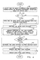
- Step 60 in FIG. 4 represents the selection of one or more initial cylindrical lens elements characterized by having a centered rotational symmetry with coincident optical and geometric axes. If it is an objective to produce a three-piece initial lens assembly, process 60 represents the selection of optical elements 61, 62 and 63 as shown in FIG. 5A with the cross section shown in FIG. 6A .
- the diameter should be at least as large as the diameter of a circle that will circumscribe the final lens system.
- Step 65 in FIG. 4 sets up the formation of one or more initial lens assemblies.
- FIG. 5B shows a single initial lens assembly 66 formed by joining, typically by cementing, the initial lens elements 61 through 63 along an optical axis 67.
- a cross-section FIG. 6B depicts the initial lens system 66 with its circular cross section and one initial lens element 62 that is centered on the optical axis 67.
- the lens elements 61 through 63 and the lens assembly 66 are characterized by a centered rotational symmetry about the optical axis 67. Moreover, the optical axis 67 is coincident with the geometrical axes through the initial lens assembly 66 and each of the initial lens elements 61 through 63.
- step 70 of FIG. 4 represents the procedure of providing a support for each initial lens assembly, such as the initial lens assembly 66.
- a tool 71 in FIG. 5C is formed with a plurality of parallel support slots 72. The slot width is selected to provide a stable support for an initial lens system.
- FIG. 5C shows the single initial lens system 66 for clarity. It also will become apparent that multiple initial lens systems may be positioned in each support slot. It will be apparent that these multiple initial lens systems can be spaced along a single slot and have different initial lens elements. Generally it is merely necessary to assure that all the lens systems in a single support slot should be selected so they will have the same finished cross section.
- the tool 71 is formed of a float glass plate and the support slots 72 are formed by a dicing saw. Dicing saws are regularly used in the semiconductor industry and are constructed to have cutting tolerances consistent with an indexing accuracy cumulative error of 0.001 mm per 160 mm traversal or less.
- thermoplastic cement 73 fills the support slots, like the support slot 72 to capture each initial lens assembly, such as the initial lens system 66, in the tool 71.
- Step 74 in FIG. 4 represents a process by which a portion of the initial lens system 66 is removed to form a sawn planar face 75 of FIG. 6D that is equally spaced from the desired final geometric axis that in this specific example is coincident with the optical axis 67.
- the distance to the final geometric axis measured perpendicular to a face, such as the sawn face 75 of FIG. 6D is (d i /2)sin 45° where d i represents the desired finished size of the lens system measured diagonally between opposite corners. As will be apparent, this distance is one-half of the width of a face.
- a dicing saw 76 positioned to form a vertical cut relative to the tool 71, removes material from the lens assembly to define the sawn face 75 at some predetermined distance from the axis 67.
- Commercially available dicing saws make such a cut so that the face 75 is at a fixed distance from the optical axis 67 with an accuracy of 0.001 mm per 160 mm of traversal or less.
- Step 77 of FIG. 4 transfers control to step 80 that represents a procedure for properly supporting the lens systems for forming another sawn face.
- step 80 requires that the tool 71 be rotated 180° and realigned.
- the dicing saw 76 is positioned so that it saws a face 81 that is parallel to the face 75 and is equidistant from the geometric axis.
- step 80 in FIG. 4 needs to rotate the lens systems by 90°, such as by removing them from the tool 71 and placing them in another tool 82 having wider support sloths 83 as shown in FIGS. 5F and 6F .
- a thermosetting material 84 then fills the support slots 83 to capture the lens system 66.
- the facers 75 and 81 are horizontal and in FIGS. 5F and 6F the face 75 is above the face 81.
- the lens system 66 obviously could be reversed such that the face 75 was in contact with the tool 82.
- Steps 77 and 80 in FIG. 4 represent the procedures by which the lens systems are sawn in succession.
- the dicing saw produces a third sawn face 88 that is perpendicular to the sawn faces 75 and 81 and that is equidistant from the geometric axis 67.
- the tool 82 can be rotated 180° and aligned as shown in FIGS. 5H and 6H , so the dicing saw produces a fourth sawn face 90 parallel to the third sawn face 88, perpendicular to the sawn faces 75 and 81 and equidistant from the geometric axis 67.
- step 91 in FIG. 4 represents the step of removing each final lens system from the tool 82.
- Step 92 represents the procedure of supporting the final lens systems in a sheath 93 as shown in FIGS. 5I and 6I to complete the optical device.
- FIG. 4 merely provide a work path organization to depict the various major processes to produce lens elements and systems in accordance with this invention. It will also be apparent that this method of manufacture by successive sawing of an initial lens system produces a final lens system that has a very small diameter without the need for expensive grinding or other operations.
- This procedure allows a manufacturer to use large conventional, economical lens elements as a foundation for the very small lens assembles. With each sawing operation the lens assembly becomes smaller. However, sawing allows the lens assembly to be fully supported during all the operations. This compensates for any breakage due to an increasing brittle nature of the lens assembly as manufacture proceeds.
- steps 60, 65, 70, 74, 80, 91 and 92 and decisions 64 and 77 all operate to produce a lens system having a plurality of axially extending flat sawn faces that lie in intersecting planes.
- This process has been used successfully to manufacture centered, point symmetric lenses circumscribed by a sheath having an inner diameter of 0.6mm and an outer diameter of 0.85 mm.
- Optical devices with such reduced diameter or even smaller diameters will be useful in a large number of applications heretofore unavailable for endoscopic diagnosis and therapy.
- FIG. 7A schematically depicts such a configuration in which optical axis 67 is coincident with the geometric axis of the initial lens assembly 66 and the final lens assembly 22.
- FIG. 7B depicts a variation in which the optical and geometric axis 67 of the lens assembly 66 are parallel but spaced. Processing according to FIG.
- the support of the lens systems positions them to produce sawn planar faces at predetermined positions from a geometric axis 95B that is offset from the optical axis 67.
- the boundary of the resulting final lens system 22B includes the optical axis 67.
- FIG. 7C depicts a final lens system 22C with a geometric axis 95C offset from the optical axis 67.
- the optical axis 67 lies outside the boundaries of the final lens system 22C.
- Such an approach would be useful for producing lens systems with unobstructive apertures "eccentric pupil” systems) such as a confocal reflective microscope or a Schwarzchild arrangement microscopic or telescopic system.
- Each of the foregoing embodiments is characterized by a geometric axis that is coincident with or parallel to the optical axis of an initial lens assembly.
- the sawing operation might also be controlled to produce sawn faces parallel to a geometric axis that is oblique to the optical axis.
- This invention has been described in terms of initial and final lens assemblies. Multiple lens assemblies can also be produced each having different structures. Those different lens assemblies could form lens subassemblies such as objectives, eyepieces and relay lens assemblies for use in endoscopes with each optical device being held in a single sheath or individual sheath assemblies being positioned in an outer sheath. It will also become apparent that other sawing techniques may be used or may come into existence that will provide even better tolerances than are currently available to enable the construction of even smaller lenses and numerous lens geometries and sizes. Also each optical device is described with a cylindrical sheath. It will also be apparent that the sheath can have other cross sectional shapes, such as a polygonal shape and that the sheath may or may not define one or more working channels.
Landscapes
- Physics & Mathematics (AREA)
- General Physics & Mathematics (AREA)
- Optics & Photonics (AREA)
- Astronomy & Astrophysics (AREA)
- Endoscopes (AREA)
- Eyeglasses (AREA)
- Instruments For Viewing The Inside Of Hollow Bodies (AREA)
- Glass Compositions (AREA)
Abstract
Description
- This invention generally relates to optical devices and methods for the manufacture of such optical devices and more particularly to optical devices with lens systems of a small diameter.
- Endoscopes are examples of optical devices that utilize optical systems characterized by an assembly of a plurality of optical elements, such as lenses, that are serially disposed along an optical axis. In an endoscope, for example, a lens system comprising multiple lens elements at a distal end constitutes an objective; a lens system at the proximal end constitutes an eyepiece; and one or more groups of intermediate lens elements define one or more relay lens systems.
- Endoscopes utilizing such systems generally have working channels and lumens. Some working channels are filled with fiber to enable an external light source to illuminate a field of view. Others allow a surgeon to move instruments along the length of the endoscope to perform some function at the distal end while simultaneously viewing the area being treated. Still other working channels allow a surgeon to dispense a therapeutic, diagnostic or other material at the distal end of the endoscope, again while simultaneously viewing the area being treated.
- Endoscopes and other optical devices of this nature generally are formed with cylindrical lens elements extending along a centered optical axis. The lens elements generally have concave, planar or convex end, image forming surfaces that are transverse to the optical axis. Multiple lens elements may be adjoined in lens systems in order to achieve particular optical characteristics, all as known in the prior art. Such lens elements and lens systems are called centered, rotationally symmetrical lens elements and systems, respectively.
- Medical personnel who use these optical devices now indicate a preference for optical devices that have smaller and smaller diameters. In fact some optical devices are now produced with an outer diameter of 1 to 2 mm using traditional lens making methods. However products that achieve these goals are difficult to manufacture with traditional lens making methods.
- Traditional lens making methods include grinding and polishing operations to produce approximately spherical or other shaped image forming surfaces at the entrance and exit faces that define the optical characteristics of that lens element. Then the lens element is rotated about its geometric axis that will generally lie on the optical axis. A geometric axis is defined as a straight line locus of the centers of curvature of the refracting surfaces. The outer lens boundary then can be made essentially circular, as by abrasive grinding, such that the result is essentially a right circular cylinder with or imaging forming spherical end surfaces and a cylindrically centered axis, i.e., a centered, rotationally symmetrical lens element. Individual lens elements can then be adjoined along the optical or geometric axis to form a lens system.
- The ability to make smaller optical devices including those with lens systems that continue to exhibit centered rotationally symmetrical characteristics, becomes more difficult as the lens diameter reduces. First, the final diameter of the lens is controlled by the location of the grinding or edging tool with respect to the optical axis including any positional variation due to tolerances in the manufacturing equipment. In conventional lenses these tolerances do not constitute a significant portion of the overall lens diameter. However, to achieve an absolute tolerance as a constant percentage of very small diameters requires extreme accuracy and tools that operate with extremely close tolerances. Machines for providing such accuracies become increasingly expensive as tolerance requirements become more stringent.
- Second, in these optical devices, a lens element generally has an axial length that is several times the diameter. At small diameters it becomes difficult to support the lens element so that its optical axis remains in a single position relative to a tool reference. Moreover, as the diameter decreases the lens element becomes, in effect, more brittle and thus extremely fragile. These factors lead to an increased potential for breakage during manufacture.
- Thus about 1-2 mm tends to be a practical minimum diameter for any lens element manufactured by traditional lens manufacturing methods. Lens systems in most currently commercially available endoscopes have an outer diameter of approximately 1.7 mm or greater. Endoscopes with such readily available lens elements are too big to be used in many applications including medical applications such as viewing fine vascular structure, minimally invasive endoscopy such as neurological and neurosurgical applications and arthoscopy, ear, nose and throat (ENT) applications, cardiac surgical applications, and many endoscope applications that can benefit from the use of stereoscopic endoscopes.
- The present invention is directed to a method for making a lens system, generally of the type disclosed in
EP-1,211,525 and defined in the preamble ofclaim 1. - What is needed is a method for enabling the manufacture of lens elements and lens systems, having maximum cross sectional dimensions that can be as little as 1 mm or less.
- Therefore it is an object of this invention to provide a method capable of manufacturing lens systems that are less than 1 or 2 mm in diameter.
- Another object of this invention is to provide a method capable of manufacturing a lens element with high centering accuracy that is capable of being made with a diameter of less than approximately 1 mm.
- Still another object of this invention is to provide a method capable of manufacturing lens systems from a conventional centered, rotationally symmetrical lens system useful in optical devices with an outer diameter reduced to less than 1 mm wherein the final lens system exhibits point symmetry.
- According to the present invention there is provided a method for making a lens system as defined in the characterising clause of
claim 1. - Various embodiments of the present invention will now be described with reference to the accompanying drawings in which like reference numerals refer to like parts, and in which:
-
FIG. 1 is a perspective view of an optical device constructed in accordance with one embodiment of this invention; -
FIG. 2 is a cross-section of the optical device taken along lines 2-2 inFIG. 1 ; -
FIG. 3 is another perspective view to illustrate the construction of the optical device inFIGS. 1 and 2 ; -
FIG. 4 is a chart that depicts major steps in the manufacturing process for obtaining the optical device shown inFIG. 1 ; -
FIGS. 5A through 5I are illustrative of certain steps in the manufacturing process shown inFIG. 4 ; and -
FIGS. 6A through 6I are illustrative of the appearance of an optical device at various stages during the manufacturing process ofFIG. 4 ; and -
FIGS. 7A through 7C are useful in understanding variations of the method and construction depicted inFIGS. 1 through 6I . -
FIGS. 1 through 3 depict a portion of anoptical device 20, such as an endoscope, constructed in accordance with this invention that lies along anaxis 21. In this embodiment, theoptical device 20 includes alens system 22 withadjoined lens elements lens elements lens system 22 have centered rotational symmetry with respect to theaxis 21. In this particular embodiment, theaxis 21 is coincident with the optical and geometric axes of the optical device. Although not shown, but as will be known to persons of ordinary skill in the art, the end surfaces of each lens element constitute image forming surfaces that are polished, generally spherical surfaces that produce an image of any object proximate theaxis 21. As manufacture and use of lens elements with such surfaces are known,FIGS. 1 through 3 do not depict a specific spherical surface. A flat traverse surface is shown as a representation of an entire class of image forming surfaces. - A
sheath 26 circumscribes thelens system 22 and defines an outer diameter do. Referring specifically toFIG. 2 and in accordance with this invention, thelens element 23, like thelens elements lens element 23, and all the other lens elements in thelens system 22, form a square bounded by fourflat surfaces axis 21. Moreover, inFIGS. 1 through 3 theaxis 21 is representative of the optical axis and the geometric axis because these axes are coincident. - As the
sheath 26 is circular and circumscribes thesquare lens element 23, each face forms a chord that, with thesheath 25 defines an axially extending working channel with a cross section in the form of a segment. Such working channels are called "segmental working channels" in the following description. InFIGS. 1 through 3 segmental working channel faces 30 through 33 define one boundary of each ofsegmental working channels channel 36, could be used to containoptical fibers 30 for transferring light from the proximal end of the optical device beyond the distal end to illuminate a field of view. The other segmental working channels could accommodate instruments or therapeutic or diagnostic material or both or other agents such as water and saline solution. - As will be apparent, one characteristic of this invention is that placing a lens system with a polygonal cross section in a circumscribing cylindrical sheath automatically produces the segmental working channels. It will also be apparent that the transverse cross sectional area of a segmental working channel increases as the number of faces decreases.
- Optical devices such as shown in
FIGS. 1 through 3 can have a wide range of diameters. Lens assemblies in accordance with this invention have been constructed with outer sheath diameters, do, of 1.2 mm. Optical devices with even smaller diameters are anticipated. - The method for making these lenses is described in
FIGS. 4 ,5A through 5I and 6A through 6I . This particular method is described with respect to manufacturing a final lens system or systems in which the geometric and optical axes are coincident and in which a cross section normal to the axes is a square.Step 60 inFIG. 4 represents the selection of one or more initial cylindrical lens elements characterized by having a centered rotational symmetry with coincident optical and geometric axes. If it is an objective to produce a three-piece initial lens assembly,process 60 represents the selection ofoptical elements FIG. 5A with the cross section shown inFIG. 6A . The diameter should be at least as large as the diameter of a circle that will circumscribe the final lens system. These lens elements will have different end faces forming convex, concave, planar or other image forming surfaces in order to achieve the desired optical characteristics as previously described. - Referring to
FIG. 4 , if, as in this example, a decision is made atstep 64 ofFIG. 4 as to whether a final lens system will contain multiple lens elements like the lens system shown inFIG. 5B with the geometric axis of the final lens system (hereinafter the "final geometric axis") coincident with theoptical axis 67.Step 65 inFIG. 4 sets up the formation of one or more initial lens assemblies.FIG. 5B shows a singleinitial lens assembly 66 formed by joining, typically by cementing, theinitial lens elements 61 through 63 along anoptical axis 67. A cross-sectionFIG. 6B depicts theinitial lens system 66 with its circular cross section and oneinitial lens element 62 that is centered on theoptical axis 67. As previously indicated, thelens elements 61 through 63 and thelens assembly 66 are characterized by a centered rotational symmetry about theoptical axis 67. Moreover, theoptical axis 67 is coincident with the geometrical axes through theinitial lens assembly 66 and each of theinitial lens elements 61 through 63. - Once the initial lens assembly is formed, step 70 of
FIG. 4 represents the procedure of providing a support for each initial lens assembly, such as theinitial lens assembly 66. In accordance with one aspect of this invention, atool 71 inFIG. 5C is formed with a plurality ofparallel support slots 72. The slot width is selected to provide a stable support for an initial lens system.FIG. 5C shows the singleinitial lens system 66 for clarity. It also will become apparent that multiple initial lens systems may be positioned in each support slot. It will be apparent that these multiple initial lens systems can be spaced along a single slot and have different initial lens elements. Generally it is merely necessary to assure that all the lens systems in a single support slot should be selected so they will have the same finished cross section. - In one particular embodiment, the
tool 71 is formed of a float glass plate and thesupport slots 72 are formed by a dicing saw. Dicing saws are regularly used in the semiconductor industry and are constructed to have cutting tolerances consistent with an indexing accuracy cumulative error of 0.001 mm per 160 mm traversal or less. - As shown in
FIGS. 5C and 6C , athermoplastic cement 73 fills the support slots, like thesupport slot 72 to capture each initial lens assembly, such as theinitial lens system 66, in thetool 71. Theinitial lens system 66, particularly theinitial lens element 62, now lies in thesupport slot 72 filled with thethermoplastic cement 73 and is rigidly fixed. This process positions the initial lens systems accurately for subsequent processing. -
Step 74 inFIG. 4 represents a process by which a portion of theinitial lens system 66 is removed to form a sawnplanar face 75 ofFIG. 6D that is equally spaced from the desired final geometric axis that in this specific example is coincident with theoptical axis 67. In accordance with one aspect of this invention, the distance to the final geometric axis measured perpendicular to a face, such as the sawnface 75 ofFIG. 6D is (di/2)sin 45° where di represents the desired finished size of the lens system measured diagonally between opposite corners. As will be apparent, this distance is one-half of the width of a face. - As shown in
FIGS. 5D and 6D , a dicing saw 76, positioned to form a vertical cut relative to thetool 71, removes material from the lens assembly to define the sawnface 75 at some predetermined distance from theaxis 67. Commercially available dicing saws make such a cut so that theface 75 is at a fixed distance from theoptical axis 67 with an accuracy of 0.001 mm per 160 mm of traversal or less.Step 77 ofFIG. 4 transfers control to step 80 that represents a procedure for properly supporting the lens systems for forming another sawn face. To produce a final lens system with a square cross section in a plane normal to the finalgeometric axis 67,step 80 requires that thetool 71 be rotated 180° and realigned. As shown inFIGS. 5E and 6E the dicing saw 76 is positioned so that it saws aface 81 that is parallel to theface 75 and is equidistant from the geometric axis. - To form additional surfaces,
step 80 inFIG. 4 needs to rotate the lens systems by 90°, such as by removing them from thetool 71 and placing them in anothertool 82 havingwider support sloths 83 as shown inFIGS. 5F and 6F . Athermosetting material 84 then fills thesupport slots 83 to capture thelens system 66. Now thefacers FIGS. 5F and 6F theface 75 is above theface 81. Thelens system 66 obviously could be reversed such that theface 75 was in contact with thetool 82. -
Steps FIG. 4 represent the procedures by which the lens systems are sawn in succession. In a cut as shown inFIGS. 5G and 6G , the dicing saw produces a third sawn face 88 that is perpendicular to the sawn faces 75 and 81 and that is equidistant from thegeometric axis 67. Then thetool 82 can be rotated 180° and aligned as shown inFIGS. 5H and 6H , so the dicing saw produces a fourth sawn face 90 parallel to thethird sawn face 88, perpendicular to the sawn faces 75 and 81 and equidistant from thegeometric axis 67. - When this processing has been completed,
step 91 inFIG. 4 represents the step of removing each final lens system from thetool 82.Step 92 represents the procedure of supporting the final lens systems in asheath 93 as shown inFIGS. 5I and 6I to complete the optical device. - As will now be apparent, the procedures and controls of
FIG. 4 merely provide a work path organization to depict the various major processes to produce lens elements and systems in accordance with this invention. It will also be apparent that this method of manufacture by successive sawing of an initial lens system produces a final lens system that has a very small diameter without the need for expensive grinding or other operations. This procedure allows a manufacturer to use large conventional, economical lens elements as a foundation for the very small lens assembles. With each sawing operation the lens assembly becomes smaller. However, sawing allows the lens assembly to be fully supported during all the operations. This compensates for any breakage due to an increasing brittle nature of the lens assembly as manufacture proceeds. Generally the controls ofsteps decisions - This invention has been described in terms of one specific embodiment in which each of the lens elements selected for the lens assemblies are characterized by centered, rotational symmetry about coincident optical and geometric axes and in which the final lens system exhibits point symmetry about coincident geometric and optical axes.
FIG. 7A schematically depicts such a configuration in whichoptical axis 67 is coincident with the geometric axis of theinitial lens assembly 66 and thefinal lens assembly 22.FIG. 7B depicts a variation in which the optical andgeometric axis 67 of thelens assembly 66 are parallel but spaced. Processing according toFIG. 4 is modified so that the support of the lens systems positions them to produce sawn planar faces at predetermined positions from a geometric axis 95B that is offset from theoptical axis 67. In this specific embodiment, the boundary of the resultingfinal lens system 22B includes theoptical axis 67. Such an approach would be useful for producing lens systems characterized by having an eccentric pupil. - Similarly
FIG. 7C depicts afinal lens system 22C with a geometric axis 95C offset from theoptical axis 67. In this embodiment theoptical axis 67 lies outside the boundaries of thefinal lens system 22C. Such an approach would be useful for producing lens systems with unobstructive apertures "eccentric pupil" systems) such as a confocal reflective microscope or a Schwarzchild arrangement microscopic or telescopic system. - Each of the foregoing embodiments is characterized by a geometric axis that is coincident with or parallel to the optical axis of an initial lens assembly. To achieve still other optical properties, the sawing operation might also be controlled to produce sawn faces parallel to a geometric axis that is oblique to the optical axis.
- This invention has been described in terms of initial and final lens assemblies. Multiple lens assemblies can also be produced each having different structures. Those different lens assemblies could form lens subassemblies such as objectives, eyepieces and relay lens assemblies for use in endoscopes with each optical device being held in a single sheath or individual sheath assemblies being positioned in an outer sheath. It will also become apparent that other sawing techniques may be used or may come into existence that will provide even better tolerances than are currently available to enable the construction of even smaller lenses and numerous lens geometries and sizes. Also each optical device is described with a cylindrical sheath. It will also be apparent that the sheath can have other cross sectional shapes, such as a polygonal shape and that the sheath may or may not define one or more working channels.
Claims (9)
- A method for making a final lens system (22) extending along a geometric axis comprising:constructing an initial lens system with a least one cylindrical lens element (61), the or each lens element having an optical axis (67)and an initial diameter, and being characterized by a centered rotational symmetry about the optical axis and by surfaces transverse to the optical axis, andremoving portions of the or each lens element (61) in the lens system thereby to form planar faces (30,31,32,33) on the lens system parallel to the geometric axis,characterised by
constructing the initial lens system by forming the or each lens element (61) with polished image forming surfaces transverse to the optical axis, and
removing said portions of the or each lens element (61):by sawing to form sawn planar faces (31,31,32,33) which intersect whereby the final lens system (22) has the cross section of a polygon, said sawing being to a depth such that the polygon is circumscribed by a circle having a smaller diameter than the initial lens system whereby said sawing produces a final lens system with the diameter of the circumscribing circle about the final lens system being less than 2mm. - A method as recited in claim 1, wherein said sawing includes positioning the lens system with respect to a saw (76) and whereby portions of the or each lens element that are removed lie outside said portions of said lens element inclusive of the geometric and optical axes whereby the final lens system includes both the optical and geometric axes.
- A method as recited in claim 2, wherein said positioning enables the final lens system to have parallel optical (67) and geometric (95A, 95B) axes.
- A method as recited in claim 2, wherein said positioning enables the final lens system to have coincident optical and geometric axes (21).
- A method as recited in any of claims 1 to 4, wherein said portions removal forms four intersecting sawn faces (30, 31, 32, 33) thereby to form the lens system with a rectangular cross section.
- A method as recited in claim 5, wherein said portions removal forms four intersecting sawn faces (30, 31, 32, 33) thereby to form the lens system with a square cross section.
- A method as recited in any preceding claim, wherein said sawing includes sawing with a dicing saw (76).
- A method as recited in any preceding claim, comprising the additional step of locating the polygonal lens system (22) in a sheath (26) with the intersections of said planar faces being in contact with the sheath.
- A method as recited in any preceding claim, wherein the diameter of the circumscribing circle about said final lens system is equal to or less than 1 mm.
Applications Claiming Priority (2)
| Application Number | Priority Date | Filing Date | Title |
|---|---|---|---|
| US10/659,727 US7116486B2 (en) | 2003-09-10 | 2003-09-10 | Cylindrical optical devices and method of manufacture |
| PCT/US2004/028183 WO2005026813A1 (en) | 2003-09-10 | 2004-08-30 | Acylindrical optical devices and method of manufacture |
Publications (2)
| Publication Number | Publication Date |
|---|---|
| EP1664891A1 EP1664891A1 (en) | 2006-06-07 |
| EP1664891B1 true EP1664891B1 (en) | 2009-12-02 |
Family
ID=34312705
Family Applications (1)
| Application Number | Title | Priority Date | Filing Date |
|---|---|---|---|
| EP04782621A Expired - Lifetime EP1664891B1 (en) | 2003-09-10 | 2004-08-30 | Method of manufacturing acylindrical optical devices |
Country Status (9)
| Country | Link |
|---|---|
| US (1) | US7116486B2 (en) |
| EP (1) | EP1664891B1 (en) |
| JP (1) | JP2007504892A (en) |
| KR (1) | KR20060119945A (en) |
| CN (1) | CN100470297C (en) |
| AT (1) | ATE450809T1 (en) |
| CA (1) | CA2538180A1 (en) |
| DE (1) | DE602004024425D1 (en) |
| WO (1) | WO2005026813A1 (en) |
Families Citing this family (10)
| Publication number | Priority date | Publication date | Assignee | Title |
|---|---|---|---|---|
| US7116486B2 (en) * | 2003-09-10 | 2006-10-03 | Precision Optics Corporation, Inc. | Cylindrical optical devices and method of manufacture |
| US7715105B2 (en) | 2003-09-10 | 2010-05-11 | Precision Optics Corporation | Acylindrical optical device |
| US9375139B2 (en) | 2010-07-29 | 2016-06-28 | Cannuflow, Inc. | Arthroscopic system |
| US20140316199A1 (en) * | 2010-07-29 | 2014-10-23 | Cannuflow, Inc. | Arthroscopic system |
| GB2492785A (en) * | 2011-07-12 | 2013-01-16 | Oclaro Technology Plc | Lens |
| US9829698B2 (en) | 2015-08-31 | 2017-11-28 | Panasonic Corporation | Endoscope |
| JP5909304B1 (en) * | 2015-08-31 | 2016-04-26 | パナソニック株式会社 | Endoscope |
| JP6529455B2 (en) * | 2016-03-25 | 2019-06-12 | パナソニック株式会社 | Endoscope |
| JP6901830B2 (en) * | 2016-04-25 | 2021-07-14 | パナソニックi−PROセンシングソリューションズ株式会社 | Endoscope |
| US10578855B2 (en) | 2016-04-25 | 2020-03-03 | Panasonic I-Pro Sensing Solutions Co., Ltd. | Endoscope |
Family Cites Families (37)
| Publication number | Priority date | Publication date | Assignee | Title |
|---|---|---|---|---|
| US3204326A (en) * | 1960-12-19 | 1965-09-07 | American Optical Corp | Multi-element energy-conducting structures and method of making the same |
| US3329074A (en) * | 1963-07-01 | 1967-07-04 | Iota Cam Corp | Instrument for visual inspection |
| US4382803A (en) * | 1980-07-31 | 1983-05-10 | Rowland, Incorporated | Tools for optical lenses |
| EP0105706B1 (en) | 1982-09-29 | 1987-08-19 | Laakmann Electro-Optics Inc. | Flexible dielectric waveguide for high efficiency middle ir wavelength transmission |
| JP2556514B2 (en) * | 1987-05-13 | 1996-11-20 | オリンパス光学工業株式会社 | Illumination optics for rigid endoscopes |
| JP2598431B2 (en) * | 1987-11-17 | 1997-04-09 | オリンパス光学工業株式会社 | Endoscope device |
| AU7686191A (en) | 1990-04-11 | 1991-10-30 | Fiber Imaging, Inc. | Endoscope with single plastic fiber optic bundle |
| JPH04183477A (en) * | 1990-11-16 | 1992-06-30 | Medo Kuraisu:Kk | Catheter and manufacture thereof |
| US5122650A (en) * | 1991-04-18 | 1992-06-16 | Mckinley Optics, Inc. | Stereo video endoscope objective lens system |
| US5223974A (en) * | 1991-12-20 | 1993-06-29 | Itt Corporation | Collimator for binocular viewing system |
| US5157553A (en) * | 1991-12-20 | 1992-10-20 | Itt Corporation | Collimator for binocular viewing system |
| DE9200876U1 (en) | 1991-12-30 | 1993-04-29 | Opticon Gesellschaft für Optik und Elektronik mbH, 7500 Karlsruhe | Rigid endoscope |
| US5613769A (en) * | 1992-04-16 | 1997-03-25 | Tir Technologies, Inc. | Tir lens apparatus having non-circular configuration about an optical axis |
| US5603687A (en) * | 1992-10-28 | 1997-02-18 | Oktas General Partnership | Asymmetric stereo-optic endoscope |
| US5751341A (en) * | 1993-01-05 | 1998-05-12 | Vista Medical Technologies, Inc. | Stereoscopic endoscope system |
| US5461444A (en) * | 1993-04-21 | 1995-10-24 | Asahi Kogaku Kogyo Kabushiki Kaisha | Lens holding structure |
| US5439578A (en) * | 1993-06-03 | 1995-08-08 | The Governors Of The University Of Alberta | Multiple capillary biochemical analyzer |
| JPH07124099A (en) | 1993-10-29 | 1995-05-16 | Olympus Optical Co Ltd | Hard mirror |
| US5530940A (en) * | 1995-02-02 | 1996-06-25 | Rohm And Haas Company | Coupling device for light pipe system |
| US5673147A (en) * | 1995-04-18 | 1997-09-30 | Mckinley Optics, Inc. | Stereo video endoscope objective lens systems |
| CN1037027C (en) * | 1995-10-24 | 1998-01-14 | 南京航空航天大学 | Two-dimensional optical display method and device for composite material damage detection |
| US5680260A (en) * | 1996-04-12 | 1997-10-21 | Eastman Kodak Company | Optical element assembly having optical elements with mounting extensions |
| DE19616536C2 (en) * | 1996-04-25 | 2000-01-27 | Wernicke & Co Gmbh | Process and eyeglass lens grinding machine for shaping the peripheral edge of eyeglass lenses and possibly for subsequent facet grinding |
| US6088157A (en) * | 1996-08-05 | 2000-07-11 | Circon Corporation | Relay lens for an endoscope |
| US5760976A (en) * | 1997-04-15 | 1998-06-02 | Texas Instruments Incorporated | Kinematic integrating optic mount |
| CN2325790Y (en) * | 1997-12-19 | 1999-06-23 | 北京莱康达科技有限公司 | Column like concave lens and convex lens glued lens used as image transferring lens |
| AU4216399A (en) * | 1998-05-28 | 1999-12-13 | Mckinley Optics Incorporated | Multiple magnification stereo video telescope objective lens system |
| JP3668371B2 (en) * | 1998-06-11 | 2005-07-06 | オリンパス株式会社 | Endoscopic optical device |
| US20020087047A1 (en) * | 1999-09-13 | 2002-07-04 | Visionscope, Inc. | Miniature endoscope system |
| US20020013532A1 (en) * | 2000-05-16 | 2002-01-31 | Czubko Myron J. | Method and system for imaging the interior of a body part and self-focusing endoscopic probe for use therein |
| JP4169923B2 (en) * | 2000-10-17 | 2008-10-22 | 株式会社トプコン | Lens grinding method and lens grinding apparatus |
| GB2368659B (en) | 2000-11-02 | 2004-01-21 | Keymed | An apparatus for providing an image of a remote object accessible only through an aperture of finite diameter |
| JP2002169085A (en) * | 2000-12-04 | 2002-06-14 | Nippon Sheet Glass Co Ltd | Refractive index distribution type lens, manufacture of the same and lens array |
| JP2003098321A (en) * | 2001-09-21 | 2003-04-03 | Matsushita Electric Ind Co Ltd | Optical function element, optical transceiver module using the same, and method of manufacturing the same |
| JP2003107370A (en) * | 2001-09-27 | 2003-04-09 | Fuji Photo Optical Co Ltd | Manufacturing method of tip optical component of endoscope |
| JP4175607B2 (en) * | 2002-03-26 | 2008-11-05 | フジノン株式会社 | Optical component comprising a plurality of glass optical elements and method for manufacturing the same |
| US7116486B2 (en) * | 2003-09-10 | 2006-10-03 | Precision Optics Corporation, Inc. | Cylindrical optical devices and method of manufacture |
-
2003
- 2003-09-10 US US10/659,727 patent/US7116486B2/en not_active Expired - Lifetime
-
2004
- 2004-08-30 EP EP04782621A patent/EP1664891B1/en not_active Expired - Lifetime
- 2004-08-30 CA CA002538180A patent/CA2538180A1/en not_active Abandoned
- 2004-08-30 JP JP2006526143A patent/JP2007504892A/en active Pending
- 2004-08-30 CN CNB2004800260889A patent/CN100470297C/en not_active Expired - Lifetime
- 2004-08-30 DE DE602004024425T patent/DE602004024425D1/en not_active Expired - Lifetime
- 2004-08-30 WO PCT/US2004/028183 patent/WO2005026813A1/en not_active Ceased
- 2004-08-30 AT AT04782621T patent/ATE450809T1/en not_active IP Right Cessation
- 2004-08-30 KR KR1020067004842A patent/KR20060119945A/en not_active Withdrawn
Also Published As
| Publication number | Publication date |
|---|---|
| ATE450809T1 (en) | 2009-12-15 |
| US20050083581A1 (en) | 2005-04-21 |
| DE602004024425D1 (en) | 2010-01-14 |
| EP1664891A1 (en) | 2006-06-07 |
| WO2005026813A1 (en) | 2005-03-24 |
| CN1849546A (en) | 2006-10-18 |
| JP2007504892A (en) | 2007-03-08 |
| KR20060119945A (en) | 2006-11-24 |
| CA2538180A1 (en) | 2005-03-24 |
| US7116486B2 (en) | 2006-10-03 |
| CN100470297C (en) | 2009-03-18 |
Similar Documents
| Publication | Publication Date | Title |
|---|---|---|
| CN101517449B (en) | Acylindrical optical devices and method of manufacture | |
| US7116486B2 (en) | Cylindrical optical devices and method of manufacture | |
| JP6871231B2 (en) | Vitreous cutter with integrated lighting system | |
| EP2033571B1 (en) | Compact endoscope tip and method for assemblying the same | |
| CN108602147A (en) | The method for manufacturing medical instrument | |
| US4640588A (en) | Stereoscopic microscope including a rotatable light beam distributing means with a surface having distributing and non-distributing areas | |
| WO2014012103A1 (en) | Stereo endoscope system | |
| EP1682058A1 (en) | Adapter for coupling a laser processing device to an object | |
| JPH04230702A (en) | Endoscope relay lens | |
| EP2734114A1 (en) | High spatial resolution optical coherence tomography rotation catheter | |
| KR101934774B1 (en) | Two-ring beam apparatus based on single optical optical, and for manufacturing the same | |
| CA2195596C (en) | Optical device having a slant connecting end surface | |
| CN113204081A (en) | Lens-based connector assembly with precision alignment features and method of making same | |
| KR101763637B1 (en) | Optical fiber, apparatus and method cutting of fiber tips for total internal reflection with a controlled laser | |
| DE102017111306A1 (en) | endoscope | |
| JP2000246614A (en) | Offset rotary curved surface processing apparatus and method | |
| CN103229090B (en) | For solid state image object lens and the package technique of Miniature Sensor application | |
| MXPA06002855A (en) | Acylindrical optical devices and method of manufacture | |
| DE10151138A1 (en) | Aspherical spectacle lens has front and reverse surface, mounting with reference point, geometric center point and raw-edged circular lens | |
| US20060285801A1 (en) | Alignment tool for optical fibers | |
| JP2010042485A (en) | Method and device of processing lens | |
| EP4018229B1 (en) | Sub-assembly, lens and long and thing optical image transmission system | |
| US20210109291A1 (en) | Optical component, optical connection component with graded index lens, and method of manufacturing optical component | |
| JP2007320006A (en) | Lens holder fitting accuracy confirmation system, lens mount and lens machining system | |
| JPH0718976B2 (en) | Stereomicroscope |
Legal Events
| Date | Code | Title | Description |
|---|---|---|---|
| PUAI | Public reference made under article 153(3) epc to a published international application that has entered the european phase |
Free format text: ORIGINAL CODE: 0009012 |
|
| 17P | Request for examination filed |
Effective date: 20060329 |
|
| AK | Designated contracting states |
Kind code of ref document: A1 Designated state(s): AT BE BG CH CY CZ DE DK EE ES FI FR GB GR HU IE IT LI LU MC NL PL PT RO SE SI SK TR |
|
| 17Q | First examination report despatched |
Effective date: 20060630 |
|
| DAX | Request for extension of the european patent (deleted) | ||
| RTI1 | Title (correction) |
Free format text: METHOD OF MANUFACTURING ACYLINDRICAL OPTICAL DEVICES |
|
| GRAP | Despatch of communication of intention to grant a patent |
Free format text: ORIGINAL CODE: EPIDOSNIGR1 |
|
| RTI1 | Title (correction) |
Free format text: METHOD OF MANUFACTURING ACYLINDRICAL OPTICAL DEVICES |
|
| GRAS | Grant fee paid |
Free format text: ORIGINAL CODE: EPIDOSNIGR3 |
|
| GRAA | (expected) grant |
Free format text: ORIGINAL CODE: 0009210 |
|
| AK | Designated contracting states |
Kind code of ref document: B1 Designated state(s): AT BE BG CH CY CZ DE DK EE ES FI FR GB GR HU IE IT LI LU MC NL PL PT RO SE SI SK TR |
|
| REG | Reference to a national code |
Ref country code: GB Ref legal event code: FG4D |
|
| REG | Reference to a national code |
Ref country code: CH Ref legal event code: EP |
|
| REG | Reference to a national code |
Ref country code: IE Ref legal event code: FG4D |
|
| REF | Corresponds to: |
Ref document number: 602004024425 Country of ref document: DE Date of ref document: 20100114 Kind code of ref document: P |
|
| REG | Reference to a national code |
Ref country code: DE Ref legal event code: R096 Ref document number: 602004024425 Country of ref document: DE Effective date: 20100114 |
|
| REG | Reference to a national code |
Ref country code: NL Ref legal event code: VDEP Effective date: 20091202 |
|
| PG25 | Lapsed in a contracting state [announced via postgrant information from national office to epo] |
Ref country code: SE Free format text: LAPSE BECAUSE OF FAILURE TO SUBMIT A TRANSLATION OF THE DESCRIPTION OR TO PAY THE FEE WITHIN THE PRESCRIBED TIME-LIMIT Effective date: 20091202 Ref country code: FI Free format text: LAPSE BECAUSE OF FAILURE TO SUBMIT A TRANSLATION OF THE DESCRIPTION OR TO PAY THE FEE WITHIN THE PRESCRIBED TIME-LIMIT Effective date: 20091202 |
|
| PG25 | Lapsed in a contracting state [announced via postgrant information from national office to epo] |
Ref country code: CY Free format text: LAPSE BECAUSE OF FAILURE TO SUBMIT A TRANSLATION OF THE DESCRIPTION OR TO PAY THE FEE WITHIN THE PRESCRIBED TIME-LIMIT Effective date: 20091202 Ref country code: SI Free format text: LAPSE BECAUSE OF FAILURE TO SUBMIT A TRANSLATION OF THE DESCRIPTION OR TO PAY THE FEE WITHIN THE PRESCRIBED TIME-LIMIT Effective date: 20091202 Ref country code: PL Free format text: LAPSE BECAUSE OF FAILURE TO SUBMIT A TRANSLATION OF THE DESCRIPTION OR TO PAY THE FEE WITHIN THE PRESCRIBED TIME-LIMIT Effective date: 20091202 |
|
| PG25 | Lapsed in a contracting state [announced via postgrant information from national office to epo] |
Ref country code: AT Free format text: LAPSE BECAUSE OF FAILURE TO SUBMIT A TRANSLATION OF THE DESCRIPTION OR TO PAY THE FEE WITHIN THE PRESCRIBED TIME-LIMIT Effective date: 20091202 |
|
| PG25 | Lapsed in a contracting state [announced via postgrant information from national office to epo] |
Ref country code: PT Free format text: LAPSE BECAUSE OF FAILURE TO SUBMIT A TRANSLATION OF THE DESCRIPTION OR TO PAY THE FEE WITHIN THE PRESCRIBED TIME-LIMIT Effective date: 20100402 Ref country code: NL Free format text: LAPSE BECAUSE OF FAILURE TO SUBMIT A TRANSLATION OF THE DESCRIPTION OR TO PAY THE FEE WITHIN THE PRESCRIBED TIME-LIMIT Effective date: 20091202 Ref country code: BG Free format text: LAPSE BECAUSE OF FAILURE TO SUBMIT A TRANSLATION OF THE DESCRIPTION OR TO PAY THE FEE WITHIN THE PRESCRIBED TIME-LIMIT Effective date: 20100302 Ref country code: ES Free format text: LAPSE BECAUSE OF FAILURE TO SUBMIT A TRANSLATION OF THE DESCRIPTION OR TO PAY THE FEE WITHIN THE PRESCRIBED TIME-LIMIT Effective date: 20100313 Ref country code: RO Free format text: LAPSE BECAUSE OF FAILURE TO SUBMIT A TRANSLATION OF THE DESCRIPTION OR TO PAY THE FEE WITHIN THE PRESCRIBED TIME-LIMIT Effective date: 20091202 Ref country code: EE Free format text: LAPSE BECAUSE OF FAILURE TO SUBMIT A TRANSLATION OF THE DESCRIPTION OR TO PAY THE FEE WITHIN THE PRESCRIBED TIME-LIMIT Effective date: 20091202 |
|
| PG25 | Lapsed in a contracting state [announced via postgrant information from national office to epo] |
Ref country code: CZ Free format text: LAPSE BECAUSE OF FAILURE TO SUBMIT A TRANSLATION OF THE DESCRIPTION OR TO PAY THE FEE WITHIN THE PRESCRIBED TIME-LIMIT Effective date: 20091202 Ref country code: SK Free format text: LAPSE BECAUSE OF FAILURE TO SUBMIT A TRANSLATION OF THE DESCRIPTION OR TO PAY THE FEE WITHIN THE PRESCRIBED TIME-LIMIT Effective date: 20091202 Ref country code: BE Free format text: LAPSE BECAUSE OF FAILURE TO SUBMIT A TRANSLATION OF THE DESCRIPTION OR TO PAY THE FEE WITHIN THE PRESCRIBED TIME-LIMIT Effective date: 20091202 |
|
| PLBE | No opposition filed within time limit |
Free format text: ORIGINAL CODE: 0009261 |
|
| STAA | Information on the status of an ep patent application or granted ep patent |
Free format text: STATUS: NO OPPOSITION FILED WITHIN TIME LIMIT |
|
| PG25 | Lapsed in a contracting state [announced via postgrant information from national office to epo] |
Ref country code: GR Free format text: LAPSE BECAUSE OF FAILURE TO SUBMIT A TRANSLATION OF THE DESCRIPTION OR TO PAY THE FEE WITHIN THE PRESCRIBED TIME-LIMIT Effective date: 20100303 |
|
| 26N | No opposition filed |
Effective date: 20100903 |
|
| REG | Reference to a national code |
Ref country code: DE Ref legal event code: R097 Ref document number: 602004024425 Country of ref document: DE Effective date: 20100903 |
|
| PG25 | Lapsed in a contracting state [announced via postgrant information from national office to epo] |
Ref country code: DK Free format text: LAPSE BECAUSE OF FAILURE TO SUBMIT A TRANSLATION OF THE DESCRIPTION OR TO PAY THE FEE WITHIN THE PRESCRIBED TIME-LIMIT Effective date: 20091202 |
|
| PG25 | Lapsed in a contracting state [announced via postgrant information from national office to epo] |
Ref country code: MC Free format text: LAPSE BECAUSE OF NON-PAYMENT OF DUE FEES Effective date: 20100831 Ref country code: IT Free format text: LAPSE BECAUSE OF FAILURE TO SUBMIT A TRANSLATION OF THE DESCRIPTION OR TO PAY THE FEE WITHIN THE PRESCRIBED TIME-LIMIT Effective date: 20091202 |
|
| REG | Reference to a national code |
Ref country code: CH Ref legal event code: PL |
|
| GBPC | Gb: european patent ceased through non-payment of renewal fee |
Effective date: 20100830 |
|
| PG25 | Lapsed in a contracting state [announced via postgrant information from national office to epo] |
Ref country code: CH Free format text: LAPSE BECAUSE OF NON-PAYMENT OF DUE FEES Effective date: 20100831 Ref country code: LI Free format text: LAPSE BECAUSE OF NON-PAYMENT OF DUE FEES Effective date: 20100831 |
|
| REG | Reference to a national code |
Ref country code: FR Ref legal event code: ST Effective date: 20110502 |
|
| PG25 | Lapsed in a contracting state [announced via postgrant information from national office to epo] |
Ref country code: FR Free format text: LAPSE BECAUSE OF NON-PAYMENT OF DUE FEES Effective date: 20100831 Ref country code: IE Free format text: LAPSE BECAUSE OF NON-PAYMENT OF DUE FEES Effective date: 20100830 |
|
| PG25 | Lapsed in a contracting state [announced via postgrant information from national office to epo] |
Ref country code: GB Free format text: LAPSE BECAUSE OF NON-PAYMENT OF DUE FEES Effective date: 20100830 |
|
| PG25 | Lapsed in a contracting state [announced via postgrant information from national office to epo] |
Ref country code: LU Free format text: LAPSE BECAUSE OF NON-PAYMENT OF DUE FEES Effective date: 20100830 Ref country code: HU Free format text: LAPSE BECAUSE OF FAILURE TO SUBMIT A TRANSLATION OF THE DESCRIPTION OR TO PAY THE FEE WITHIN THE PRESCRIBED TIME-LIMIT Effective date: 20100603 |
|
| PG25 | Lapsed in a contracting state [announced via postgrant information from national office to epo] |
Ref country code: TR Free format text: LAPSE BECAUSE OF FAILURE TO SUBMIT A TRANSLATION OF THE DESCRIPTION OR TO PAY THE FEE WITHIN THE PRESCRIBED TIME-LIMIT Effective date: 20091202 |
|
| P01 | Opt-out of the competence of the unified patent court (upc) registered |
Effective date: 20230514 |
|
| PGFP | Annual fee paid to national office [announced via postgrant information from national office to epo] |
Ref country code: DE Payment date: 20230828 Year of fee payment: 20 |
|
| REG | Reference to a national code |
Ref country code: DE Ref legal event code: R071 Ref document number: 602004024425 Country of ref document: DE |