EP1664576B1 - Booster to adapt air spring pressure for fdd shock absorber - Google Patents
Booster to adapt air spring pressure for fdd shock absorber Download PDFInfo
- Publication number
- EP1664576B1 EP1664576B1 EP04783460A EP04783460A EP1664576B1 EP 1664576 B1 EP1664576 B1 EP 1664576B1 EP 04783460 A EP04783460 A EP 04783460A EP 04783460 A EP04783460 A EP 04783460A EP 1664576 B1 EP1664576 B1 EP 1664576B1
- Authority
- EP
- European Patent Office
- Prior art keywords
- booster
- chamber
- piston
- suspension system
- working chamber
- Prior art date
- Legal status (The legal status is an assumption and is not a legal conclusion. Google has not performed a legal analysis and makes no representation as to the accuracy of the status listed.)
- Expired - Fee Related
Links
- 230000035939 shock Effects 0.000 title claims description 46
- 239000006096 absorbing agent Substances 0.000 title description 40
- 239000000725 suspension Substances 0.000 claims description 31
- 230000001419 dependent effect Effects 0.000 claims description 12
- 239000012530 fluid Substances 0.000 claims description 11
- 238000013016 damping Methods 0.000 claims description 3
- WUBBRNOQWQTFEX-UHFFFAOYSA-N 4-aminosalicylic acid Chemical compound NC1=CC=C(C(O)=O)C(O)=C1 WUBBRNOQWQTFEX-UHFFFAOYSA-N 0.000 description 6
- 230000003068 static effect Effects 0.000 description 6
- 230000003466 anti-cipated effect Effects 0.000 description 2
- 230000000712 assembly Effects 0.000 description 2
- 238000000429 assembly Methods 0.000 description 2
- 230000008846 dynamic interplay Effects 0.000 description 1
- 230000001939 inductive effect Effects 0.000 description 1
Images


Classifications
-
- B—PERFORMING OPERATIONS; TRANSPORTING
- B60—VEHICLES IN GENERAL
- B60G—VEHICLE SUSPENSION ARRANGEMENTS
- B60G15/00—Resilient suspensions characterised by arrangement, location or type of combined spring and vibration damper, e.g. telescopic type
- B60G15/08—Resilient suspensions characterised by arrangement, location or type of combined spring and vibration damper, e.g. telescopic type having fluid spring
- B60G15/12—Resilient suspensions characterised by arrangement, location or type of combined spring and vibration damper, e.g. telescopic type having fluid spring and fluid damper
- B60G15/14—Resilient suspensions characterised by arrangement, location or type of combined spring and vibration damper, e.g. telescopic type having fluid spring and fluid damper the damper being connected to the stub axle and the spring being arranged around the damper
-
- B—PERFORMING OPERATIONS; TRANSPORTING
- B60—VEHICLES IN GENERAL
- B60G—VEHICLE SUSPENSION ARRANGEMENTS
- B60G11/00—Resilient suspensions characterised by arrangement, location or kind of springs
- B60G11/26—Resilient suspensions characterised by arrangement, location or kind of springs having fluid springs only, e.g. hydropneumatic springs
- B60G11/27—Resilient suspensions characterised by arrangement, location or kind of springs having fluid springs only, e.g. hydropneumatic springs wherein the fluid is a gas
-
- B—PERFORMING OPERATIONS; TRANSPORTING
- B60—VEHICLES IN GENERAL
- B60G—VEHICLE SUSPENSION ARRANGEMENTS
- B60G13/00—Resilient suspensions characterised by arrangement, location or type of vibration dampers
- B60G13/02—Resilient suspensions characterised by arrangement, location or type of vibration dampers having dampers dissipating energy, e.g. frictionally
- B60G13/06—Resilient suspensions characterised by arrangement, location or type of vibration dampers having dampers dissipating energy, e.g. frictionally of fluid type
- B60G13/10—Resilient suspensions characterised by arrangement, location or type of vibration dampers having dampers dissipating energy, e.g. frictionally of fluid type pneumatic
-
- B—PERFORMING OPERATIONS; TRANSPORTING
- B60—VEHICLES IN GENERAL
- B60G—VEHICLE SUSPENSION ARRANGEMENTS
- B60G17/00—Resilient suspensions having means for adjusting the spring or vibration-damper characteristics, for regulating the distance between a supporting surface and a sprung part of vehicle or for locking suspension during use to meet varying vehicular or surface conditions, e.g. due to speed or load
- B60G17/06—Characteristics of dampers, e.g. mechanical dampers
- B60G17/08—Characteristics of fluid dampers
-
- F—MECHANICAL ENGINEERING; LIGHTING; HEATING; WEAPONS; BLASTING
- F16—ENGINEERING ELEMENTS AND UNITS; GENERAL MEASURES FOR PRODUCING AND MAINTAINING EFFECTIVE FUNCTIONING OF MACHINES OR INSTALLATIONS; THERMAL INSULATION IN GENERAL
- F16F—SPRINGS; SHOCK-ABSORBERS; MEANS FOR DAMPING VIBRATION
- F16F9/00—Springs, vibration-dampers, shock-absorbers, or similarly-constructed movement-dampers using a fluid or the equivalent as damping medium
- F16F9/02—Springs, vibration-dampers, shock-absorbers, or similarly-constructed movement-dampers using a fluid or the equivalent as damping medium using gas only or vacuum
- F16F9/04—Springs, vibration-dampers, shock-absorbers, or similarly-constructed movement-dampers using a fluid or the equivalent as damping medium using gas only or vacuum in a chamber with a flexible wall
- F16F9/049—Springs, vibration-dampers, shock-absorbers, or similarly-constructed movement-dampers using a fluid or the equivalent as damping medium using gas only or vacuum in a chamber with a flexible wall multi-chamber units
Definitions
- the present invention relates to frequency dependent dampers or shock absorbers, and more particularly to a booster to adapt air spring pressure for a frequency dependent damper or shock absorber.
- shock absorbers are used in conjunction with automotive suspension systems to absorb unwanted vibrations which occur during driving. To absorb these unwanted vibrations, shock absorbers are generally connected between the sprung portion (body) and the unsprung portion (suspension) of the automobile.
- a piston is located within a pressure tube of the shock absorber and the pressure tube is normally attached to the unsprung portion of the vehicle.
- the piston is normally attached to the sprung portion of the vehicle through a piston rod which extends through the pressure tube.
- the piston divides the pressure tube into an upper working chamber and a lower working chamber. The shock absorber, by restricting fluid flow between the upper and lower working chambers, produces a damping force that counteracts the vibration that would otherwise be transmitted from the unsprung portion of the vehicle to the sprung portion of the vehicle.
- Spring devices are implemented with the shock absorbers to resiliently support the vehicle on the suspension system.
- Exemplary spring devices include coil springs, torsion bars and air springs. As the vehicle load increases the spring devices compress. The dampening capability of the shock absorbers, however, remains constant regardless of the vehicle load. While a constant dampening ability may be acceptable in some applications, other applications would benefit from a shock absorber whose dampening characteristics vary with vehicle load.
- the present invention provides a suspension system for a vehicle, which includes a shock absorber with variable dampening capability.
- the suspension system includes a frequency dependent damper (FDD) or shock absorber defining a first pressurized working chamber.
- An air spring assembly defines a second pressurized working chamber.
- a booster enables pressure communication between the first pressurized working chamber and the second pressurized working chamber.
- FDD frequency dependent damper
- a booster enables pressure communication between the first pressurized working chamber and the second pressurized working chamber.
- the booster includes a housing defining segmented chambers and a piston assembly slidably disposed within the segmented chambers.
- the piston assembly includes a first piston dividing a first segmented chamber and a second segmented chamber.
- a second piston is interconnected with the first piston and divides the second segmented chamber and a third segmented chamber.
- the first segmented chamber is in fluid communication with the second pressurized working chamber.
- the third working chamber is in fluid communication with the first pressurized working chamber.
- the first piston is of a larger diameter than the second piston.
- a restrictor is disposed between the air spring assembly and the booster to inhibit pressurized fluid flow therebetween.
- the suspension system further includes a limiter that limits operation of the booster.
- Figure 1 is a perspective view of a vehicle having a suspension incorporating frequency dependent dampers or shock absorbers according to the present invention
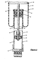
- Figure 2 is a cross-sectional side view of a frequency dependent damper or shock absorber
- Figure 3 is a schematic view of the suspension including the shock absorber of Figure 2 , a booster and an air spring assembly according to the present invention.
- a vehicle 10 includes a rear suspension system 12, a front suspension system 14 and a body 16.
- the rear suspension system 12 includes a pair of independent suspensions 18 supporting a pair of rear wheels 20. Each rear independent suspension 18 is attached to the body 16 by means of a frequency dependent damper or shock absorber 22 and an air spring assembly 24.
- the front suspension system 14 includes a pair of independent suspensions 26 supporting a pair of front wheels 28. Each independent front suspension 26 is attached to the body 16 and includes an integrated shock assembly 30 having the shock absorber 22 and the air spring assembly 24.
- the shock absorbers 22 dampen the relative movement of the unsprung portion (i.e., the front and rear suspension systems 12 and 14) of the vehicle 10 with respect to the sprung portion (i.e., the body 16) of the vehicle 10. While the vehicle 10 has been depicted as a passenger vehicle having independent front and rear suspensions, the shock absorbers 22 and air spring assemblies 24 may be incorporated into other types of vehicles having other types of suspensions. It is also anticipated that the shock absorbers 22 and air spring assemblies 24 may be incorporated into other types of applications, including, but not limited to, vehicles having air springs, leaf springs, non-independent front and/or non-independent rear suspension systems. Further, the term "shock absorber" as used herein is meant to refer to dampers in general and thus includes MacPherson struts, spring seat units, as well as other shock absorber designs known in the art.
- the integrated shock assembly 30 includes the shock absorber 22 and the air spring assembly 24.
- the shock absorber 22 is disclosed in detail in commonly assigned U.S. Patent Application No. 09/778,455, filed February 7, 2001 and published as US-A-2002/0104724 .
- the shock absorber 22 includes a pressure tube 32, a piston assembly 34, a piston rod 36 and a rod guide assembly 38.
- the pressure tube 32 defines a working chamber 40 that is filled with a gas, preferably air, at a specified pressure to act as the damping medium.
- the piston assembly 34 is slidably disposed within the working chamber 40 and divides the working chamber 40 into an upper working chamber 42 and a lower working chamber 44.
- a seal assembly 46 is disposed between the piston assembly 34 and the pressure tube 32 to enable sliding movement of piston assembly 34 within the pressure tube 32 without generating undue frictional forces.
- the seal assembly 46 seals the upper working chamber 42 from the lower working chamber 44.
- the piston rod 36 is attached to the piston assembly 34 and extends through the upper working chamber 42 and through the rod guide assembly 38, which closes the upper end of the pressure tube 32.
- the end of the piston rod 36 opposite to the piston assembly 34 is secured to a sprung portion of the vehicle 10 via an upper mount assembly 48.
- the end of pressure tube 32 opposite to the rod guide assembly 38 is closed by an end cap 50 that is connected to an unsprung portion of the vehicle 10. It is also anticipated that the piston rod 36 can be attached to the unsprung portion of the vehicle 10 and the end cap 50 attached to the sprung portion of the vehicle 10.
- the air spring assembly 24 of the integrated shock assembly 30 comprises a flexible bladder 52 which is secured to the shock absorber 22 using a retainer 54 and which is secured to the upper mount assembly 48 by a retainer 56.
- the bladder 52 defines chamber 58 that contains pressurized gas for supporting the body 16 of the vehicle 10.
- the chamber 58 of the bladder 52 and the lower working chamber 44 of the shock absorber 22 are pressure-dependent on one another through a booster 60.
- the booster 60 boosts the air pressure within the lower working chamber 44 of the shock absorber 22.
- the booster 60 includes a housing 62 and a piston assembly 64 slidably disposed therein.
- the housing 62 defines a working chamber 66 that is separated into a first working chamber 68, a second or intermediate working chamber 70 and a third working chamber 72 by the piston assembly 64.
- the piston assembly 64 includes a large diameter piston 74 slidably disposed in a first section 76 of the housing 62 and a small diameter piston 78 slidably disposed within a second section 80 of the housing 62.
- the large diameter piston 74 is connected to the small diameter piston 78 by a piston rod 82.
- the first working chamber 68 is in fluid communication with the chamber 58 of the air spring assembly 24 through a conduit 84.
- the intermediate working chamber 70 is in fluid communication with atmosphere through a vent 86.
- the third working chamber 72 is in fluid communication with the lower working chamber 44 of the shock absorber 22 through a conduit 88.
- a restrictor 90 is optionally provided to restrict fluid flow through the conduit 84. The restrictor 90 inhibits dynamic interaction between the air spring assembly 24 and the shock absorber 22.
- An end stop 92 is optionally provided to limit sliding movement of the piston assembly 64. The end stop limits the static pressure within the shock absorber 22 to provide a non-linear relationship between the pressure in the air spring assembly 24 and the shock absorber 22.
- the air pressure within the air spring assembly 24 is lower than the pressure within the shock absorber 22.
- the booster 60 enables boosting of the air pressure within the air spring assembly- 22 and adjustment of the power dissipation ability of the shock absorber 22 based on the load of the vehicle 10.
- F LOAD acts on the air spring assembly 24 until a static state is achieved.
- F LOAD increases the pressure (P ASA ) within the air spring assembly 24.
- P ASA acts across the surface area (A LDP ) of the large diameter piston 74 applying a force (F LDP ) and inducing movement of the large diameter piston 74.
- the large diameter piston 74 moves until the static state is achieved.
- the booster 60 between the air spring assembly 24 and the shock absorber 22 enables a load dependent shock absorber 22. More specifically, the power dissipated by the shock absorber 22 is a function of the static pressure therewithin. The air pressure within the air spring assembly 24 is proportional to the load of the vehicle 20. The booster 60 enables use of the air pressure within the air spring assembly 24 to adapt the pressure within the shock absorber 22.
Landscapes
- Engineering & Computer Science (AREA)
- Mechanical Engineering (AREA)
- General Engineering & Computer Science (AREA)
- Vehicle Body Suspensions (AREA)
- Fluid-Damping Devices (AREA)
Applications Claiming Priority (2)
| Application Number | Priority Date | Filing Date | Title |
|---|---|---|---|
| US10/666,472 US6814347B1 (en) | 2003-09-19 | 2003-09-19 | Booster to adapt air spring pressure for FDD shock absorber |
| PCT/US2004/029219 WO2005032861A2 (en) | 2003-09-19 | 2004-09-08 | Booster to adapt air spring pressure for fdd shock absorber |
Publications (3)
| Publication Number | Publication Date |
|---|---|
| EP1664576A2 EP1664576A2 (en) | 2006-06-07 |
| EP1664576A4 EP1664576A4 (en) | 2006-11-29 |
| EP1664576B1 true EP1664576B1 (en) | 2010-01-27 |
Family
ID=33311144
Family Applications (1)
| Application Number | Title | Priority Date | Filing Date |
|---|---|---|---|
| EP04783460A Expired - Fee Related EP1664576B1 (en) | 2003-09-19 | 2004-09-08 | Booster to adapt air spring pressure for fdd shock absorber |
Country Status (6)
| Country | Link |
|---|---|
| US (1) | US6814347B1 (zh) |
| EP (1) | EP1664576B1 (zh) |
| CN (1) | CN100422590C (zh) |
| BR (1) | BRPI0414517A (zh) |
| DE (1) | DE602004025362D1 (zh) |
| WO (1) | WO2005032861A2 (zh) |
Families Citing this family (13)
| Publication number | Priority date | Publication date | Assignee | Title |
|---|---|---|---|---|
| US7083163B2 (en) * | 2003-09-19 | 2006-08-01 | Tenneco Automotive Operating Company Inc. | Booster with spring to adapt air spring pressure for load dependent shock absorber |
| US20060231360A1 (en) * | 2005-04-15 | 2006-10-19 | A-Pro Tech Co., Ltd. | Pneumatic shock absorber with an ancillary air chamber |
| EP2282901A1 (en) * | 2008-04-30 | 2011-02-16 | Bombardier Recreational Products Inc. | Adjustable height suspension system |
| DE102008030405A1 (de) * | 2008-06-26 | 2009-12-31 | Hydac Electronic Gmbh | Druckübersetzungsvorrichtung und ihre Verwendung in einer Aktuatorsteuervorrichtung |
| US8967648B2 (en) * | 2009-03-12 | 2015-03-03 | Arvinmeritor Technology, Llc | Continuous force control for dual air spring configuration |
| US8701846B2 (en) * | 2009-08-26 | 2014-04-22 | Tenneco Automotive Operating Company Inc | Inverted strut comprising an air damper combined with a hydraulic stop |
| CN102294945B (zh) * | 2010-06-25 | 2013-06-12 | 罗小洪 | 车辆空气悬架减震装置 |
| CN102278403A (zh) * | 2011-07-12 | 2011-12-14 | 胡培培 | 一种空气弹簧系统 |
| DE102012214569B3 (de) * | 2012-08-16 | 2013-10-31 | Ford Global Technologies, Llc | Luftfeder- und Dämpfereinheit mit Höhenverstellung |
| CN103241091B (zh) * | 2013-05-23 | 2016-01-27 | 江苏大学 | 一种带多级自增压机构的空气弹簧闭环气路系统 |
| US11173982B2 (en) * | 2017-08-04 | 2021-11-16 | Joshua J. Angell | Active air spring |
| US10589591B2 (en) | 2018-02-23 | 2020-03-17 | Tenneco Automotive Operating Company Inc. | Active damper system actuator arrangement |
| CN109882323B (zh) * | 2019-02-22 | 2020-01-07 | 常熟理工学院 | 一种可回收压缩空气的发动机增压换气装置及其控制方法 |
Family Cites Families (8)
| Publication number | Priority date | Publication date | Assignee | Title |
|---|---|---|---|---|
| DE1680679A1 (de) * | 1965-12-17 | 1970-03-12 | Fichtel & Sachs Ag | Hydropneumatische Federung |
| USRE27883E (en) * | 1966-02-23 | 1974-01-15 | Suspension system for vehicles | |
| NL8902974A (nl) * | 1989-12-01 | 1991-07-01 | Weweler Nv | Voertuig met asophanginrichting met gasvering en besturingssysteem daarvoor. |
| US5052712A (en) * | 1990-03-19 | 1991-10-01 | Raidel John E | Torque beam, equalized pneumatic and hydraulic axle suspension |
| JP4062645B2 (ja) * | 1998-08-20 | 2008-03-19 | ヤマハ発動機株式会社 | 車両用懸架装置 |
| DE19940198C1 (de) * | 1999-08-25 | 2001-02-01 | Continental Ag | Verfahren zur Regelung eines Systems enthaltend eine Luftfeder und einen dazu parallel geschalteten regelbaren Stoßdämpfer |
| DE10014467C1 (de) * | 2000-03-23 | 2001-10-31 | Mannesmann Sachs Ag | Luftfeder mit tragdruckabhängig verstellbarem Schwingungsdämpfer |
| US7070028B2 (en) | 2001-02-07 | 2006-07-04 | Tenneco Automotive Operating Company Inc. | Frequency dependent damper |
-
2003
- 2003-09-19 US US10/666,472 patent/US6814347B1/en not_active Expired - Fee Related
-
2004
- 2004-09-08 DE DE602004025362T patent/DE602004025362D1/de active Active
- 2004-09-08 WO PCT/US2004/029219 patent/WO2005032861A2/en active Application Filing
- 2004-09-08 EP EP04783460A patent/EP1664576B1/en not_active Expired - Fee Related
- 2004-09-08 BR BRPI0414517-8A patent/BRPI0414517A/pt not_active IP Right Cessation
- 2004-09-08 CN CNB2004800302059A patent/CN100422590C/zh not_active Expired - Fee Related
Also Published As
| Publication number | Publication date |
|---|---|
| CN100422590C (zh) | 2008-10-01 |
| EP1664576A4 (en) | 2006-11-29 |
| WO2005032861A3 (en) | 2005-09-29 |
| WO2005032861A2 (en) | 2005-04-14 |
| US6814347B1 (en) | 2004-11-09 |
| EP1664576A2 (en) | 2006-06-07 |
| BRPI0414517A (pt) | 2006-11-07 |
| DE602004025362D1 (de) | 2010-03-18 |
| CN1867784A (zh) | 2006-11-22 |
Similar Documents
| Publication | Publication Date | Title |
|---|---|---|
| EP1663678B1 (en) | Booster with spring to adapt air spring pressure for load dependent shock absorber | |
| US7950506B2 (en) | Semi third tube design | |
| US7216747B2 (en) | Amplitude controlled orifice valving | |
| JP4890272B2 (ja) | 気体式のショックアブソーバのロッドガイド及びシールシステム | |
| US6460664B1 (en) | Independently tunable variable bleed orifice | |
| US6581733B2 (en) | Acceleration sensitive damping for automotive dampers | |
| EP1664576B1 (en) | Booster to adapt air spring pressure for fdd shock absorber | |
| US20090057079A1 (en) | Disc spring intake | |
| JP2016531039A (ja) | 復圧式受動および能動サスペンション | |
| US7070028B2 (en) | Frequency dependent damper | |
| US7073643B2 (en) | Compensated rod for a frequency dependent damper shock absorber | |
| JPS63159119A (ja) | サスペンション装置および流体シリンダ装置 | |
| US6802404B1 (en) | Electro-rheological or magneto-rheological controlled hydraulic restriction | |
| EP1664581B1 (en) | Shock absorber | |
| JP3609964B2 (ja) | ダンパ |
Legal Events
| Date | Code | Title | Description |
|---|---|---|---|
| PUAI | Public reference made under article 153(3) epc to a published international application that has entered the european phase |
Free format text: ORIGINAL CODE: 0009012 |
|
| 17P | Request for examination filed |
Effective date: 20060316 |
|
| AK | Designated contracting states |
Kind code of ref document: A2 Designated state(s): DE FR GB |
|
| A4 | Supplementary search report drawn up and despatched |
Effective date: 20061102 |
|
| RIC1 | Information provided on ipc code assigned before grant |
Ipc: B60G 11/27 20060101ALI20061026BHEP Ipc: B60G 13/10 20060101ALI20061026BHEP Ipc: B60G 15/14 20060101ALI20061026BHEP Ipc: B60G 17/08 20060101AFI20061026BHEP |
|
| DAX | Request for extension of the european patent (deleted) | ||
| RBV | Designated contracting states (corrected) |
Designated state(s): DE FR GB |
|
| 17Q | First examination report despatched |
Effective date: 20070205 |
|
| GRAP | Despatch of communication of intention to grant a patent |
Free format text: ORIGINAL CODE: EPIDOSNIGR1 |
|
| GRAS | Grant fee paid |
Free format text: ORIGINAL CODE: EPIDOSNIGR3 |
|
| GRAA | (expected) grant |
Free format text: ORIGINAL CODE: 0009210 |
|
| AK | Designated contracting states |
Kind code of ref document: B1 Designated state(s): DE FR GB |
|
| REG | Reference to a national code |
Ref country code: GB Ref legal event code: FG4D |
|
| REF | Corresponds to: |
Ref document number: 602004025362 Country of ref document: DE Date of ref document: 20100318 Kind code of ref document: P |
|
| PLBE | No opposition filed within time limit |
Free format text: ORIGINAL CODE: 0009261 |
|
| STAA | Information on the status of an ep patent application or granted ep patent |
Free format text: STATUS: NO OPPOSITION FILED WITHIN TIME LIMIT |
|
| 26N | No opposition filed |
Effective date: 20101028 |
|
| GBPC | Gb: european patent ceased through non-payment of renewal fee |
Effective date: 20100908 |
|
| REG | Reference to a national code |
Ref country code: FR Ref legal event code: ST Effective date: 20110531 |
|
| PG25 | Lapsed in a contracting state [announced via postgrant information from national office to epo] |
Ref country code: FR Free format text: LAPSE BECAUSE OF NON-PAYMENT OF DUE FEES Effective date: 20100930 |
|
| PG25 | Lapsed in a contracting state [announced via postgrant information from national office to epo] |
Ref country code: GB Free format text: LAPSE BECAUSE OF NON-PAYMENT OF DUE FEES Effective date: 20100908 |
|
| PGFP | Annual fee paid to national office [announced via postgrant information from national office to epo] |
Ref country code: DE Payment date: 20120921 Year of fee payment: 9 |
|
| REG | Reference to a national code |
Ref country code: DE Ref legal event code: R119 Ref document number: 602004025362 Country of ref document: DE Effective date: 20140401 |
|
| PG25 | Lapsed in a contracting state [announced via postgrant information from national office to epo] |
Ref country code: DE Free format text: LAPSE BECAUSE OF NON-PAYMENT OF DUE FEES Effective date: 20140401 |