EP1664516B1 - Automatischer dekompressionsmechanismus mit einem merkmal zur verhinderung einer unbeabsichtigten ausserbetriebsetzung während motorabschaltung - Google Patents
Automatischer dekompressionsmechanismus mit einem merkmal zur verhinderung einer unbeabsichtigten ausserbetriebsetzung während motorabschaltung Download PDFInfo
- Publication number
- EP1664516B1 EP1664516B1 EP04781620A EP04781620A EP1664516B1 EP 1664516 B1 EP1664516 B1 EP 1664516B1 EP 04781620 A EP04781620 A EP 04781620A EP 04781620 A EP04781620 A EP 04781620A EP 1664516 B1 EP1664516 B1 EP 1664516B1
- Authority
- EP
- European Patent Office
- Prior art keywords
- shaft
- cam lobe
- cam
- release mechanism
- compression release
- Prior art date
- Legal status (The legal status is an assumption and is not a legal conclusion. Google has not performed a legal analysis and makes no representation as to the accuracy of the status listed.)
- Expired - Lifetime
Links
- 230000007246 mechanism Effects 0.000 title claims abstract description 39
- 230000006835 compression Effects 0.000 title claims abstract description 37
- 238000007906 compression Methods 0.000 title claims abstract description 37
- 238000000034 method Methods 0.000 claims description 10
- 125000006850 spacer group Chemical group 0.000 claims description 5
- 230000000717 retained effect Effects 0.000 claims description 3
- 239000000463 material Substances 0.000 claims description 2
- 230000002159 abnormal effect Effects 0.000 claims 1
- 239000007769 metal material Substances 0.000 claims 1
- 239000012254 powdered material Substances 0.000 claims 1
- 238000002485 combustion reaction Methods 0.000 abstract description 7
- 230000006872 improvement Effects 0.000 description 4
- 230000001419 dependent effect Effects 0.000 description 2
- 239000007858 starting material Substances 0.000 description 2
- 230000009471 action Effects 0.000 description 1
- 230000000903 blocking effect Effects 0.000 description 1
- 238000010276 construction Methods 0.000 description 1
- 230000003993 interaction Effects 0.000 description 1
- 238000005461 lubrication Methods 0.000 description 1
- 230000013011 mating Effects 0.000 description 1
- 230000004048 modification Effects 0.000 description 1
- 238000012986 modification Methods 0.000 description 1
- 239000012255 powdered metal Substances 0.000 description 1
- 239000011435 rock Substances 0.000 description 1
- 230000007704 transition Effects 0.000 description 1
Images


Classifications
-
- F—MECHANICAL ENGINEERING; LIGHTING; HEATING; WEAPONS; BLASTING
- F01—MACHINES OR ENGINES IN GENERAL; ENGINE PLANTS IN GENERAL; STEAM ENGINES
- F01L—CYCLICALLY OPERATING VALVES FOR MACHINES OR ENGINES
- F01L13/00—Modifications of valve-gear to facilitate reversing, braking, starting, changing compression ratio, or other specific operations
- F01L13/08—Modifications of valve-gear to facilitate reversing, braking, starting, changing compression ratio, or other specific operations for decompression, e.g. during starting; for changing compression ratio
- F01L13/085—Modifications of valve-gear to facilitate reversing, braking, starting, changing compression ratio, or other specific operations for decompression, e.g. during starting; for changing compression ratio the valve-gear having an auxiliary cam protruding from the main cam profile
-
- F—MECHANICAL ENGINEERING; LIGHTING; HEATING; WEAPONS; BLASTING
- F01—MACHINES OR ENGINES IN GENERAL; ENGINE PLANTS IN GENERAL; STEAM ENGINES
- F01L—CYCLICALLY OPERATING VALVES FOR MACHINES OR ENGINES
- F01L1/00—Valve-gear or valve arrangements, e.g. lift-valve gear
- F01L1/02—Valve drive
- F01L1/026—Gear drive
-
- F—MECHANICAL ENGINEERING; LIGHTING; HEATING; WEAPONS; BLASTING
- F01—MACHINES OR ENGINES IN GENERAL; ENGINE PLANTS IN GENERAL; STEAM ENGINES
- F01L—CYCLICALLY OPERATING VALVES FOR MACHINES OR ENGINES
- F01L1/00—Valve-gear or valve arrangements, e.g. lift-valve gear
- F01L1/12—Transmitting gear between valve drive and valve
- F01L1/14—Tappets; Push rods
- F01L1/146—Push-rods
-
- F—MECHANICAL ENGINEERING; LIGHTING; HEATING; WEAPONS; BLASTING
- F01—MACHINES OR ENGINES IN GENERAL; ENGINE PLANTS IN GENERAL; STEAM ENGINES
- F01L—CYCLICALLY OPERATING VALVES FOR MACHINES OR ENGINES
- F01L1/00—Valve-gear or valve arrangements, e.g. lift-valve gear
- F01L1/12—Transmitting gear between valve drive and valve
- F01L1/18—Rocking arms or levers
- F01L1/181—Centre pivot rocking arms
-
- F—MECHANICAL ENGINEERING; LIGHTING; HEATING; WEAPONS; BLASTING
- F01—MACHINES OR ENGINES IN GENERAL; ENGINE PLANTS IN GENERAL; STEAM ENGINES
- F01L—CYCLICALLY OPERATING VALVES FOR MACHINES OR ENGINES
- F01L2301/00—Using particular materials
Definitions
- the present invention relates to internal combustion engines and, more particularly, to automatic compression release mechanisms employed in internal combustion engines.
- Automatic compression release mechanisms are employed in internal combustion engines to provide for improved engine performance at a variety of engine speeds.
- Such mechanisms typically include a component which is actuated based upon engine speed, that varies an exterior surface characteristic of a cam lobe along which mating valve train components actuate exhaust and/or intake valves of the engine.
- a protrusion is created on the cam lobe such that the exhaust valve opens slightly during the compression stroke of the engine.
- the reduced compression caused by this "low speed orientation” reduces the effort to start the engine.
- engine speeds are higher, such as during normal operation or idling, the protrusion is eliminated such that the exhaust valve remains closed during the compression stroke of the engine. This "normal speed orientation" maximizes engine power.
- Automatic compression release mechanisms of this type often employ a weight assembly that is rotatably affixed to a portion of the camshaft such as a cam gear. As the camshaft rotates, centrifugal forces acting on the weight cause the weight to move radially outwards, away from the camshaft axis. However, the weight is typically biased by a spring towards the camshaft so that when the engine is at low speeds, the weight is pulled inward toward the camshaft. Because the movement of the weight is dependent upon the rotational speed of the camshaft, the movement of the weight can be used to govern components associated with the cam lobe to produce the desired speed-dependent variation in cam lobe shape.
- these components include a contoured shaft having a recessed side and an unrecessed side, which is coupled to a weight.
- the contoured shaft is disposed in a notch formed in the surface of the cam lobe, and when the weight is disposed radially inwards at low engine speed, the unrecessed side of the contoured shaft extends outward beyond the exterior surface of the cam lobe producing a protrusion.
- the recessed side of the contoured shaft faces outward and the protrusion on the cam lobe is largely or entirely eliminated.
- the cam gear can be molded out of plastic or die cast as a single piece.
- the cam lobe can be integrally formed as part of the cam gear, or at least fixedly attached to the cam gear.
- U.S. Patent No. 3,362,390, to Francis Esty for instance relates to an automatic compression release for an internal combustion engine having a cam mechanism and an exhaust valve with a valve lifter.
- the compression release includes a latch rotor pin and a latch rotor pin turning the mechanism responsive to engine speed to selectively rotate the pin and an eccentric part on the end of the pin above and below the cam.
- the eccentric part is above the cam so as to engage the valve lifter when the rotor pin is one position at low engine speeds and is below the cam so as not to engage the valve lifter at high engine speeds.
- the present invention provides an automatic compression release mechanism (ACR) having a weight assembly for rotating a contoured shaft in a notch of a cam lobe between a low speed orientation in which the contoured shaft presents a first surface that protrudes above a cam lobe surface at normal speed orientation in which the contoured shaft presents a second surface that is substantially flush with the cam lobe surface, characterized by a step formed in the notch of the cam lobe which interacts with the contoured shaft to resist rotation of the contoured shaft from low speed orientation to the normal speed orientation when the cam lobe moves in a first direction of rotation during engine shut down that is opposite a second direction of rotation of the cam lobe during normal engine operation.
- ACR automatic compression release mechanism
- the present invention also provides a method of operating a camshaft assembly, the method characterized by the steps of decelerating a rotational speed of the camshaft assembly from a first speed to a second speed, wherein the camshaft assembly is rotating in a first rotational direction; as the camshaft assembly is decelerating, rotating a shaft of an actuator assembly of the camshaft assembly as that a protuberance appears on the cam lobe; and receiving an axially extending edge of the shaft adjacent to an axially extending step formed in the recess, wherein in at least one operational situation the shaft is prevented from rotating in a manner that would cause the edge to pass by the step.
- the present invention is an improvement to an automatic compression release mechanism which prevents it from becoming disabled during engine shut down. More specifically, the improvement is a step formed in the notch which rotatably supports the contoured shaft along the surface of the cam lobe. This step blocks or prevents, the contoured shaft from being rotated by the cam follower when the engine rotates in reverse direction during shut down.
- the present invention relates to an improvement in an automatic compression release mechanism having a weight assembly for rotating a contoured shaft in a notch of a cam lobe between a low speed orientation in which the contoured shaft presents a first surface that protrudes above a cam lobe surface and a normal speed orientation in which the contoured shaft presents a second surface that is substantially flush with the cam lobe surface.
- the improvement includes a step formed in the notch of the cam lobe which interacts with the contoured shaft to resist rotation of the contoured shaft from the low speed orientation to the normal speed orientation when the cam lobe moves in a first direction of rotation during engine shut down that is opposite a second direction of rotation of the cam lobe during normal engine operation.
- the present invention additionally relates to a camshaft assembly that includes a cam lobe having a recess, a cam gear coupled to the cam lobe, and an actuator assembly including a weight and a shaft coupled to one another.
- the actuator assembly is supported in relation to the cam lobe so that the shaft extends into the recess.
- the shaft of the actuator assembly is configured so that during low speed rotation of the cam lobe a protuberance formed by a portion of the shaft extends out of the recess beyond a perimeter of the cam lobe, and during normal speed rotation of the cam lobe the protuberance is at least one of reduced and eliminated.
- the recess includes two curved surfaces that are connected by a step surface, and the step surface restricts rotational movement of the shaft at least some of the time.
- the present invention further relates to a method of operating a camshaft assembly.
- the method includes decelerating a rotational speed of the camshaft assembly from a first speed to a second speed, where the camshaft assembly is rotating in a first rotational direction and, as the camshaft assembly is decelerating, rotating a shaft of an actuator assembly of the camshaft assembly within a recess of a cam lobe of the camshaft assembly, so that a protuberance appears on the cam lobe.
- the method additionally includes receiving an axially extending edge of the shaft adjacent to an axially extending step formed in the recess, where in at least one operational situation the shaft is prevented from rotating in a manner that would cause the edge to pass by the step.
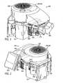
- Fig. 1 is a first perspective view of a single cylinder engine, taken from a side of the engine on which are located a starter and cylinder head;
- Fig. 2 is a second perspective view of the single cylinder engine of Fig. 1 , taken from a side of the engine on which are located an air cleaner and oil filter;
- Fig. 3 is a third perspective view of the single cylinder engine of Fig. 1 , in which certain parts of the engine have been removed to reveal additional internal parts of the engine;
- Fig. 4 is a fourth perspective view of the single cylinder engine of Fig. 1 , in which certain parts of the engine have been removed to reveal additional internal parts of the engine;
- Fig. 5 is fifth perspective view of portions of the single cylinder engine of Fig. 1 , in which a top of the crankcase has been removed to reveal an interior of the crankcase;
- Fig. 6 is a sixth perspective view of portions of the single cylinder engine of Fig. 1 , in which the top of the crankcase is shown exploded from the bottom of the crankcase;
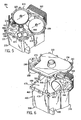
- Fig. 7 is a top view of the single cylinder engine of Fig. 1 , showing internal components of the engine;
- Fig. 8 is a perspective view of components of a valve train of the single cylinder engine of Fig. 1 ;
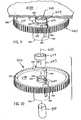
- Fig. 9 is a perspective view of a camshaft, cam gear and automatic compression release (ACR) mechanism implemented in the engine of Fig. 1 ;
- Fig. 10 is a perspective view of the camshaft, cam gear and ACR mechanism of Fig. 9 , with the ACR mechanism exploded from the cam gear;
- Fig. 11 is a view in cross-section through the cam lobe showing the ACR mechanism in its normal engine speed orientation
- Fig. 12 is a view in cross-section through the cam lobe showing the ACR mechanism in its low speed orientation
- Fig. 13 is a view in cross-section through the cam lobe showing the ACR mechanism during engine shut down
- Fig. 14 is a perspective view of the cam lobe showing the recess which receives the ACR.
- a single cylinder, 4-stroke, internal combustion engine 100 includes a crankcase 110 and a blower housing 120, inside of which are a fan 130 and a flywheel 140.
- the engine 100 further includes a starter 150, a cylinder 160, a cylinder head 170, and a rocker arm cover 180. Attached to the cylinder head 170 are an air exhaust port 190 shown in Fig. 1 and an air intake port 200 shown in Fig. 2 .
- a piston 210 moves back and forth within the cylinder 160 towards and away from the cylinder head 170.
- the movement of the piston 210 in turn causes rotation of a crankshaft 220 (see Fig. 7 ), as well as rotation of the fan 130 and the flywheel 140, which are coupled to the crankshaft.
- the rotation of the fan 130 cools the engine, and the rotation of the flywheel 140, causes a relatively constant rotational momentum to be maintained.
- the engine 100 further includes an air filter 230 coupled to the air intake port 200, which filters the air required by the engine prior to the providing of the air to the cylinder head 170.
- the air provided to the air intake port 200 is communicated into the cylinder 160 by way of the cylinder head 170, and exits the engine by flowing from the cylinder through the cylinder head and then out of the air exhaust port 190.
- the inflow and outflow of air into and out of the cylinder 160 by way of the cylinder head 170 is governed by an input (intake) valve 240 and an output (exhaust) valve 250, respectively (see Fig. 8 ). Also as shown in Fig.
- the engine 100 includes an oil filter 260 through which the oil for the engine 100 is passed and filtered.
- the oil filter 260 is coupled to the crankcase 110 by way of incoming and outgoing lines 270, 280, respectively, whereby pressurized oil is provided into the oil filter and then is returned from the oil filter to the crankcase.
- the engine 100 is shown with the blower housing 120 removed to expose a top 290 of the crankcase 110.
- a coil 300 is shown that generates an electric current based upon rotation of the fan 130 and/or the flywheel 140, which together operate as a magneto.
- the top 290 of the crankcase 110 has a pair of lobes 310 that cover a pair of cam gears 320 (see Figs. 5 and 7-8 ).
- the fan 130 and the flywheel 140 are above the top 290 of the crankcase 110.
- Fig. 4 the fan 130 and the flywheel 140 are above the top 290 of the crankcase 110.
- FIG. 4 shows the engine 100 without the rocker arm cover 180, to more clearly reveal a pair of tubes 330 through which extend a pair of respective push rods 340.
- the push rods 340 extend between a pair of respective rocker arms 350 and a pair of cams 360 (see Fig. 8 ) within the crankcase 110, as discussed further below.
- the engine 100 is shown with the top 290 of the crankcase 110 removed from a bottom 370 of the crankcase 110 to reveal an interior 380 of the crankcase. Additionally in Figs. 5 and 6 , the engine 100 is shown in cut-away to exclude portions of the engine that extend beyond the cylinder 160 such as the cylinder head 170. With respect to Fig. 6 , the top 290 of the crankcase 110 is shown above the bottom 370 of the crankcase in an exploded view. In this embodiment, the bottom 370 includes not only a floor 390 of the crankcase, but also all four side walls 400 of the crankcase, while the top 290 only acts as the roof of the crankcase.
- the top 290 and bottom 370 are manufactured as two separate pieces such that, in order to open the crankcase 110, one physically removes the top from the bottom. Also, as shown in Fig. 5 , the pair of gears 320 within the crankcase 110 are integrally formed as part of, or at least supported by, respective camshafts 410, which in turn are supported by the bottom 370 of the crankcase 110.
- a top view of the engine 100 (with the top 290 of the crankcase 110 removed) is provided in which additional internal components of the engine are shown.
- Fig. 7 shows the piston 210 within the cylinder 160 to be coupled to the crankshaft 220 by a connecting rod 420.
- the crankshaft 220 is in turn coupled to a rotating counterweight 430 and reciprocal weights 440, which balance the forces exerted upon the crankshaft 220 by the piston 210.
- the crankshaft 220 further is in contact with each of the gears 320, and thus communicates rotational motion to the gears.
- the camshafts 410 upon which the cam gears 320 are supported are capable of communicating oil from the floor of the crankcase 110 upward to the gears 320.
- the incoming line 270 to the oil filter 260 is coupled to one of the camshafts 410 to receive oil, while the outgoing line 280 from the oil filter is coupled to the crankshaft 220 to provide lubrication thereto.
- Fig. 7 further shows a spark plug 450 located on the cylinder head 170, which provides sparks during power strokes of the engine to cause combustion to occur within the cylinder 160.
- the electrical energy for the spark plug 450 is provided by the coil 300 (see Fig. 3 ).
- valve train 460 includes cam gears 320 driven by camshafts 410 and also includes the cam lobes 360 disposed underneath the respective gears 320 and around respective camshafts 410.
- Cam follower arms 470 are rotatably mounted to the crankcase 110 and extend to rest upon the respective cam lobes 360.
- the push rods 340 in turn rest upon the respective cam follower arms 470 and as the cam lobes 360 rotate, the push rods 340 are forced outward away from the respective camshafts 410 by the cam follower arms 470 as they follow the contour of their respective cam lobes 360.
- rocker arms 350 This causes the rocker arms 350 to rock or rotate, and consequently causes the respective valves 240 and 250 to open and close at the proper times during the engine cycle.
- a pair of springs 480, 490 positioned between the cylinder head 170 and the rocker arms 350 apply a bias force to the rocker arms in a direction tending to close the valves 240,250.
- the push rods 340 are also forced against the cam follower arms 470 and hence against the cam lobes 360.
- the engine 100 is a vertical shaft engine capable of outputting 15-20 horsepower for implementation in a variety of consumer lawn and garden machinery such as lawn mowers.
- the engine 100 can also be implemented as a horizontal shaft engine, be designed to output greater or lesser amounts of power, and/or be implemented in a variety of other types of machines, e.g., snow-blowers.
- the particular arrangement of parts within the engine 100 can vary from those shown and discussed above.
- the cam lobes 360 could be located above the gears 320 rather than underneath the gears.
- each cam gear 320 is disposed directly beneath the top cover 290 of the crankcase.
- a central hub 640 supports each cam gear 320 with respect to its respective cam shaft 410 for rotation about a vertical cam shaft axis 645.
- a web 649 extends radially outward from the hub 640 and supports a circular ring of gear teeth 700.
- the hub 640 and the ring of gear teeth 700 form an annular-shaped recess on the top side of each cam gear 320.
- an automatic compression release (ACR) mechanism is mounted to each of the cam gears (or, in alternate embodiments, one of the cam gears) 320 and disposed in the respective recesses of the cam gears.
- the ACR mechanism associated with each cam gear includes an actuator assembly 510 comprised of an arc-shaped weight 530 and an integrally formed contoured shaft 540.
- the assembly 510 is formed of powdered metal, although it may also be molded from plastic or other materials, or it may be die cast.
- the assembly 510 is rotatably mounted to the cam gear 320 by extending the contoured shaft 540 into and through a hollow tube 550 formed through the cam gear web 649.
- the contoured shaft 540 rotates about an axis 647 that is parallel to the cam shaft axis 645.
- the top end of the contoured shaft 540 is circular in contour and connects to one end of the weight 530. It extends downward through the tube 550 and into an axially directed notch, or recess 580 formed in the cam lobe 360.
- the cam lobe 360 is located beneath the cam gear 320 and the lower end of the contoured shaft 540 is shaped to form a flat recessed surface 620 in its cylindrical surface. This flat surface 620 extends over the axial extent of the cam lobe recess 580 and the contoured shaft 540 has a "D-shaped" cross-section in the recess 580 as shown in Figs 11-13 .
- the flat surface 620 on the contoured shaft 540 faces radially outward and it is substantially flush with the outer surface of the cam lobe 360.
- the contoured shaft 540 is rotated within the recess 580 such that a portion of its D-shaped surface protrudes above the surface of the cam lobe 360. It is this protuberance which pushes upward on the push rods 340 through the cam followers 470 to open the valves 240 and 250 at low engine speed and thereby facilitate easier starting.
- the actuator assembly 510 is biased in its low engine speed orientation by a spring 600.
- One end of the spring 600 wraps around the weight 530 and its other end bears against a pin (not shown) formed on the cam gear 320.
- the spring action produced by two wraps around the top of the contoured shaft 540 biases the weight 530 against the hub 640.
- the rotation of the cam gear 320 causes the actuator assembly 510 to rotate about its axis 647 and move radially outward from the cam shaft axis 645 against the bias spring force to its normal engine speed orientation.
- the actuator assembly 510 is retained in place by an annular-shaped spacer 654.
- the spacer 654 encircles the cam shaft 410 and it fills the gap between the top of the actuator assembly 510 and the bottom surface of the crankcase cover 290.
- the actuator assembly 510 is thus axially retained by the spacer 654 from moving upward. It is trapped in the supporting tube 550 and constrained to rotational movement between its two operating orientations.
- an important aspect of the present invention is the shape of the axially directed recess 580 in the surface of the cam lobe 360.
- the recess 580 extends axially a substantial distance and it forms a trough having two curved surfaces 582 and 583.
- Each curved surface 582 and 583 is shaped to mate with the circular surface of the contoured shaft 540, however, they are offset from each other to form a step 584.
- Fig. 13 when the contoured shaft 540 is in its low engine speed orientation, one edge of its flat surface 620 engages this step 584 and inhibits its rotation to the high speed orientation.
- step 584 is effective in blocking rotation of the actuator assembly to the normal engine speed orientation during engine shut down, it does not hinder the transition to normal engine speed during engine start up.
- the contoured shaft 540 engages the step 584 as shown in Fig. 12 and the protruding shaft 540 relieves compression to assist starting as described above.
- a torque is applied to the contoured shaft 540 by the weight 530 which rotates the shaft 540 against the edge 584.
- the centrifugal force acting on the actuator assembly as a whole lifts the edge of the contoured shaft 540 over the step 584.
- the axial opening in the tube 550 (see Fig. 10 ) must be large enough to allow the contoured shaft 540 to align radially with both curved surfaces 582 and 583.
- step 584 in the cam lobe recess 580 and the edge formed on the contoured shaft 540 by the flat surface 620 thus use the very pressure produced by the cam follower 470 which is the cause of the problem during engine shut down to solve the problem.
- this pressure is not applied for a large portion of each revolution of the cam lobe 360 and normal operation of the automatic compression release mechanism is allowed to occur.
- the present invention thus uses the force which causes the shut down problem to solve the problem.
- another aspect of the invention is the above-described means for fastening a weight and contoured shaft actuator assembly to the cam gear, where the contoured shaft extends through an opening formed in the cam gear and into the aligned notch formed in the cam lobe, and where the weight is free to rotate the contoured shaft about an axis through this opening and is axially constrained therein by a spacer disposed around a cam gear hub and extending radially outward therefrom to intercede between the cover and the weight assembly.
Landscapes
- Engineering & Computer Science (AREA)
- Mechanical Engineering (AREA)
- General Engineering & Computer Science (AREA)
- Valve-Gear Or Valve Arrangements (AREA)
- Valve Device For Special Equipments (AREA)
- Output Control And Ontrol Of Special Type Engine (AREA)
Claims (20)
- Automatischer Dekompressionsmechanismus mit einer Gewichtseinheit zum Drehen einer Profilwelle (540) in einer Kerbe (580) eines Nocken (360) zwischen einer Ausrichtung mit geringer Drehzahl, an der die Profilwelle (540) eine erste Oberfläche präsentiert, die über eine Oberfläche eines Nocken (360) vorsteht, und einer Ausrichtung mit normaler Drehzahl, an der die Profilwelle eine zweite Oberfläche (620) präsentiert, die im Wesentlichen bündig ist mit der Oberfläche des Nocken (360), gekennzeichnet durch:eine Stufe (584), die in der Kerbe (580) des Nocken (360) ausgebildet ist, wobei die Stufe mit der Profilwelle (540) zusammenwirkt, um einer Rotation der Profilwelle (540) aus der Ausrichtung mit geringer Drehzahl an die Ausrichtung mit normaler Drehzahl zu widerstehen, wenn sich der Nocken (360) beim Abschalten des Motors in eine erste Rotationsrichtung bewegt, die entgegengesetzt ist zu einer ersten Rotationsrichtung des Nocken (360) während normalem Motorbetrieb.
- Automatischer Dekompressionsmechanismus nach Anspruch 1, wobei die Profilwelle (540) einen im Wesentlichen D-förmigen Querschnitt aufweist, geformt durch eine gekrümmte Oberfläche (620) und eine flache Oberfläche, die sich an zwei axial ausgerichteten Kanten schneiden.
- Automatischer Dekompressionsmechanismus nach Anspruch 2, wobei die Kerbe (580) durch zwei gekrümmte Oberflächen (582, 583) gebildet wird, die jeweils mit der gekrümmten Oberfläche der Profilwelle (540) zusammenpassen, und wobei die gekrümmten Oberflächen der Kerbe (580) im Verhältnis zueinander versetzt sind, so dass die Stufe (584) in der Kerbe (580) gebildet wird.
- Automatischer Dekompressionsmechanismus nach Anspruch 3, wobei eine der axial ausgerichteten Kanten und ein Teilstück der flachen Oberfläche (620) der Profilwelle (540) zumindest zeitweise an der Stufe (584) ruhen, wenn sich die Profilwelle (540) in der Ausrichtung mit geringer Drehzahl befindet.
- Automatischer Dekompressionsmechanismus nach Anspruch 4, wobei beim Ausüben von Druck auf die Profilwelle (620) durch einen Nockenstößel (470), wenn sich der Nocken (360) in die erste Richtung bewegt, der Druck dazu neigt, die Profilwelle (540) an eine der beiden gekrümmten Oberflächen (582, 583) zu drängen, was dazu dient, dass es verhindert wird, dass sich die Profilwelle (540) so bewegt, dass sie die Stufe (584) überwindet.
- Automatischer Dekompressionsmechanismus nach Anspruch 4, wobei bei einer Bewegung des Nocken (360) in die zweite Richtung und bei einer Beschleunigung des Nocken (360) von einer geringen Drehzahl auf eine normale Drehzahl, die Profilwelle (540) gedreht und über die Stufe (584) angehoben wird.
- Automatischer Dekompressionsmechanismus nach Anspruch 6, wobei die Profilwelle (540) so konfiguriert ist, dass sie in eine Rohrleitung (550) passt, die einen inneren Bereich aufweist, der ausreichend groß ist, so dass er eine radiale Ausrichtung der Profilwelle (540) mit jeder der beiden gekrümmten Oberflächen (582, 583) ermöglicht.
- Automatischer Dekompressionsmechanismus nach Anspruch 1, wobei für die Gewichtseinheit (530) und die Profilwelle (540) mindestens eine der folgenden Eigenschaften aufweist: aus einem pulverförmigen Material gebildet ist; aus einem metallischen Material gebildet ist; aus einem Kunststoff gebildet ist; oder druckgegossen ist.
- Automatischer Dekompressionsmechanismus nach Anspruch 1, wobei:eine Nockensteuerung (320) mit dem Nocken (360) gekoppelt ist; undeine Stelleinheit (510) im Verhältnis zu dem Nocken (360) getragen wird, so dass sich die Welle (540) in die Aussparung (580) erstreckt;wobei die Welle (540) der Stelleinheit (510) so konfiguriert ist, dass sich während einer Rotation mit geringer Drehzahl des Nocken (360) eine durch ein Teilstück der Welle (540) gebildete Protuberanz aus der Aussparung (580) hinaus über einen Perimeter des Nocken (360) erstreckt, und wobei bei einer Rotation mit normaler Drehzahl des Nocken (360) die Protuberanz zumindest reduziert oder nicht vorhanden ist; undwobei die Aussparung (580) zwei gekrümmte Oberflächen (582, 583) aufweist, die durch eine Oberfläche einer Stufe (584) verbunden sind, und wobei die Stufenoberfläche die Drehbewegung der Welle (540) zumindest zeitweise beschränkt.
- Automatischer Dekompressionsmechanismus nach Anspruch 9, wobei die Welle (540) einen im Wesentlichen D-förmigen Querschnitt aufweist, gebildet durch eine gekrümmte Oberfläche und eine flache Oberfläche (620), die sich an zwei axial ausgerichteten Kanten schneiden.
- Automatischer Dekompressionsmechanismus nach Anspruch 10, wobei dieser ferner einen Nockenstößel (470) umfasst, der sich zumindest in Kontakt mit dem Nocken (360) oder mit der Welle (540) befindet.
- Automatischer Dekompressionsmechanismus nach Anspruch 11, wobei beim Ausüben von Druck auf die Welle (620) durch den Nockenstößel (470), wenn sich der Nocken (360) in eine anomale Rotationsrichtung bewegt, die entgegengesetzt zu der normalen Rotationsrichtung verläuft, der Druck dazu neigt, die Profilwelle (540) an eine der beiden gekrümmten Oberflächen (582, 583) zu drängen, was wiederum dazu dient, dass es verhindert wird, dass sich die Profilwelle (540) über die Stufe (584) hinaus dreht.
- Automatischer Dekompressionsmechanismus nach Anspruch 9, wobei dieser ferner eine Trägerstruktur zumindest an dem Nocken (360) oder der Nockensteuerung (320) umfasst, wobei die Stelleinheit (510) durch die Trägerstruktur im Verhältnis zu dem Nocken (360) getragen wird, so dass sich die Welle (540) in die Aussparung (580) des Nocken (360) erstreckt.
- Automatischer Dekompressionsmechanismus nach Anspruch 13, wobei die Trägerstruktur eine Rohrleitung (550) aufweist, die sich durch die Nockensteuerung (320) erstreckt, und wobei die Trägerstruktur die Stelleinheit (510) trägt, so dass das Gewicht (530) entlang einer ersten Seite der Nockensteuerung (320) positioniert wird, und wobei sich die Welle (540) von dem Gewicht (530) durch die Rohrleitung (550) und daraus hinaus über eine zweite Seite der Nockensteuerung (320) und in die Aussparung (580) des Nocken (360) erstreckt.
- Automatischer Dekompressionsmechanismus nach Anspruch 14, wobei dieser ferner einen Abstandshalter (649) umfasst, der um eine zentrale Nabe (640) der Nockensteuerung (320) angeordnet ist und sich von dort radial auswärts erstreckt, so dass er zwischen der Stelleinheit (510) und einem Teilstück des Gehäuses vermittelt, so dass die Welle (540) der Stelleinheit (510) axial in der Rohrleitung (550) und in der Aussparung (580) gehalten wird.
- Automatischer Dekompressionsmechanismus nach Anspruch 9, wobei dieser ferner eine Einrichtung für eine Vorbelastung des Gewichts (530) der Stelleinheit (510) in Richtung eines inneren Teilstücks der Nockensteuerung (320) umfasst, wobei bei hohen Drehzahlen der Nockensteuerung (320) und des Nocken (360) die Zentrifugalkraft bewirkt, dass sich das Gewicht (530) auswärts und von dem inneren Teilstück der Nockensteuerung (320) entgegen einer Vorbelastungskraft bewegt, die durch die Einrichtung für eine Vorbelastung bereitgestellt wird.
- Verfahren zum Betrieb einer Nockenwelleneinheit, wobei das Verfahren durch die folgenden Schritte gekennzeichnet ist:das Herabsetzen einer Drehzahl der Nockenwelleneinheit von einer ersten Drehzahl auf eine zweite Drehzahl, wobei sich die Nockenwelleneinheit in eine erste Drehrichtung dreht;während der Verlangsamung der Nockenwelleneinheit das Drehen einer Welle (540) einer Stelleinheit (510) der Nockenwelleneinheit in einer Aussparung (580) eines Nocken (360) der Nockenwelleneinheit, so dass an dem Nocken (360) eine Protuberanz erscheint; unddas Aufnehmen einer sich axial erstreckenden Kante der Welle (540) angrenzend an eine in der Aussparung (580) ausgebildete, sich axial erstreckende Stufe (584);wobei in mindestens einer Betriebssituation die Rotation der Welle (540) in einer Weise verhindert wird, die es bewirken würde, dass die Kante die Stufe (584) passiert.
- Verfahren nach Anspruch 17, wobei die mindestens eine Betriebssituation eintritt, wenn nach der Verlangsamung der Nockenwelleneinheit die Nockenwelleneinheit beginnt, sich in eine zweite Drehrichtung zu drehen, die entgegengesetzt ist zu der ersten Drehrichtung.
- Verfahren nach Anspruch 17, wobei das Verfahren ferner folgendes umfasst:vor dem Verlangsamen der Drehzahl das Beschleunigen der Drehzahl der Nockenwelleneinheit von der zweiten Drehzahl auf die erste Drehzahl; undwährend der Beschleunigung der Nockenwelleneinheit das Bewirken, dass die Welle (540) der Nockenwelleneinheit (510) der Nockenwelleneinheit sich in der Aussparung (580) des Nocken (360) der Nockenwelleneinheit dreht, so dass die Protuberanz zumindest verringert oder beseitigt wird.
- Verfahren nach Anspruch 17, wobei die Rotation der Welle (540) durch eine Feder (600) bewirkt wird, die ein Gewichtsteilstück der Stelleinheit (510) in Richtung eines inneren Teilstücks der Nockensteuerung (320) vorbelastet.
Applications Claiming Priority (3)
| Application Number | Priority Date | Filing Date | Title |
|---|---|---|---|
| US49643303P | 2003-08-20 | 2003-08-20 | |
| PCT/US2004/026967 WO2005019634A2 (en) | 2003-08-20 | 2004-08-19 | Automatic compression release mechanism including feature to prevent unintentional disablement during engine shutdown |
| US10/921,531 US6938600B2 (en) | 2003-08-20 | 2004-08-19 | Automatic compression release mechanism including feature to prevent unintentional disablement during engine shutdown |
Publications (3)
| Publication Number | Publication Date |
|---|---|
| EP1664516A2 EP1664516A2 (de) | 2006-06-07 |
| EP1664516A4 EP1664516A4 (de) | 2008-11-26 |
| EP1664516B1 true EP1664516B1 (de) | 2010-08-11 |
Family
ID=34221407
Family Applications (1)
| Application Number | Title | Priority Date | Filing Date |
|---|---|---|---|
| EP04781620A Expired - Lifetime EP1664516B1 (de) | 2003-08-20 | 2004-08-19 | Automatischer dekompressionsmechanismus mit einem merkmal zur verhinderung einer unbeabsichtigten ausserbetriebsetzung während motorabschaltung |
Country Status (8)
| Country | Link |
|---|---|
| US (1) | US6938600B2 (de) |
| EP (1) | EP1664516B1 (de) |
| AT (1) | ATE477403T1 (de) |
| AU (1) | AU2004267481B2 (de) |
| DE (1) | DE602004028635D1 (de) |
| MX (1) | MXPA06001929A (de) |
| NZ (1) | NZ545394A (de) |
| WO (1) | WO2005019634A2 (de) |
Families Citing this family (5)
| Publication number | Priority date | Publication date | Assignee | Title |
|---|---|---|---|---|
| WO2006110317A2 (en) * | 2005-04-08 | 2006-10-19 | Mtd Products, Inc. | Automatic decompression mechanism for an engine |
| US8970205B2 (en) * | 2011-03-15 | 2015-03-03 | Electric Torque Machines Inc | Adjustable hall effect sensor system |
| JP6109610B2 (ja) * | 2013-03-18 | 2017-04-05 | 本田技研工業株式会社 | 内燃機関のデコンプ機構 |
| WO2018031010A1 (en) * | 2016-08-10 | 2018-02-15 | Briggs & Stratton Corporation | Centrifugal cam gear oil filter for internal combustion engine |
| WO2019187079A1 (ja) * | 2018-03-30 | 2019-10-03 | 本田技研工業株式会社 | エンジン |
Family Cites Families (10)
| Publication number | Priority date | Publication date | Assignee | Title |
|---|---|---|---|---|
| US3362390A (en) * | 1966-02-09 | 1968-01-09 | Wisconsin Motor Corp | Automatic compression release |
| JPS61178011U (de) * | 1985-04-25 | 1986-11-06 | ||
| US4696266A (en) * | 1985-05-14 | 1987-09-29 | Fuji Jukogyo Kabushiki Kaisha | Decompression apparatus for engines |
| US5197422A (en) * | 1992-03-19 | 1993-03-30 | Briggs & Stratton Corporation | Compression release mechanism and method for assembling same |
| US5957101A (en) * | 1997-07-09 | 1999-09-28 | Kohler Co. | Automatic compression release mechanism for an internal combustion engine |
| US6269786B1 (en) * | 1999-07-21 | 2001-08-07 | Tecumseh Products Company | Compression release mechanism |
| US6439187B1 (en) * | 1999-11-17 | 2002-08-27 | Tecumseh Products Company | Mechanical compression release |
| US6536393B2 (en) * | 2000-09-11 | 2003-03-25 | Tecumseh Products Company | Mechanical compression and vacuum release |
| US20040003791A1 (en) * | 2002-07-08 | 2004-01-08 | Giuseppe Ghelfi | Compression release mechanism |
| US6672269B1 (en) * | 2002-07-18 | 2004-01-06 | Kohler Co. | Automatic compression release mechanism |
-
2004
- 2004-08-19 EP EP04781620A patent/EP1664516B1/de not_active Expired - Lifetime
- 2004-08-19 WO PCT/US2004/026967 patent/WO2005019634A2/en not_active Ceased
- 2004-08-19 NZ NZ545394A patent/NZ545394A/en unknown
- 2004-08-19 AU AU2004267481A patent/AU2004267481B2/en not_active Ceased
- 2004-08-19 DE DE602004028635T patent/DE602004028635D1/de not_active Expired - Lifetime
- 2004-08-19 MX MXPA06001929A patent/MXPA06001929A/es active IP Right Grant
- 2004-08-19 US US10/921,531 patent/US6938600B2/en not_active Expired - Lifetime
- 2004-08-19 AT AT04781620T patent/ATE477403T1/de not_active IP Right Cessation
Also Published As
| Publication number | Publication date |
|---|---|
| AU2004267481A1 (en) | 2005-03-03 |
| ATE477403T1 (de) | 2010-08-15 |
| US20050109304A1 (en) | 2005-05-26 |
| WO2005019634A2 (en) | 2005-03-03 |
| DE602004028635D1 (de) | 2010-09-23 |
| EP1664516A4 (de) | 2008-11-26 |
| WO2005019634A3 (en) | 2005-09-01 |
| MXPA06001929A (es) | 2006-05-17 |
| EP1664516A2 (de) | 2006-06-07 |
| AU2004267481B2 (en) | 2010-04-01 |
| NZ545394A (en) | 2009-01-31 |
| US6938600B2 (en) | 2005-09-06 |
Similar Documents
| Publication | Publication Date | Title |
|---|---|---|
| US3496922A (en) | Compression relief mechanism | |
| KR100576964B1 (ko) | 스트로크 가변 엔진 | |
| JP4057976B2 (ja) | 圧縮比可変エンジン | |
| EP1347160B1 (de) | Brennkraftmaschine mit variablem Verdichtungsverhältnis | |
| JP4490846B2 (ja) | エンジンのデコンプ装置 | |
| EP1043481A1 (de) | Brennkraftmaschine mit obenliegenden Axialnocken und mit winkelig geteiltem Gehäuse | |
| EP1664516B1 (de) | Automatischer dekompressionsmechanismus mit einem merkmal zur verhinderung einer unbeabsichtigten ausserbetriebsetzung während motorabschaltung | |
| US6672269B1 (en) | Automatic compression release mechanism | |
| CN1329636C (zh) | 具有减压机构的内燃机 | |
| CA2636613C (en) | Mechanical compression and vacuum release mechanism | |
| EP1731724A2 (de) | Mechanische Vorrichtung zur Entspannung der Kompression und des Unterdruckes bei einer Brennkraftmaschine | |
| CN100453773C (zh) | 包括在发动机停机过程中防止非故意失效的部件的自动减压装置 | |
| US7357108B2 (en) | Valve-operating mechanism | |
| US6792905B2 (en) | Compression release mechanism | |
| JPH08177437A (ja) | エンジンにおけるデコンプ装置 | |
| WO2006110317A2 (en) | Automatic decompression mechanism for an engine | |
| JPH08218908A (ja) | 内燃機関の動弁装置 | |
| JPH05272362A (ja) | エンジンのガバナ装置 |
Legal Events
| Date | Code | Title | Description |
|---|---|---|---|
| PUAI | Public reference made under article 153(3) epc to a published international application that has entered the european phase |
Free format text: ORIGINAL CODE: 0009012 |
|
| 17P | Request for examination filed |
Effective date: 20060315 |
|
| AK | Designated contracting states |
Kind code of ref document: A2 Designated state(s): AT BE BG CH CY CZ DE DK EE ES FI FR GB GR HU IE IT LI LU MC NL PL PT RO SE SI SK TR |
|
| RIC1 | Information provided on ipc code assigned before grant |
Ipc: F01L 13/08 20060101AFI20060807BHEP |
|
| DAX | Request for extension of the european patent (deleted) | ||
| RIN1 | Information on inventor provided before grant (corrected) |
Inventor name: YUN, HUANG Inventor name: BETTENHAUSEN, PHILLIP, L. Inventor name: ROTTER, TERRENCE, M. Inventor name: CHEN, SCOTT, X. Inventor name: WEHRMAN, THEODORE, E. |
|
| A4 | Supplementary search report drawn up and despatched |
Effective date: 20081029 |
|
| 17Q | First examination report despatched |
Effective date: 20090302 |
|
| R17C | First examination report despatched (corrected) |
Effective date: 20090312 |
|
| GRAJ | Information related to disapproval of communication of intention to grant by the applicant or resumption of examination proceedings by the epo deleted |
Free format text: ORIGINAL CODE: EPIDOSDIGR1 |
|
| GRAP | Despatch of communication of intention to grant a patent |
Free format text: ORIGINAL CODE: EPIDOSNIGR1 |
|
| GRAP | Despatch of communication of intention to grant a patent |
Free format text: ORIGINAL CODE: EPIDOSNIGR1 |
|
| GRAS | Grant fee paid |
Free format text: ORIGINAL CODE: EPIDOSNIGR3 |
|
| GRAA | (expected) grant |
Free format text: ORIGINAL CODE: 0009210 |
|
| AK | Designated contracting states |
Kind code of ref document: B1 Designated state(s): AT BE BG CH CY CZ DE DK EE ES FI FR GB GR HU IE IT LI LU MC NL PL PT RO SE SI SK TR |
|
| REG | Reference to a national code |
Ref country code: GB Ref legal event code: FG4D |
|
| REG | Reference to a national code |
Ref country code: CH Ref legal event code: EP |
|
| REG | Reference to a national code |
Ref country code: IE Ref legal event code: FG4D |
|
| REF | Corresponds to: |
Ref document number: 602004028635 Country of ref document: DE Date of ref document: 20100923 Kind code of ref document: P |
|
| REG | Reference to a national code |
Ref country code: NL Ref legal event code: VDEP Effective date: 20100811 |
|
| PG25 | Lapsed in a contracting state [announced via postgrant information from national office to epo] |
Ref country code: AT Free format text: LAPSE BECAUSE OF FAILURE TO SUBMIT A TRANSLATION OF THE DESCRIPTION OR TO PAY THE FEE WITHIN THE PRESCRIBED TIME-LIMIT Effective date: 20100811 Ref country code: NL Free format text: LAPSE BECAUSE OF FAILURE TO SUBMIT A TRANSLATION OF THE DESCRIPTION OR TO PAY THE FEE WITHIN THE PRESCRIBED TIME-LIMIT Effective date: 20100811 Ref country code: FI Free format text: LAPSE BECAUSE OF FAILURE TO SUBMIT A TRANSLATION OF THE DESCRIPTION OR TO PAY THE FEE WITHIN THE PRESCRIBED TIME-LIMIT Effective date: 20100811 |
|
| PG25 | Lapsed in a contracting state [announced via postgrant information from national office to epo] |
Ref country code: PL Free format text: LAPSE BECAUSE OF FAILURE TO SUBMIT A TRANSLATION OF THE DESCRIPTION OR TO PAY THE FEE WITHIN THE PRESCRIBED TIME-LIMIT Effective date: 20100811 Ref country code: BG Free format text: LAPSE BECAUSE OF FAILURE TO SUBMIT A TRANSLATION OF THE DESCRIPTION OR TO PAY THE FEE WITHIN THE PRESCRIBED TIME-LIMIT Effective date: 20101111 Ref country code: CY Free format text: LAPSE BECAUSE OF FAILURE TO SUBMIT A TRANSLATION OF THE DESCRIPTION OR TO PAY THE FEE WITHIN THE PRESCRIBED TIME-LIMIT Effective date: 20100811 Ref country code: PT Free format text: LAPSE BECAUSE OF FAILURE TO SUBMIT A TRANSLATION OF THE DESCRIPTION OR TO PAY THE FEE WITHIN THE PRESCRIBED TIME-LIMIT Effective date: 20101213 Ref country code: SI Free format text: LAPSE BECAUSE OF FAILURE TO SUBMIT A TRANSLATION OF THE DESCRIPTION OR TO PAY THE FEE WITHIN THE PRESCRIBED TIME-LIMIT Effective date: 20100811 |
|
| PG25 | Lapsed in a contracting state [announced via postgrant information from national office to epo] |
Ref country code: MC Free format text: LAPSE BECAUSE OF NON-PAYMENT OF DUE FEES Effective date: 20100831 Ref country code: SE Free format text: LAPSE BECAUSE OF FAILURE TO SUBMIT A TRANSLATION OF THE DESCRIPTION OR TO PAY THE FEE WITHIN THE PRESCRIBED TIME-LIMIT Effective date: 20100811 Ref country code: BE Free format text: LAPSE BECAUSE OF FAILURE TO SUBMIT A TRANSLATION OF THE DESCRIPTION OR TO PAY THE FEE WITHIN THE PRESCRIBED TIME-LIMIT Effective date: 20100811 |
|
| REG | Reference to a national code |
Ref country code: CH Ref legal event code: PL |
|
| PG25 | Lapsed in a contracting state [announced via postgrant information from national office to epo] |
Ref country code: LI Free format text: LAPSE BECAUSE OF NON-PAYMENT OF DUE FEES Effective date: 20100831 Ref country code: DK Free format text: LAPSE BECAUSE OF FAILURE TO SUBMIT A TRANSLATION OF THE DESCRIPTION OR TO PAY THE FEE WITHIN THE PRESCRIBED TIME-LIMIT Effective date: 20100811 Ref country code: CH Free format text: LAPSE BECAUSE OF NON-PAYMENT OF DUE FEES Effective date: 20100831 |
|
| PG25 | Lapsed in a contracting state [announced via postgrant information from national office to epo] |
Ref country code: RO Free format text: LAPSE BECAUSE OF FAILURE TO SUBMIT A TRANSLATION OF THE DESCRIPTION OR TO PAY THE FEE WITHIN THE PRESCRIBED TIME-LIMIT Effective date: 20100811 Ref country code: SK Free format text: LAPSE BECAUSE OF FAILURE TO SUBMIT A TRANSLATION OF THE DESCRIPTION OR TO PAY THE FEE WITHIN THE PRESCRIBED TIME-LIMIT Effective date: 20100811 Ref country code: EE Free format text: LAPSE BECAUSE OF FAILURE TO SUBMIT A TRANSLATION OF THE DESCRIPTION OR TO PAY THE FEE WITHIN THE PRESCRIBED TIME-LIMIT Effective date: 20100811 Ref country code: IT Free format text: LAPSE BECAUSE OF FAILURE TO SUBMIT A TRANSLATION OF THE DESCRIPTION OR TO PAY THE FEE WITHIN THE PRESCRIBED TIME-LIMIT Effective date: 20100811 Ref country code: CZ Free format text: LAPSE BECAUSE OF FAILURE TO SUBMIT A TRANSLATION OF THE DESCRIPTION OR TO PAY THE FEE WITHIN THE PRESCRIBED TIME-LIMIT Effective date: 20100811 |
|
| PLBE | No opposition filed within time limit |
Free format text: ORIGINAL CODE: 0009261 |
|
| STAA | Information on the status of an ep patent application or granted ep patent |
Free format text: STATUS: NO OPPOSITION FILED WITHIN TIME LIMIT |
|
| PG25 | Lapsed in a contracting state [announced via postgrant information from national office to epo] |
Ref country code: ES Free format text: LAPSE BECAUSE OF FAILURE TO SUBMIT A TRANSLATION OF THE DESCRIPTION OR TO PAY THE FEE WITHIN THE PRESCRIBED TIME-LIMIT Effective date: 20101122 |
|
| 26N | No opposition filed |
Effective date: 20110512 |
|
| PG25 | Lapsed in a contracting state [announced via postgrant information from national office to epo] |
Ref country code: IE Free format text: LAPSE BECAUSE OF NON-PAYMENT OF DUE FEES Effective date: 20100819 |
|
| REG | Reference to a national code |
Ref country code: DE Ref legal event code: R097 Ref document number: 602004028635 Country of ref document: DE Effective date: 20110512 |
|
| PG25 | Lapsed in a contracting state [announced via postgrant information from national office to epo] |
Ref country code: LU Free format text: LAPSE BECAUSE OF NON-PAYMENT OF DUE FEES Effective date: 20100819 Ref country code: HU Free format text: LAPSE BECAUSE OF FAILURE TO SUBMIT A TRANSLATION OF THE DESCRIPTION OR TO PAY THE FEE WITHIN THE PRESCRIBED TIME-LIMIT Effective date: 20110212 |
|
| PG25 | Lapsed in a contracting state [announced via postgrant information from national office to epo] |
Ref country code: TR Free format text: LAPSE BECAUSE OF FAILURE TO SUBMIT A TRANSLATION OF THE DESCRIPTION OR TO PAY THE FEE WITHIN THE PRESCRIBED TIME-LIMIT Effective date: 20100811 |
|
| PGFP | Annual fee paid to national office [announced via postgrant information from national office to epo] |
Ref country code: GB Payment date: 20120823 Year of fee payment: 9 |
|
| GBPC | Gb: european patent ceased through non-payment of renewal fee |
Effective date: 20130819 |
|
| PG25 | Lapsed in a contracting state [announced via postgrant information from national office to epo] |
Ref country code: GB Free format text: LAPSE BECAUSE OF NON-PAYMENT OF DUE FEES Effective date: 20130819 |
|
| PG25 | Lapsed in a contracting state [announced via postgrant information from national office to epo] |
Ref country code: GR Free format text: LAPSE BECAUSE OF FAILURE TO SUBMIT A TRANSLATION OF THE DESCRIPTION OR TO PAY THE FEE WITHIN THE PRESCRIBED TIME-LIMIT Effective date: 20100811 |
|
| REG | Reference to a national code |
Ref country code: FR Ref legal event code: PLFP Year of fee payment: 13 |
|
| REG | Reference to a national code |
Ref country code: FR Ref legal event code: PLFP Year of fee payment: 14 |
|
| REG | Reference to a national code |
Ref country code: FR Ref legal event code: PLFP Year of fee payment: 15 |
|
| PGFP | Annual fee paid to national office [announced via postgrant information from national office to epo] |
Ref country code: DE Payment date: 20180807 Year of fee payment: 15 Ref country code: FR Payment date: 20180712 Year of fee payment: 15 |
|
| REG | Reference to a national code |
Ref country code: DE Ref legal event code: R119 Ref document number: 602004028635 Country of ref document: DE |
|
| PG25 | Lapsed in a contracting state [announced via postgrant information from national office to epo] |
Ref country code: DE Free format text: LAPSE BECAUSE OF NON-PAYMENT OF DUE FEES Effective date: 20200303 Ref country code: FR Free format text: LAPSE BECAUSE OF NON-PAYMENT OF DUE FEES Effective date: 20190831 |