EP1663872B1 - Treatment of aqueous chemical waste - Google Patents
Treatment of aqueous chemical waste Download PDFInfo
- Publication number
- EP1663872B1 EP1663872B1 EP04768423.8A EP04768423A EP1663872B1 EP 1663872 B1 EP1663872 B1 EP 1663872B1 EP 04768423 A EP04768423 A EP 04768423A EP 1663872 B1 EP1663872 B1 EP 1663872B1
- Authority
- EP
- European Patent Office
- Prior art keywords
- calcium
- unit
- fluoride
- aqueous solution
- ion adsorption
- Prior art date
- Legal status (The legal status is an assumption and is not a legal conclusion. Google has not performed a legal analysis and makes no representation as to the accuracy of the status listed.)
- Expired - Lifetime
Links
- 239000002894 chemical waste Substances 0.000 title 1
- 150000002500 ions Chemical class 0.000 claims description 66
- 239000007864 aqueous solution Substances 0.000 claims description 41
- 238000001179 sorption measurement Methods 0.000 claims description 39
- KRHYYFGTRYWZRS-UHFFFAOYSA-M Fluoride anion Chemical compound [F-] KRHYYFGTRYWZRS-UHFFFAOYSA-M 0.000 claims description 37
- 238000000034 method Methods 0.000 claims description 30
- 239000000243 solution Substances 0.000 claims description 27
- XLYOFNOQVPJJNP-UHFFFAOYSA-N water Substances O XLYOFNOQVPJJNP-UHFFFAOYSA-N 0.000 claims description 26
- OYPRJOBELJOOCE-UHFFFAOYSA-N Calcium Chemical compound [Ca] OYPRJOBELJOOCE-UHFFFAOYSA-N 0.000 claims description 22
- 229910052791 calcium Inorganic materials 0.000 claims description 22
- 239000011575 calcium Substances 0.000 claims description 22
- 238000001556 precipitation Methods 0.000 claims description 22
- 239000000463 material Substances 0.000 claims description 21
- 125000002091 cationic group Chemical group 0.000 claims description 18
- 125000000129 anionic group Chemical group 0.000 claims description 15
- 238000006243 chemical reaction Methods 0.000 claims description 12
- WUKWITHWXAAZEY-UHFFFAOYSA-L calcium difluoride Chemical compound [F-].[F-].[Ca+2] WUKWITHWXAAZEY-UHFFFAOYSA-L 0.000 claims description 11
- 229910001634 calcium fluoride Inorganic materials 0.000 claims description 11
- 239000002002 slurry Substances 0.000 claims description 11
- QGZKDVFQNNGYKY-UHFFFAOYSA-O Ammonium Chemical compound [NH4+] QGZKDVFQNNGYKY-UHFFFAOYSA-O 0.000 claims description 7
- 239000007787 solid Substances 0.000 claims description 7
- VTYYLEPIZMXCLO-UHFFFAOYSA-L Calcium carbonate Chemical compound [Ca+2].[O-]C([O-])=O VTYYLEPIZMXCLO-UHFFFAOYSA-L 0.000 claims description 4
- AXCZMVOFGPJBDE-UHFFFAOYSA-L calcium dihydroxide Chemical compound [OH-].[OH-].[Ca+2] AXCZMVOFGPJBDE-UHFFFAOYSA-L 0.000 claims description 4
- 239000000920 calcium hydroxide Substances 0.000 claims description 4
- 229910001861 calcium hydroxide Inorganic materials 0.000 claims description 4
- 238000007599 discharging Methods 0.000 claims description 4
- 238000002156 mixing Methods 0.000 claims description 4
- 239000011343 solid material Substances 0.000 claims description 3
- 229910000019 calcium carbonate Inorganic materials 0.000 claims description 2
- 238000004064 recycling Methods 0.000 claims description 2
- 150000001450 anions Chemical class 0.000 description 15
- 150000001768 cations Chemical class 0.000 description 14
- 238000005342 ion exchange Methods 0.000 description 13
- -1 fluoride ions Chemical class 0.000 description 12
- 239000012528 membrane Substances 0.000 description 7
- 238000000926 separation method Methods 0.000 description 5
- YCKRFDGAMUMZLT-UHFFFAOYSA-N Fluorine atom Chemical compound [F] YCKRFDGAMUMZLT-UHFFFAOYSA-N 0.000 description 4
- 150000001875 compounds Chemical class 0.000 description 4
- 229910052731 fluorine Inorganic materials 0.000 description 4
- 239000011737 fluorine Substances 0.000 description 4
- 239000007789 gas Substances 0.000 description 4
- 238000004519 manufacturing process Methods 0.000 description 4
- 239000002699 waste material Substances 0.000 description 4
- QGZKDVFQNNGYKY-UHFFFAOYSA-N Ammonia Chemical compound N QGZKDVFQNNGYKY-UHFFFAOYSA-N 0.000 description 3
- 239000011324 bead Substances 0.000 description 3
- 239000006227 byproduct Substances 0.000 description 3
- 239000002245 particle Substances 0.000 description 3
- 230000001172 regenerating effect Effects 0.000 description 3
- 239000004065 semiconductor Substances 0.000 description 3
- 239000002351 wastewater Substances 0.000 description 3
- KRHYYFGTRYWZRS-UHFFFAOYSA-N Fluorane Chemical compound F KRHYYFGTRYWZRS-UHFFFAOYSA-N 0.000 description 2
- 229910002651 NO3 Inorganic materials 0.000 description 2
- NHNBFGGVMKEFGY-UHFFFAOYSA-N Nitrate Chemical compound [O-][N+]([O-])=O NHNBFGGVMKEFGY-UHFFFAOYSA-N 0.000 description 2
- 230000000712 assembly Effects 0.000 description 2
- 238000000429 assembly Methods 0.000 description 2
- 238000012993 chemical processing Methods 0.000 description 2
- 239000012141 concentrate Substances 0.000 description 2
- 230000000694 effects Effects 0.000 description 2
- 230000005684 electric field Effects 0.000 description 2
- 238000000605 extraction Methods 0.000 description 2
- 231100001261 hazardous Toxicity 0.000 description 2
- 229910001385 heavy metal Inorganic materials 0.000 description 2
- 238000004377 microelectronic Methods 0.000 description 2
- 239000011347 resin Substances 0.000 description 2
- 229920005989 resin Polymers 0.000 description 2
- 239000000126 substance Substances 0.000 description 2
- 231100000331 toxic Toxicity 0.000 description 2
- 230000002588 toxic effect Effects 0.000 description 2
- 230000032258 transport Effects 0.000 description 2
- MIMUSZHMZBJBPO-UHFFFAOYSA-N 6-methoxy-8-nitroquinoline Chemical compound N1=CC=CC2=CC(OC)=CC([N+]([O-])=O)=C21 MIMUSZHMZBJBPO-UHFFFAOYSA-N 0.000 description 1
- CPELXLSAUQHCOX-UHFFFAOYSA-M Bromide Chemical compound [Br-] CPELXLSAUQHCOX-UHFFFAOYSA-M 0.000 description 1
- 208000004434 Calcinosis Diseases 0.000 description 1
- VEXZGXHMUGYJMC-UHFFFAOYSA-M Chloride anion Chemical compound [Cl-] VEXZGXHMUGYJMC-UHFFFAOYSA-M 0.000 description 1
- UFHFLCQGNIYNRP-UHFFFAOYSA-N Hydrogen Chemical compound [H][H] UFHFLCQGNIYNRP-UHFFFAOYSA-N 0.000 description 1
- FYYHWMGAXLPEAU-UHFFFAOYSA-N Magnesium Chemical compound [Mg] FYYHWMGAXLPEAU-UHFFFAOYSA-N 0.000 description 1
- IOVCWXUNBOPUCH-UHFFFAOYSA-M Nitrite anion Chemical compound [O-]N=O IOVCWXUNBOPUCH-UHFFFAOYSA-M 0.000 description 1
- 229910019142 PO4 Inorganic materials 0.000 description 1
- QAOWNCQODCNURD-UHFFFAOYSA-L Sulfate Chemical compound [O-]S([O-])(=O)=O QAOWNCQODCNURD-UHFFFAOYSA-L 0.000 description 1
- NINIDFKCEFEMDL-UHFFFAOYSA-N Sulfur Chemical compound [S] NINIDFKCEFEMDL-UHFFFAOYSA-N 0.000 description 1
- YUWBVKYVJWNVLE-UHFFFAOYSA-N [N].[P] Chemical compound [N].[P] YUWBVKYVJWNVLE-UHFFFAOYSA-N 0.000 description 1
- 239000002253 acid Substances 0.000 description 1
- 239000000654 additive Substances 0.000 description 1
- 238000013459 approach Methods 0.000 description 1
- 239000011230 binding agent Substances 0.000 description 1
- 230000015572 biosynthetic process Effects 0.000 description 1
- 159000000007 calcium salts Chemical class 0.000 description 1
- 238000001311 chemical methods and process Methods 0.000 description 1
- 230000001427 coherent effect Effects 0.000 description 1
- 238000010790 dilution Methods 0.000 description 1
- 239000012895 dilution Substances 0.000 description 1
- 238000010494 dissociation reaction Methods 0.000 description 1
- 230000005593 dissociations Effects 0.000 description 1
- 238000004090 dissolution Methods 0.000 description 1
- 238000005868 electrolysis reaction Methods 0.000 description 1
- 238000001962 electrophoresis Methods 0.000 description 1
- 239000003480 eluent Substances 0.000 description 1
- 238000005516 engineering process Methods 0.000 description 1
- 230000007613 environmental effect Effects 0.000 description 1
- 239000013505 freshwater Substances 0.000 description 1
- 150000004820 halides Chemical class 0.000 description 1
- 125000005843 halogen group Chemical group 0.000 description 1
- 239000000383 hazardous chemical Substances 0.000 description 1
- 239000002920 hazardous waste Substances 0.000 description 1
- 239000001257 hydrogen Substances 0.000 description 1
- 229910052739 hydrogen Inorganic materials 0.000 description 1
- XMBWDFGMSWQBCA-UHFFFAOYSA-N hydrogen iodide Chemical compound I XMBWDFGMSWQBCA-UHFFFAOYSA-N 0.000 description 1
- 238000010348 incorporation Methods 0.000 description 1
- 229910010272 inorganic material Inorganic materials 0.000 description 1
- 239000011147 inorganic material Substances 0.000 description 1
- 238000009434 installation Methods 0.000 description 1
- 239000003456 ion exchange resin Substances 0.000 description 1
- 229920003303 ion-exchange polymer Polymers 0.000 description 1
- 229910052749 magnesium Inorganic materials 0.000 description 1
- 239000011777 magnesium Substances 0.000 description 1
- 229910001635 magnesium fluoride Inorganic materials 0.000 description 1
- 229910052751 metal Inorganic materials 0.000 description 1
- 239000002184 metal Substances 0.000 description 1
- 150000002739 metals Chemical class 0.000 description 1
- 239000000203 mixture Substances 0.000 description 1
- 238000012986 modification Methods 0.000 description 1
- 230000004048 modification Effects 0.000 description 1
- 239000011368 organic material Substances 0.000 description 1
- 230000000737 periodic effect Effects 0.000 description 1
- NBIIXXVUZAFLBC-UHFFFAOYSA-K phosphate Chemical compound [O-]P([O-])([O-])=O NBIIXXVUZAFLBC-UHFFFAOYSA-K 0.000 description 1
- 239000010452 phosphate Substances 0.000 description 1
- OJMIONKXNSYLSR-UHFFFAOYSA-N phosphorous acid Chemical compound OP(O)O OJMIONKXNSYLSR-UHFFFAOYSA-N 0.000 description 1
- 238000012545 processing Methods 0.000 description 1
- 239000000047 product Substances 0.000 description 1
- 239000008213 purified water Substances 0.000 description 1
- 230000008929 regeneration Effects 0.000 description 1
- 238000011069 regeneration method Methods 0.000 description 1
- 238000011160 research Methods 0.000 description 1
- 238000005201 scrubbing Methods 0.000 description 1
- 239000002910 solid waste Substances 0.000 description 1
- LSNNMFCWUKXFEE-UHFFFAOYSA-L sulfite Chemical compound [O-]S([O-])=O LSNNMFCWUKXFEE-UHFFFAOYSA-L 0.000 description 1
- 229910021653 sulphate ion Inorganic materials 0.000 description 1
Images

Classifications
-
- B—PERFORMING OPERATIONS; TRANSPORTING
- B01—PHYSICAL OR CHEMICAL PROCESSES OR APPARATUS IN GENERAL
- B01D—SEPARATION
- B01D53/00—Separation of gases or vapours; Recovering vapours of volatile solvents from gases; Chemical or biological purification of waste gases, e.g. engine exhaust gases, smoke, fumes, flue gases, aerosols
- B01D53/14—Separation of gases or vapours; Recovering vapours of volatile solvents from gases; Chemical or biological purification of waste gases, e.g. engine exhaust gases, smoke, fumes, flue gases, aerosols by absorption
- B01D53/18—Absorbing units; Liquid distributors therefor
-
- B—PERFORMING OPERATIONS; TRANSPORTING
- B01—PHYSICAL OR CHEMICAL PROCESSES OR APPARATUS IN GENERAL
- B01D—SEPARATION
- B01D53/00—Separation of gases or vapours; Recovering vapours of volatile solvents from gases; Chemical or biological purification of waste gases, e.g. engine exhaust gases, smoke, fumes, flue gases, aerosols
- B01D53/02—Separation of gases or vapours; Recovering vapours of volatile solvents from gases; Chemical or biological purification of waste gases, e.g. engine exhaust gases, smoke, fumes, flue gases, aerosols by adsorption, e.g. preparative gas chromatography
-
- B—PERFORMING OPERATIONS; TRANSPORTING
- B01—PHYSICAL OR CHEMICAL PROCESSES OR APPARATUS IN GENERAL
- B01D—SEPARATION
- B01D53/00—Separation of gases or vapours; Recovering vapours of volatile solvents from gases; Chemical or biological purification of waste gases, e.g. engine exhaust gases, smoke, fumes, flue gases, aerosols
- B01D53/14—Separation of gases or vapours; Recovering vapours of volatile solvents from gases; Chemical or biological purification of waste gases, e.g. engine exhaust gases, smoke, fumes, flue gases, aerosols by absorption
-
- C—CHEMISTRY; METALLURGY
- C02—TREATMENT OF WATER, WASTE WATER, SEWAGE, OR SLUDGE
- C02F—TREATMENT OF WATER, WASTE WATER, SEWAGE, OR SLUDGE
- C02F9/00—Multistage treatment of water, waste water or sewage
Definitions
- This invention relates to the treatment of toxic and/or environmentally hazardous or harmful materials and more especially to the treatment of aqueous solutions of hazardous waste arising from various chemical processes.
- the chemical processing industry in general generates vast quantities of by-products and waste materials many of which represent environmental hazards and which must be neutralised or destroyed as an essential part of their ultimate disposal.
- the oil and gas processing industries for example, invest heavily in plant and equipment designed specifically to prevent or minimise the release of harmful largely organic materials into the environment.
- the microelectronics and semi-conductor device manufacturing industries make similar investments in order to scrub or otherwise treat exhaust gas streams containing generally inorganic materials from chemical processing units prior to the release of those exhaust gases into the atmosphere.
- Compounds containing heavy metals and halogen-, sulphur-, phosphorus- and nitrogen-containing compounds can be especially toxic and their removal is the subject of a considerable amount of technical research and of much environmental protection legislation.
- fluorine-containing compounds Many of the procedures utilised in the microelectronics and semi-conductor device manufacturing industries use fluorine-containing compounds. Unused fluorine-containing compounds and fluorine-containing products and by-products are generally discharged from the process or from a subsequent exhaust treatment, for example scrubbers and other adsorption systems, as an aqueous waste stream. This aqueous waste stream will generally contain fluorine in the form of HF. However, cationic species such as NH 4 + may also be present, in addition to fluoride in the form of bifluoride ions, HF 2 - .
- a further difficulty is that effluent from recently developed procedures which use a mixture of ammonium bifluoride and HF cannot be accommodated in a calcium precipitation installation because CaF 2 will not form at pH below 12 and such high pH values favour the dissociation of ammonium species to produce ammonia gas. Additional facilities are then required to remove and separate NH 4 + and F before they can be treated to form solid waste. This can be achieved using traditional ion exchange techniques but the plant will be large in that it will require separate beds for the two ion exchange species and duplex systems with further chemical feeds for their periodic regeneration.
- a recently developed system that is capable of removing both anionic and cationic species from aqueous solutions without requiring further chemical additives makes use of a technique known as electrochemical deionisation which involves ion exchange and electrolytic separation technologies.
- electrochemical deionisation which involves ion exchange and electrolytic separation technologies.
- cations or anions of interest are adsorbed from dilute aqueous solution onto an ion exchange medium, transported through that medium by an applied electric field and continuously eluted as a concentrated stream.
- EP 0680932B illustrates one such ion removal/separation/concentration process.
- Other approaches will be known to those skilled in the art and can also be used.
- the invention provides also apparatus for use in carrying out the method described above, the apparatus comprising:
- the ion adsorption unit employed as an essential aspect of the method and apparatus of the invention preferably incorporates both anion adsorbing and cation adsorbing capabilities in the unit.
- an ion adsorption unit having both anion adsorbing and cation adsorbing capabilities may be supplemented by a series-connected ion adsorption unit having only an anion adsorbing or a cation adsorbing capability.
- the precise arrangement will depend upon the relative concentrations of the anionic and cationic species in the aqueous solution fed to the ion adsorption units, the efficiency of the ion adsorption units in removing anions and/or cations of interest from the aqueous solution and the residual concentrations of the anions and the cations in the depleted aqueous solution having regard to any further treatment to which that solution may be subjected. In general terms, however, the skilled person will have no special difficulty in selecting the most appropriate combination of ion adsorption units and ion adsorbing materials for the particular situation and circumstances.
- the ion adsorbing materials serve to capture the ions of interest and are preferably ion exchange materials such as ion exchange resins in the form of particles or beads or other materials that can provide:
- the particles or beads of the resins are preferably in a coherent form, that is to say they are not mobile or loose but are constrained in a predetermined configuration.
- the particles of beads may be bound together with a binder or held between layers of a mesh or membrane so as to be permeable to the aqueous solution containing the ions, the mesh or membrane being permeable as appropriate for the removal and concentration of the ions of interest.
- the electrical potential which is applied across the thickness of the layer of ion adsorbing material serves to drive the captured ions through the ion adsorbing material towards one or other of the electrodes through which the potential is applied.
- the electrical potential may be generated from a pair of electrodes arranged to form an electrolysis cell or by any alternative arrangement, for example in the form of an electrophoresis cell.
- the ion adsorption unit consisting of ion exchange material is, in operation, self-regenerating in that it effectively transports the captured cations and/or anions through its bulk for discharge as a concentrated aqueous solution, and will regenerate to its hydrogen or hydroxide form when no other cationic or anionic species is present.
- Such an electrically regenerating ion exchange unit is referred to hereinafter as an ERIX unit for the sake of brevity.
- Such units may comprise many ion removal and concentration channels in parallel and will be known to those skilled in the art.
- the method of the invention is applicable to a wide variety of anionic species such as sulphate, sulphite, nitrate, nitrite, phosphate, phosphite and halides, that is to say fluoride, chloride, bromide and iodide as well as cationic species especially metals and more especially heavy metals.
- anionic species such as sulphate, sulphite, nitrate, nitrite, phosphate, phosphite and halides, that is to say fluoride, chloride, bromide and iodide as well as cationic species especially metals and more especially heavy metals.
- the invention does, however, have particular applicability to fluoride such as that generated as a by-product of the semi-conductor device manufacturing industry and which produces aqueous hydrofluoric acid as a result of reaction followed by dissolution in a gas scrubbing plant.
- the invention is most especially useful for aqueous solutions containing both fluoride and ammonium ions which have been difficult to separate in a satisfactory manner by more traditional techniques, as described above.
- the invention permits the separation of ammonium and fluoride ions from aqueous solution using an electrically regenerating ion exchange (ERIX) system.
- ERIX electrically regenerating ion exchange
- the concentrated fluoride solution can be passed through a calcium precipitation unit thereby capturing fluoride in solid form.
- the eluate from the precipitation unit can then be recycled to the ERIX unit in combination with additional waste water feed.
- the amount of calcium admitted to the precipitation unit is significantly less than that required by stoichiometric considerations for capturing all of the fluoride ions in the concentrated stream discharged from the ERIX unit.
- the fluoride ion concentration in the effluent from the precipitation unit can be maintained at a level such that the concentration of calcium in that effluent is extremely low. This in turn helps to safeguard the ERIX unit which could rapidly become clogged, or at least severely contaminated, by solid calcium deposits derived from soluble calcium in the effluent.
- the calcium that is fed to the precipitation unit for the formation of CaF 2 is preferably in soluble form but simple economic considerations may demand the use of calcium in an insoluble or sparingly soluble form.
- calcium hydroxide slurries and calcium carbonate slurries may be used with advantage.
- a considerable quantity of water will be required to form such slurries and it may therefore be advantageous to use at least some of the treated water exiting the ERIX unit for this purpose. In this manner there is little or no necessity to introduce fresh water into the loop.
- fluoride-containing eluent from the precipitation unit may be recycled for the purpose of forming the calcium slurry.
- This alternative has the advantage of consuming some of the fluoride exiting the precipitation unit and thereby reducing the fluoride burden on the ERIX unit.
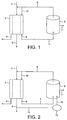
- Fig. 1 there is shown a schematic representation of apparatus according to the invention.
- An aqueous ion containing solution containing fluoride and ammonium ions is admitted into an ion adsorption unit 3 (ERIX unit) forming part of a closed loop circulation system 1, via line 2.
- ERIX unit 3 an example of which is described in detail by reference to Fig. 4 of the drawings
- the aqueous solution is treated and separated to form a concentrated ammonium solution which is discharged through line 4, a concentrated fluoride solution which is discharged through line 6 and a depleted aqueous solution which is discharged through line 5.
- the line 6 containing the concentrated fluoride solution forms part of the closed loop circulation system 1 and leads to a circulation pump (not shown) for maintaining circulating flow within the loop.
- a separate line may be provided for make-up water, if required, although such make-up water can be admitted at almost any part of the loop system 1.
- precipitation unit 9 Downstream of the pump there is a precipitation unit 9 containing a suitable source of calcium (preferably in soluble form) which reacts with the fluoride solution to form insoluble CaF 2 .
- a precipitation unit 9 containing a suitable source of calcium (preferably in soluble form) which reacts with the fluoride solution to form insoluble CaF 2 .
- Such precipitation units are well known to those skilled in the art and do not require detailed description here.
- Precipitated CaF 2 is removed through line 7.
- the eluate from the precipitation unit 9 contains only 20 to 30 ppm F and passes by way of line 8 to the line 2 through which fresh fluoride/ammonium solution enters the system. If desired, some of the fluoride containing eluate in line 8 may be admitted to the fluoride concentrate side of the ERIX unit 3 via line 10.
- FIG. 2 A modified and preferred form of apparatus is represented schematically in Fig. 2 . That apparatus is similar in most respects to that shown in Fig. 1 except that some of the water exiting the ERIX unit through line 5 is taken via a bleed line 11 to a mixing tank 12 where it is used to form the source of calcium as solution or slurry. That in turn is passed through line 13 to the precipitation unit 9. In this manner, the water balance of the system is more easily controlled and maintained.
- FIG. 3 A still further modification of the apparatus is shown in Fig. 3 .
- the calcium hydroxide is slurried not with water exiting the ERIX unit via line 5 but with recycled water from the calcium fluoride precipitation unit taken from line 8 through line 14.
- this arrangement reduces the burden on the ERIX unit by reducing significantly the quantity of aqueous fluoride recycled through the ERIX unit.
- the recycled aqueous fluoride can be cycled entirely past the back surface of the ion exchange material in the ERIX unit so that it is not subjected to the ion exchange process.
- FIG. 4 of the drawings there is shown an example of an electrochemical cell suitable for incorporation into the closed loop circulation systems shown in Figs. 1 to 3 .
- the electrochemical cell 30 shown in Fig. 4 comprises an electrode assembly 11 and an electrode assembly 31 spaced apart by a dividing section 32 which incorporates an inlet port 33 and an outlet port 35 for aqueous solution.
- the electrode assemblies 11 and 31 and dividing section 32 together define a solution compartment 37.
- the electrode assemblies are separated from the solution compartment by suitable ion permeable membranes, 12 and 13, that allow cations to move into a cathode compartment 34 and anions to move into an anode compartment 14.
- the anode compartment 14 contains an anode 20 and the cathode compartment 34 contains a cathode 39.
- Catholyte solution can be introduced and removed from the cathode compartment 34 through ports 15 and 16 and anolyte solution can be introduced and removed from the anode compartment 14 through ports 18 and 19.
- the solution compartment 37 is filled with suitable ion exchange material for the anions and cations to be adsorbed.
- the aqueous solution of fluoride and ammonium ions passes continuously through the compartment 37 via inlet 33 and outlet 35 and within the cell the ions are adsorbed onto the resin.
- An electrical potential between the electrodes 20 and 39 causes fluoride ions to be adsorbed on and to pass through the ion exchange layer to membrane 12 and through that membrane into the anode compartment 14, and ammonium ions to be adsorbed on and to pass through the ion exchange layer to membrane 13 and through that membrane into the cathode compartment 34, generating concentrated fluoride and ammonium solutions in the anode and cathode compartments, respectively.
- Aqueous solution depleted in fluoride ions and ammonium ions flows out of the cell through outlet port 35.
- a waste water feed of 10,000 litres per hour containing 500 ppm fluoride was passed into the ERIX unit which achieved a fluoride removal efficiency of 100%, i.e. the treated water exiting the ERIX unit was free of fluoride ions.
- 6,300 litres per hour of 1500 ppm calcium hydroxide liquor was passed to the precipitation unit which achieved 100% removal of precipitated solids.
- 6,300 litres per hour of fluoride containing liquor from the precipitation unit was recycled to the ERIX unit.
Landscapes
- Chemical & Material Sciences (AREA)
- Engineering & Computer Science (AREA)
- Analytical Chemistry (AREA)
- General Chemical & Material Sciences (AREA)
- Oil, Petroleum & Natural Gas (AREA)
- Chemical Kinetics & Catalysis (AREA)
- Environmental & Geological Engineering (AREA)
- Hydrology & Water Resources (AREA)
- Life Sciences & Earth Sciences (AREA)
- Water Supply & Treatment (AREA)
- Organic Chemistry (AREA)
- Water Treatment By Electricity Or Magnetism (AREA)
- Removal Of Specific Substances (AREA)
- Treatment Of Water By Ion Exchange (AREA)
- Separation Using Semi-Permeable Membranes (AREA)
- Water Treatment By Sorption (AREA)
Description
- This invention relates to the treatment of toxic and/or environmentally hazardous or harmful materials and more especially to the treatment of aqueous solutions of hazardous waste arising from various chemical processes.
- The chemical processing industry in general generates vast quantities of by-products and waste materials many of which represent environmental hazards and which must be neutralised or destroyed as an essential part of their ultimate disposal. The oil and gas processing industries, for example, invest heavily in plant and equipment designed specifically to prevent or minimise the release of harmful largely organic materials into the environment. The microelectronics and semi-conductor device manufacturing industries, for example, make similar investments in order to scrub or otherwise treat exhaust gas streams containing generally inorganic materials from chemical processing units prior to the release of those exhaust gases into the atmosphere. Compounds containing heavy metals and halogen-, sulphur-, phosphorus- and nitrogen-containing compounds can be especially toxic and their removal is the subject of a considerable amount of technical research and of much environmental protection legislation.
- Many of the procedures utilised in the microelectronics and semi-conductor device manufacturing industries use fluorine-containing compounds. Unused fluorine-containing compounds and fluorine-containing products and by-products are generally discharged from the process or from a subsequent exhaust treatment, for example scrubbers and other adsorption systems, as an aqueous waste stream. This aqueous waste stream will generally contain fluorine in the form of HF. However, cationic species such as NH4 + may also be present, in addition to fluoride in the form of bifluoride ions, HF2 -.
- Current practise in such manufacturing and disposal facilities involves treating the aqueous fluoride stream with magnesium or calcium salts in order to precipitate the sparingly soluble MgF2 and CaF2, usually the latter. The solid material can then be compacted and dried for ease of transport for disposal or further use. However, the water stream will still have a fluoride content of some 20 to 30 ppm which continues to present a disposal problem with discharge limits of 3 ppm being more generally imposed.
- Further, some legislative areas prohibit the dilution of certain waste streams (for example, aqueous fluoride with an aqueous stream containing no fluoride) for disposal purposes and in other areas allowable discharge is based on the quantity of discharged species and not their concentrations. The safe disposal of hazardous and harmful materials therefore presents ever increasing problems.
- A further difficulty is that effluent from recently developed procedures which use a mixture of ammonium bifluoride and HF cannot be accommodated in a calcium precipitation installation because CaF2 will not form at pH below 12 and such high pH values favour the dissociation of ammonium species to produce ammonia gas. Additional facilities are then required to remove and separate NH4 + and F before they can be treated to form solid waste. This can be achieved using traditional ion exchange techniques but the plant will be large in that it will require separate beds for the two ion exchange species and duplex systems with further chemical feeds for their periodic regeneration.
- A recently developed system that is capable of removing both anionic and cationic species from aqueous solutions without requiring further chemical additives makes use of a technique known as electrochemical deionisation which involves ion exchange and electrolytic separation technologies. In this system cations or anions of interest are adsorbed from dilute aqueous solution onto an ion exchange medium, transported through that medium by an applied electric field and continuously eluted as a concentrated stream. Such a procedure is described in
EP 0680932B . There are many examples within the existing literature of electrochemical cells that combine adsorption and ion separation andEP 0680932B illustrates one such ion removal/separation/concentration process. Other approaches will be known to those skilled in the art and can also be used. Such systems have been applied with some success on a continuous basis to minimise water consumption and to concentrate anions or cations for ease of subsequent handling in our copending Patent Application No.GB 0300793.7 - Further work has now revealed that the techniques and procedures described in
GB 0300793.7 GB 0300793.7 - In accordance with the invention, there is now provided a method for the treatment of aqueous streams containing both anionic and cationic species, the method comprising the steps of:
- continuously circulating water through an essentially closed loop incorporating an ion adsorption unit comprising a water permeable layer of an ion adsorbing material;
- feeding to the essentially closed loop an aqueous solution containing the anionic and the cationic species;
- continuously passing the circulating water including the aqueous solution containing the an ionic and the cationic species through the ion adsorbing material in the ion adsorption unit while applying an electric potential across the thickness of the layer of ion adsorbing material and removing from the ion adsorption unit more concentrated aqueous solutions of the separate ionic species;
- continuously discharging from the ion adsorption unit the more concentrated aqueous solution of one ionic species;
- continuously discharging from the ion adsorption unit the aqueous solution depleted in anionic and cationic species;
- continuously passing the more concentrated solution of the other ionic species through a reaction unit in which the ionic species reacts to form a water-insoluble solid material;
- continuously recycling the eluate from the reaction unit to the ion adsorption unit; and, if necessary,
- adding to the closed loop a quantity of water corresponding the quantity of aqueous solution removed from the closed loop with the solids in the reaction unit.
- In a separate aspect, the invention provides also apparatus for use in carrying out the method described above, the apparatus comprising:
- an essentially closed loop circulation system containing (i) an ion adsorption unit comprising a water permeable zone of an ion adsorbing material and means for enabling an electrical potential to be applied across the thickness of the ion adsorbing zone and (ii) a reaction unit in which one of the anionic and cationic species is rendered substantially insoluble;
- a pump for continuously circulating aqueous solution around the closed loop;
- an inlet for an aqueous solution containing anionic and cationic species to the closed loop circulation system;
- an outlet for concentrated aqueous solution of one ionic species from the ion adsorption unit;
- an outlet for concentrated aqueous solution of the other ionic species from the ion adsorption unit;
- an outlet for depleted aqueous solution from the ion adsorption unit;
- an outlet for solid from the reaction unit; and
- an inlet for water into the closed loop circulation system.
- The ion adsorption unit employed as an essential aspect of the method and apparatus of the invention preferably incorporates both anion adsorbing and cation adsorbing capabilities in the unit. However, if necessary or desirable, it may be advantageous to use two separate ion adsorption units disposed in series one for anion adsorption and the other for cation adsorption. Still further, an ion adsorption unit having both anion adsorbing and cation adsorbing capabilities may be supplemented by a series-connected ion adsorption unit having only an anion adsorbing or a cation adsorbing capability. The precise arrangement will depend upon the relative concentrations of the anionic and cationic species in the aqueous solution fed to the ion adsorption units, the efficiency of the ion adsorption units in removing anions and/or cations of interest from the aqueous solution and the residual concentrations of the anions and the cations in the depleted aqueous solution having regard to any further treatment to which that solution may be subjected. In general terms, however, the skilled person will have no special difficulty in selecting the most appropriate combination of ion adsorption units and ion adsorbing materials for the particular situation and circumstances.
- The ion adsorbing materials serve to capture the ions of interest and are preferably ion exchange materials such as ion exchange resins in the form of particles or beads or other materials that can provide:
- a solution permeable medium;
- an ion adsorption medium (to remove the anions or cations);
- an ion conducting medium whereby the ions may be moved by the imposed electrical field into a separate solution.
- The particles or beads of the resins are preferably in a coherent form, that is to say they are not mobile or loose but are constrained in a predetermined configuration. For example, the particles of beads may be bound together with a binder or held between layers of a mesh or membrane so as to be permeable to the aqueous solution containing the ions, the mesh or membrane being permeable as appropriate for the removal and concentration of the ions of interest. The electrical potential which is applied across the thickness of the layer of ion adsorbing material serves to drive the captured ions through the ion adsorbing material towards one or other of the electrodes through which the potential is applied. The electrical potential may be generated from a pair of electrodes arranged to form an electrolysis cell or by any alternative arrangement, for example in the form of an electrophoresis cell.
- It will be understood that the ion adsorption unit consisting of ion exchange material is, in operation, self-regenerating in that it effectively transports the captured cations and/or anions through its bulk for discharge as a concentrated aqueous solution, and will regenerate to its hydrogen or hydroxide form when no other cationic or anionic species is present. Such an electrically regenerating ion exchange unit is referred to hereinafter as an ERIX unit for the sake of brevity. Such units may comprise many ion removal and concentration channels in parallel and will be known to those skilled in the art.
- It has been found that using the method and apparatus according to the invention it is possible to effect continuous separation of anions and cations with a closed loop circulation system without any need for regenerating or periodically replacing the ion adsorbing materials. The efficiency of the method and apparatus will depend upon the nature of the ion adsorbing materials and of the ions to be captured, the concentration of the ions in the solution and other factors such as flow rates and electrical potentials but initial indications are that ion extraction rates of up to 98% per pass can be achieved.
- With such high extraction rates, the removal of acid anions such as F- as well as SO4 2- and NO3 - will have a dramatic effect upon improving the service life of the equipment in the circulating system, such as pumps, meters, valves and baffles.
- The method of the invention is applicable to a wide variety of anionic species such as sulphate, sulphite, nitrate, nitrite, phosphate, phosphite and halides, that is to say fluoride, chloride, bromide and iodide as well as cationic species especially metals and more especially heavy metals.
- The invention does, however, have particular applicability to fluoride such as that generated as a by-product of the semi-conductor device manufacturing industry and which produces aqueous hydrofluoric acid as a result of reaction followed by dissolution in a gas scrubbing plant. The invention is most especially useful for aqueous solutions containing both fluoride and ammonium ions which have been difficult to separate in a satisfactory manner by more traditional techniques, as described above.
- In its preferred aspect, therefore, the invention permits the separation of ammonium and fluoride ions from aqueous solution using an electrically regenerating ion exchange (ERIX) system. By incorporating the ERIX unit into a recirculation loop, the concentrated fluoride solution can be passed through a calcium precipitation unit thereby capturing fluoride in solid form. The eluate from the precipitation unit can then be recycled to the ERIX unit in combination with additional waste water feed.
- In this manner, fluoride is safely and efficiently removed from the waste water as solid CaF2, ammonium ions are separated and discharged and purified water is obtained.
- In an especially preferred method, the amount of calcium admitted to the precipitation unit is significantly less than that required by stoichiometric considerations for capturing all of the fluoride ions in the concentrated stream discharged from the ERIX unit. In this way, the fluoride ion concentration in the effluent from the precipitation unit can be maintained at a level such that the concentration of calcium in that effluent is extremely low. This in turn helps to safeguard the ERIX unit which could rapidly become clogged, or at least severely contaminated, by solid calcium deposits derived from soluble calcium in the effluent.
- The calcium that is fed to the precipitation unit for the formation of CaF2 is preferably in soluble form but simple economic considerations may demand the use of calcium in an insoluble or sparingly soluble form. For example, calcium hydroxide slurries and calcium carbonate slurries may be used with advantage. However, a considerable quantity of water will be required to form such slurries and it may therefore be advantageous to use at least some of the treated water exiting the ERIX unit for this purpose. In this manner there is little or no necessity to introduce fresh water into the loop.
- In an alternative arrangement, fluoride-containing eluent from the precipitation unit may be recycled for the purpose of forming the calcium slurry. This alternative has the advantage of consuming some of the fluoride exiting the precipitation unit and thereby reducing the fluoride burden on the ERIX unit.
- The invention is described below in greater detail by way of example only with reference to the accompanying drawings, in which:
-
Fig. 1 is a schematic representation of a closed loop circulation treatment apparatus according to the invention; -
Fig. 2 is a schematic representation of a preferred form of closed loop circulation treatment apparatus according to the invention; -
Fig. 3 is a schematic representation of a further form of closed loop circulation treatment apparatus according to the invention; and -
Fig. 4 is a schematic representation of an example of an electrochemical cell which may be used in the apparatus shown inFigs. 1,2 and3 . - Referring to the drawings, in
Fig. 1 there is shown a schematic representation of apparatus according to the invention. An aqueous ion containing solution containing fluoride and ammonium ions is admitted into an ion adsorption unit 3 (ERIX unit) forming part of a closedloop circulation system 1, vialine 2. Within the ERIX unit 3 (an example of which is described in detail by reference toFig. 4 of the drawings) the aqueous solution is treated and separated to form a concentrated ammonium solution which is discharged throughline 4, a concentrated fluoride solution which is discharged throughline 6 and a depleted aqueous solution which is discharged throughline 5. - The
line 6 containing the concentrated fluoride solution forms part of the closedloop circulation system 1 and leads to a circulation pump (not shown) for maintaining circulating flow within the loop. A separate line may be provided for make-up water, if required, although such make-up water can be admitted at almost any part of theloop system 1. - Downstream of the pump there is a
precipitation unit 9 containing a suitable source of calcium (preferably in soluble form) which reacts with the fluoride solution to form insoluble CaF2. Such precipitation units are well known to those skilled in the art and do not require detailed description here. Precipitated CaF2 is removed throughline 7. - The eluate from the
precipitation unit 9 contains only 20 to 30 ppm F and passes by way ofline 8 to theline 2 through which fresh fluoride/ammonium solution enters the system. If desired, some of the fluoride containing eluate inline 8 may be admitted to the fluoride concentrate side of theERIX unit 3 vialine 10. - A modified and preferred form of apparatus is represented schematically in
Fig. 2 . That apparatus is similar in most respects to that shown inFig. 1 except that some of the water exiting the ERIX unit throughline 5 is taken via ableed line 11 to amixing tank 12 where it is used to form the source of calcium as solution or slurry. That in turn is passed throughline 13 to theprecipitation unit 9. In this manner, the water balance of the system is more easily controlled and maintained. - A still further modification of the apparatus is shown in
Fig. 3 . In this case, however, the calcium hydroxide is slurried not with water exiting the ERIX unit vialine 5 but with recycled water from the calcium fluoride precipitation unit taken fromline 8 throughline 14. As noted above, this arrangement reduces the burden on the ERIX unit by reducing significantly the quantity of aqueous fluoride recycled through the ERIX unit. In fact, as shown inFig. 3 , the recycled aqueous fluoride can be cycled entirely past the back surface of the ion exchange material in the ERIX unit so that it is not subjected to the ion exchange process. - Turning now to
Fig. 4 of the drawings, there is shown an example of an electrochemical cell suitable for incorporation into the closed loop circulation systems shown inFigs. 1 to 3 . - The
electrochemical cell 30 shown inFig. 4 comprises anelectrode assembly 11 and anelectrode assembly 31 spaced apart by a dividingsection 32 which incorporates aninlet port 33 and anoutlet port 35 for aqueous solution. Theelectrode assemblies section 32 together define asolution compartment 37. - The electrode assemblies are separated from the solution compartment by suitable ion permeable membranes, 12 and 13, that allow cations to move into a
cathode compartment 34 and anions to move into ananode compartment 14. Theanode compartment 14 contains ananode 20 and thecathode compartment 34 contains acathode 39. - Catholyte solution can be introduced and removed from the
cathode compartment 34 throughports anode compartment 14 throughports solution compartment 37 is filled with suitable ion exchange material for the anions and cations to be adsorbed. - The aqueous solution of fluoride and ammonium ions passes continuously through the
compartment 37 viainlet 33 andoutlet 35 and within the cell the ions are adsorbed onto the resin. An electrical potential between theelectrodes membrane 12 and through that membrane into theanode compartment 14, and ammonium ions to be adsorbed on and to pass through the ion exchange layer tomembrane 13 and through that membrane into thecathode compartment 34, generating concentrated fluoride and ammonium solutions in the anode and cathode compartments, respectively. Aqueous solution depleted in fluoride ions and ammonium ions flows out of the cell throughoutlet port 35. - In an example of the method of the invention, carried out using apparatus as shown in
Fig. 2 of the drawings, a waste water feed of 10,000 litres per hour containing 500 ppm fluoride was passed into the ERIX unit which achieved a fluoride removal efficiency of 100%, i.e. the treated water exiting the ERIX unit was free of fluoride ions. 6,300 litres per hour of 1500 ppm calcium hydroxide liquor was passed to the precipitation unit which achieved 100% removal of precipitated solids. 6,300 litres per hour of fluoride containing liquor from the precipitation unit was recycled to the ERIX unit.
Claims (14)
- A method for the treatment of an aqueous stream containing both anionic and cationic species, the method comprising the steps of:continuously circulating water through an essentially closed loop incorporating an ion adsorption unit comprising a water permeable layer of an ion adsorbing material;feeding to the essentially closed loop an aqueous solution containing the anionic and the cationic species;continuously passing the circulating water including the aqueous solution containing the ionic and the cationic species through the ion adsorbing material in the ion adsorption unit while applying an electric potential across the thickness of the layer of ion adsorbing material and removing from the ion adsorption unit more concentrated aqueous solutions of the separate ionic species;continuously discharging from the ion adsorption unit the more concentrated aqueous solution of one ionic species;continuously discharging from the ion adsorption unit the aqueous solution depleted in anionic and cationic species;continuously passing the more concentrated solution of the other ionic species through a reaction unit in which the ionic species reacts to form a water-insoluble solid material;continuously recycling eluate from the reaction unit to the ion adsorption unit; and, if necessary,adding to the closed loop a quantity of water corresponding the quantity of aqueous solution removed from the reaction unit.
- A method according to claim 1, wherein the anionic species is fluoride and the cationic species is ammonium.
- A method according to claim 2, wherein a concentrated aqueous ammonium solution is continuously discharged from the ion adsorption unit.
- A method according to claim 2 or claim 3, wherein a concentrated aqueous fluoride solution is continuously passed from the ion adsorption unit into a calcium precipitation unit thereby to form CaF2.
- A method according to claim 4, wherein a source of calcium as a solution or slurry is continuously admitted to the calcium precipitation unit.
- A method according to claim 5, wherein the source of calcium is a slurry of calcium carbonate or of calcium hydroxide.
- A method according to claim 5 or claim 6, wherein depleted aqueous solution continuously discharged from the ion adsorption unit is used to prepare the solution or slurry of calcium.
- A method according to claim 5 or claim 6, wherein eluate from the calcium precipitation unit is used to prepare the solution or slurry of calcium.
- A method according to any one of claims 4 to 8, wherein the amount of calcium admitted to the calcium precipitation unit is less than the stoichiometric amount for capturing fluoride and wherein the fluoride containing eluate from the precipitation unit is recycled to the ion adsorption unit to combine with the concentrated fluoride solution.
- Apparatus for use in carrying out the method of claim 1, the apparatus comprising:an essentially closed loop circulation system containing (i) an ion adsorption unit (3) comprising a water permeable zone of an ion adsorbing material and means for enabling an electrical potential to be applied across the thickness of that zone and (ii) a reaction unit (9) in which one of the anionic and cationic species is rendered substantially insoluble;a pump for continuously circulating aqueous solution around the closed loop;an inlet (2) for an aqueous solution containing anionic and cationic species to the closed loop circulation system;an outlet (4) for concentrated aqueous solution of one ionic species from the ion adsorption unit;an outlet (6) for concentrated aqueous solution of the other ionic species from the ion adsorption unit;an outlet (5) for depleted aqueous solution from the ion adsorption unit;an outlet (7) for solid from the reaction unit; andan inlet for water into the closed loop circulation system.
- Apparatus according to claim 10, wherein the reaction unit (9) is a calcium fluoride precipitation unit which comprises an inlet for an aqueous solution or slurry of a calcium source, an inlet for concentrated aqueous fluoride solution, an outlet for calcium fluoride and an outlet for aqueous fluoride eluate.
- Apparatus according to claim 11, wherein the inlet for the aqueous solution or slurry of the calcium source is operatively connected to a mixing vessel (12) in which the calcium source is mixed with water.
- Apparatus according to claim 12, wherein the mixing vessel (12) is operatively connected to the outlet for depleted aqueous solution from the ion adsorption unit.
- Apparatus according to claim 12, wherein the mixing vessel (12) is operatively connected to the outlet for aqueous fluoride eluate from the calcium fluoride precipitation unit.
Applications Claiming Priority (2)
| Application Number | Priority Date | Filing Date | Title |
|---|---|---|---|
| GBGB0321579.5A GB0321579D0 (en) | 2003-09-15 | 2003-09-15 | Treatment of aqueous chemical waste |
| PCT/GB2004/003876 WO2005026055A2 (en) | 2003-09-15 | 2004-09-10 | Treatment of aqueous chemical waste |
Publications (2)
| Publication Number | Publication Date |
|---|---|
| EP1663872A2 EP1663872A2 (en) | 2006-06-07 |
| EP1663872B1 true EP1663872B1 (en) | 2016-04-27 |
Family
ID=29227112
Family Applications (1)
| Application Number | Title | Priority Date | Filing Date |
|---|---|---|---|
| EP04768423.8A Expired - Lifetime EP1663872B1 (en) | 2003-09-15 | 2004-09-10 | Treatment of aqueous chemical waste |
Country Status (8)
| Country | Link |
|---|---|
| US (1) | US8246804B2 (en) |
| EP (1) | EP1663872B1 (en) |
| JP (1) | JP4481987B2 (en) |
| KR (1) | KR101107889B1 (en) |
| CN (1) | CN100408489C (en) |
| GB (1) | GB0321579D0 (en) |
| TW (1) | TWI356045B (en) |
| WO (1) | WO2005026055A2 (en) |
Families Citing this family (4)
| Publication number | Priority date | Publication date | Assignee | Title |
|---|---|---|---|---|
| US7514004B1 (en) * | 2008-05-01 | 2009-04-07 | Sandia Corporation | In-tank recirculating arsenic treatment system |
| JP5114441B2 (en) * | 2009-02-23 | 2013-01-09 | オルガノ株式会社 | Desalination chamber container, electrode chamber cap, and electrical deionized water production device |
| TWI602784B (en) * | 2012-05-28 | 2017-10-21 | 黃武章 | A regeneration method for high-hardness wastewater containing heavy metal |
| CN115893703A (en) * | 2022-10-08 | 2023-04-04 | 同济大学 | Photovoltaic-driven automatic defluorination device and method for high-fluorine underground water |
Family Cites Families (26)
| Publication number | Priority date | Publication date | Assignee | Title |
|---|---|---|---|---|
| US3607694A (en) * | 1968-04-08 | 1971-09-21 | Sybron Corp | Per(halo-oxygen) acid oxidation,purification and recovery process |
| WO1983003984A1 (en) * | 1982-05-13 | 1983-11-24 | Gerhard Kunz | Method for the treatment of a liquid phase, particularly method for desalting aqueous solutions, as well as device for its implementation |
| US4599156A (en) * | 1985-09-27 | 1986-07-08 | International Minerals & Chemical Corp. | Electrodialysis process for preparing hydrogen fluoride |
| US4871431A (en) * | 1988-07-11 | 1989-10-03 | Ionics, Incorporated | Apparatus for the removal of dissolved solids from liquids using bipolar membranes |
| US4969983A (en) * | 1988-07-11 | 1990-11-13 | Ionics, Incorporated | Apparatus and process for the removal of acidic and basic gases from fluid mixtures using bipolar membranes |
| GB9002244D0 (en) * | 1990-02-01 | 1990-03-28 | Atomic Energy Authority Uk | Separation method |
| US5215632A (en) * | 1990-04-30 | 1993-06-01 | Occidental Chemical Corporation | Fluoride removal from aqueous streams |
| JP3378892B2 (en) * | 1991-10-03 | 2003-02-17 | ステラケミファ株式会社 | Method for recovering calcium fluoride from fluorine-based etchant |
| US5403495A (en) * | 1992-03-13 | 1995-04-04 | Tetra Technologies, Inc. | Fluoride removal system |
| SE9303766L (en) * | 1993-11-15 | 1995-05-16 | Eka Nobel Ab | Procedure for purification and recirculation of solutions |
| US5413682A (en) * | 1994-03-28 | 1995-05-09 | General Electric Company | Recovery of fluoride from waste solutions |
| EP0680932B1 (en) * | 1994-05-06 | 2001-08-08 | AEA Technology plc | Electrochemical deionisation |
| US5584981A (en) | 1994-05-06 | 1996-12-17 | United Kingdom Atomic Energy Authority | Electrochemical deionization |
| JPH09262588A (en) * | 1996-03-29 | 1997-10-07 | Toshiba Corp | Fluorine recovery method and wastewater treatment method |
| US6074537A (en) * | 1996-04-29 | 2000-06-13 | Compliance Consultants, Inc. | Equipment for electochemical collection removal of ions |
| JP2000296314A (en) * | 1999-04-12 | 2000-10-24 | Kurita Water Ind Ltd | Electrodesalting method and apparatus |
| JP2001026418A (en) * | 1999-07-16 | 2001-01-30 | Taiheiyo Cement Corp | Method for recovering industrially useful inorganic material and industrially useful inorganic material recovered by the recovery method |
| US6379518B1 (en) | 1999-08-11 | 2002-04-30 | Kurita Water Industries Ltd. | Electrodeionization apparatus and pure water producing apparatus |
| US6274019B1 (en) | 2000-03-08 | 2001-08-14 | Organo Corporation | Electrodeionization apparatus |
| US6613230B2 (en) * | 2000-07-07 | 2003-09-02 | Ionics, Incorporated | Method for simultaneous removal of arsenic and fluoride from aqueous solutions |
| JP3951642B2 (en) * | 2000-07-13 | 2007-08-01 | 栗田工業株式会社 | Method for operating electrodeionization apparatus, electrodeionization apparatus and electrodeionization system |
| US6652758B2 (en) * | 2000-09-26 | 2003-11-25 | Ionics, Incorporated | Simultaneous ammonia and fluoride treatment for wastewater |
| JP2003039081A (en) * | 2001-07-30 | 2003-02-12 | Hitachi Ltd | Phosphorus recovery equipment |
| JP3773178B2 (en) * | 2001-12-07 | 2006-05-10 | オルガノ株式会社 | Electric deionized water production apparatus and production method |
| US6905608B2 (en) | 2002-01-22 | 2005-06-14 | Exergy Technologies Corporation | Advanced electrodeionization for fluid recycling |
| KR20050092407A (en) * | 2003-01-14 | 2005-09-21 | 더 비오씨 그룹 피엘씨 | Treatment of chemical waste |
-
2003
- 2003-09-15 GB GBGB0321579.5A patent/GB0321579D0/en not_active Ceased
-
2004
- 2004-09-10 WO PCT/GB2004/003876 patent/WO2005026055A2/en not_active Ceased
- 2004-09-10 JP JP2006526677A patent/JP4481987B2/en not_active Expired - Lifetime
- 2004-09-10 KR KR1020067005170A patent/KR101107889B1/en not_active Expired - Fee Related
- 2004-09-10 EP EP04768423.8A patent/EP1663872B1/en not_active Expired - Lifetime
- 2004-09-10 CN CNB2004800266419A patent/CN100408489C/en not_active Expired - Fee Related
- 2004-09-10 US US10/572,187 patent/US8246804B2/en not_active Expired - Fee Related
- 2004-09-15 TW TW093127802A patent/TWI356045B/en not_active IP Right Cessation
Also Published As
| Publication number | Publication date |
|---|---|
| EP1663872A2 (en) | 2006-06-07 |
| TWI356045B (en) | 2012-01-11 |
| KR20060080929A (en) | 2006-07-11 |
| TW200514752A (en) | 2005-05-01 |
| GB0321579D0 (en) | 2003-10-15 |
| US20070246429A1 (en) | 2007-10-25 |
| KR101107889B1 (en) | 2012-01-25 |
| CN1852866A (en) | 2006-10-25 |
| US8246804B2 (en) | 2012-08-21 |
| CN100408489C (en) | 2008-08-06 |
| JP4481987B2 (en) | 2010-06-16 |
| JP2007505732A (en) | 2007-03-15 |
| WO2005026055A3 (en) | 2005-06-30 |
| WO2005026055A2 (en) | 2005-03-24 |
Similar Documents
| Publication | Publication Date | Title |
|---|---|---|
| EP2867388B1 (en) | Process and apparatus for generating or recovering hydrochloric acid from metal salt solutions | |
| US20120318743A1 (en) | Water Desalination and Treatment System and Method | |
| CA2148876A1 (en) | Ion exchange resin regeneration apparatus | |
| US5804057A (en) | Method of removing metal salts from solution by electrolysis an electrode closely associated with an ion exchange resin | |
| EP2949630A1 (en) | Water recovery device for closed system space | |
| US20100133115A1 (en) | Devices and methods for acid and base generation | |
| WO1993002227A1 (en) | Process and apparatus for treating fluoride containing acid solutions | |
| US4636288A (en) | Electrodialytic conversion of multivalent metal salts | |
| AU2004314343B2 (en) | Electrochemical nitrate destruction | |
| US8246804B2 (en) | Treatment of aqueous chemical waste | |
| KR101154154B1 (en) | Electromembrane process and apparatus | |
| EP1480913B9 (en) | Nitrate removal | |
| CN101193823A (en) | Electrodialysis device, wastewater treatment method and fluorine treatment system | |
| US20060101995A1 (en) | Treatment of chemical waste | |
| CN112437754A (en) | Method for removing contaminants from wastewater from an industrial plant and system for implementing such a method | |
| GB2403166A (en) | Electrodeionisation process | |
| US7887707B2 (en) | Regeneration of water treatment substrates | |
| CN1329319C (en) | Method and device for treating gaseous chemical waste | |
| Povorov et al. | Hydrofluoric acid recovery integrated membrane technology from glass production concentrated washing waters | |
| Curtis et al. | Pollution abatement: A metal recovery technique for treating electroplating effluents. |
Legal Events
| Date | Code | Title | Description |
|---|---|---|---|
| PUAI | Public reference made under article 153(3) epc to a published international application that has entered the european phase |
Free format text: ORIGINAL CODE: 0009012 |
|
| 17P | Request for examination filed |
Effective date: 20060210 |
|
| AK | Designated contracting states |
Kind code of ref document: A2 Designated state(s): AT BE BG CH CY CZ DE DK EE ES FI FR GB GR HU IE IT LI LU MC NL PL PT RO SE SI SK TR |
|
| DAX | Request for extension of the european patent (deleted) | ||
| RAP1 | Party data changed (applicant data changed or rights of an application transferred) |
Owner name: EDWARDS LIMITED |
|
| 17Q | First examination report despatched |
Effective date: 20120521 |
|
| GRAP | Despatch of communication of intention to grant a patent |
Free format text: ORIGINAL CODE: EPIDOSNIGR1 |
|
| INTG | Intention to grant announced |
Effective date: 20151210 |
|
| RIN1 | Information on inventor provided before grant (corrected) |
Inventor name: JONES, CHRISTOPHER, PETER Inventor name: MAWLE, PETER JAMES |
|
| GRAS | Grant fee paid |
Free format text: ORIGINAL CODE: EPIDOSNIGR3 |
|
| GRAA | (expected) grant |
Free format text: ORIGINAL CODE: 0009210 |
|
| AK | Designated contracting states |
Kind code of ref document: B1 Designated state(s): AT BE BG CH CY CZ DE DK EE ES FI FR GB GR HU IE IT LI LU MC NL PL PT RO SE SI SK TR |
|
| REG | Reference to a national code |
Ref country code: GB Ref legal event code: FG4D |
|
| REG | Reference to a national code |
Ref country code: CH Ref legal event code: EP Ref country code: DE Ref legal event code: R081 Ref document number: 602004049192 Country of ref document: DE Owner name: EDWARDS LTD., BURGESS HILL, GB Free format text: FORMER OWNER: THE BOC GROUP PLC, WINDLESHAM, SURREY, GB |
|
| REG | Reference to a national code |
Ref country code: AT Ref legal event code: REF Ref document number: 794588 Country of ref document: AT Kind code of ref document: T Effective date: 20160515 |
|
| REG | Reference to a national code |
Ref country code: IE Ref legal event code: FG4D |
|
| REG | Reference to a national code |
Ref country code: DE Ref legal event code: R096 Ref document number: 602004049192 Country of ref document: DE |
|
| REG | Reference to a national code |
Ref country code: NL Ref legal event code: MP Effective date: 20160427 |
|
| REG | Reference to a national code |
Ref country code: AT Ref legal event code: MK05 Ref document number: 794588 Country of ref document: AT Kind code of ref document: T Effective date: 20160427 |
|
| REG | Reference to a national code |
Ref country code: FR Ref legal event code: PLFP Year of fee payment: 13 |
|
| PG25 | Lapsed in a contracting state [announced via postgrant information from national office to epo] |
Ref country code: NL Free format text: LAPSE BECAUSE OF FAILURE TO SUBMIT A TRANSLATION OF THE DESCRIPTION OR TO PAY THE FEE WITHIN THE PRESCRIBED TIME-LIMIT Effective date: 20160427 |
|
| PG25 | Lapsed in a contracting state [announced via postgrant information from national office to epo] |
Ref country code: PL Free format text: LAPSE BECAUSE OF FAILURE TO SUBMIT A TRANSLATION OF THE DESCRIPTION OR TO PAY THE FEE WITHIN THE PRESCRIBED TIME-LIMIT Effective date: 20160427 Ref country code: FI Free format text: LAPSE BECAUSE OF FAILURE TO SUBMIT A TRANSLATION OF THE DESCRIPTION OR TO PAY THE FEE WITHIN THE PRESCRIBED TIME-LIMIT Effective date: 20160427 |
|
| PG25 | Lapsed in a contracting state [announced via postgrant information from national office to epo] |
Ref country code: SE Free format text: LAPSE BECAUSE OF FAILURE TO SUBMIT A TRANSLATION OF THE DESCRIPTION OR TO PAY THE FEE WITHIN THE PRESCRIBED TIME-LIMIT Effective date: 20160427 Ref country code: AT Free format text: LAPSE BECAUSE OF FAILURE TO SUBMIT A TRANSLATION OF THE DESCRIPTION OR TO PAY THE FEE WITHIN THE PRESCRIBED TIME-LIMIT Effective date: 20160427 Ref country code: PT Free format text: LAPSE BECAUSE OF FAILURE TO SUBMIT A TRANSLATION OF THE DESCRIPTION OR TO PAY THE FEE WITHIN THE PRESCRIBED TIME-LIMIT Effective date: 20160829 Ref country code: ES Free format text: LAPSE BECAUSE OF FAILURE TO SUBMIT A TRANSLATION OF THE DESCRIPTION OR TO PAY THE FEE WITHIN THE PRESCRIBED TIME-LIMIT Effective date: 20160427 Ref country code: GR Free format text: LAPSE BECAUSE OF FAILURE TO SUBMIT A TRANSLATION OF THE DESCRIPTION OR TO PAY THE FEE WITHIN THE PRESCRIBED TIME-LIMIT Effective date: 20160728 |
|
| PG25 | Lapsed in a contracting state [announced via postgrant information from national office to epo] |
Ref country code: BE Free format text: LAPSE BECAUSE OF FAILURE TO SUBMIT A TRANSLATION OF THE DESCRIPTION OR TO PAY THE FEE WITHIN THE PRESCRIBED TIME-LIMIT Effective date: 20160427 |
|
| RAP2 | Party data changed (patent owner data changed or rights of a patent transferred) |
Owner name: EDWARDS LIMITED |
|
| REG | Reference to a national code |
Ref country code: DE Ref legal event code: R097 Ref document number: 602004049192 Country of ref document: DE |
|
| PG25 | Lapsed in a contracting state [announced via postgrant information from national office to epo] |
Ref country code: CZ Free format text: LAPSE BECAUSE OF FAILURE TO SUBMIT A TRANSLATION OF THE DESCRIPTION OR TO PAY THE FEE WITHIN THE PRESCRIBED TIME-LIMIT Effective date: 20160427 Ref country code: EE Free format text: LAPSE BECAUSE OF FAILURE TO SUBMIT A TRANSLATION OF THE DESCRIPTION OR TO PAY THE FEE WITHIN THE PRESCRIBED TIME-LIMIT Effective date: 20160427 Ref country code: RO Free format text: LAPSE BECAUSE OF FAILURE TO SUBMIT A TRANSLATION OF THE DESCRIPTION OR TO PAY THE FEE WITHIN THE PRESCRIBED TIME-LIMIT Effective date: 20160427 Ref country code: DK Free format text: LAPSE BECAUSE OF FAILURE TO SUBMIT A TRANSLATION OF THE DESCRIPTION OR TO PAY THE FEE WITHIN THE PRESCRIBED TIME-LIMIT Effective date: 20160427 Ref country code: SK Free format text: LAPSE BECAUSE OF FAILURE TO SUBMIT A TRANSLATION OF THE DESCRIPTION OR TO PAY THE FEE WITHIN THE PRESCRIBED TIME-LIMIT Effective date: 20160427 |
|
| PLBE | No opposition filed within time limit |
Free format text: ORIGINAL CODE: 0009261 |
|
| STAA | Information on the status of an ep patent application or granted ep patent |
Free format text: STATUS: NO OPPOSITION FILED WITHIN TIME LIMIT |
|
| 26N | No opposition filed |
Effective date: 20170130 |
|
| PG25 | Lapsed in a contracting state [announced via postgrant information from national office to epo] |
Ref country code: MC Free format text: LAPSE BECAUSE OF FAILURE TO SUBMIT A TRANSLATION OF THE DESCRIPTION OR TO PAY THE FEE WITHIN THE PRESCRIBED TIME-LIMIT Effective date: 20160427 |
|
| REG | Reference to a national code |
Ref country code: CH Ref legal event code: PL |
|
| PG25 | Lapsed in a contracting state [announced via postgrant information from national office to epo] |
Ref country code: SI Free format text: LAPSE BECAUSE OF FAILURE TO SUBMIT A TRANSLATION OF THE DESCRIPTION OR TO PAY THE FEE WITHIN THE PRESCRIBED TIME-LIMIT Effective date: 20160427 |
|
| REG | Reference to a national code |
Ref country code: IE Ref legal event code: MM4A |
|
| PG25 | Lapsed in a contracting state [announced via postgrant information from national office to epo] |
Ref country code: IE Free format text: LAPSE BECAUSE OF NON-PAYMENT OF DUE FEES Effective date: 20160910 Ref country code: LI Free format text: LAPSE BECAUSE OF NON-PAYMENT OF DUE FEES Effective date: 20160930 Ref country code: CH Free format text: LAPSE BECAUSE OF NON-PAYMENT OF DUE FEES Effective date: 20160930 |
|
| PG25 | Lapsed in a contracting state [announced via postgrant information from national office to epo] |
Ref country code: LU Free format text: LAPSE BECAUSE OF NON-PAYMENT OF DUE FEES Effective date: 20160910 |
|
| REG | Reference to a national code |
Ref country code: FR Ref legal event code: PLFP Year of fee payment: 14 |
|
| PG25 | Lapsed in a contracting state [announced via postgrant information from national office to epo] |
Ref country code: CY Free format text: LAPSE BECAUSE OF FAILURE TO SUBMIT A TRANSLATION OF THE DESCRIPTION OR TO PAY THE FEE WITHIN THE PRESCRIBED TIME-LIMIT Effective date: 20160427 Ref country code: HU Free format text: LAPSE BECAUSE OF FAILURE TO SUBMIT A TRANSLATION OF THE DESCRIPTION OR TO PAY THE FEE WITHIN THE PRESCRIBED TIME-LIMIT; INVALID AB INITIO Effective date: 20040910 |
|
| REG | Reference to a national code |
Ref country code: DE Ref legal event code: R082 Ref document number: 602004049192 Country of ref document: DE Representative=s name: FLEUCHAUS & GALLO PARTNERSCHAFT MBB PATENTANWA, DE Ref country code: DE Ref legal event code: R082 Ref document number: 602004049192 Country of ref document: DE Representative=s name: FLEUCHAUS & GALLO PARTNERSCHAFT MBB, DE Ref country code: DE Ref legal event code: R081 Ref document number: 602004049192 Country of ref document: DE Owner name: EDWARDS LTD., BURGESS HILL, GB Free format text: FORMER OWNER: EDWARDS LIMITED, CRAWLEY, WEST SUSSEX, GB |
|
| PG25 | Lapsed in a contracting state [announced via postgrant information from national office to epo] |
Ref country code: TR Free format text: LAPSE BECAUSE OF FAILURE TO SUBMIT A TRANSLATION OF THE DESCRIPTION OR TO PAY THE FEE WITHIN THE PRESCRIBED TIME-LIMIT Effective date: 20160427 |
|
| PG25 | Lapsed in a contracting state [announced via postgrant information from national office to epo] |
Ref country code: BG Free format text: LAPSE BECAUSE OF FAILURE TO SUBMIT A TRANSLATION OF THE DESCRIPTION OR TO PAY THE FEE WITHIN THE PRESCRIBED TIME-LIMIT Effective date: 20160427 |
|
| REG | Reference to a national code |
Ref country code: FR Ref legal event code: PLFP Year of fee payment: 15 |
|
| REG | Reference to a national code |
Ref country code: FR Ref legal event code: CA Effective date: 20180906 |
|
| PGFP | Annual fee paid to national office [announced via postgrant information from national office to epo] |
Ref country code: DE Payment date: 20180927 Year of fee payment: 15 Ref country code: IT Payment date: 20180920 Year of fee payment: 15 Ref country code: FR Payment date: 20180925 Year of fee payment: 15 |
|
| PGFP | Annual fee paid to national office [announced via postgrant information from national office to epo] |
Ref country code: GB Payment date: 20180927 Year of fee payment: 15 |
|
| REG | Reference to a national code |
Ref country code: DE Ref legal event code: R119 Ref document number: 602004049192 Country of ref document: DE |
|
| PG25 | Lapsed in a contracting state [announced via postgrant information from national office to epo] |
Ref country code: DE Free format text: LAPSE BECAUSE OF NON-PAYMENT OF DUE FEES Effective date: 20200401 |
|
| PG25 | Lapsed in a contracting state [announced via postgrant information from national office to epo] |
Ref country code: IT Free format text: LAPSE BECAUSE OF NON-PAYMENT OF DUE FEES Effective date: 20190910 |
|
| GBPC | Gb: european patent ceased through non-payment of renewal fee |
Effective date: 20190910 |
|
| PG25 | Lapsed in a contracting state [announced via postgrant information from national office to epo] |
Ref country code: FR Free format text: LAPSE BECAUSE OF NON-PAYMENT OF DUE FEES Effective date: 20190930 Ref country code: GB Free format text: LAPSE BECAUSE OF NON-PAYMENT OF DUE FEES Effective date: 20190910 |