EP1663650B1 - Method of changing the mounting condition of a printing master on a printing master cylinder - Google Patents
Method of changing the mounting condition of a printing master on a printing master cylinder Download PDFInfo
- Publication number
- EP1663650B1 EP1663650B1 EP04765162A EP04765162A EP1663650B1 EP 1663650 B1 EP1663650 B1 EP 1663650B1 EP 04765162 A EP04765162 A EP 04765162A EP 04765162 A EP04765162 A EP 04765162A EP 1663650 B1 EP1663650 B1 EP 1663650B1
- Authority
- EP
- European Patent Office
- Prior art keywords
- printing master
- printing
- speed
- master cylinder
- receiving element
- Prior art date
- Legal status (The legal status is an assumption and is not a legal conclusion. Google has not performed a legal analysis and makes no representation as to the accuracy of the status listed.)
- Expired - Lifetime
Links
- 238000007639 printing Methods 0.000 title claims abstract description 258
- 238000000034 method Methods 0.000 title claims abstract description 46
- 230000008859 change Effects 0.000 claims description 8
- 238000012545 processing Methods 0.000 claims description 4
- 230000033001 locomotion Effects 0.000 description 7
- 238000011161 development Methods 0.000 description 3
- 230000018109 developmental process Effects 0.000 description 3
- 230000000694 effects Effects 0.000 description 3
- 238000007645 offset printing Methods 0.000 description 2
- 238000012546 transfer Methods 0.000 description 2
- 230000009471 action Effects 0.000 description 1
- 230000004913 activation Effects 0.000 description 1
- 230000006399 behavior Effects 0.000 description 1
- 239000011111 cardboard Substances 0.000 description 1
- 239000000969 carrier Substances 0.000 description 1
- 238000004140 cleaning Methods 0.000 description 1
- 230000001419 dependent effect Effects 0.000 description 1
- 238000004049 embossing Methods 0.000 description 1
- 238000011156 evaluation Methods 0.000 description 1
- 239000004744 fabric Substances 0.000 description 1
- 239000011888 foil Substances 0.000 description 1
- 238000007646 gravure printing Methods 0.000 description 1
- 238000003780 insertion Methods 0.000 description 1
- 230000037431 insertion Effects 0.000 description 1
- 239000000463 material Substances 0.000 description 1
- 229920000620 organic polymer Polymers 0.000 description 1
- 239000000123 paper Substances 0.000 description 1
- 239000011087 paperboard Substances 0.000 description 1
- 230000008569 process Effects 0.000 description 1
- 230000002035 prolonged effect Effects 0.000 description 1
- 230000011664 signaling Effects 0.000 description 1
- 238000012795 verification Methods 0.000 description 1
- 238000005406 washing Methods 0.000 description 1
Images



Classifications
-
- B—PERFORMING OPERATIONS; TRANSPORTING
- B41—PRINTING; LINING MACHINES; TYPEWRITERS; STAMPS
- B41F—PRINTING MACHINES OR PRESSES
- B41F27/00—Devices for attaching printing elements or formes to supports
- B41F27/12—Devices for attaching printing elements or formes to supports for attaching flexible printing formes
- B41F27/1206—Feeding to or removing from the forme cylinder
Definitions
- the invention relates to a method of changing the mounting condition of a printing master on a printing master cylinder according to the preamble of claim 1.
- US-5,363,764 and US-A-2003/94111 disclose methods for changing the printing master of a printing master cylinder.
- printing image carriers generally referred to as printing masters or printing plates, with varying contents are mounted to printing master cylinders in the printing units of the printing press.
- the printing master cylinder is rotated at a constant speed.
- Receiving elements which may be integrated, if desired, to form a mounting device, are provided for the leading edge and the trailing edge of the printing master.
- the receiving elements are actuated to lock or release the leading edge and the trailing edge, respectively, of the printing master in anticipation of the required phase position (i.e. the rotary position, the angular position, or the orientation) of the printing master cylinder relative to a zero position of the press or a point of contact with a transfer cylinder or a printing master changing device.
- the document JP 2000-272096A discloses a method of mounting and a method of dismounting a printing master.
- the printing master For the printing master to be inserted into or removed from the receiving elements, which are embodied as clamping bars, the printing press is stopped in a defined phase position.
- this object is attained by a method of changing the mounting condition of a printing master on a printing master cylinder with the features set forth in claim 1.
- Advantageous embodiments of the invention are characterized in the dependent claims.
- the printing master cylinder is rotated at a first speed.
- the first receiving element is actuated
- the second receiving element is actuated.
- the printing master cylinder is rotated at a second speed that differs from the first speed.
- the speed is reduced after the printing master has been brought into contact with the printing master cylinder, and the speed is increased after the first receiving element for the leading has been closed.
- the speed is reduced to a first value after holding elements have been brought into contact with the printing master and the speed is increased after the second receiving element has been opened.
- the speeds are not zero.
- the second speed is preferably lower than the first speed.
- the second speed may be close to zero.
- the receiving elements may be clamping elements.
- the receiving elements may be integrated to form a receiving device.
- the mounting condition i.e. the manner in which the printing master is fixed or locked in position
- the mounting condition may be at least one first condition in which the printing master is fixed, received, or locked on the printing master cylinder, and at least one second condition, in which the printing master is not located on the printing master cylinder.
- At least one of the receiving elements is actuated in the period of time between the third phase position and the fourth phase position. In other words, the third instant occurs before the first instant and/or the second instant, whereas the fourth instant occurs later.
- the change of the mounting condition may consist of mounting or dismounting a printing master.
- the invention advantageously provides a simplification of an anticipation or a precontrol of the motion of the actuators for the receiving elements: if the speed is reduced during the period of time between the third and fourth phase positions, the window of time for actuating one or both of the receiving elements may be increased.
- the locking in particular the insertion of the trailing edge of the printing master, and in the case of a dismounting operation the release becomes more precise and more reliable.
- the mechanical parts of the receiving elements are subject to variations caused by dirt, wear, sticking together, or a change in the actuating time of electrical sliders.
- These deviations in the actuating, control, and activation behavior of the receiving elements can advantageously be counteracted by changing the rotary speed of the printing master cylinder at precisely the instant when the rotary movement is matched with the actuation of the receiving elements.
- a printing master can thus be mounted and dismounted in a reliable, precise manner, and in particular, the trailing edge of the printing master can be reliably gripped and released.
- the method according to the invention is particularly advantageous for a printing press with printing units that are individually driven and permit a printing master change in individual printing units independently of the others.
- the rotary speeds of every printing master cylinder can be individually selected, and every printing master cylinder of the number of printing master cylinders can be moved at the second speed in different third and fourth phase positions.
- the principle of individual drives provides a high degree of flexibility for the mounting and dismounting of printing masters.
- the first speed which is not relevant to the actuation of the receiving elements and consequently for the precision of the method as it is carried out, can advantageously be increased, whereas the second speed is selected to ensure that the change in the mounting condition (in particular locking or releasing the trailing edge and locking or releasing the leading edge of the printing master) is carried out in a reliable manner.
- phase positions or, to be more precise, pairs of phase positions, may be provided, and in between these phase positions, the printing master cylinder may be rotated at further different speeds, in particular at speeds that are lower than the speed used for the major part of the angular path to be moved through.
- the printing master may additionally or alternatively be fed to a printing master changing device as the printing master is dismounted or the printing master may be taken from a printing master changing device as it is mounted.
- the speed is reduced after a holding element for holding the printing master has been disengaged and before the trailing edge is inserted into the second receiving element.
- the speed is reduced to a second value after a part of the printing master has already been removed from the printing master cylinder, and the speed is increased after the first receiving element has been opened.
- the speed is increased essentially to the value it had before it was reduced.
- the idea of the invention also relates to a method of changing printing masters on a printing master cylinder.
- a first printing master is dismounted from the printing master cylinder and a second printing master is mounted to the printing master cylinder.
- the dismounting of the first printing master and/or the mounting of the second printing master are carried out in accordance with a method according to the invention as disclosed in the present application.
- the method according to the invention or one of its further developments can advantageously be carried out in a printing unit of a printing press in the following manner: in a printing unit according to the invention and including at least one printing master cylinder and a control unit having a processing unit with a memory, a control program for the printing unit is stored in the memory.
- the control program comprises at least one part that controls a method according to the invention of changing the mounting condition of a printing master on the printing master cylinder or a method according to the invention of changing printing masters on the printing master cylinder as the part of the program is carried out by the processing unit.
- the speeds between the individual phase positions of the printing master cylinder as indicated and described may be settable, predeterminable, or changeable by means of the control unit.
- the printing unit according to the invention may be a direct or indirect lithographic printing unit, an offset printing unit, a dry offset printing unit, a flexographic printing unit, a gravure printing unit, or the like.
- a printing unit according to the invention can be used in a particularly advantageous manner in a printing press.
- a printing press according to the invention is characterized by at least one printing unit according to the invention and may be a web-fed or sheet-fed printing press.
- Typical printing stock is paper, cardboard, paperboard, organic polymer foil, or fabric, or the like.
- a web-fed printing press may be a commercial printing press or a newspaper press and may comprise a splicer, a number of printing units with an upper and a lower printing couple (typically four printing units), a drier and chill unit, and a folder.
- a sheet-fed printing press may be a perfecting press and may comprise a feeder, a number of printing units (typically four, six, eight, or ten), a finishing unit, if desired (an embossing or varnishing unit or the like), and a delivery.
- Figure 1 shows a lower printing master cylinder 10 having a locking gap 12 in which receiving elements (not further illustrated here) for the leading edge and the trailing edge of the printing master 14 are located.
- the receiving elements are integrated to form a receiving device.
- the printing master cylinder 10 is part of a printing couple or printing unit 16 of a web-fed printing press 18. Receiving elements of this kind are disclosed in US 6,601,509 , US 6,601,508 , US 6,463,852 , US 6,047,641 , and US 5,749,297 , for example, which are incorporated by reference herein.
- the printing master cylinder 10 may be engaged with a transfer cylinder or blanket cylinder 20.
- Figure 1 shows a printing form changing device 22 with suction heads as holding elements 24 for feeding a printing master.
- the printing master changing device 22 also includes a sensor 26 for detecting the presence of a dismounted printing master 14. The method steps for dismounting a printing master 14 without speed changes will be explained based on Figure 1 . Figure 3
- a press operator initiates the dismounting operation by actuating a button or switch of a control unit.
- An alarm sounds to indicate the start of the operation, which starts with a time delay.
- the button of the control unit is to be actuated again.
- cooperating printing master cylinders 10 and blanket cylinders 20 are engaged with each other without engaging the two blanket cylinders 20.
- a phase position 34 (the angle relative to the zero position 32 of the press) of the locking gap 12
- the printing master cylinder is set into a backward motion in the counterdirection of rotation 28 at a first speed 30, for example 3 meters per minute.
- the printing master changing device 22 is engaged with the printing master cylinder 10.
- the receiving device in particular the second receiving element for the trailing edge of the printing master 14
- the trailing edge releases from the locking gap 12 so that the trailing edge may move between a first guide element 38 and a second guide element 40 carrying the holding elements 24.
- a phase position 42 the receiving device is closed, in particular if the receiving element for the leading edge was opened with the second receiving element for the trailing edge.
- a further rotation in the counterdirection 28 progressively moves the printing master 14 into the printing master changing device 22.
- the receiving device in particular the first receiving element for the leading edge of the printing master 14, is opened, so that the leading edge is released, too.
- the trailing edge contacts a hook of the printing master changing device 22 and hits a stop. The leading edge releases from the printing master cylinder 10.
- a phase position 46 the rotation of the printing master cylinder 10 is stopped and the receiving device is closed again.
- the printing master 14 that has been dismounted is pulled between guides by means of a lift in order to remove the printing master 14 from the printing master cylinder 10 and to place it in a cartridge, a storage device.
- the press operator can retrieve it from there when the dismounting operation is completed.
- the next step is a verification or evaluation of whether the dismounting operation was successful: if the dismounted printing master 14 is detected by the sensor 26, the operation continues without signaling a failure. If no printing master is detected, the operation is interrupted and an output device of the control unit outputs a message. The press operator must interfere to correct the error and to reset the control.
- a successful dismounting operation may be immediately followed by a mounting operation.
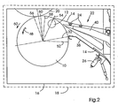
- Figure 2 is used to explain the method steps for mounting a printing master without speed change, which will be explained based on Figure 4 .
- the geometric aspects of the related components of the printing couple or printing unit 16 have already been explained with reference to Figure 1 .
- the press operator initiates the mounting operation by actuating a button or switch of the control unit of the printing couple or printing unit 16.
- An alarm sounds to indicate the start of the process, which starts with a time delay.
- the button of the control unit is to be actuated again.
- cooperating printing master cylinders 10 and blanket cylinders 20 are engaged with each other without engaging the two blanket cylinders 20. If a dismounting operation has just been carried out, the steps that have just been described can be dispensed with.
- the movement of the printing master cylinder 10 may immediately be started in the following manner.
- the printing master cylinder is set into a forward motion in the direction of rotation 48 at a first speed 50, for example 3 meters per minute.
- the fixing effect of the holding elements 24, e.g. the suction effect of suction nozzles, for the printing master 14 to be received is activated.
- the printing master changing device 22 is engaged with the printing master cylinder 10 in the printing master mounting position, and the printing master 14 is pressed onto the printing master cylinder 10.
- the leading edge of the printing master 14 enters the locking gap 12, so that the printing master 14 is entrained with and by the rotating printing master cylinder 10.
- phase position 54 the receiving device, in particular the first receiving element for the leading edge, is closed, so that the leading edge of the printing master 14 is held.
- phase position 56 the fixing effect of the holding elements 24 is switched off, so that the printing master 14 may be released by the printing master changing device.
- phase position 58 further on in the direction of rotation 48, the receiving device, in particular the second receiving element, is opened to insert the trailing edge of the printing master 14.
- a phase position 60 the receiving device, in particular the second receiving element, is closed when the locking gap 12 is located essentially in the extreme position or point of the volume between both cylinders limited by the two cylinders' circumferential surfaces and a tangent plane touching both cylinders' circumferential surfaces (wedge volume), in particular in the point of contact between the printing master cylinder 10 and the blanket cylinder 20, so that the printing master 14 is extended or tensioned and the trailing edge of the printing master 14 is pushed into the locking gap 12 by the blanket cylinder 20.
- the phase position 56 is reached again, the rotation of the cylinder is stopped, the printing master changing device 22 is disengaged, and the mounting operation is completed.
- Figure 3 again shows the printing master cylinder 10 with the blanket cylinder 20 in the printing couple or printing unit 16 of the web-fed printing press 18.
- This figure is dedicated to explaining the speed variations for dismounting the printing master 10 in accordance with the invention.
- the printing master cylinder 10 is set into a backward motion in the counterdirection of rotation 28 at a first speed 30, for example 3 meters per minute, in a phase position 34 (the angle relative to the zero position 32 of the press) of the locking gap 12.
- the rotary speed is reduced to a second speed, for example 1 meter per minute, in a third phase position 62, after the printing master changing device 22 has been engaged with the printing master cylinder 10.
- the printing master cylinder 10 rotates only at the reduced second speed, which has the advantages as mentioned above.
- the speed is increased again in a fourth phase position 64, in particular to the value of the first speed 30.
- the rotary speed of the printing master cylinder 10 is reduced to a third speed, which may or may not essentially correspond to the second speed and may, for example, be 0.5 meters per minute.
- the leading edge of the printing master 14 is released.
- the speed is increased again, in particular to the value of the first speed 30. The dismounting operation is completed in the way already described with reference to Figure 1 .
- Figure 4 also shows the printing master cylinder 10 with the blanket cylinder 20 in the printing couple or printing unit 16 of the web-fed printing press 18.
- This figure is dedicated to explaining the speed variations according to the invention for the mounting of a printing master 14.
- the printing master cylinder 10 is set into a forward motion in the direction of rotation 48 at a first speed 50, for example 3 meters per minute.
- the printing master changing device 22 is engaged with the printing master cylinder 10.
- the rotary speed is then reduced to a second speed, for example 0.5 meters per minute, in a third phase position 70.
- the speed is increased again, in particular to the value of the first speed 30, in a fourth phase position 72.
- the locking gap passes the phase position 56 and reaches a fifth phase position 74, in which the rotary speed of the printing master cylinder 10 is reduced to a third speed, which may or may not essentially correspond to the second speed and may be 0.5 meters per minute, for example. Consequently, the second receiving element can be closed as described with reference to Figure 2 to lock the trailing edge, but at a reduced speed, which has the advantages mentioned above.
- the rotary speed of the printing master cylinder is reduced as at least one receiving element for the leading edge or the trailing edge of the printing master is opened or closed to provide a reliable locking or a reliable release of the locking action, as it has been described based on the embodiment of the method according to the invention shown in the figures.
Landscapes
- Inking, Control Or Cleaning Of Printing Machines (AREA)
- Supply, Installation And Extraction Of Printed Sheets Or Plates (AREA)
- Manufacture Or Reproduction Of Printing Formes (AREA)
Abstract
Description
- The invention relates to a method of changing the mounting condition of a printing master on a printing master cylinder according to the preamble of claim 1.
-
US-5,363,764 andUS-A-2003/94111 disclose methods for changing the printing master of a printing master cylinder. - To reproduce various printing images in a printing press, printing image carriers generally referred to as printing masters or printing plates, with varying contents are mounted to printing master cylinders in the printing units of the printing press. To mount and dismount a printing master, the printing master cylinder is rotated at a constant speed. Receiving elements, which may be integrated, if desired, to form a mounting device, are provided for the leading edge and the trailing edge of the printing master. The receiving elements are actuated to lock or release the leading edge and the trailing edge, respectively, of the printing master in anticipation of the required phase position (i.e. the rotary position, the angular position, or the orientation) of the printing master cylinder relative to a zero position of the press or a point of contact with a transfer cylinder or a printing master changing device.
- The document
JP 2000-272096A - It is an object of the present invention to provide a method of changing the mounting condition of a printing master on a printing master cylinder to be carried out quickly while allowing an extended period of timer for the actuation of receiving elements.
- It is an object of the present invention to provide a method of changing the mounting condition of a printing master on a printing master cylinder to be carried out quickly while allowing an extended period of time for the actuation of receiving elements.
- According to the invention, this object is attained by a method of changing the mounting condition of a printing master on a printing master cylinder with the features set forth in claim 1. Advantageous embodiments of the invention are characterized in the dependent claims.
- In the method according to the invention of changing the mounting condition of a printing master on a printing master cylinder having a first receiving element for the leading edge and a second receiving element for the trailing edge of the printing master, the printing master cylinder is rotated at a first speed. In at least one phase position (at a first instant), the first receiving element is actuated, and in at least one second phase position (at a second instant), the second receiving element is actuated. At least during the period of time between a third phase position (at a third instant) and a fourth phase position (at a fourth instant), the printing master cylinder is rotated at a second speed that differs from the first speed. As a printing master is mounted, the speed is reduced after the printing master has been brought into contact with the printing master cylinder, and the speed is increased after the first receiving element for the leading has been closed. As a printing master is dismounted, the speed is reduced to a first value after holding elements have been brought into contact with the printing master and the speed is increased after the second receiving element has been opened.
- The speeds are not zero. The second speed is preferably lower than the first speed. The second speed may be close to zero. The receiving elements may be clamping elements. The receiving elements may be integrated to form a receiving device. The mounting condition (i.e. the manner in which the printing master is fixed or locked in position) may be at least one first condition in which the printing master is fixed, received, or locked on the printing master cylinder, and at least one second condition, in which the printing master is not located on the printing master cylinder. At least one of the receiving elements is actuated in the period of time between the third phase position and the fourth phase position. In other words, the third instant occurs before the first instant and/or the second instant, whereas the fourth instant occurs later.
- In the method according to the invention, the change of the mounting condition may consist of mounting or dismounting a printing master.
- The invention advantageously provides a simplification of an anticipation or a precontrol of the motion of the actuators for the receiving elements: if the speed is reduced during the period of time between the third and fourth phase positions, the window of time for actuating one or both of the receiving elements may be increased. Thus in the case of a mounting operation the locking, in particular the insertion of the trailing edge of the printing master, and in the case of a dismounting operation the release becomes more precise and more reliable.
- Furthermore, as the material ages, the mechanical parts of the receiving elements are subject to variations caused by dirt, wear, sticking together, or a change in the actuating time of electrical sliders. These deviations in the actuating, control, and activation behavior of the receiving elements can advantageously be counteracted by changing the rotary speed of the printing master cylinder at precisely the instant when the rotary movement is matched with the actuation of the receiving elements. Even after prolonged use of the printing press, a printing master can thus be mounted and dismounted in a reliable, precise manner, and in particular, the trailing edge of the printing master can be reliably gripped and released.
- The method according to the invention is particularly advantageous for a printing press with printing units that are individually driven and permit a printing master change in individual printing units independently of the others. The rotary speeds of every printing master cylinder can be individually selected, and every printing master cylinder of the number of printing master cylinders can be moved at the second speed in different third and fourth phase positions. In connection with the method according to the invention, the principle of individual drives provides a high degree of flexibility for the mounting and dismounting of printing masters. Moreover, the first speed, which is not relevant to the actuation of the receiving elements and consequently for the precision of the method as it is carried out, can advantageously be increased, whereas the second speed is selected to ensure that the change in the mounting condition (in particular locking or releasing the trailing edge and locking or releasing the leading edge of the printing master) is carried out in a reliable manner.
- According to a further development of the idea of the invention, further phase positions, or, to be more precise, pairs of phase positions, may be provided, and in between these phase positions, the printing master cylinder may be rotated at further different speeds, in particular at speeds that are lower than the speed used for the major part of the angular path to be moved through. According to the method of the invention, the printing master may additionally or alternatively be fed to a printing master changing device as the printing master is dismounted or the printing master may be taken from a printing master changing device as it is mounted.
- In the first embodiment of the method according to the invention, additionally or alternatively, the speed is reduced after a holding element for holding the printing master has been disengaged and before the trailing edge is inserted into the second receiving element.
- In the second embodiment of the method according to the invention, additionally or alternatively, the speed is reduced to a second value after a part of the printing master has already been removed from the printing master cylinder, and the speed is increased after the first receiving element has been opened. In an advantageous further development, the speed is increased essentially to the value it had before it was reduced.
- The idea of the invention also relates to a method of changing printing masters on a printing master cylinder. In the method according to the invention, a first printing master is dismounted from the printing master cylinder and a second printing master is mounted to the printing master cylinder. The dismounting of the first printing master and/or the mounting of the second printing master are carried out in accordance with a method according to the invention as disclosed in the present application.
- The method according to the invention or one of its further developments can advantageously be carried out in a printing unit of a printing press in the following manner: in a printing unit according to the invention and including at least one printing master cylinder and a control unit having a processing unit with a memory, a control program for the printing unit is stored in the memory. The control program comprises at least one part that controls a method according to the invention of changing the mounting condition of a printing master on the printing master cylinder or a method according to the invention of changing printing masters on the printing master cylinder as the part of the program is carried out by the processing unit. The speeds between the individual phase positions of the printing master cylinder as indicated and described may be settable, predeterminable, or changeable by means of the control unit. The printing unit according to the invention may be a direct or indirect lithographic printing unit, an offset printing unit, a dry offset printing unit, a flexographic printing unit, a gravure printing unit, or the like. A printing unit according to the invention can be used in a particularly advantageous manner in a printing press.
- A printing press according to the invention is characterized by at least one printing unit according to the invention and may be a web-fed or sheet-fed printing press. Typical printing stock is paper, cardboard, paperboard, organic polymer foil, or fabric, or the like. A web-fed printing press may be a commercial printing press or a newspaper press and may comprise a splicer, a number of printing units with an upper and a lower printing couple (typically four printing units), a drier and chill unit, and a folder. A sheet-fed printing press may be a perfecting press and may comprise a feeder, a number of printing units (typically four, six, eight, or ten), a finishing unit, if desired (an embossing or varnishing unit or the like), and a delivery.
- Other advantages and advantageous embodiments and refinements of the invention will be explained on the basis of the following figures and their descriptions.
- Figure 1
- is used to explain the method steps without speed changes to dismount a printing master in one embodiment at a lower printing master cylinder in a printing unit of a web-fed printing press,
- Figure 2
- is used to explain the method steps without speed changes for mounting a printing master in one embodiment at a lower printing master cylinder in a printing unit of a web-fed printing press,
- Figure 3
- is used to illustrate an advantageous embodiment of the dismounting method according to the invention with the steps explained with reference to
Figure 1 , and - Figure 4
- is used to illustrate an advantageous embodiment of the dismounting method according to the invention with the steps explained with reference to
Figure 2 . -
Figure 1 shows a lowerprinting master cylinder 10 having alocking gap 12 in which receiving elements (not further illustrated here) for the leading edge and the trailing edge of theprinting master 14 are located. The receiving elements are integrated to form a receiving device. Theprinting master cylinder 10 is part of a printing couple orprinting unit 16 of a web-fedprinting press 18. Receiving elements of this kind are disclosed inUS 6,601,509 ,US 6,601,508 ,US 6,463,852 ,US 6,047,641 , andUS 5,749,297 , for example, which are incorporated by reference herein. Theprinting master cylinder 10 may be engaged with a transfer cylinder orblanket cylinder 20.Figure 1 shows a printingform changing device 22 with suction heads as holdingelements 24 for feeding a printing master. The printingmaster changing device 22 also includes asensor 26 for detecting the presence of a dismountedprinting master 14. The method steps for dismounting aprinting master 14 without speed changes will be explained based onFigure 1 .Figure 3 will be used to describe the speed changes. - A press operator initiates the dismounting operation by actuating a button or switch of a control unit. An alarm sounds to indicate the start of the operation, which starts with a time delay. After at least one pressure roller in the drier and at least one pressure roller in the unwinding device (splicer) have been engaged and after the web tension has been reduced to essentially zero in the splicer, the button of the control unit is to be actuated again. In a printing couple or
printing unit 16, cooperatingprinting master cylinders 10 andblanket cylinders 20 are engaged with each other without engaging the twoblanket cylinders 20. In a phase position 34 (the angle relative to the zeroposition 32 of the press) of the lockinggap 12, the printing master cylinder is set into a backward motion in the counterdirection ofrotation 28 at afirst speed 30, for example 3 meters per minute. At a first angle, which is not controllable or settable by the press operator, the printingmaster changing device 22 is engaged with theprinting master cylinder 10. In aphase position 36, the receiving device, in particular the second receiving element for the trailing edge of theprinting master 14, is opened. Due to the resilience of theprinting master 14 as it rests against the surface of theprinting master cylinder 10 in a curved manner, the trailing edge releases from the lockinggap 12 so that the trailing edge may move between afirst guide element 38 and asecond guide element 40 carrying the holdingelements 24. In aphase position 42, the receiving device is closed, in particular if the receiving element for the leading edge was opened with the second receiving element for the trailing edge. A further rotation in thecounterdirection 28 progressively moves theprinting master 14 into the printingmaster changing device 22. In aphase position 44, the receiving device, in particular the first receiving element for the leading edge of theprinting master 14, is opened, so that the leading edge is released, too. At a second angle, the trailing edge contacts a hook of the printingmaster changing device 22 and hits a stop. The leading edge releases from theprinting master cylinder 10. At aphase position 46, the rotation of theprinting master cylinder 10 is stopped and the receiving device is closed again. After a defined period of time, theprinting master 14 that has been dismounted is pulled between guides by means of a lift in order to remove theprinting master 14 from theprinting master cylinder 10 and to place it in a cartridge, a storage device. The press operator can retrieve it from there when the dismounting operation is completed. The next step is a verification or evaluation of whether the dismounting operation was successful: if the dismountedprinting master 14 is detected by thesensor 26, the operation continues without signaling a failure. If no printing master is detected, the operation is interrupted and an output device of the control unit outputs a message. The press operator must interfere to correct the error and to reset the control. A successful dismounting operation may be immediately followed by a mounting operation. -
Figure 2 is used to explain the method steps for mounting a printing master without speed change, which will be explained based onFigure 4 . The geometric aspects of the related components of the printing couple orprinting unit 16 have already been explained with reference toFigure 1 . - The press operator initiates the mounting operation by actuating a button or switch of the control unit of the printing couple or
printing unit 16. An alarm sounds to indicate the start of the process, which starts with a time delay. After at least one pressure roller in the drier and at least one pressure roller in the unwinding device (splicer) have been engaged and after the web tension has been reduced to essentially zero in the splicer, the button of the control unit is to be actuated again. In a printing couple, cooperatingprinting master cylinders 10 andblanket cylinders 20 are engaged with each other without engaging the twoblanket cylinders 20. If a dismounting operation has just been carried out, the steps that have just been described can be dispensed with. Instead, the movement of theprinting master cylinder 10 may immediately be started in the following manner. The printing master cylinder is set into a forward motion in the direction ofrotation 48 at afirst speed 50, for example 3 meters per minute. The fixing effect of the holdingelements 24, e.g. the suction effect of suction nozzles, for theprinting master 14 to be received is activated. In aphase position 52 of the locking gap 12 (relative to a zeroposition 32 of the press) the printingmaster changing device 22 is engaged with theprinting master cylinder 10 in the printing master mounting position, and theprinting master 14 is pressed onto theprinting master cylinder 10. At a third angle, the leading edge of theprinting master 14 enters the lockinggap 12, so that theprinting master 14 is entrained with and by the rotatingprinting master cylinder 10. In aphase position 54, the receiving device, in particular the first receiving element for the leading edge, is closed, so that the leading edge of theprinting master 14 is held. In aphase position 56, the fixing effect of the holdingelements 24 is switched off, so that theprinting master 14 may be released by the printing master changing device. In aphase position 58 further on in the direction ofrotation 48, the receiving device, in particular the second receiving element, is opened to insert the trailing edge of theprinting master 14. In aphase position 60, the receiving device, in particular the second receiving element, is closed when the lockinggap 12 is located essentially in the extreme position or point of the volume between both cylinders limited by the two cylinders' circumferential surfaces and a tangent plane touching both cylinders' circumferential surfaces (wedge volume), in particular in the point of contact between theprinting master cylinder 10 and theblanket cylinder 20, so that theprinting master 14 is extended or tensioned and the trailing edge of theprinting master 14 is pushed into the lockinggap 12 by theblanket cylinder 20. When thephase position 56 is reached again, the rotation of the cylinder is stopped, the printingmaster changing device 22 is disengaged, and the mounting operation is completed. - After the phase positions of the individual operations for dismounting and mounting a
printing master 14 have been described with reference toFigures 1 and2 , the variation of the rotary speeds of theprinting master cylinder 10 as suggested by the invention will be explained below with reference toFigures 3 and4 . -
Figure 3 again shows theprinting master cylinder 10 with theblanket cylinder 20 in the printing couple orprinting unit 16 of the web-fedprinting press 18. This figure is dedicated to explaining the speed variations for dismounting theprinting master 10 in accordance with the invention. As mentioned above, to dismount theprinting master 14, theprinting master cylinder 10 is set into a backward motion in the counterdirection ofrotation 28 at afirst speed 30, for example 3 meters per minute, in a phase position 34 (the angle relative to the zeroposition 32 of the press) of the lockinggap 12. According to the invention, the rotary speed is reduced to a second speed, for example 1 meter per minute, in athird phase position 62, after the printingmaster changing device 22 has been engaged with theprinting master cylinder 10. Thus in thephase position 36, when the receiving device is opened, theprinting master cylinder 10 rotates only at the reduced second speed, which has the advantages as mentioned above. After releasing the trailing edge of the printing master, the speed is increased again in afourth phase position 64, in particular to the value of thefirst speed 30. After thephase position 42, in afifth phase position 66, the rotary speed of theprinting master cylinder 10 is reduced to a third speed, which may or may not essentially correspond to the second speed and may, for example, be 0.5 meters per minute. After further rotation in thecounterdirection 28, in particular after passing thephase position 44, the leading edge of theprinting master 14 is released. In asixth phase position 68, the speed is increased again, in particular to the value of thefirst speed 30. The dismounting operation is completed in the way already described with reference toFigure 1 . -
Figure 4 also shows theprinting master cylinder 10 with theblanket cylinder 20 in the printing couple orprinting unit 16 of the web-fedprinting press 18. This figure is dedicated to explaining the speed variations according to the invention for the mounting of aprinting master 14. As described with reference toFigure 2 , theprinting master cylinder 10 is set into a forward motion in the direction ofrotation 48 at afirst speed 50, for example 3 meters per minute. In aphase position 52, the printingmaster changing device 22 is engaged with theprinting master cylinder 10. According to the invention, the rotary speed is then reduced to a second speed, for example 0.5 meters per minute, in athird phase position 70. After thephase position 54, in which the receiving device, in particular the first receiving element for the trailing edge, is closed, the speed is increased again, in particular to the value of thefirst speed 30, in a fourth phase position 72. As theprinting master cylinder 10 now rotates through more than one complete revolution, the locking gap passes thephase position 56 and reaches a fifth phase position 74, in which the rotary speed of theprinting master cylinder 10 is reduced to a third speed, which may or may not essentially correspond to the second speed and may be 0.5 meters per minute, for example. Consequently, the second receiving element can be closed as described with reference toFigure 2 to lock the trailing edge, but at a reduced speed, which has the advantages mentioned above. - In short, the rotary speed of the printing master cylinder is reduced as at least one receiving element for the leading edge or the trailing edge of the printing master is opened or closed to provide a reliable locking or a reliable release of the locking action, as it has been described based on the embodiment of the method according to the invention shown in the figures.
- List of Reference Numerals
- 10
- printing master cylinder
- 12
- locking gap
- 14
- printing master
- 16
- printing couple
- 18
- web-fed printing press
- 20
- blanket cylinder
- 22
- printing master changing device
- 24
- holding element
- 26
- sensor
- 28
- counterdirection of rotation
- 30
- first speed
- 32
- zero position of the press
- 34
- phase position
- 36
- phase position
- 38
- first guide element
- 40
- second guide element
- 42
- phase position
- 44
- phase position
- 46
- phase position
- 48
- direction of rotation
- 50
- first speed
- 52
- phase position
- 54
- phase position
- 56
- phase position
- 58
- phase position
- 60
- phase position
- 62
- third phase position
- 64
- fourth phase position
- 66
- fifth phase position
- 68
- sixth phase position
- 70
- third phase position
- 72
- fourth phase position
- 74
- fifth phase position
Claims (13)
- Method of changing the mounting condition of a printing master (14) on a printing master cylinder (10) including a first receiving element for the leading edge and a second receiving element for the trailing edge of the printing master (14), wherein the printing master cylinder (10) is rotated at a first speed and the first receiving element is actuated in at least one first phase position and the second receiving element is actuated in at least one second phase position,
wherein the printing master cylinder (10) is rotated at a second speed, which differs from the first speed, at least between a third phase position (62, 70) and
a fourth phase position (64, 72)
wherein, for mounting a printing master(14), it comprises the steps:m1) the speed is reduced after the printing master (14) has been engaged with the printing master cylinder (10),m2) the speed is increased after the first receiving element for the leading edge has been closed, andm3) before the second receiving element is closed to lock the trailing edge, the speed of the printing master cylinder is reduced,and/or that for dismounting a printing master (14), it comprises_the steps:d1) the speed is reduced to a first value after holding elements (24) of a form changing device (22) have been engaged with the printing master (14), andd2) the speed is increased after the second receiving element has been opened. - Method according to claim 1,
characterized in
that further phase positions (66, 68) are provided, between which the printing master cylinder (10) is rotated at further different speeds. - Method according to claim 1 or 2,
characterized in
that the change of the mounting condition consists of mounting or dismounting a printing master (14). - Method according to claim 3,
characterized in
that the printing master (14) is fed to a printing master changing device (22) as it is dismounted or that the printing master (14) is taken from a printing master changing device (22) as it is mounted. - Method according to one of the preceding claims,
characterized in
that when a printing master (14) is mounted,the speed is reduced after a holding element (24) of the printing master (14) has been disengaged and before the trailing edge is inserted into the second receiving element. - Method according to one of the preceding claims,
characterized in
that when a printing master (14) is dismounted, the speed is reduced (66) to a second value after a part of the printing master (14) has been removed from the printing master cylinder (10) and the speed is increased (68) after the first receiving element has been opened. - Method according to claim 6,
characterized in
that the speed is increased essentially to the value it had before it was reduced. - Method according to one of the preceding claims,
characterized in
that when a printing master (14) is mounted, step m2 takes place before step m3. - Method according to one of the preceding claims,
characterized in
that the speeds are not zero. - Method according to one of the preceding claims,
characterized in
that, during mounting, the rotary speed of the printing master cylinder is reduced as the first and/or the second receiving element is closed, and/or that during dismounting, the rotary speed of the printing master cylinder is reduced as the first and/or the second receiving element is opened. - Method of changing printing masters (14) on a printing master cylinder (10) with a first printing master (14) being dismounted from the printing master cylinder (10) and a second printing master (14) being mounted to the printing master cylinder (10),
characterized in
that the dismounting of the first printing master (14) and/or the mounting of the second printing master (14) is carried out in accordance with a method as set forth in one of the preceding claims. - Printing unit (16) having- at least one printing master cylinder (10),- a form changing with holding elements,- a first receiving element for the leading edge and a second receiving element for the trailing edge of the printing master located on the printing master cylinder, and- a control unit that includes a processing unit and a memory,
characterized in
that the memory contains a printing unit (16) control program including at least one part that, as it is carried out by the processing unit of the control unit, is adapted to control a method of changing the mounting condition of a printing master (14) on the printing master cylinder (10) in accordance with one of the preceding claims 1 to 9 or a method of changing printing masters (14) on the printing master cylinder (10) in accordance with claim 11. - Printing press (18), characterized by
at least one printing unit (16) in accordance with claim 12.
Applications Claiming Priority (2)
| Application Number | Priority Date | Filing Date | Title |
|---|---|---|---|
| DE10342740A DE10342740A1 (en) | 2003-09-16 | 2003-09-16 | Method for changing the mounting state of a printing form on a printing form cylinder |
| PCT/EP2004/010247 WO2005025870A1 (en) | 2003-09-16 | 2004-09-14 | Method of changing the mounting condition of a printing master on a printing master cylinder |
Publications (2)
| Publication Number | Publication Date |
|---|---|
| EP1663650A1 EP1663650A1 (en) | 2006-06-07 |
| EP1663650B1 true EP1663650B1 (en) | 2011-11-02 |
Family
ID=34305809
Family Applications (1)
| Application Number | Title | Priority Date | Filing Date |
|---|---|---|---|
| EP04765162A Expired - Lifetime EP1663650B1 (en) | 2003-09-16 | 2004-09-14 | Method of changing the mounting condition of a printing master on a printing master cylinder |
Country Status (6)
| Country | Link |
|---|---|
| US (1) | US7637209B2 (en) |
| EP (1) | EP1663650B1 (en) |
| JP (1) | JP2007505765A (en) |
| AT (1) | ATE531520T1 (en) |
| DE (1) | DE10342740A1 (en) |
| WO (1) | WO2005025870A1 (en) |
Families Citing this family (3)
| Publication number | Priority date | Publication date | Assignee | Title |
|---|---|---|---|---|
| DE10342740A1 (en) | 2003-09-16 | 2005-04-21 | Goss Int Montataire Sa | Method for changing the mounting state of a printing form on a printing form cylinder |
| USD584903S1 (en) | 2006-12-13 | 2009-01-20 | Waterloo Industries, Inc. | Tool cabinet |
| USD589718S1 (en) | 2006-12-13 | 2009-04-07 | Waterloo Industries, Inc. | Tool chest and cabinet |
Family Cites Families (17)
| Publication number | Priority date | Publication date | Assignee | Title |
|---|---|---|---|---|
| DE4205436C2 (en) * | 1991-03-07 | 1994-05-26 | Heidelberger Druckmasch Ag | Device for clamping a printing plate or the like on a cylinder of a rotary printing press |
| US5272977A (en) * | 1992-02-05 | 1993-12-28 | Toshiba Kikai Kabushiki Kaisha | Printing plate mounting apparatus, printing plate replacement apparatus and printing plate replacement method |
| DE4338664C2 (en) * | 1993-11-12 | 1995-09-14 | Roland Man Druckmasch | Method and device for controlling an automated printing plate changing process in printing machines |
| FR2732268B1 (en) * | 1995-03-31 | 1997-06-20 | Heidelberg Harris Sa | DEVICE FOR EXCHANGING PRINTING PLATES |
| FR2733718B1 (en) * | 1995-05-04 | 1997-08-01 | Heidelberg Harris Sa | CONNECTION DEVICE BETWEEN RETAINING ELEMENTS AND A TRANSMISSION OF A PRINTING SHAPE CYLINDER |
| US5492062A (en) * | 1995-05-08 | 1996-02-20 | Heidelberg Druckmaschinen Ag | Printing cylinder positioning device and method |
| JP3059112B2 (en) * | 1997-01-13 | 2000-07-04 | リョービ株式会社 | Plate edge insertion device for printing press |
| JPH1120132A (en) * | 1997-07-04 | 1999-01-26 | Shinano Kenshi Co Ltd | Automatic plate feeding mechanism for offset printing equipment |
| FR2776567B1 (en) * | 1998-03-31 | 2000-06-16 | Heidelberger Druckmasch Ag | DEVICE FOR HOLDING A PRINTING PLATE ON A PLATE-HOLDING CYLINDER OF A ROTARY PRINTING MACHINE |
| JP4436476B2 (en) * | 1999-03-25 | 2010-03-24 | アキヤマインターナショナル株式会社 | Plate plate attachment / detachment mechanism of sheet-fed printing press |
| ATE255502T1 (en) * | 1999-03-26 | 2003-12-15 | Heidelberger Druckmasch Ag | DEVICE FOR CLAMPING PRINTING PLATES IN REDUCED SIZE CLAMPING CHANNELS |
| DE10056167A1 (en) * | 1999-11-15 | 2001-05-17 | Heidelberger Druckmasch Ag | Tension device for indentation on surface of printing cylinder in printing apparatus of rotary printing press has locking and unlocking of tension element on tension shaft |
| US6348963B2 (en) * | 2000-01-25 | 2002-02-19 | Fuji Photo Film Co., Ltd. | Apparatus and method for processing sheet material and image recording apparatus |
| DE10060826A1 (en) * | 2000-12-07 | 2002-06-13 | Heidelberger Druckmasch Ag | Spring element for fixing printing forms to printing form cylinders |
| JP4604266B2 (en) * | 2001-03-27 | 2011-01-05 | 三菱重工印刷紙工機械株式会社 | Plate changing apparatus and plate changing method |
| DE10248689A1 (en) * | 2001-11-16 | 2003-05-28 | Heidelberger Druckmasch Ag | Automatic printing plate exchanging method for rotary press, involves clamping of printing plate onto plate cylinder at rendezvous speed and increasing speed of plate cylinder to printing speed |
| DE10342740A1 (en) | 2003-09-16 | 2005-04-21 | Goss Int Montataire Sa | Method for changing the mounting state of a printing form on a printing form cylinder |
-
2003
- 2003-09-16 DE DE10342740A patent/DE10342740A1/en not_active Withdrawn
-
2004
- 2004-09-14 AT AT04765162T patent/ATE531520T1/en active
- 2004-09-14 US US10/572,179 patent/US7637209B2/en not_active Expired - Fee Related
- 2004-09-14 WO PCT/EP2004/010247 patent/WO2005025870A1/en not_active Ceased
- 2004-09-14 JP JP2006526572A patent/JP2007505765A/en active Pending
- 2004-09-14 EP EP04765162A patent/EP1663650B1/en not_active Expired - Lifetime
Also Published As
| Publication number | Publication date |
|---|---|
| EP1663650A1 (en) | 2006-06-07 |
| DE10342740A1 (en) | 2005-04-21 |
| US7637209B2 (en) | 2009-12-29 |
| US20070022890A1 (en) | 2007-02-01 |
| WO2005025870A1 (en) | 2005-03-24 |
| ATE531520T1 (en) | 2011-11-15 |
| JP2007505765A (en) | 2007-03-15 |
Similar Documents
| Publication | Publication Date | Title |
|---|---|---|
| CA1325922C (en) | Printing unit for rotary printing presses | |
| JP4023629B2 (en) | Impression cylinder for sheet-fed printing machine | |
| US5048416A (en) | Multi-color printing apparatus | |
| JPH11320832A (en) | Feeding device installed in sheet-fed rotary printing press | |
| JPH0669749B2 (en) | Plate mounting method in printing machine | |
| JP4829529B2 (en) | Printer | |
| US20020084581A1 (en) | Printing unit with a holding device adjustable into the interior of a transport device | |
| US4311095A (en) | Cleaning device for printing-unit cylinders in offset printing machines | |
| US6345575B1 (en) | Pivotable printing-form changing device and method for changing printing forms | |
| US5738015A (en) | Device for guiding a print carrier | |
| JP2997084B2 (en) | Method for wet printing a printing plate | |
| GB1152761A (en) | Improvements in or relating to an Automated Duplicating Machine | |
| JP3779847B2 (en) | Stencil printing machine | |
| US7637209B2 (en) | Method of changing the mounting condition of a printing master on a printing master cylinder | |
| US6457407B2 (en) | Method and apparatus for adjusting cylinders in a printing machine | |
| EP0547753B1 (en) | Offset press | |
| US6425330B1 (en) | Method for changing a printing plate | |
| JPH07257003A (en) | Stencil printer | |
| US20040256796A1 (en) | Machine for processing printing material sheets, in particular sheet-fed printing press, and method of operating the machine | |
| US7000540B2 (en) | Method of operating a machine processing printing material sheets | |
| JPH04301457A (en) | Offset press | |
| JP2999048B2 (en) | Stencil printing machine | |
| US6655283B2 (en) | Method and device for fastening a printing plate to a plate cylinder of a rotary printing machine | |
| US10696041B2 (en) | Method and device for operating a rotary screen-printing machine | |
| EP2193027A1 (en) | Apparatus for detecting printing plates and a printing plate monitoring system for a printing press |
Legal Events
| Date | Code | Title | Description |
|---|---|---|---|
| PUAI | Public reference made under article 153(3) epc to a published international application that has entered the european phase |
Free format text: ORIGINAL CODE: 0009012 |
|
| 17P | Request for examination filed |
Effective date: 20060307 |
|
| AK | Designated contracting states |
Kind code of ref document: A1 Designated state(s): AT BE BG CH CY CZ DE DK EE ES FI FR GB GR HU IE IT LI LU MC NL PL PT RO SE SI SK TR |
|
| DAX | Request for extension of the european patent (deleted) | ||
| 17Q | First examination report despatched |
Effective date: 20070704 |
|
| GRAP | Despatch of communication of intention to grant a patent |
Free format text: ORIGINAL CODE: EPIDOSNIGR1 |
|
| GRAS | Grant fee paid |
Free format text: ORIGINAL CODE: EPIDOSNIGR3 |
|
| GRAA | (expected) grant |
Free format text: ORIGINAL CODE: 0009210 |
|
| AK | Designated contracting states |
Kind code of ref document: B1 Designated state(s): AT BE BG CH CY CZ DE DK EE ES FI FR GB GR HU IE IT LI LU MC NL PL PT RO SE SI SK TR |
|
| REG | Reference to a national code |
Ref country code: GB Ref legal event code: FG4D |
|
| REG | Reference to a national code |
Ref country code: DE Ref legal event code: R081 Ref document number: 602004035146 Country of ref document: DE Owner name: GOSS INTERNATIONAL LLC (N. D. GES. D. STAATES , US Free format text: FORMER OWNER: GOSS INTERNATIONAL MONTATAIRE S.A., MONTATAIRE, FR |
|
| REG | Reference to a national code |
Ref country code: CH Ref legal event code: EP |
|
| REG | Reference to a national code |
Ref country code: IE Ref legal event code: FG4D |
|
| REG | Reference to a national code |
Ref country code: DE Ref legal event code: R096 Ref document number: 602004035146 Country of ref document: DE Effective date: 20120105 |
|
| REG | Reference to a national code |
Ref country code: CH Ref legal event code: NV Representative=s name: KIRKER & CIE S.A. |
|
| REG | Reference to a national code |
Ref country code: NL Ref legal event code: VDEP Effective date: 20111102 |
|
| PG25 | Lapsed in a contracting state [announced via postgrant information from national office to epo] |
Ref country code: BE Free format text: LAPSE BECAUSE OF FAILURE TO SUBMIT A TRANSLATION OF THE DESCRIPTION OR TO PAY THE FEE WITHIN THE PRESCRIBED TIME-LIMIT Effective date: 20111102 Ref country code: GR Free format text: LAPSE BECAUSE OF FAILURE TO SUBMIT A TRANSLATION OF THE DESCRIPTION OR TO PAY THE FEE WITHIN THE PRESCRIBED TIME-LIMIT Effective date: 20120203 Ref country code: PT Free format text: LAPSE BECAUSE OF FAILURE TO SUBMIT A TRANSLATION OF THE DESCRIPTION OR TO PAY THE FEE WITHIN THE PRESCRIBED TIME-LIMIT Effective date: 20120302 Ref country code: NL Free format text: LAPSE BECAUSE OF FAILURE TO SUBMIT A TRANSLATION OF THE DESCRIPTION OR TO PAY THE FEE WITHIN THE PRESCRIBED TIME-LIMIT Effective date: 20111102 Ref country code: SI Free format text: LAPSE BECAUSE OF FAILURE TO SUBMIT A TRANSLATION OF THE DESCRIPTION OR TO PAY THE FEE WITHIN THE PRESCRIBED TIME-LIMIT Effective date: 20111102 Ref country code: SE Free format text: LAPSE BECAUSE OF FAILURE TO SUBMIT A TRANSLATION OF THE DESCRIPTION OR TO PAY THE FEE WITHIN THE PRESCRIBED TIME-LIMIT Effective date: 20111102 Ref country code: PL Free format text: LAPSE BECAUSE OF FAILURE TO SUBMIT A TRANSLATION OF THE DESCRIPTION OR TO PAY THE FEE WITHIN THE PRESCRIBED TIME-LIMIT Effective date: 20111102 |
|
| PG25 | Lapsed in a contracting state [announced via postgrant information from national office to epo] |
Ref country code: CY Free format text: LAPSE BECAUSE OF FAILURE TO SUBMIT A TRANSLATION OF THE DESCRIPTION OR TO PAY THE FEE WITHIN THE PRESCRIBED TIME-LIMIT Effective date: 20111102 |
|
| PG25 | Lapsed in a contracting state [announced via postgrant information from national office to epo] |
Ref country code: SK Free format text: LAPSE BECAUSE OF FAILURE TO SUBMIT A TRANSLATION OF THE DESCRIPTION OR TO PAY THE FEE WITHIN THE PRESCRIBED TIME-LIMIT Effective date: 20111102 Ref country code: CZ Free format text: LAPSE BECAUSE OF FAILURE TO SUBMIT A TRANSLATION OF THE DESCRIPTION OR TO PAY THE FEE WITHIN THE PRESCRIBED TIME-LIMIT Effective date: 20111102 Ref country code: EE Free format text: LAPSE BECAUSE OF FAILURE TO SUBMIT A TRANSLATION OF THE DESCRIPTION OR TO PAY THE FEE WITHIN THE PRESCRIBED TIME-LIMIT Effective date: 20111102 Ref country code: DK Free format text: LAPSE BECAUSE OF FAILURE TO SUBMIT A TRANSLATION OF THE DESCRIPTION OR TO PAY THE FEE WITHIN THE PRESCRIBED TIME-LIMIT Effective date: 20111102 Ref country code: BG Free format text: LAPSE BECAUSE OF FAILURE TO SUBMIT A TRANSLATION OF THE DESCRIPTION OR TO PAY THE FEE WITHIN THE PRESCRIBED TIME-LIMIT Effective date: 20120202 |
|
| PG25 | Lapsed in a contracting state [announced via postgrant information from national office to epo] |
Ref country code: RO Free format text: LAPSE BECAUSE OF FAILURE TO SUBMIT A TRANSLATION OF THE DESCRIPTION OR TO PAY THE FEE WITHIN THE PRESCRIBED TIME-LIMIT Effective date: 20111102 Ref country code: IT Free format text: LAPSE BECAUSE OF FAILURE TO SUBMIT A TRANSLATION OF THE DESCRIPTION OR TO PAY THE FEE WITHIN THE PRESCRIBED TIME-LIMIT Effective date: 20111102 |
|
| PLBE | No opposition filed within time limit |
Free format text: ORIGINAL CODE: 0009261 |
|
| STAA | Information on the status of an ep patent application or granted ep patent |
Free format text: STATUS: NO OPPOSITION FILED WITHIN TIME LIMIT |
|
| REG | Reference to a national code |
Ref country code: AT Ref legal event code: MK05 Ref document number: 531520 Country of ref document: AT Kind code of ref document: T Effective date: 20111102 |
|
| 26N | No opposition filed |
Effective date: 20120803 |
|
| REG | Reference to a national code |
Ref country code: DE Ref legal event code: R097 Ref document number: 602004035146 Country of ref document: DE Effective date: 20120803 |
|
| PG25 | Lapsed in a contracting state [announced via postgrant information from national office to epo] |
Ref country code: AT Free format text: LAPSE BECAUSE OF FAILURE TO SUBMIT A TRANSLATION OF THE DESCRIPTION OR TO PAY THE FEE WITHIN THE PRESCRIBED TIME-LIMIT Effective date: 20111102 |
|
| PG25 | Lapsed in a contracting state [announced via postgrant information from national office to epo] |
Ref country code: MC Free format text: LAPSE BECAUSE OF NON-PAYMENT OF DUE FEES Effective date: 20120930 Ref country code: ES Free format text: LAPSE BECAUSE OF FAILURE TO SUBMIT A TRANSLATION OF THE DESCRIPTION OR TO PAY THE FEE WITHIN THE PRESCRIBED TIME-LIMIT Effective date: 20120213 |
|
| REG | Reference to a national code |
Ref country code: IE Ref legal event code: MM4A |
|
| PG25 | Lapsed in a contracting state [announced via postgrant information from national office to epo] |
Ref country code: FI Free format text: LAPSE BECAUSE OF FAILURE TO SUBMIT A TRANSLATION OF THE DESCRIPTION OR TO PAY THE FEE WITHIN THE PRESCRIBED TIME-LIMIT Effective date: 20111102 |
|
| PG25 | Lapsed in a contracting state [announced via postgrant information from national office to epo] |
Ref country code: IE Free format text: LAPSE BECAUSE OF NON-PAYMENT OF DUE FEES Effective date: 20120914 |
|
| PGFP | Annual fee paid to national office [announced via postgrant information from national office to epo] |
Ref country code: GB Payment date: 20130927 Year of fee payment: 10 |
|
| PGFP | Annual fee paid to national office [announced via postgrant information from national office to epo] |
Ref country code: CH Payment date: 20130927 Year of fee payment: 10 |
|
| PG25 | Lapsed in a contracting state [announced via postgrant information from national office to epo] |
Ref country code: TR Free format text: LAPSE BECAUSE OF FAILURE TO SUBMIT A TRANSLATION OF THE DESCRIPTION OR TO PAY THE FEE WITHIN THE PRESCRIBED TIME-LIMIT Effective date: 20111102 |
|
| PG25 | Lapsed in a contracting state [announced via postgrant information from national office to epo] |
Ref country code: LU Free format text: LAPSE BECAUSE OF NON-PAYMENT OF DUE FEES Effective date: 20120914 |
|
| PG25 | Lapsed in a contracting state [announced via postgrant information from national office to epo] |
Ref country code: HU Free format text: LAPSE BECAUSE OF FAILURE TO SUBMIT A TRANSLATION OF THE DESCRIPTION OR TO PAY THE FEE WITHIN THE PRESCRIBED TIME-LIMIT Effective date: 20040914 |
|
| REG | Reference to a national code |
Ref country code: CH Ref legal event code: PL |
|
| GBPC | Gb: european patent ceased through non-payment of renewal fee |
Effective date: 20140914 |
|
| PG25 | Lapsed in a contracting state [announced via postgrant information from national office to epo] |
Ref country code: LI Free format text: LAPSE BECAUSE OF NON-PAYMENT OF DUE FEES Effective date: 20140930 Ref country code: GB Free format text: LAPSE BECAUSE OF NON-PAYMENT OF DUE FEES Effective date: 20140914 Ref country code: CH Free format text: LAPSE BECAUSE OF NON-PAYMENT OF DUE FEES Effective date: 20140930 |
|
| REG | Reference to a national code |
Ref country code: FR Ref legal event code: PLFP Year of fee payment: 13 |
|
| REG | Reference to a national code |
Ref country code: DE Ref legal event code: R082 Ref document number: 602004035146 Country of ref document: DE Representative=s name: LIEB, FABIAN, MSC (UNIV. OF LONDON), DE Ref country code: DE Ref legal event code: R081 Ref document number: 602004035146 Country of ref document: DE Owner name: GOSS INTERNATIONAL LLC (N. D. GES. D. STAATES , US Free format text: FORMER OWNER: GOSS INTERNATIONAL MONTATAIRE S.A., MONTATAIRE, FR Ref country code: DE Ref legal event code: R082 Ref document number: 602004035146 Country of ref document: DE Representative=s name: LAVOIX MUNICH, DE |
|
| REG | Reference to a national code |
Ref country code: FR Ref legal event code: PLFP Year of fee payment: 14 |
|
| REG | Reference to a national code |
Ref country code: DE Ref legal event code: R082 Ref document number: 602004035146 Country of ref document: DE Representative=s name: LAVOIX MUNICH, DE |
|
| REG | Reference to a national code |
Ref country code: FR Ref legal event code: PLFP Year of fee payment: 15 |
|
| PGFP | Annual fee paid to national office [announced via postgrant information from national office to epo] |
Ref country code: DE Payment date: 20180927 Year of fee payment: 15 Ref country code: FR Payment date: 20180925 Year of fee payment: 15 |
|
| REG | Reference to a national code |
Ref country code: DE Ref legal event code: R119 Ref document number: 602004035146 Country of ref document: DE |
|
| PG25 | Lapsed in a contracting state [announced via postgrant information from national office to epo] |
Ref country code: DE Free format text: LAPSE BECAUSE OF NON-PAYMENT OF DUE FEES Effective date: 20200401 |
|
| PG25 | Lapsed in a contracting state [announced via postgrant information from national office to epo] |
Ref country code: FR Free format text: LAPSE BECAUSE OF NON-PAYMENT OF DUE FEES Effective date: 20190930 |