EP1663453B1 - Gas-flüssigkeitkontaktboden - Google Patents
Gas-flüssigkeitkontaktboden Download PDFInfo
- Publication number
- EP1663453B1 EP1663453B1 EP04766330A EP04766330A EP1663453B1 EP 1663453 B1 EP1663453 B1 EP 1663453B1 EP 04766330 A EP04766330 A EP 04766330A EP 04766330 A EP04766330 A EP 04766330A EP 1663453 B1 EP1663453 B1 EP 1663453B1
- Authority
- EP
- European Patent Office
- Prior art keywords
- liquid
- tray
- downcomer
- gas
- downcomers
- Prior art date
- Legal status (The legal status is an assumption and is not a legal conclusion. Google has not performed a legal analysis and makes no representation as to the accuracy of the status listed.)
- Expired - Lifetime
Links
- 239000007788 liquid Substances 0.000 title claims abstract description 177
- 238000004821 distillation Methods 0.000 description 5
- 238000009826 distribution Methods 0.000 description 4
- 238000005452 bending Methods 0.000 description 3
- 238000005520 cutting process Methods 0.000 description 3
- 238000004519 manufacturing process Methods 0.000 description 3
- 238000004080 punching Methods 0.000 description 3
- 230000003247 decreasing effect Effects 0.000 description 2
- 238000005194 fractionation Methods 0.000 description 2
- 230000003116 impacting effect Effects 0.000 description 2
- 239000002184 metal Substances 0.000 description 2
- 238000000034 method Methods 0.000 description 2
- 238000012856 packing Methods 0.000 description 2
- 230000035515 penetration Effects 0.000 description 2
- 230000008569 process Effects 0.000 description 2
- 238000000926 separation method Methods 0.000 description 2
- 238000010521 absorption reaction Methods 0.000 description 1
- 230000004888 barrier function Effects 0.000 description 1
- 230000008901 benefit Effects 0.000 description 1
- 230000008859 change Effects 0.000 description 1
- 238000009833 condensation Methods 0.000 description 1
- 230000005494 condensation Effects 0.000 description 1
- 239000012530 fluid Substances 0.000 description 1
- 230000007246 mechanism Effects 0.000 description 1
- 238000002156 mixing Methods 0.000 description 1
- 238000010992 reflux Methods 0.000 description 1
- 239000007787 solid Substances 0.000 description 1
- 238000003892 spreading Methods 0.000 description 1
- 230000007480 spreading Effects 0.000 description 1
Images
Classifications
-
- B—PERFORMING OPERATIONS; TRANSPORTING
- B01—PHYSICAL OR CHEMICAL PROCESSES OR APPARATUS IN GENERAL
- B01D—SEPARATION
- B01D3/00—Distillation or related exchange processes in which liquids are contacted with gaseous media, e.g. stripping
- B01D3/14—Fractional distillation or use of a fractionation or rectification column
- B01D3/16—Fractionating columns in which vapour bubbles through liquid
- B01D3/18—Fractionating columns in which vapour bubbles through liquid with horizontal bubble plates
- B01D3/20—Bubble caps; Risers for vapour; Discharge pipes for liquid
-
- B—PERFORMING OPERATIONS; TRANSPORTING
- B01—PHYSICAL OR CHEMICAL PROCESSES OR APPARATUS IN GENERAL
- B01D—SEPARATION
- B01D53/00—Separation of gases or vapours; Recovering vapours of volatile solvents from gases; Chemical or biological purification of waste gases, e.g. engine exhaust gases, smoke, fumes, flue gases, aerosols
- B01D53/14—Separation of gases or vapours; Recovering vapours of volatile solvents from gases; Chemical or biological purification of waste gases, e.g. engine exhaust gases, smoke, fumes, flue gases, aerosols by absorption
- B01D53/18—Absorbing units; Liquid distributors therefor
Definitions
- Such a tray is normally horizontally mounted in a vertical column, and the terms upward, downward, top, and bottom are used in the specification and in the claims with reference to this normal tray arrangement.
- the vertical column can for example be a column for counter-currently contacting gas and liquid, such as a fractionation column, wherein a plurality of similar trays are vertically stacked.
- Each of such trays normally comprises a bubble area, which is an area on the tray plate that is provided with tray openings, e.g. perforations or special valves, through which gas can upwardly pass during normal operation. In this way gas is allowed to bubble through the liquid present on the tray during normal operation, thereby achieving intimate gas-liquid contact.
- Liquid is normally received on the tray from the liquid outlet of the downcomer of an upper tray. The tray is arranged such that liquid flows a certain distance over the tray during which time gas can bubble through, before the liquid is removed from the tray and guided to a lower tray via a downcomer.
- the liquid outlets of the downcomers can in particular be arranged above the level of liquid on the liquid receiving tray.
- Such downcomers are commonly referred to as truncated downcomers.
- USA patent specification No. US 4 550 000 discloses a known tray which comprises a number of parallel rectangular sloped downcomers.
- a rectangular downcomer has a substantially rectangularly shaped inlet opening.
- a rectangular sloped downcomer is a downcomer of which the longer sidewalls are inclined towards each other in downward direction.
- the lower end of the known downcomers is formed by a bottom plate wherein the liquid outlet openings are arranged, so that interference of liquid streams from adjacent downcomers is prevented.
- US 4 550 000 discloses a solution to this problem by arranging a perforated structure made of expanded metal on the lower tray, underneath the liquid discharge openings of the upper downcomer.
- the perforated structure serves to break up and at least partly deflect the liquid stream.
- such perforated structures are not normally applied in practice because of their complexity and manufacturing cost.
- USA patent specification No. US 5 407 605 discloses a gas-liquid contacting tray comprising a perforated tray deck and a plurality of rectangular downcomers, each having a pair of planar sidewalls that are inclined towards each other so that the downcomers have triangular cross-section.
- the bottom part of the downcomers is sealed and the inclined walls are provided with liquid outlet openings in the form of perforations. In this way a horizontal velocity component away from the downcomer is imparted to the liquid exiting the liquid outlet openings.
- the known tray is useful for spreading the liquid over any packing which may be located below the tray. Also, when no packing is arranged so that the liquid is directly received by a lower tray, the horizontal velocity component helps directing the liquid onto the decking area of the tray below.
- UK patent application publication No. GB 2 002 650 discloses a vertical column comprising two trays that are vertically stacked in the column. On each tray a plurality of rectangular downcomers is arranged that extend parallel to each other over the width of the tray, in between perforated bubble area. The floor members of the downcomers are provided with openings through which the liquid exits vertically downwardly. In order to prevent weeping of liquid from the upper downcomers through the lower fluid contact area, transversely beneath the downcomer openings a lip means is arranged, that gives a horizontal velocity component to the liquid exiting the downcomer perpendicular to the length direction of the downcomer.
- the downcomers on both trays extend parallel to each other, and the downcomers of the lower tray are transversely so much displaced, that the liquid from the upper tray is not discharged directly into the downcomer of the underlying tray.
- the downcomers on both trays extend in mutually perpendicular directions, and the liquid exiting from the upper downcomer flows parallel between the downcomer inlet openings on the lower tray.
- the invention provides a gas-liquid contacting tray suitable for horizontal mounting in a normally vertical column for counter-currently contacting gas and liquid, which tray comprises:
- downcomer sidewall extending downwardly from the downcomer inlet opening' refers to any shape of sidewall of a downcomer having an outlet below the tray level, when the tray is horizontally arranged.
- the sidewall can be vertical, or fully or partially inclined with respect to the normally horizontal tray orientation.
- Liquid exiting during normal operation from the liquid outlet opening in the downcomer sidewall has at least a horizontal velocity component, without taking the influence of the liquid guiding means into account.
- the direction of the liquid is modified by the liquid guiding means.
- the liquid guiding means is suitably arranged such that an optimized flow path of liquid during normal operation is obtained.
- liquid guiding means which can be arranged such that the liquid is relatively evenly distributed over a selected, relatively large area on the tray below. In this way the average velocity of liquid impacting on the receiving area can be minimized. Therefore the liquid receiving area can be provided with openings; in most cases normal perforations can be provided like on the entire bubble area.
- the liquid guiding means are arranged such that the liquid exiting from a downcomer sidewall is distributed over an as large as possible part of the bubble area of the tray below, while still keeping sufficient travel distance from the nearest inlet opening of a downcomer on the lower tray.
- the tray according to the invention is arranged above a lower tray with a downcomer that extends generally parallel with the sidewall of the downcomer of the upper tray and is laterally translated with respect to the downcomer on the upper tray.
- the liquid guiding means is adjusted such that liquid during normal operation is not received closer to the downcomer inlet opening on the lower tray plate than at least 100 mm, preferably at least 150 mm, most preferably at least 200 mm.
- the downcomer of the tray according to the invention is a rectangular downcomer, it can also be arranged above a lower tray provided with at least two downcomers that extend generally parallel with the sidewalls of the downcomer of the upper tray, and wherein the downcomer on the upper tray is arranged between, preferably symmetrically between, the downcomers on the lower tray.
- the particular advantage of the liquid guiding means in this embodiment is that it allows to adjust the horizontal velocity component of the liquid exiting from the outlet openings in the sidewall of the upper downcomer.
- the guiding means is adjusted such that liquid during normal operation is not received closer to the downcomer inlet opening on the lower tray than at least 100 mm, preferably at least 150 mm, most preferably at least 200 mm.
- a liquid guiding means is any device that influences the direction of liquid flow at an outlet opening in the downcomer sidewall during normal operation, compared to the situation wherein the liquid guiding means is not installed.
- Suitable guiding means are guiding lips or guiding spouts, which are preferably attached to the sidewall near the outlet opening.
- a guiding spout or lip can e.g. be a planar, trough-like, or tubular.
- the guiding means is integrally formed from the sidewall during manufacturing of the outlet opening, such as by cutting and bending or punching. Then, no additional parts need to be attached to the sidewall, therefore integrally formed guiding means allow efficient manufacturing.
- the direction of liquid exiting through the liquid outlet can in general be described by a velocity vector having a vertical and a horizontal velocity component.
- the direction of liquid is changed when the magnitude of the vertical velocity component, and/or the direction or magnitude of the horizontal velocity component is changed.
- the guiding means can be arranged to influence the velocity vector of liquid exiting during normal operation through the liquid outlet opening in any direction, depending on the practical situation.
- the vertical velocity component and/or the horizontal velocity component can be changed in order to change the direction of liquid.
- the vertically upward velocity component can also be decreased so as to limit the horizontal travel distance.
- the magnitude of the horizontal velocity component can also be changed.
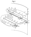
- Figure 1 shows part of a vertical column 1 having a wall 2 wherein two trays 4, 5 according the present invention are horizontally arranged.
- Both the upper tray 4 and the lower tray 5 are basically formed of a tray plate 6, 6' having top surfaces 7,7' and bottom surfaces 8,8', which tray plate is adapted so that it can be mounted to the column wall 2.
- Corresponding parts on the trays 4 and 5 are indicated by the same reference numeral, and are primed for parts on tray 5.
- openings 10, 10' are arranged in which downcomers 11, 11' are mounted.
- FIG 1 shows only portions of the trays 4,5.
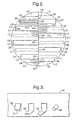
- a particular example for the arrangement of a plurality of downcomers is shown in the top view on the tray 5 in Figure 2 , wherein the downcomers are only indicated by their inlet openings 10' for the sake of clarity.
- Tray 5 is provided with a supporting beam 13' along a diametrical line dividing the tray in two sections 14',15'.
- Such a supporting beam is preferably present in trays having a large diameter, such as above 2 meters. Smaller diameter trays can be manufactured with or without a supporting beam.
- Each tray section 14,15;14',15' is provided with a plurality of parallel downcomers 11,16;11',16'.
- Each downcomer 11;11' is substantially rectangular having two elongated sidewalls 17,18;17',18' along its length and two smaller end walls 19,21;19',21' along its width.
- Preferably 1-10 rectangular shaped parallel downcomers are present in one tray section.
- one or more segmental downcomers 16;16' may be present on a tray section 14,15;14',15' where the diametrical line meets the column wall.
- the downcomers 11' extend perpendicular in horizontal direction from the supporting beam 13' to the circumferential of the tray 5.
- Downcomer end walls 19' of downcomers 11' in both tray sections 14',15' meet the supporting beam 13' in an alternating manner so that a staggered arrangement of downcomers is formed as shown.
- the opposite end walls 21' nearest the column wall 2 can be parallel to ends 19' as shown.
- the end walls 21' can also follow the circumferential of the tray (column wall), in for example a straight or curved line, in order to optimise downcomer opening area, and it shall be clear that such a downcomer is a rectangular downcomer as it still has a substantially rectangular inlet opening.
- the rectangular downcomer 10 on the upper tray 4 is shown in Figure 1 symmetrically between the rectangular downcomer 10' and the segmental downcomer 16' on the lower tray 5.
- the overall flow direction of liquid over the tray plates is perpendicular to the length of the downcomers.
- the horizontal distance between the lower end of a sidewall of a downcomer (equivalent to a longitudinal side of a bottom plate 30) on the upper tray and the nearest upper end of a sidewall on the lower tray (longitudinal side of the nearest inlet opening) is normally at least 200 mm, preferably at least 250 mm to allow for sufficient flow path length of liquid on the lower tray.
- the entire area of the tray plate 6' outside of the downcomers 11',16' on tray 5 is perforated with openings 25' (shown in the Figures only on part of the tray for the sake of clarity) and forms bubble area, including in particular the area vertically directly below the downcomer outlets of the downcomers of the upper tray 4.
- the bubble area therefore serves as liquid receiving area at the same time.
- the entire area outside the downcomers 11,16 on tray 4 preferably forms bubble area.
- the downcomers on the trays as shown in Figure 1 are provided with an inlet weir 28;28'.
- An inlet weir is a device positioned on or about on the boundary of the bubble area and the downcomer inlet opening, which ensures that a certain height of liquid is present on the upper surface of the bubble area.
- Figure 1 shows downcomers that are sloped, meaning that the downwardly directed downcomer sidewalls 17,18;17',18' are inclined towards each other in downward direction.
- Conventional sloped downcomers are e.g. discussed the general textbook “ Distillation Operation” by Henry Z. Kister, McGraw-Hill Inc, 1990, pages 173-175 , and commonly the ratio of the cross-sectional area of the inlet opening at tray level to the cross-sectional area at the bottom of a sloped downcomer is between 1.5 and 2.0 and typically 1.7.
- the present invention is not limited to the use with downcomers of such ratio of cross sections.
- the downcomers can also e.g. have vertical side walls.
- the downcomer sidewalls may be of any shape, for example having a vertical top part combined with a sloped lower part.
- a sloped or inclined sidewall suitably forms an angle of 45 degrees or less with the vertical.
- the sidewalls 17, 18 ; 17', 18' of the downcomers 11;11' are provided with liquid outlet openings 31;31'.
- the liquid outlet openings 31;31' are preferably arranged near the lower end of the sidewall 17,18, below the level of liquid which is formed in the downcomer 11 during normal operation such that the liquid outlets are sealed by the liquid against inflow of gas, vapour or froth.
- Figure 1 shows a single row of rectangular openings 31, which are manufactured by cutting or punching the sidewall along three sides of a rectangle.
- the upper side of each rectangle is not cut, and the cutout part is bent outwardly by an angle of less then 90 degrees with the sidewall, so that integrally formed guiding lips 32 are formed as shown.
- the lips serve as liquid guiding means. Without the guiding lips 32, the liquid would initially eject from the openings 31 as a stream forming an angle of 90 degrees with the sidewall, so would have a relatively large horizontal velocity component, which can result in liquid being received on the lower tray too close to the nearest downcomer inlet opening.
- the lips 32 push the ejecting liquid somewhat downwards, and in this way the area on the lower tray that receives liquid can be adjusted by adjusting the angle between the guiding lip and the sidewall.
- the guiding means 32 is adjusted such that liquid during normal operation is not received closer to the downcomer inlet opening on the lower tray than at least 100 mm, preferably at least 150 mm, most preferably at least 200 mm (measured in the perpendicular direction to the length of the downcomer which is in the overall flow direction on the tray plates), in order to provide for a sufficiently long flow path of liquid on the lower tray.
- Guiding lips are suitably also arranged on the outlet openings in the sidewall of segmental downcomers, as shown at reference numeral 33' for segmental downcomer 16'.
- the horizontal bottom plate of downcomer can also be provided with outlet openings.
- These bottom outlet openings can be e.g. slits 38 as shown in Figure 1 , but other shapes are also possible such as circular openings or slits parallel to the sidewalls of the downcomer.
- the distribution of liquid over the receiving area on the lower tray can be further optimised, so that a relatively even distribution is achieved.
- the lower end of a segmental downcomer can be provided with further liquid outlets 39'.
- FIG 3 shows schematically different embodiments of openings with guiding means in a sidewall 40 of a downcomer. Rectangular opening 31 and liquid lip 32 are the same as already discussed with reference to Figure 1 .
- the guiding lips can be attached to the lower end of the opening, as shown at reference numeral 42.
- Such liquid guiding lips 42 serve to distribute the liquid over a larger area on the tray below than without the lips, depending on the angle they form with the sidewall.
- Such guiding lips 42 opened from below form an extra barrier to prevent vapour or gas from flowing into downcomer through the liquid outlet openings.
- Guiding lips 42 can be manufactured in essentially the same way as guiding lips 32, e.g. by punching or cutting and bending.
- Liquid exiting the downcomer typically has an exit velocity ranging from 0.5 m/s to 1.5 m/s.
- the bottom plate of the truncated downcomer is typically 100 mm wide (measured perpendicular to the elongated sidewalls), and typically arranged 50-200 mm, in particular 100-200 mm above the level of the lower tray. Over this distance the liquid can distribute more or less evenly over the rectangular shaped volume directly underneath the bottom plate. Assume that the slots account for 50% of the area of bottom plate.
- the liquid impacts on to the lower tray in the 100 mm wide area directly underneath the downcomer at an impact velocity which is a factor 2 lower than the exit velocity; in this case the impact velocity is typically 0.25 m/s-0.75 m/s.
- the impact velocity is typically 0.25 m/s-0.75 m/s.
- the liquid receiving area on the lower tray can be increased by a factor of up to 5 or more. If, for example, the openings and guiding means are arranged such that liquid is evenly distributed over an area of a width of 300 mm (instead of 100 mm), the impact velocity is reduced to typically 0.08 m/s-0.25 m/s. Such impact velocities do not normally lead to liquid penetration problems when perforations are arranged on the receiving tray.
- tray layouts including rectangular downcomers are described for example in US-A-5 702 647 , US-A-5 382 390 , GB-A-1 416 731 and US-A-3 410 540 .
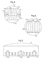
- Figure 4 illustrates a top view of the normal flow pattern 105 on a conventional cross-flow tray 104 in a column 101, wherein liquid is received from the liquid outlet of a conventional truncated downcomer 111 of an upper tray, and flows over the tray to the inlet of the downcomer 112 through which it is removed to a still lower tray.
- This type of flow pattern leads to liquid recirculation (back mixing) in areas 115 and this can lead to lower tray efficiency. This problem is discussed e.g. in USA patent specification No.
- Openings with liquid guiding means are provided in the sidewall of the downcomer, such that the liquid is deflected in the horizontal plane, so that the liquid at each outlet is guided to flow in an optimum direction on to and over the tray.
- a schematic arrangement of a row of slots with guiding lips in the sidewall of the segmental downcomer 211 according to the invention is shown in Figure 5 .
- the guiding lips 236 are arranged such that the liquid exiting from the slots 240 close to the column wall 2 is guided along the wall 2.
- the slots 242 in the centre suitably guide the liquid along a diameter to the opposite side of the tray, and therefore no guiding means are needed in the centre, or the lips can be arranged by bending to an angle larger than 90 degrees as indicated at 245.
- the angle of the guiding lips with the sidewall can for example be 30-45 degrees at the sides close to the column wall, and the angle suitably gradually increases more towards the centre.
- the downcomers of a tray according to the present invention are truncated downcomers.
- US-A-4 550 000 describes an example of a rectangular truncated downcomer.
- a truncated downcomer is characterised in that, when in use, its liquid discharge openings are not submerged in the liquid level which is present just on the bubble area of the lower tray. In other words, no liquid seal is present between the liquid discharge opening of the downcomer and the space above a consecutive lower tray.
- Truncated downcomers preferably extend to between 30 and 90% and preferably between 50 and 75% of the tray spacing below a tray. Furthermore the liquid discharge openings of truncated downcomers will be positioned at a higher vertical position than the top end of an optional weir on the lower tray.
- Tray spacing is defined as the distance between two consecutive gas-liquid contacting trays in a column. Typical tray spacing is between 0.2 and 1 m.
- the downcomers can be provided with an inlet weir along their inlet opening.
- the inlet weir can be disposed vertically or inclined.
- the inlet weir may run along said entire boundary or may optionally be interrupted.
- the inlet weir may be solid.
- Preferably openings are present in the inlet weir.
- the downcomer wall and weir can be arranged in one plane and advantageously made from one metal plate.
- the height of the inlet weir is preferably less than 50% of the distance between the lowest liquid discharge openings of the next higher tray and the liquid receiving area below said openings. More preferably the vertical height is between 0.01 and 0.05 m.
- a rectangular downcomer is preferably provided with a rectangular shaped anti-jump baffle, vertically positioned along the longitudinal centre in the opening of the downcomer.
- This anti-jump baffle plate is suitably supported from both sides by supports, which are fixed to the inside of the downcomer walls.
Landscapes
- Chemical & Material Sciences (AREA)
- Chemical Kinetics & Catalysis (AREA)
- Engineering & Computer Science (AREA)
- Analytical Chemistry (AREA)
- General Chemical & Material Sciences (AREA)
- Oil, Petroleum & Natural Gas (AREA)
- Vaporization, Distillation, Condensation, Sublimation, And Cold Traps (AREA)
- Gas Separation By Absorption (AREA)
- Contacts (AREA)
- Physical Or Chemical Processes And Apparatus (AREA)
Claims (13)
- Gas-Flüssigkeits-Kontaktierboden, der sich zur horizontalen Befestigung in einer normalerweise vertikalen Säule für den Gegenstromkontakt von Gas und Flüssigkeit eignet, wobei der Boden aufweist:- eine Bodenplatte mit einer Oberseite und einer Unterseite, in welcher Bodenplatte eine Ablaufrinnen-Einlaßöffnung angeordnet ist; und- eine Ablaufrinne zur Führung der Flüssigkeit von der Oberseite der Bodenplatte zu einer Ablaufrinnen-Auslaßöffnung unterhalb der Bodenplatte, wobei die Ablaufrinne eine Seitenwand hat, die sich von der Ablaufrinnen-Einlaßöffnung nach unten erstreckt, in welcher Ablaufrinnen-Seitenwand die Flüssigkeitsauslaßöffnung angeordnet ist, und wobei die Flüssigkeitsauslaßöffnung mit einem Flüssigkeits-Führungsmittel versehen ist.
- Gas-Flüssigkeits-Kontaktierboden nach Anspruch 1, bei welchem das Führungsmittel eine Führungslippe oder eine Führungstülle ist.
- Gas-Flüssigkeits-Kontaktierboden nach Anspruch 1 oder 2, bei welcher das Führungsmittel einstückig mit der Ablaufrinnen-Seitenwand geformt ist.
- Gas-Flüssigkeits-Kontaktierboden nach einem der Ansprüche 1-3, bei welchem das Flüssigkeits-Führungsmittel so angeordnet ist, daß es die Größe der Vertikalgeschwindigkeitskomponente der Flüssigkeit beeinflusst, die während des Normalbetriebes durch die Flüssigkeitsauslaßöffnung austritt.
- Gas-Flüssigkeits-Kontaktierboden nach einem der Ansprüche 1-4, bei welchem das Flüssigkeits-Führungsmittel so ausgebildet ist, daß es die Richtung der horizontalen Geschwindigkeitskomponente der Flüssigkeit beeinflusst, die während des Normalbetriebes durch die Flüssigkeitsauslaßöffnung austritt.
- Gas-Flüssigkeits-Kontaktierboden nach einem der Ansprüche 1-5, bei welchem die Ablaufrinne aus der Gruppe gewählt wird, die eine geneigte Ablaufrinne, eine sehr geneigte Ablaufrinne, eine Ablaufrinne mit vertikalen Seitenwänden und eine Ablaufrinne mit teilweise vertikalen und teilweise geneigten Seitenwänden umfaßt.
- Gas-Flüssigkeits-Kontaktierboden nach einem der Ansprüche 1-6, bei welchem eine Vielzahl von Flüssigkeitsauslaßöffnungen in der Seitenwand angeordnet ist, wobei zumindest ein Teil dieser Vielzahl mit Flüssigkeits-Führungsmitteln ausgestattet ist.
- Gas-Flüssigkeits-Kontaktierboden nach einem der Ansprüche 1-7, bei welchem die Ablaufrinne eine im wesentlichen horizontale Bodenplatte hat, und bei welcher eine weitere Flüssigkeitsauslaßöffnung in der Bodenplatte vorgesehen ist.
- Gas-Flüssigkeits-Kontaktierboden nach einem der Ansprüche 1-8, bei welchem die Ablaufrinne eine rechteckige Ablaufrinne ist.
- Gas-Flüssigkeits-Kontaktierboden nach einem der Ansprüche 1-9, bei welchem der Boden einen oberen Boden bildet, der oberhalb eines unteren Bodens angeordnet ist, welcher eine Bodenplatte hat, die mit einer Ablaufrinne versehen ist, die sich allgemein parallel zur Seitenwand der Ablaufrinne des oberen Bodens erstreckt und seitlich bezüglich der Ablaufrinne auf dem oberen Boden fortgesetzt ist, und bei welchem das Flüssigkeits-Führungsmittel so eingestellt ist, daß die Flüssigkeit während des Normalbetriebes nicht näher an der Ablaufrinnen-Einlaßöffnung auf der unteren Bodenplatte als zumindest 100 mm, vorzugsweise zumindest 150 mm, noch bevorzugter zumindest 200 mm empfangen wird.
- Gas-Flüssigkeits-Kontaktierboden nach Anspruch 9, bei welcher der Boden einen oberen Boden bildet, der oberhalb eines unteren Bodens angeordnet ist, welcher eine Bodenplatte hat, die mit zumindest zwei Ablaufrinnen ausgestattet ist, die sich allgemein parallel zu den Seitenwänden der rechteckigen Ablaufrinne des oberen Bodens erstrecken, und bei welchem die Ablaufrinne des oberen Bodens zwischen, vorzugsweise symmetrisch zwischen zwei Ablaufrinnen an dem unteren Boden angeordnet ist.
- Gas-Flüssigkeits-Kontaktierboden nach Anspruch 11, bei welchem das Flüssigkeits-Führungsmittel so eingestellt ist, daß die Flüssigkeit während des Normalbetriebes nicht näher an der Ablaufrinnen-Einlaßöffnung auf dem unteren Boden als zumindest 100 mm, vorzugsweise zumindest 150 mm, noch bevorzugter zumindest 200 mm empfangen wird.
- Gas-Flüssigkeits-Kontaktierboden nach einem der Ansprüche 1-8, bei welchem die Ablaufrinne eine Ablaufrinne aus Segmenten ist, und bei welchem eine Vielzahl von Flüssigkeitsauslaßöffnungen mit Führungsmitteln in einer Reihe angeordnet sind, um die Flüssigkeit so zu führen, daß während des Normalbetriebes ein Propfenströmungsmuster auf einem unteren Aufnahmeboden erzeugt wird.
Priority Applications (2)
| Application Number | Priority Date | Filing Date | Title |
|---|---|---|---|
| EP04766330A EP1663453B1 (de) | 2003-08-13 | 2004-07-27 | Gas-flüssigkeitkontaktboden |
| ES04766330T ES2305830T3 (es) | 2003-08-13 | 2004-07-27 | Bandeja de contacto gas-liquido. |
Applications Claiming Priority (3)
| Application Number | Priority Date | Filing Date | Title |
|---|---|---|---|
| EP03077534 | 2003-08-13 | ||
| EP04766330A EP1663453B1 (de) | 2003-08-13 | 2004-07-27 | Gas-flüssigkeitkontaktboden |
| PCT/EP2004/051620 WO2005016493A1 (en) | 2003-08-13 | 2004-07-27 | Gas-liquid contacting tray |
Publications (2)
| Publication Number | Publication Date |
|---|---|
| EP1663453A1 EP1663453A1 (de) | 2006-06-07 |
| EP1663453B1 true EP1663453B1 (de) | 2008-04-23 |
Family
ID=34178530
Family Applications (1)
| Application Number | Title | Priority Date | Filing Date |
|---|---|---|---|
| EP04766330A Expired - Lifetime EP1663453B1 (de) | 2003-08-13 | 2004-07-27 | Gas-flüssigkeitkontaktboden |
Country Status (8)
| Country | Link |
|---|---|
| US (1) | US7232115B2 (de) |
| EP (1) | EP1663453B1 (de) |
| AT (1) | ATE392940T1 (de) |
| CA (1) | CA2534878A1 (de) |
| DE (1) | DE602004013344T2 (de) |
| ES (1) | ES2305830T3 (de) |
| WO (1) | WO2005016493A1 (de) |
| ZA (1) | ZA200601000B (de) |
Families Citing this family (14)
| Publication number | Priority date | Publication date | Assignee | Title |
|---|---|---|---|---|
| SE528996C2 (sv) * | 2005-04-29 | 2007-04-03 | Alfa Laval Corp Ab | Förfarande för deodorisering, en botten för pluggflöde, en kolonn, en anläggning och användning av en deodoriseringsanläggning |
| US7204477B2 (en) * | 2005-06-01 | 2007-04-17 | Uop Llc | Parallel flow fractionation tray |
| EP2108421B1 (de) * | 2008-04-11 | 2018-01-24 | Sulzer Chemtech AG | Mehrfach-Downcomer Kolonnenboden |
| US8074972B2 (en) * | 2008-06-18 | 2011-12-13 | Uop Llc | Device for gas-liquid contacting |
| US8246016B2 (en) * | 2008-07-18 | 2012-08-21 | Uop Llc | Downcomer for a gas-liquid contacting device |
| US8052126B2 (en) * | 2008-12-31 | 2011-11-08 | Uop Llc | Liquid distribution in co-current contacting apparatuses |
| EP2371541B1 (de) * | 2010-03-30 | 2013-06-05 | Agfa Graphics N.V. | System und Verfahren zur digitalen Erzeugung einer Druckvorlage unter Verwendung einer Einheit mit mehreren Druckköpfen |
| USD650466S1 (en) * | 2010-04-12 | 2011-12-13 | Koch-Glitsch, Lp | Bubble promoter for a cross-flow tray |
| FR3006599B1 (fr) * | 2013-06-10 | 2015-05-29 | IFP Energies Nouvelles | Plateau distributeur pour colonne de contact gaz/liquide avec systeme de distribution secondaire |
| CN105964126A (zh) * | 2016-07-04 | 2016-09-28 | 钱诚 | 一种折扇型脱硫吸收塔托盘 |
| CN111495313B (zh) * | 2020-06-05 | 2025-06-03 | 中国海洋石油集团有限公司 | 一种复合塔盘以及包括该复合塔盘的板式塔 |
| TWI781902B (zh) * | 2021-09-23 | 2022-10-21 | 大陸商北京澤華化學工程有限公司 | 多鼓泡區塔板以及相應的板式塔 |
| CN115463443B (zh) * | 2022-10-31 | 2023-10-20 | 宿州市东凯医药科技有限公司 | 一种用于制药的精馏系统 |
| CN116492705B (zh) * | 2023-06-12 | 2024-03-19 | 安徽益沣石化有限公司 | 一种mtbe原料精馏脱硫装置及其方法 |
Family Cites Families (26)
| Publication number | Priority date | Publication date | Assignee | Title |
|---|---|---|---|---|
| US1770221A (en) * | 1927-05-13 | 1930-07-08 | Standard Oil Co | Bubble tower |
| US3410540A (en) * | 1964-11-09 | 1968-11-12 | Union Carbide Corp | Vapor-liquid contact system and method |
| US3729179A (en) * | 1970-09-23 | 1973-04-24 | Fractionation Res Inc | Apparatus for liquid and vapor or gas mass transfer |
| GB1422132A (en) * | 1972-02-07 | 1976-01-21 | Shell Int Research | Liquid discharge member for liquid-vapour contacting tray |
| BE794705A (nl) | 1972-02-07 | 1973-07-30 | Shell Int Research | Kolom voorzien van vloeistof-damp contactschotels |
| CA1110538A (en) * | 1977-08-16 | 1981-10-13 | Walter Bruckert | Outlet means for vapor liquid contacting tray |
| US4159291A (en) * | 1977-08-16 | 1979-06-26 | Union Carbide Corporation | Outlet means for vapor-liquid contacting tray |
| CA1211364A (en) * | 1982-04-15 | 1986-09-16 | Jeremy B. Bentham | Apparatus for contacting a liquid with a gas |
| US4956127A (en) * | 1989-03-08 | 1990-09-11 | Glitsch, Inc. | Downcomer-tray assembly and method |
| US5366666A (en) * | 1990-05-25 | 1994-11-22 | Uop | Multiple downcomer fractionation tray having packing between downcomers |
| US5382390A (en) * | 1990-09-10 | 1995-01-17 | Uop | Multiple-downcomer fractionation tray with vapor directing slots and extended downcomer baffles |
| US5098615A (en) * | 1990-10-19 | 1992-03-24 | Uop | Multiple-downcomer contacting tray with fluid directing baffles |
| CA2035701C (en) * | 1991-02-05 | 1999-01-19 | Karl T. Chuang | Active liquid distributor containing, packed column |
| US5407605A (en) * | 1993-12-16 | 1995-04-18 | Uop | Fractionation tray with side discharging triangular downcomers |
| US5632935A (en) * | 1994-04-28 | 1997-05-27 | Koch Engineering Company, Inc. | Vapor-liquid contact tray and downcomer assembly and method employing same |
| AU694850B2 (en) * | 1995-03-31 | 1998-07-30 | Koch (Cyprus) Limited | Multi-downcomer high performance tray assembly |
| US5683493A (en) * | 1996-07-19 | 1997-11-04 | Stober; Berne K. | Packing for separation columns and process of use |
| WO1999011347A1 (en) * | 1997-09-05 | 1999-03-11 | Koch-Glitsch,Inc. | Downcomers for vapor-liquid contact trays |
| ATE291948T1 (de) * | 1998-11-30 | 2005-04-15 | Sulzer Chemtech Ag | Flüssigkeitsverteiler für packungskolonnen |
| RU2241514C2 (ru) * | 2000-02-16 | 2004-12-10 | Шелл Интернэшнл Рисерч Маатсхаппий Б.В. | Тарелка для контактирования газа с жидкостью |
| US6460834B2 (en) * | 2000-02-16 | 2002-10-08 | Shell Oil Company | Gas/liquid contact tray |
| US6863267B2 (en) | 2000-02-16 | 2005-03-08 | Shell Oil Company | Gas-liquid contacting tray |
| ATE401114T1 (de) * | 2000-05-08 | 2008-08-15 | Sulzer Chemtech Ag | Kolonne mit einem boden zwischen füllkörperabschnitten |
| US6722639B2 (en) * | 2001-04-10 | 2004-04-20 | Koch-Glitsch, Lp | Liquid distributor in mass transfer column and method of installation and use |
| DE50214608D1 (de) * | 2001-12-05 | 2010-10-07 | Sulzer Chemtech Ag | Bodenkolonne |
| US20030183957A1 (en) * | 2002-03-28 | 2003-10-02 | Nader Zarabi | Downcomer vapor/liquid flood windows and hinged downcomer weir for reducing tray tower floodings |
-
2004
- 2004-07-27 DE DE602004013344T patent/DE602004013344T2/de not_active Expired - Fee Related
- 2004-07-27 AT AT04766330T patent/ATE392940T1/de not_active IP Right Cessation
- 2004-07-27 EP EP04766330A patent/EP1663453B1/de not_active Expired - Lifetime
- 2004-07-27 CA CA002534878A patent/CA2534878A1/en not_active Abandoned
- 2004-07-27 WO PCT/EP2004/051620 patent/WO2005016493A1/en not_active Ceased
- 2004-07-27 ES ES04766330T patent/ES2305830T3/es not_active Expired - Lifetime
- 2004-08-13 US US10/918,557 patent/US7232115B2/en not_active Expired - Lifetime
-
2006
- 2006-02-03 ZA ZA200601000A patent/ZA200601000B/en unknown
Also Published As
| Publication number | Publication date |
|---|---|
| CA2534878A1 (en) | 2005-02-24 |
| US7232115B2 (en) | 2007-06-19 |
| DE602004013344T2 (de) | 2009-05-28 |
| WO2005016493A1 (en) | 2005-02-24 |
| ES2305830T3 (es) | 2008-11-01 |
| US20050046051A1 (en) | 2005-03-03 |
| EP1663453A1 (de) | 2006-06-07 |
| ZA200601000B (en) | 2007-04-25 |
| DE602004013344D1 (de) | 2008-06-05 |
| ATE392940T1 (de) | 2008-05-15 |
Similar Documents
| Publication | Publication Date | Title |
|---|---|---|
| US6224043B1 (en) | Downcomers for vapor-liquid contact trays | |
| EP1663453B1 (de) | Gas-flüssigkeitkontaktboden | |
| US6902154B2 (en) | Gas-liquid contact tray having multiple downcomers | |
| EP1881865B1 (de) | Fluidezulaufvorrichtung und anwendung | |
| US6494440B2 (en) | Gas-liquid contacting tray | |
| AU2001242403A1 (en) | Gas-liquid contacting tray | |
| US6460833B2 (en) | Gas-liquid contacting column | |
| WO2016025403A1 (en) | Method and system for orifice control of valve pressure drop | |
| US20080150171A1 (en) | Gas-liquid contact apparatus | |
| US6863267B2 (en) | Gas-liquid contacting tray | |
| US20030011084A1 (en) | Gas-liquid tray | |
| CA3196509A1 (en) | A multistage liquid distributor for a separation device comprising a dual-trough pre-distributor | |
| AU1451799A (en) | High-capacity vapor/liquid contacting device |
Legal Events
| Date | Code | Title | Description |
|---|---|---|---|
| PUAI | Public reference made under article 153(3) epc to a published international application that has entered the european phase |
Free format text: ORIGINAL CODE: 0009012 |
|
| 17P | Request for examination filed |
Effective date: 20060309 |
|
| AK | Designated contracting states |
Kind code of ref document: A1 Designated state(s): AT BE BG CH CY CZ DE DK EE ES FI FR GB GR HU IE IT LI LU MC NL PL PT RO SE SI SK TR |
|
| DAX | Request for extension of the european patent (deleted) | ||
| RIN1 | Information on inventor provided before grant (corrected) |
Inventor name: SASTRY, ASHEESH VISWANATHA |
|
| GRAP | Despatch of communication of intention to grant a patent |
Free format text: ORIGINAL CODE: EPIDOSNIGR1 |
|
| GRAS | Grant fee paid |
Free format text: ORIGINAL CODE: EPIDOSNIGR3 |
|
| GRAA | (expected) grant |
Free format text: ORIGINAL CODE: 0009210 |
|
| AK | Designated contracting states |
Kind code of ref document: B1 Designated state(s): AT BE BG CH CY CZ DE DK EE ES FI FR GB GR HU IE IT LI LU MC NL PL PT RO SE SI SK TR |
|
| REG | Reference to a national code |
Ref country code: GB Ref legal event code: FG4D |
|
| REG | Reference to a national code |
Ref country code: CH Ref legal event code: EP |
|
| REF | Corresponds to: |
Ref document number: 602004013344 Country of ref document: DE Date of ref document: 20080605 Kind code of ref document: P |
|
| REG | Reference to a national code |
Ref country code: IE Ref legal event code: FG4D Free format text: LANGUAGE OF EP DOCUMENT: FRENCH |
|
| PG25 | Lapsed in a contracting state [announced via postgrant information from national office to epo] |
Ref country code: SI Free format text: LAPSE BECAUSE OF FAILURE TO SUBMIT A TRANSLATION OF THE DESCRIPTION OR TO PAY THE FEE WITHIN THE PRESCRIBED TIME-LIMIT Effective date: 20080423 |
|
| PGFP | Annual fee paid to national office [announced via postgrant information from national office to epo] |
Ref country code: BE Payment date: 20080630 Year of fee payment: 5 |
|
| PG25 | Lapsed in a contracting state [announced via postgrant information from national office to epo] |
Ref country code: FI Free format text: LAPSE BECAUSE OF FAILURE TO SUBMIT A TRANSLATION OF THE DESCRIPTION OR TO PAY THE FEE WITHIN THE PRESCRIBED TIME-LIMIT Effective date: 20080423 Ref country code: PT Free format text: LAPSE BECAUSE OF FAILURE TO SUBMIT A TRANSLATION OF THE DESCRIPTION OR TO PAY THE FEE WITHIN THE PRESCRIBED TIME-LIMIT Effective date: 20080923 Ref country code: BG Free format text: LAPSE BECAUSE OF FAILURE TO SUBMIT A TRANSLATION OF THE DESCRIPTION OR TO PAY THE FEE WITHIN THE PRESCRIBED TIME-LIMIT Effective date: 20080723 |
|
| PGFP | Annual fee paid to national office [announced via postgrant information from national office to epo] |
Ref country code: DE Payment date: 20080715 Year of fee payment: 5 Ref country code: ES Payment date: 20080729 Year of fee payment: 5 |
|
| REG | Reference to a national code |
Ref country code: ES Ref legal event code: FG2A Ref document number: 2305830 Country of ref document: ES Kind code of ref document: T3 |
|
| PG25 | Lapsed in a contracting state [announced via postgrant information from national office to epo] |
Ref country code: PL Free format text: LAPSE BECAUSE OF FAILURE TO SUBMIT A TRANSLATION OF THE DESCRIPTION OR TO PAY THE FEE WITHIN THE PRESCRIBED TIME-LIMIT Effective date: 20080423 Ref country code: AT Free format text: LAPSE BECAUSE OF FAILURE TO SUBMIT A TRANSLATION OF THE DESCRIPTION OR TO PAY THE FEE WITHIN THE PRESCRIBED TIME-LIMIT Effective date: 20080423 |
|
| PGFP | Annual fee paid to national office [announced via postgrant information from national office to epo] |
Ref country code: IT Payment date: 20080623 Year of fee payment: 5 Ref country code: NL Payment date: 20080708 Year of fee payment: 5 |
|
| ET | Fr: translation filed | ||
| PGFP | Annual fee paid to national office [announced via postgrant information from national office to epo] |
Ref country code: GB Payment date: 20080623 Year of fee payment: 5 |
|
| PG25 | Lapsed in a contracting state [announced via postgrant information from national office to epo] |
Ref country code: SE Free format text: LAPSE BECAUSE OF FAILURE TO SUBMIT A TRANSLATION OF THE DESCRIPTION OR TO PAY THE FEE WITHIN THE PRESCRIBED TIME-LIMIT Effective date: 20080723 Ref country code: DK Free format text: LAPSE BECAUSE OF FAILURE TO SUBMIT A TRANSLATION OF THE DESCRIPTION OR TO PAY THE FEE WITHIN THE PRESCRIBED TIME-LIMIT Effective date: 20080423 Ref country code: CZ Free format text: LAPSE BECAUSE OF FAILURE TO SUBMIT A TRANSLATION OF THE DESCRIPTION OR TO PAY THE FEE WITHIN THE PRESCRIBED TIME-LIMIT Effective date: 20080423 |
|
| PG25 | Lapsed in a contracting state [announced via postgrant information from national office to epo] |
Ref country code: RO Free format text: LAPSE BECAUSE OF FAILURE TO SUBMIT A TRANSLATION OF THE DESCRIPTION OR TO PAY THE FEE WITHIN THE PRESCRIBED TIME-LIMIT Effective date: 20080423 Ref country code: SK Free format text: LAPSE BECAUSE OF FAILURE TO SUBMIT A TRANSLATION OF THE DESCRIPTION OR TO PAY THE FEE WITHIN THE PRESCRIBED TIME-LIMIT Effective date: 20080423 |
|
| PLBE | No opposition filed within time limit |
Free format text: ORIGINAL CODE: 0009261 |
|
| REG | Reference to a national code |
Ref country code: CH Ref legal event code: PL |
|
| STAA | Information on the status of an ep patent application or granted ep patent |
Free format text: STATUS: NO OPPOSITION FILED WITHIN TIME LIMIT |
|
| PG25 | Lapsed in a contracting state [announced via postgrant information from national office to epo] |
Ref country code: MC Free format text: LAPSE BECAUSE OF NON-PAYMENT OF DUE FEES Effective date: 20080731 |
|
| 26N | No opposition filed |
Effective date: 20090126 |
|
| REG | Reference to a national code |
Ref country code: IE Ref legal event code: MM4A |
|
| PG25 | Lapsed in a contracting state [announced via postgrant information from national office to epo] |
Ref country code: EE Free format text: LAPSE BECAUSE OF FAILURE TO SUBMIT A TRANSLATION OF THE DESCRIPTION OR TO PAY THE FEE WITHIN THE PRESCRIBED TIME-LIMIT Effective date: 20080423 |
|
| PG25 | Lapsed in a contracting state [announced via postgrant information from national office to epo] |
Ref country code: LI Free format text: LAPSE BECAUSE OF NON-PAYMENT OF DUE FEES Effective date: 20080731 Ref country code: CH Free format text: LAPSE BECAUSE OF NON-PAYMENT OF DUE FEES Effective date: 20080731 |
|
| PG25 | Lapsed in a contracting state [announced via postgrant information from national office to epo] |
Ref country code: IE Free format text: LAPSE BECAUSE OF NON-PAYMENT OF DUE FEES Effective date: 20080727 |
|
| BERE | Be: lapsed |
Owner name: SHELL INTERNATIONALE RESEARCH MAATSCHAPPIJ B.V. Effective date: 20090731 |
|
| GBPC | Gb: european patent ceased through non-payment of renewal fee |
Effective date: 20090727 |
|
| NLV4 | Nl: lapsed or anulled due to non-payment of the annual fee |
Effective date: 20100201 |
|
| REG | Reference to a national code |
Ref country code: FR Ref legal event code: ST Effective date: 20100331 |
|
| PG25 | Lapsed in a contracting state [announced via postgrant information from national office to epo] |
Ref country code: FR Free format text: LAPSE BECAUSE OF NON-PAYMENT OF DUE FEES Effective date: 20090731 |
|
| PGFP | Annual fee paid to national office [announced via postgrant information from national office to epo] |
Ref country code: FR Payment date: 20080520 Year of fee payment: 5 |
|
| PG25 | Lapsed in a contracting state [announced via postgrant information from national office to epo] |
Ref country code: GB Free format text: LAPSE BECAUSE OF NON-PAYMENT OF DUE FEES Effective date: 20090727 |
|
| PG25 | Lapsed in a contracting state [announced via postgrant information from national office to epo] |
Ref country code: DE Free format text: LAPSE BECAUSE OF NON-PAYMENT OF DUE FEES Effective date: 20100202 Ref country code: BE Free format text: LAPSE BECAUSE OF NON-PAYMENT OF DUE FEES Effective date: 20090731 |
|
| PG25 | Lapsed in a contracting state [announced via postgrant information from national office to epo] |
Ref country code: LU Free format text: LAPSE BECAUSE OF NON-PAYMENT OF DUE FEES Effective date: 20080727 Ref country code: CY Free format text: LAPSE BECAUSE OF FAILURE TO SUBMIT A TRANSLATION OF THE DESCRIPTION OR TO PAY THE FEE WITHIN THE PRESCRIBED TIME-LIMIT Effective date: 20080423 Ref country code: HU Free format text: LAPSE BECAUSE OF FAILURE TO SUBMIT A TRANSLATION OF THE DESCRIPTION OR TO PAY THE FEE WITHIN THE PRESCRIBED TIME-LIMIT Effective date: 20081024 |
|
| PG25 | Lapsed in a contracting state [announced via postgrant information from national office to epo] |
Ref country code: TR Free format text: LAPSE BECAUSE OF FAILURE TO SUBMIT A TRANSLATION OF THE DESCRIPTION OR TO PAY THE FEE WITHIN THE PRESCRIBED TIME-LIMIT Effective date: 20080423 |
|
| REG | Reference to a national code |
Ref country code: ES Ref legal event code: FD2A Effective date: 20090728 |
|
| PG25 | Lapsed in a contracting state [announced via postgrant information from national office to epo] |
Ref country code: ES Free format text: LAPSE BECAUSE OF NON-PAYMENT OF DUE FEES Effective date: 20090728 Ref country code: GR Free format text: LAPSE BECAUSE OF FAILURE TO SUBMIT A TRANSLATION OF THE DESCRIPTION OR TO PAY THE FEE WITHIN THE PRESCRIBED TIME-LIMIT Effective date: 20080724 |
|
| PG25 | Lapsed in a contracting state [announced via postgrant information from national office to epo] |
Ref country code: IT Free format text: LAPSE BECAUSE OF NON-PAYMENT OF DUE FEES Effective date: 20090727 |
|
| PG25 | Lapsed in a contracting state [announced via postgrant information from national office to epo] |
Ref country code: NL Free format text: LAPSE BECAUSE OF NON-PAYMENT OF DUE FEES Effective date: 20100201 |