EP1663008B1 - Connecteur permettant de fixer un catheter a ultrasons sur un transducteur - Google Patents
Connecteur permettant de fixer un catheter a ultrasons sur un transducteur Download PDFInfo
- Publication number
- EP1663008B1 EP1663008B1 EP03754997A EP03754997A EP1663008B1 EP 1663008 B1 EP1663008 B1 EP 1663008B1 EP 03754997 A EP03754997 A EP 03754997A EP 03754997 A EP03754997 A EP 03754997A EP 1663008 B1 EP1663008 B1 EP 1663008B1
- Authority
- EP
- European Patent Office
- Prior art keywords
- ultrasound
- nesting piece
- bore
- transmission member
- proximal
- Prior art date
- Legal status (The legal status is an assumption and is not a legal conclusion. Google has not performed a legal analysis and makes no representation as to the accuracy of the status listed.)
- Expired - Lifetime
Links
- 238000002604 ultrasonography Methods 0.000 title claims description 81
- 230000005540 biological transmission Effects 0.000 claims description 35
- 238000000034 method Methods 0.000 claims description 9
- 230000000717 retained effect Effects 0.000 claims description 6
- 230000000644 propagated effect Effects 0.000 claims description 3
- 239000000463 material Substances 0.000 description 6
- 239000002826 coolant Substances 0.000 description 5
- 239000012530 fluid Substances 0.000 description 5
- 230000006870 function Effects 0.000 description 5
- 238000002347 injection Methods 0.000 description 4
- 239000007924 injection Substances 0.000 description 4
- 210000004204 blood vessel Anatomy 0.000 description 3
- 241001465754 Metazoa Species 0.000 description 2
- 239000002872 contrast media Substances 0.000 description 2
- 238000001802 infusion Methods 0.000 description 2
- 229910001092 metal group alloy Inorganic materials 0.000 description 2
- HUHDYASLFWQVOL-WZTVWXICSA-N 3-[[2-[[3-[acetyl(methyl)amino]-2,4,6-triiodo-5-(methylcarbamoyl)benzoyl]amino]acetyl]amino]-5-(2-hydroxyethylcarbamoyl)-2,4,6-triiodobenzoic acid;(2r,3r,4r,5s)-6-(methylamino)hexane-1,2,3,4,5-pentol Chemical compound CNC[C@H](O)[C@@H](O)[C@H](O)[C@H](O)CO.CNC(=O)C1=C(I)C(N(C)C(C)=O)=C(I)C(C(=O)NCC(=O)NC=2C(=C(C(=O)NCCO)C(I)=C(C(O)=O)C=2I)I)=C1I HUHDYASLFWQVOL-WZTVWXICSA-N 0.000 description 1
- 229920001875 Ebonite Polymers 0.000 description 1
- FAPWRFPIFSIZLT-UHFFFAOYSA-M Sodium chloride Chemical compound [Na+].[Cl-] FAPWRFPIFSIZLT-UHFFFAOYSA-M 0.000 description 1
- 210000002376 aorta thoracic Anatomy 0.000 description 1
- 238000005452 bending Methods 0.000 description 1
- 239000000919 ceramic Substances 0.000 description 1
- 239000002131 composite material Substances 0.000 description 1
- 229940039231 contrast media Drugs 0.000 description 1
- 238000001816 cooling Methods 0.000 description 1
- 210000004351 coronary vessel Anatomy 0.000 description 1
- 239000013078 crystal Substances 0.000 description 1
- 230000000994 depressogenic effect Effects 0.000 description 1
- 230000000694 effects Effects 0.000 description 1
- 238000011067 equilibration Methods 0.000 description 1
- 239000000835 fiber Substances 0.000 description 1
- 238000003384 imaging method Methods 0.000 description 1
- 230000007246 mechanism Effects 0.000 description 1
- 239000002184 metal Substances 0.000 description 1
- 239000000203 mixture Substances 0.000 description 1
- 238000012986 modification Methods 0.000 description 1
- 230000004048 modification Effects 0.000 description 1
- 230000000414 obstructive effect Effects 0.000 description 1
- 238000013021 overheating Methods 0.000 description 1
- 239000004033 plastic Substances 0.000 description 1
- 229920000642 polymer Polymers 0.000 description 1
- 238000003825 pressing Methods 0.000 description 1
- 230000001737 promoting effect Effects 0.000 description 1
- 229910001285 shape-memory alloy Inorganic materials 0.000 description 1
- XZNXVSDNACTASG-RZNNTOFGSA-M sodium;3,5-diacetamido-2,4,6-triiodobenzoate;3,5-diacetamido-2,4,6-triiodobenzoic acid;(2r,3r,4r,5s)-6-(methylamino)hexane-1,2,3,4,5-pentol Chemical compound [Na+].CNC[C@H](O)[C@@H](O)[C@H](O)[C@H](O)CO.CC(=O)NC1=C(I)C(NC(C)=O)=C(I)C(C(O)=O)=C1I.CC(=O)NC1=C(I)C(NC(C)=O)=C(I)C(C([O-])=O)=C1I XZNXVSDNACTASG-RZNNTOFGSA-M 0.000 description 1
- 239000000243 solution Substances 0.000 description 1
- VIDRYROWYFWGSY-UHFFFAOYSA-N sotalol hydrochloride Chemical compound Cl.CC(C)NCC(O)C1=CC=C(NS(C)(=O)=O)C=C1 VIDRYROWYFWGSY-UHFFFAOYSA-N 0.000 description 1
- 230000001225 therapeutic effect Effects 0.000 description 1
- 210000005166 vasculature Anatomy 0.000 description 1
Images


Classifications
-
- A—HUMAN NECESSITIES
- A61—MEDICAL OR VETERINARY SCIENCE; HYGIENE
- A61B—DIAGNOSIS; SURGERY; IDENTIFICATION
- A61B17/00—Surgical instruments, devices or methods
- A61B17/22—Implements for squeezing-off ulcers or the like on inner organs of the body; Implements for scraping-out cavities of body organs, e.g. bones; for invasive removal or destruction of calculus using mechanical vibrations; for removing obstructions in blood vessels, not otherwise provided for
- A61B17/22004—Implements for squeezing-off ulcers or the like on inner organs of the body; Implements for scraping-out cavities of body organs, e.g. bones; for invasive removal or destruction of calculus using mechanical vibrations; for removing obstructions in blood vessels, not otherwise provided for using mechanical vibrations, e.g. ultrasonic shock waves
- A61B17/22012—Implements for squeezing-off ulcers or the like on inner organs of the body; Implements for scraping-out cavities of body organs, e.g. bones; for invasive removal or destruction of calculus using mechanical vibrations; for removing obstructions in blood vessels, not otherwise provided for using mechanical vibrations, e.g. ultrasonic shock waves in direct contact with, or very close to, the obstruction or concrement
-
- A—HUMAN NECESSITIES
- A61—MEDICAL OR VETERINARY SCIENCE; HYGIENE
- A61B—DIAGNOSIS; SURGERY; IDENTIFICATION
- A61B17/00—Surgical instruments, devices or methods
- A61B2017/00477—Coupling
-
- A—HUMAN NECESSITIES
- A61—MEDICAL OR VETERINARY SCIENCE; HYGIENE
- A61B—DIAGNOSIS; SURGERY; IDENTIFICATION
- A61B17/00—Surgical instruments, devices or methods
- A61B17/32—Surgical cutting instruments
- A61B17/320068—Surgical cutting instruments using mechanical vibrations, e.g. ultrasonic
- A61B2017/320088—Surgical cutting instruments using mechanical vibrations, e.g. ultrasonic with acoustic insulation, e.g. elements for damping vibrations between horn and surrounding sheath
Definitions
- the present invention pertains to medical equipment, and more particularly, to a device and method for attaching an ultrasound catheter to an ultrasound transducer which prevents frequency shifts and minimizes the mechanical impact of the handling connection area during a medical procedure.
- Ultrasound catheters have been utilized to ablate various types of obstructions from blood vessels of humans and animals.
- These ultrasound catheters incorporate a very small diameter ultrasound transmission member which extends through such catheters. The proximal end of the ultrasound transmission member is typically connected to an ultrasound transducer via a sonic connector.
- the attachment of the ultrasound transmission member to an ultrasound transducer plays a very important role in ultrasound energy propagation.
- the attachment region needs to be accurately aligned and free of mechanical stress and other interfaces.
- undesirable stress at the attachment region can be caused by pressing upon, pushing, pulling, torquing, bending or bumping the attachment region during use of the ultrasound catheter.
- United States Patent No. 5,989,208 discloses a therapeutic ultrasound system including a sonic connector assembly for connecting the ultrasound transmission member to a transducer.
- the sonic connector has a threaded stem to permit a transducer horn to be releasably attached to the sonic connector.
- the ultrasound system has an ultrasound transducer having a transducer housing and a horn provided at the distal end of the transducer housing, an ultrasound transmission member, a sonic connector that is connected to the horn and the proximal end of the ultrasound transmission member, and a catheter knob having a proximal end that is coupled to the distal end of the transducer housing.
- the catheter knob has a proximal bore that houses the sonic connector.
- the system also includes a nesting piece that is retained inside the proximal bore of the catheter knob. The nesting piece can be moved from a first position where the sonic connector is received inside the nesting piece to a second position where the sonic connector is separated from the nesting piece when ultrasound energy is being propagated through the ultrasound transmission member.
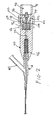
- FIG. 1 illustrates an ultrasound system according to an embodiment for use in ablating and removing occlusive material inside the vessel of an animal or human being.
- the ultrasound system includes an ultrasonic catheter device 10 which has an elongate catheter body 12 having a proximal end 14, a distal end 16, and defining at least one lumen extending longitudinally therethrough.
- the ultrasound catheter device 10 is operatively coupled at its proximal end 14, by way of a Y-connector 18, a catheter knob 20, and a slide collar assembly 22, to an ultrasound transducer housing 24.
- an ultrasound transducer 34 is housed inside the transducer housing 24.
- the ultrasound transducer 34 is connected to a signal generator 26, which can be provided with a foot actuated on-off switch 28.
- the signal generator 26 can be supported by an IV pole 27.
- the on-off switch 28 When the on-off switch 28 is depressed, the signal generator 26 sends an electrical signal to the ultrasound transducer 34, which converts the electrical signal to ultrasound energy.
- Such ultrasound energy subsequently passes through the catheter device 10 and is delivered to the distal end 16.
- an ultrasound transmission member 32 extends through the lumen of the catheter 10 from the distal end 16 to the proximal end 14.
- the ultrasound transducer 34 is coupled via a sonic connector 36 (described in greater detail below) to the ultrasound transmission member 32, so that the ultrasound energy can be passed through the sonic connector 36 and the ultrasound transmission member 32 to be delivered to the distal end 16 of the catheter 10.
- a guidewire 30, which can be any conventional monorail or over-the-wire guidewire, may be utilized in conjunction with the catheter 10 in a manner that is well-known in the catheter art.
- the frontal portion of the Y-connector 18 is connected to the proximal end 12 of the catheter 10 using techniques that are well-known in the catheter art.
- An injection pump (not shown) or IV bag (not shown) can be connected, by way of an infusion tube (not shown), to an infusion port or sidearm 40 of the Y-connector 18.
- the injection pump can be used to infuse coolant fluid (e.g., 0.9% NaCl solution) into and/or through the lumen of the catheter 10.
- coolant fluid e.g. 0.9% NaCl solution
- Such flow of coolant fluid may be utilized to prevent overheating of the ultrasound transmission member 32 extending longitudinally through the lumen of the catheter 10.
- Such flow of the coolant fluid through the lumen of the catheter 10 serves to bathe the outer surface of the ultrasound transmission member 32, thereby providing for an equilibration of temperature between the coolant fluid and the ultrasound transmission member 32.
- the temperature and/or flow rate of coolant fluid may be adjusted to provide adequate cooling and/or other temperature control of the ultrasound transmission member 32.
- the injection pump may be utilized to infuse a radiographic contrast medium into the catheter 10 for purposes of imaging. Examples of iodinated radiographic contrast media which may be selectively infused into the catheter 10 via the injection pump are commercially available as Angiovist 370 from Berlex Labs, Wayne, N.J. and Hexabrix from Malinkrodt, St. Louis, MO.
- the proximal end of the ultrasound transmission member 32 is attached to the sonic connector 36 which is configured to effect operative and removable attachment of the proximal end of the ultrasound transmission member 32 to the distal horn 42 of the ultrasound transducer 34.
- the sonic connector 36 is preferably configured and constructed to permit passage of ultrasound energy through the ultrasound transmission member 32 with minimal lateral side-to-side movement of the ultrasound transmission member 32 while, at the same time, permitting unrestricted longitudinal forward/backward vibration or movement of the ultrasound transmission member 32.
- the ultrasound transmission member 32 may be formed of any material capable of effectively transmitting the ultrasonic energy from the ultrasound transducer 34 to the distal end 16 of the catheter 10, including but not necessarily limited to metal, plastic, hard rubber, ceramic, fiber optics, crystal, polymers, and/or composites thereof. All or a portion of the ultrasound transmission member 32 may be formed of one or more materials which exhibit super-elasticity. Such materials should preferably exhibit super-elasticity consistently within the range of temperatures normally encountered by the ultrasound transmission member 32 during operation of the catheter 10. Specifically, all or part of the ultrasound transmission member 32 may be formed of one or more metal alloys known as "shape memory alloys". Such super-elastic metal alloys are well-known in the art and will not be described in any further detail herein.
- the proximal end of the Y-connector 18 is attached to the distal end of the catheter knob 20 by threadably engaging the proximal end of the Y-connector 18 inside a threaded distal bore 44 at the distal end of the catheter knob 20.
- O-rings 46 are provided in the threaded distal bore 44 to minimize transverse vibrations.
- the proximal end of the catheter knob 20 receives the extension 70 of the transducer housing 24 and is supported by the slide collar assembly 22.
- the slide collar assembly 22 is positioned over the distal end of the transducer housing 24, and has a non-supporting position where the slide collar assembly 22 is retracted towards the transducer housing 24, and has a supporting position where the slide collar assembly 22 is extended to cover at least a portion of the catheter knob 20.
- the slide collar assembly 22 functions as a support member that is disposed on the transducer housing 24 to support at least a portion of the catheter knob 20.
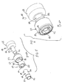
- the slide collar assembly 22 has an inner ring 50 (also referred to as collar 50) and an outer ring 52 (also referred to as collar 52).
- the inner ring 50 has a bore 54 and a longitidunal slit 58 that extends through the length of the inner ring 50.
- the distal portion of the bore 54 can be stepped as shown at 55 (see FIG. 3 ) to function as a pushing surface that pushes a nesting piece 94 (described below) in a distal direction as the inner ring 50 is moved from the non-supporting position to the supporting position.
- the outer ring 52 also has a bore 56, and has a narrowed proximal end 57.
- the inner ring 50 is retained inside the bore 56 of the outer ring 52 and abuts the narrowed proximal end 57 which acts as a stop to limit the proximal movement of the inner ring 50.
- Each of the inner ring 50 and the outer ring 52 has an opening 60 and 62, respectively, that are aligned with each other and that are adapted to receive a locking pin 64.
- a tubular inner sleeve 66 extends through the inside of the bore 54 of the inner ring 50 to ensleeve the first extension 70 of the transducer housing 24, as explained below.
- the sleeve 66 has a proximal section 80 and an enlarged distal section 82.
- the inner ring 50 is normally fitted around the proximal section 80 when the slide collar assembly 22 is in the non-supporting position, but the inner ring 50 is fitted around the distal section 82 when the slide collar assembly 22 is in the supporting position.
- providing the distal section 82 in an enlarged configuration allows for the inner ring 50 to achieve a friction-fit with the distal section 82, while the inner ring 50 experiences a loose fit over the proximal section 80.
- the transducer housing 24 has a cylindrical wall 68 having a distal extension that comprises two stepped cylindrical extensions 70 and 72 extending from the distal end of the cylindrical wall 68.
- the first extension 70 is attached to the distal end of the cylindrical wall 68, and has a greater outer diameter than the second extension 72 that is attached to the distal end of the first extension 70.
- a throughbore 76 extends from the hollow interior 78 of the cylindrical wall 68 and through the extensions 70 and 72. The throughbore 76 can have the same diameter throughout its length.
- the second extension 72 is adapted to be received inside the proximal bore 90 of the catheter knob 20, while the first extension 70 is received inside the sleeve 66.
- an opening 84 is provided in the proximal section 80 of the sleeve 66 and is aligned with a corresponding opening 86 on the first extension 70, with the openings 84, 86 adapted to receive a locking pin 88 that secures the sleeve 66 to the first extension 70 at a fixed position.
- a longitudinal slot 92 is provided on the sleeve 66.
- the slot 92 is opened.
- the inner ring 50 is positioned over the distal section 82 and compresses the enlarged distal section 82 to close the slot 92.
- the sleeve 66 provides a frictional grip of the proximal end 91 of the catheter knob 20.
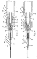
- the catheter knob 20 has a proximal bore 90 that can be sleeved over the second extension 72 in a manner such that the outer surface of the catheter knob 20 can be substantially flush with the outer surface of the first extension 70 (as best shown in FIGS. 3 and 4 ).
- the proximal bore 90 houses the sonic connector 36 and a nesting piece 94.
- An elastic element 96 such as a spring, is seated in the distal part of the proximal bore 90, and has one end carried on a projection 98 provided at the distal end of the nesting piece 94.
- the nesting piece 94 has a generally cylindrical configuration and has a receptacle 100 which functions to selectively retain the sonic connector 36, as will be explained in greater detail below.
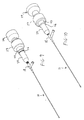
- a control ring 110 is positioned around the outer surface 112 of the catheter knob 20. The control ring 112 cooperates with the nesting piece 94 to move the nesting piece 94 in a reciprocal manner inside the proximal bore 90 of the catheter knob 20, as explained below.
- the nesting piece 94 has two opposite and aligned openings 102; only the top opening 102 is shown in FIG. 7 , but the bottom opening is the same and is aligned on a straight line with the top opening 102.
- the catheter knob 20 has two opposite and aligned channels 104; only the top channel 104 is shown in FIG. 7 , but the bottom channel is the same and is aligned on a straight line with the top channel 104.
- the control ring 110 has two opposite and aligned openings 114. The channels 104 and the openings 102, 114 are aligned, as best shown in FIGS. 3 and 4 .
- each pin 106 adapted to be fitted inside a corresponding set of channel 104 and openings 102, 114, so as to couple the control ring 110 and the nesting piece 94 as a unitary moving piece.
- the width of the channels 104 define the distal and proximal limits of movement for the control ring 110 and the nesting piece 94.
- the catheter knob 20 also has an annular flange 116 provided about its outer surface 112 that also defines the distal limit of the movement of the control ring 110.
- the sonic connector 36 is shown in FIGS. 3-4 as connecting the transducer horn 42 (e.g., with a threaded connection) with the ultrasound transmission member 32.
- the sonic connector 36 is always located at a fixed position inside the proximal bore 90 of the catheter knob 20.
- the elastic element 96 normally biases the nesting piece 94 in the proximal direction so that the sonic connector 36 is received inside the receptacle 100 of the nesting piece 94 to be supported by the nesting piece 94.
- the proximal movement of the nesting piece 94 will cause the pins 106 to move in the proximal direction inside the channels 104, thereby causing the control ring 110 to move proximally away from the flange 116.
- the outer ring 52 and the inner ring 50 are positioned completely over the proximal section 80 of the sleeve 66, with the narrowed proximal end 57 positioned adjacent the cylindrical wall 68 of the transducer housing 24.
- the distal movement of the inner ring 50 will cause the inner surface of the inner ring 50 to engage the enlarged distal section 82 of the sleeve 66, which functions to close the slot 92 so as to frictionally grip the proximal portion 91 of the knob 20 when the slide collar assembly 22 is in the supporting position.
- the flange 116 and the width of the channels 104 function as stops to limit the distal movement of the control ring 110.
- the sonic connector 36 In the supporting position, the sonic connector 36 is not supported by the nesting piece 94 so that the sonic connector 36 can be free from any component or material interfaces, thereby promoting improved ultrasound energy propagation.
- the medical procedure can then be carried out while the slide collar assembly 22 is in the supporting position.
- the above-described steps are reversed.
- the combined inner and outer rings 50, 52 are retracted in the proximal direction so that they are now positioned over the proximal section 80 of the sleeve 66.
- the bias of the elastic element 96 will push the nesting piece 94 in the proximal direction so that the sonic connector 36 is received inside the receptacle 100 of the nesting piece 94.
- the proximal movement of the nesting piece 94 will cause the pins 106 to move in the proximal direction inside the channels 104, thereby causing the control ring 110 to move proximally away from the flange 116. Now, the catheter 10 can be disconnected from the transducer 34.
Landscapes
- Health & Medical Sciences (AREA)
- Surgery (AREA)
- Engineering & Computer Science (AREA)
- Life Sciences & Earth Sciences (AREA)
- Biomedical Technology (AREA)
- Nuclear Medicine, Radiotherapy & Molecular Imaging (AREA)
- Vascular Medicine (AREA)
- Orthopedic Medicine & Surgery (AREA)
- Mechanical Engineering (AREA)
- Heart & Thoracic Surgery (AREA)
- Medical Informatics (AREA)
- Molecular Biology (AREA)
- Animal Behavior & Ethology (AREA)
- General Health & Medical Sciences (AREA)
- Public Health (AREA)
- Veterinary Medicine (AREA)
- Ultra Sonic Daignosis Equipment (AREA)
Claims (12)
- Système à ultrasons, comportant:un transducteur ultrasonore (34) présentant un boîtier de transducteur (24) qui présente une extrémité distale, ainsi qu'un pavillon (42) prévu à l'extrémité distale du boîtier de transducteur (24) ;un élément de transmission d'ultrasons (32) présentant une extrémité proximale ;un connecteur sonique (36) qui est relié à l'extrémité proximale de l'élément de transmission d'ultrasons (32) et qui peut être relié au pavillon (42), etun bouton de cathéter (20) entourant une extrémité proximale de l'élément de transmission d'ultrasons (32) et présentant une extrémité proximale pouvant être raccordée à l'extrémité distale du boîtier de transducteur (24), le bouton de cathéter (20) présentant un alésage proximal logeant le connecteur sonique (36) ;caractérisé en ce qu'une pièce d'emboitement (94) est retenue à l'intérieur de l'alésage proximal (90) du bouton de cathéter (20), la pièce d'emboitement (94) étant mobile depuis une première position, dans laquelle le connecteur sonique (36) est reçu dans la pièce d'emboitement (94), vers une deuxième position, dans laquelle le connecteur sonique (36) est séparé de la pièce d'emboitement (94) lorsque de l'énergie ultrasonore est propagée à travers l'élément de transmission d'ultrasons (32).
- Système selon la revendication 1, comportant en outre :des moyens (96) pour solliciter la pièce d'emboitement (94) depuis la deuxième position vers la première position ; etdes moyens (110) pour déplacer la pièce d'emboitement (94) depuis la première position vers la deuxième position.
- Système selon la revendication 1, comportant en outre :un élément élastique (96) retenu à l'intérieur de l'alésage proximal (90) du bouton de cathéter (20) pour solliciter la pièce d'emboitement (94) depuis la deuxième position vers la première position, etun anneau de commande (110) relié de manière fonctionnelle à la pièce d'emboitement (94) pour déplacer la pièce d'emboitement (94) depuis la première position vers la deuxième position.
- Système selon la revendication 1, 2 ou 3, comportant en outre :un collier (22) qui est positionné mobile au-dessus de l'extrémité distale du boîtier de transducteur (24) et qui est mobile depuis une première position, dans laquelle le collier (22) est espacé de l'anneau de commande (110), vers une deuxième position, dans laquelle le collier (22) s'engage sur l'anneau de commande (110) et le pousse.
- Système selon la revendication 4, comportant en outre des moyens pour maintenir le collier (22) dans la deuxième position.
- Système selon la revendication 4 ou 5, dans lequel le collier (22) présente une bague intérieure (50) présentant un alésage (54), ainsi qu'une bague extérieure (52) présentant un alésage (56), la bague intérieure (50) étant reçue dans l'alésage de l'anneau extérieur (52).
- Système selon la revendication 6, dans lequel l'extrémité proximale du bouton de cathéter (20) est partiellement agencée à l'intérieur de l'alésage (54) de la bague intérieure (50) lorsque la bague intérieure (50) se trouve dans la deuxième position.
- Système selon la revendication 6, comportant en outre une douille (66) partiellement retenue à l'intérieur de l'alésage (54) de la bague intérieure (50), la douille (66) présentant une fente longitudinale (92), et dans lequel la bague intérieure (50) et la bague extérieure (52) ont chacune un orifice (56, 60), un pion (64) s'étendant à travers l'orifice de la bague intérieure (50) et l'orifice de la bague extérieure (52).
- Système selon la revendication 8, dans lequel la fente (92) est ouverte lorsque la pièce d'emboitement (94) se trouve dans la première position, et la fente (92) est fermée lorsque la pièce d'emboitement (94) se trouve dans la deuxième position.
- Système selon la revendication 9, dans lequel la douille (66) saisit le bouton de cathéter (20) lorsque la fente (92) est fermée.
- Système selon la revendication 3, dans lequel le bouton de cathéter (20) présente un canal longitudinal (104) et dans lequel la pièce d'emboitement (94) et l'anneau de commande (110) ont chacun un orifice (102, 114), un pion (106) s'étendant à travers l'orifice dans la pièce d'emboitement (94) et à travers l'orifice dans l'anneau de commande (110) et se déplaçant dans le canal (104).
- Procédé de raccordement d'un système à ultrasons durant une procédure médicale, comportant :a) prévoir un système à ultrasons présentant :un transducteur ultrasonore (34) qui comporte un boîtier de transducteur (24) présentant une extrémité distale, ainsi qu'un pavillon (42) prévu à l'extrémité distale du boîtier de transducteur ;un élément de transmission d'ultrasons (32) présentant une extrémité proximale ;un connecteur sonique (36) qui est relié à l'extrémité proximale de l'élément de transmission d'ultrasons (32) et qui peut être relié au pavillon (42), etun bouton de cathéter (20) entourant une extrémité proximale de l'élément de transmission d'ultrasons (32) et présentant une extrémité proximale pouvant être raccordée à l'extrémité distale du boîtier de transducteur (24), le bouton de cathéter (20) présentant un alésage proximal (90) logeant le connecteur sonique (36) ; etune pièce d'emboitement (94) retenue à l'intérieur de l'alésage proximal (90) du bouton de cathéter (20) ;b) déplacer la pièce d'emboitement (94) depuis une première position, dans laquelle le connecteur sonique (36) est reçu dans la pièce d'emboitement (94), vers une deuxième position, dans laquelle le connecteur sonique (36) est séparé de la pièce d'emboitement (94) lorsque l'énergie ultrasonore est propagée à travers l'élément de transmission d'ultrasons (32).
Applications Claiming Priority (1)
| Application Number | Priority Date | Filing Date | Title |
|---|---|---|---|
| PCT/US2003/030883 WO2005037105A1 (fr) | 2002-09-20 | 2003-09-19 | Connecteur permettant de fixer un catheter a ultrasons sur un transducteur |
Publications (3)
| Publication Number | Publication Date |
|---|---|
| EP1663008A1 EP1663008A1 (fr) | 2006-06-07 |
| EP1663008A4 EP1663008A4 (fr) | 2008-12-31 |
| EP1663008B1 true EP1663008B1 (fr) | 2009-12-30 |
Family
ID=34699467
Family Applications (1)
| Application Number | Title | Priority Date | Filing Date |
|---|---|---|---|
| EP03754997A Expired - Lifetime EP1663008B1 (fr) | 2003-09-19 | 2003-09-19 | Connecteur permettant de fixer un catheter a ultrasons sur un transducteur |
Country Status (3)
| Country | Link |
|---|---|
| EP (1) | EP1663008B1 (fr) |
| AU (1) | AU2003272796A1 (fr) |
| DE (1) | DE60330813D1 (fr) |
Family Cites Families (2)
| Publication number | Priority date | Publication date | Assignee | Title |
|---|---|---|---|---|
| US5417672A (en) * | 1993-10-04 | 1995-05-23 | Baxter International Inc. | Connector for coupling an ultrasound transducer to an ultrasound catheter |
| US5989208A (en) * | 1997-05-16 | 1999-11-23 | Nita; Henry | Therapeutic ultrasound system |
-
2003
- 2003-09-19 DE DE60330813T patent/DE60330813D1/de not_active Expired - Lifetime
- 2003-09-19 AU AU2003272796A patent/AU2003272796A1/en not_active Abandoned
- 2003-09-19 EP EP03754997A patent/EP1663008B1/fr not_active Expired - Lifetime
Also Published As
| Publication number | Publication date |
|---|---|
| DE60330813D1 (de) | 2010-02-11 |
| EP1663008A4 (fr) | 2008-12-31 |
| AU2003272796A1 (en) | 2005-05-05 |
| EP1663008A1 (fr) | 2006-06-07 |
Similar Documents
| Publication | Publication Date | Title |
|---|---|---|
| US11426189B2 (en) | Connector for securing ultrasound catheter to transducer | |
| US6942620B2 (en) | Connector for securing ultrasound catheter to transducer | |
| US6702748B1 (en) | Connector for securing ultrasound catheter to transducer | |
| EP2417920B1 (fr) | Système thérapeutique à ultrasons | |
| US8133236B2 (en) | Ultrasound catheter having protective feature against breakage | |
| EP2298194B1 (fr) | Système thérapeutique utilisant des ultrasons | |
| US8506519B2 (en) | Pre-shaped therapeutic catheter | |
| US6007514A (en) | Ultrasound system with pathfinding guidewire | |
| US10835267B2 (en) | Ultrasound catheter having protective feature against breakage | |
| EP0820727B1 (fr) | Dispositif de cathéter ultrasonique pour angioplastie | |
| US20050124877A1 (en) | Device and method for supporting placement of a therapeutic device in a blood vessel | |
| EP1663008B1 (fr) | Connecteur permettant de fixer un catheter a ultrasons sur un transducteur | |
| JPH08117243A (ja) | 多数の超音波伝達部材を有した超音波切除カテーテル装置 |
Legal Events
| Date | Code | Title | Description |
|---|---|---|---|
| PUAI | Public reference made under article 153(3) epc to a published international application that has entered the european phase |
Free format text: ORIGINAL CODE: 0009012 |
|
| 17P | Request for examination filed |
Effective date: 20060313 |
|
| AK | Designated contracting states |
Kind code of ref document: A1 Designated state(s): DE FR |
|
| DAX | Request for extension of the european patent (deleted) | ||
| RBV | Designated contracting states (corrected) |
Designated state(s): DE FR |
|
| A4 | Supplementary search report drawn up and despatched |
Effective date: 20081127 |
|
| RIC1 | Information provided on ipc code assigned before grant |
Ipc: A61B 17/22 20060101ALI20081121BHEP Ipc: A61B 17/00 20060101ALN20081121BHEP Ipc: A61B 8/14 20060101AFI20050503BHEP Ipc: A61B 17/32 20060101ALN20081121BHEP |
|
| 17Q | First examination report despatched |
Effective date: 20090211 |
|
| GRAP | Despatch of communication of intention to grant a patent |
Free format text: ORIGINAL CODE: EPIDOSNIGR1 |
|
| GRAS | Grant fee paid |
Free format text: ORIGINAL CODE: EPIDOSNIGR3 |
|
| GRAA | (expected) grant |
Free format text: ORIGINAL CODE: 0009210 |
|
| AK | Designated contracting states |
Kind code of ref document: B1 Designated state(s): DE FR |
|
| REF | Corresponds to: |
Ref document number: 60330813 Country of ref document: DE Date of ref document: 20100211 Kind code of ref document: P |
|
| PLBE | No opposition filed within time limit |
Free format text: ORIGINAL CODE: 0009261 |
|
| STAA | Information on the status of an ep patent application or granted ep patent |
Free format text: STATUS: NO OPPOSITION FILED WITHIN TIME LIMIT |
|
| 26N | No opposition filed |
Effective date: 20101001 |
|
| REG | Reference to a national code |
Ref country code: FR Ref legal event code: PLFP Year of fee payment: 14 |
|
| REG | Reference to a national code |
Ref country code: FR Ref legal event code: PLFP Year of fee payment: 15 |
|
| REG | Reference to a national code |
Ref country code: FR Ref legal event code: PLFP Year of fee payment: 16 |
|
| PGFP | Annual fee paid to national office [announced via postgrant information from national office to epo] |
Ref country code: DE Payment date: 20220616 Year of fee payment: 20 |
|
| PGFP | Annual fee paid to national office [announced via postgrant information from national office to epo] |
Ref country code: FR Payment date: 20220819 Year of fee payment: 20 |
|
| REG | Reference to a national code |
Ref country code: DE Ref legal event code: R071 Ref document number: 60330813 Country of ref document: DE |