EP1662236A2 - Coriolis-mass flow meter and method of manufacturing a measuring tube for a Coriolis-mass flow meter - Google Patents
Coriolis-mass flow meter and method of manufacturing a measuring tube for a Coriolis-mass flow meter Download PDFInfo
- Publication number
- EP1662236A2 EP1662236A2 EP05019474A EP05019474A EP1662236A2 EP 1662236 A2 EP1662236 A2 EP 1662236A2 EP 05019474 A EP05019474 A EP 05019474A EP 05019474 A EP05019474 A EP 05019474A EP 1662236 A2 EP1662236 A2 EP 1662236A2
- Authority
- EP
- European Patent Office
- Prior art keywords
- measuring tube
- polyetheretherketone
- fiber
- coriolis mass
- reinforced
- Prior art date
- Legal status (The legal status is an assumption and is not a legal conclusion. Google has not performed a legal analysis and makes no representation as to the accuracy of the status listed.)
- Granted
Links
Images

Classifications
-
- G—PHYSICS
- G01—MEASURING; TESTING
- G01F—MEASURING VOLUME, VOLUME FLOW, MASS FLOW OR LIQUID LEVEL; METERING BY VOLUME
- G01F1/00—Measuring the volume flow or mass flow of fluid or fluent solid material wherein the fluid passes through a meter in a continuous flow
- G01F1/76—Devices for measuring mass flow of a fluid or a fluent solid material
- G01F1/78—Direct mass flowmeters
- G01F1/80—Direct mass flowmeters operating by measuring pressure, force, momentum, or frequency of a fluid flow to which a rotational movement has been imparted
- G01F1/84—Coriolis or gyroscopic mass flowmeters
- G01F1/8404—Coriolis or gyroscopic mass flowmeters details of flowmeter manufacturing methods
-
- G—PHYSICS
- G01—MEASURING; TESTING
- G01F—MEASURING VOLUME, VOLUME FLOW, MASS FLOW OR LIQUID LEVEL; METERING BY VOLUME
- G01F1/00—Measuring the volume flow or mass flow of fluid or fluent solid material wherein the fluid passes through a meter in a continuous flow
- G01F1/76—Devices for measuring mass flow of a fluid or a fluent solid material
- G01F1/78—Direct mass flowmeters
- G01F1/80—Direct mass flowmeters operating by measuring pressure, force, momentum, or frequency of a fluid flow to which a rotational movement has been imparted
- G01F1/84—Coriolis or gyroscopic mass flowmeters
- G01F1/8409—Coriolis or gyroscopic mass flowmeters constructional details
-
- G—PHYSICS
- G01—MEASURING; TESTING
- G01F—MEASURING VOLUME, VOLUME FLOW, MASS FLOW OR LIQUID LEVEL; METERING BY VOLUME
- G01F1/00—Measuring the volume flow or mass flow of fluid or fluent solid material wherein the fluid passes through a meter in a continuous flow
- G01F1/76—Devices for measuring mass flow of a fluid or a fluent solid material
- G01F1/78—Direct mass flowmeters
- G01F1/80—Direct mass flowmeters operating by measuring pressure, force, momentum, or frequency of a fluid flow to which a rotational movement has been imparted
- G01F1/84—Coriolis or gyroscopic mass flowmeters
- G01F1/845—Coriolis or gyroscopic mass flowmeters arrangements of measuring means, e.g., of measuring conduits
- G01F1/8468—Coriolis or gyroscopic mass flowmeters arrangements of measuring means, e.g., of measuring conduits vibrating measuring conduits
- G01F1/849—Coriolis or gyroscopic mass flowmeters arrangements of measuring means, e.g., of measuring conduits vibrating measuring conduits having straight measuring conduits
-
- Y—GENERAL TAGGING OF NEW TECHNOLOGICAL DEVELOPMENTS; GENERAL TAGGING OF CROSS-SECTIONAL TECHNOLOGIES SPANNING OVER SEVERAL SECTIONS OF THE IPC; TECHNICAL SUBJECTS COVERED BY FORMER USPC CROSS-REFERENCE ART COLLECTIONS [XRACs] AND DIGESTS
- Y10—TECHNICAL SUBJECTS COVERED BY FORMER USPC
- Y10T—TECHNICAL SUBJECTS COVERED BY FORMER US CLASSIFICATION
- Y10T428/00—Stock material or miscellaneous articles
- Y10T428/13—Hollow or container type article [e.g., tube, vase, etc.]
- Y10T428/1352—Polymer or resin containing [i.e., natural or synthetic]
- Y10T428/139—Open-ended, self-supporting conduit, cylinder, or tube-type article
- Y10T428/1393—Multilayer [continuous layer]
Definitions
- the invention relates to a Coriolis mass flowmeter, comprising a measuring tube which can be excited to oscillate, and to a method for producing a measuring tube for a Coriolis mass flowmeter.
- Coriolis mass flowmeters are well known in the art.
- at least one measuring tube is excited to oscillate, so that Coriolis forces are generated in a medium flowing through the measuring tube.
- These Coriolis forces or deflections of the measuring tube generated thereby are detected in order to be able to conclude on the mass flow, z. B. on the phase shift of the deflections of the measuring tube at its inlet or outlet side.
- K.W. Bonfig Technical Flow Measurement, 3rd edition, 2002, Vulkan-Verlag GmbH, pages 215-226.
- Measuring tubes for Coriolis mass flowmeters are often made of metallic materials such as stainless steel, titanium, tantalum and the like.
- approaches are also known to use non-metallic materials for a measuring tube of a Coriolis mass flowmeter.
- the measuring tube of a Coriolis mass flowmeter consists of carbon obtained by pyrolysis of non-meltable plastics.
- DE 100 37 784 A1 discloses a Coriolis mass flowmeter with a measuring tube made of ceramic.
- Coriolis mass flowmeters with a measuring tube made of a non-metallic material may be advantageous, inter alia, since they can also be used for flow measurement in chemically aggressive media, ie have a high corrosion resistance.
- the previously derived and indicated object is achieved in that the measuring tube has fiber-reinforced polyetheretherketone with an inner coating of pure polyetheretherketone.
- the invention thus provides for the combination of polyetheretherketone (PEEK) in fiber-reinforced form with pure polyetheretherketone as inner coating, in which context "pure” should mean that polyether etherketone is provided as such, ie without fiber reinforcement.
- PEEK polyetheretherketone
- pure should mean that polyether etherketone is provided as such, ie without fiber reinforcement.
- the term “pure” is not meant here, so that although no fiber reinforcements in the pure PEEK should be provided, the addition of other material is not excluded.
- it is provided that is used as a "pure” PEEK virtually additive-free PEEK to ensure high corrosion resistance of the inner coating.
- the fiber-reinforced PEEK it is thus possible in principle to use such a fiber material that is admixed with the PEEK without orientation. According to a preferred embodiment of the invention, however, it is provided that the fibers provided for reinforcement have at least one predetermined orientation in the PEEK. It is further preferred that the fibers extend in the longitudinal direction of the measuring tube and / or helical, preferably double helical.
- a plurality of fiber materials are useful for reinforcing the polyetheretherketone. According to a preferred embodiment of the invention, however, it is provided that graphite fiber-reinforced polyetheretherketone is used.
- the wall of the measuring tube is formed of fiber-reinforced polyetheretherketone and the inner surface of the wall is completely provided with the inner coating of pure polyetheretherketone. It is particularly particularly preferred that the wall of the measuring tube made of fiber-reinforced polyetheretherketone or / and the inner coating of pure polyetheretherketone is wound.
- the wall of the measuring tube made of fiber-reinforced polyetheretherketone to be amplified sites has a greater wall thickness than at other locations.
- additional windings or layers of the fiber-reinforced polyetheretherketone have been applied there in the production of the wall of the measuring tube.
- the transition from the fiber-reinforced polyetheretherketone to the inner coating of pure polyetheretherketone can basically be arbitrary. According to a preferred embodiment of the invention, however, it is provided that the wall of fiber-reinforced polyetheretherketone and the inner coating of pure polyetheretherketone have a compound prepared by annealing.
- the above-mentioned and indicated object is achieved in that at least one strip of pure polyetheretherketone is wound onto a winding mandrel and the pure polyetheretherketone with at least one layer of a fiber-reinforced polyetheretherketone is wrapped.
- graphite fiber-reinforced polyetheretherketone is used according to a preferred embodiment of the invention, as already stated above.
- fiber-reinforced polyetheretherketone in which the fibers intended for reinforcement are randomly oriented.
- fiber-reinforced polyetheretherketone is used whose provided for reinforcement fibers in at least one predetermined Direction are oriented.
- the fiber-reinforced polyetheretherketone is wound up in such a way that the fibers extend in the longitudinal direction of the tube and / or helically, preferably in a double helical fashion. In this way, a measuring tube is achieved, which is highly pressure resistant and has a moderate temperature expansion.
- the outer surface of the wound on the winding mandrel pure polyetheretherketone is etched before wrapping with the fiber-reinforced polyetheretherketone, preferably namely chemically etched.
- the measuring tube is annealed with the wound of the fiber-reinforced polyetheretherketone pure polyetheretherketone, that is exposed to a heat treatment.
- the annealing at a temperature between 80 and 120 ° C, most preferably at about 100 ° C takes place. It is intended to carry out this temperature treatment for a period of 3 to 5 hours, preferably for about 4 hours. Such a temperature treatment may in principle be sufficient.
- the form of the measuring tube achieved by winding can already be used for a Coriolis mass flowmeter.
- adjustments of the measuring tube, in particular on the amplified by additional windings with fiber reinforced polyetheretherketone bodies can be effected in that the measuring tube is mechanically processed, for. B. by machining processes.
- the measuring tube 1 is prepared as described below:
- a 25.4 mm diameter winding mandrel (not shown) is coated with a pure PEEK film strip of 0.05 gauge thickness mm wound with a respective lateral overlap of 5 mm.
- the filmstrips are then joined together at their overlaps by being heated under pressure. Thereafter, the outer surface of the wound on the winding mandrel wound pure polyetheretherketone is chemically etched, using a chromic acid-based solution to improve the connection with the subsequently wound layer of fiber-reinforced PEEK.
- points 2 of the measuring tube 1 further layers of graphite fiber reinforced PEEK are applied, as shown in FIG.
- These reinforced points 2 are used to attach other devices of the Coriolis mass flow meter such as an inner cylinder 3 and for mounting the measuring tube 1 in a housing 4 for the Coriolis mass flowmeter.
- these reinforcing sites 2 are also machined to achieve conical surfaces.
- the measuring tube 1 is annealed, namely at 100 ° C for four hours and then at a temperature of 60 ° C for another four hours.
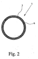
- a measuring tube 1 for a Coriolis mass flowmeter with a length of 620 mm, an inner diameter of 25.4 mm and an outer diameter of about 26.4 mm is achieved, which has a structure, as again in Fig. 2 schematically and not proportionally represented as a section through the measuring tube 1 outside of a reinforced point 2.
- a test measurement with water flowing through the measuring tube 1 results in a natural frequency for the first mode of the measuring tube 1 at about 192 Hz, so that the measuring tube produced in this way is well suited for use in a Coriolis mass flowmeter.
Landscapes
- Physics & Mathematics (AREA)
- Fluid Mechanics (AREA)
- General Physics & Mathematics (AREA)
- Engineering & Computer Science (AREA)
- Manufacturing & Machinery (AREA)
- Measuring Volume Flow (AREA)
- Rigid Pipes And Flexible Pipes (AREA)
Abstract
Description
Die Erfindung betrifft ein Coriolis-Massendurchflußmeßgerät, mit einem zu Schwingungen anregbaren Meßrohr sowie ein Verfahren zur Herstellung eines Meßrohrs für ein Coriolis-Massendurchflußmeßgerät.The invention relates to a Coriolis mass flowmeter, comprising a measuring tube which can be excited to oscillate, and to a method for producing a measuring tube for a Coriolis mass flowmeter.
Coriolis-Massendurchflußmeßgeräte sind aus der Praxis gut bekannt. Bei dieser Art von Massendurchflußmeßgeräten wird wenigstens ein Meßrohr zu Schwingungen angeregt, so daß in einem durch das Meßrohr fließenden Medium Coriolis-Kräfte erzeugt werden. Diese Coriolis-Kräfte bzw. dadurch generierte Auslenkungen des Meßrohrs werden erfaßt, um damit auf den Massendurchfluß rückschließen zu können, z. B. über die Phasenverschiebung der Auslenkungen des Meßrohrs an seiner Einlauf- bzw. Auslaufseite. Diesbezüglich wird allgemein verwiesen auf "K. W. Bonfig, Technische Durchflußmessung, 3. Auflage, 2002, Vulkan-Verlag GmbH, Seiten 215 - 226".Coriolis mass flowmeters are well known in the art. In this type of mass flowmeters, at least one measuring tube is excited to oscillate, so that Coriolis forces are generated in a medium flowing through the measuring tube. These Coriolis forces or deflections of the measuring tube generated thereby are detected in order to be able to conclude on the mass flow, z. B. on the phase shift of the deflections of the measuring tube at its inlet or outlet side. In this regard, reference is generally made to "K.W. Bonfig, Technical Flow Measurement, 3rd edition, 2002, Vulkan-Verlag GmbH, pages 215-226".
Meßrohre für Coriolis-Massendurchflußmeßgeräte werden häufig aus metallischen Materialien hergestellt, wie Edelstahl, Titan, Tantal u.a. Es sind jedoch auch Ansätze bekannt, nichtmetallische Materialien für ein Meßrohr eines Coriolis-Massendurchflußmeßgeräts zu verwenden. Gemäß der DE 41 19 396 C1 ist beispielsweise vorgesehen, daß das Meßrohr eines Coriolis-Massendurchflußmeßgeräts aus durch Pyrolyse unschmelabarer Kunststoffe gewonnenem Kohlenstoff besteht. Ferner ist aus der DE 100 37 784 A1 ein Coriolis-Massendurchflußmeßgerät mit einem Meßrohr aus Keramik bekannt. Coriolis-Massendurchflußmeßgeräte mit einem Meßrohr aus einem nichtmetallischen Werkstoff können unter anderem deshalb vorteilhaft sein, da sie auch zur Durchflußmessung bei chemisch aggressiven Medien einsetzbar sind, also eine hohe Korrosionsbeständigkeit aufweisen.Measuring tubes for Coriolis mass flowmeters are often made of metallic materials such as stainless steel, titanium, tantalum and the like. However, approaches are also known to use non-metallic materials for a measuring tube of a Coriolis mass flowmeter. According to DE 41 19 396 C1, for example, it is provided that the measuring tube of a Coriolis mass flowmeter consists of carbon obtained by pyrolysis of non-meltable plastics. Furthermore, DE 100 37 784 A1 discloses a Coriolis mass flowmeter with a measuring tube made of ceramic. Coriolis mass flowmeters with a measuring tube made of a non-metallic material may be advantageous, inter alia, since they can also be used for flow measurement in chemically aggressive media, ie have a high corrosion resistance.
Es ist die Aufgabe der Erfindung, ein derartiges Coriolis-Massendurchflußmeßgerät sowie ein derartiges Verfahren zur Herstellung eines Meßrohrs eines Coriolis-Massendurchflußmeßgeräts anzugeben, mit denen eine Massendurchflußmessung von chemisch aggressiven Medien ermöglicht wird, wobei gleichzeitig eine optimale Anpassung der Parameter des Coriolis-Massendurchflußmeßgeräts, wie Temperatur- und Druckbeständigkeit, an die jeweilige Anwendung ermöglicht wird.It is the object of the invention to provide such a Coriolis mass flowmeter and such a method for producing a measuring tube of a Coriolis mass flowmeter, which allows a mass flow measurement of chemically aggressive media, wherein at the same time an optimal adaptation of the parameters of the Coriolis mass flowmeter, such as temperature and pressure resistance, is made possible to the particular application.
Ausgehend von dem eingangs beschriebenen Coriolis-Massendurchflußmeßgerät ist die zuvor hergeleitete und aufgezeigte Aufgabe dadurch gelöst, daß das Meßrohr faserverstärktes Polyetheretherketon mit einer Innenbeschichtung aus reinem Polyetheretherketon aufweist.Starting from the Coriolis mass flowmeter described above, the previously derived and indicated object is achieved in that the measuring tube has fiber-reinforced polyetheretherketone with an inner coating of pure polyetheretherketone.
Die Erfindung sieht also die Kombination von Polyetheretherketon (PEEK) in faserverstärkter Form mit reinem Polyetheretherketon als Innenbeschichtung vor, wobei in diesem Zusammenhang "rein" bedeuten soll, daß Polyether-etherketon als solches, also ohne Faserverstärkung, vorgesehen ist. Als ein Hinweis auf einen besonderen Reinheitsgrad ist die Bezeichnung "rein" vorliegend nicht gemeint, so daß zwar keine Faserverstärkungen in dem reinen PEEK vorgesehen sein sollen, die Hinzufügung von anderem Material jedoch nicht ausgeschlossen ist. Gemäß einer bevorzugten Weiterbildung der Erfindung ist jedoch vorgesehen, daß als "reines" PEEK praktisch zusatzfreies PEEK verwendet wird, um eine hohe Korrosionsbeständigkeit der Innenbeschichtung zu gewährleisten.The invention thus provides for the combination of polyetheretherketone (PEEK) in fiber-reinforced form with pure polyetheretherketone as inner coating, in which context "pure" should mean that polyether etherketone is provided as such, ie without fiber reinforcement. As an indication of a particular degree of purity, the term "pure" is not meant here, so that although no fiber reinforcements in the pure PEEK should be provided, the addition of other material is not excluded. According to a preferred embodiment of the invention, however, it is provided that is used as a "pure" PEEK virtually additive-free PEEK to ensure high corrosion resistance of the inner coating.
Bezüglich des faserverstärkten PEEKs kann also grundsätzlich ein derartiges Fasermaterial verwendet werden, das dem PEEK ohne Orientierung beigemischt ist. Gemäß einer bevorzugten Weiterbildung der Erfindung ist jedoch vorgesehen, daß die zur Verstärkung vorgesehenen Fasern im PEEK wenigstens eine vorbestimmte Orientierung aufweisen. Dabei ist es weiterhin bevorzugt, daß die Fasern in Längsrichtung des Meßrohres und/oder helixförmig, vorzugsweise doppelhelixförmig, verlaufen.With regard to the fiber-reinforced PEEK, it is thus possible in principle to use such a fiber material that is admixed with the PEEK without orientation. According to a preferred embodiment of the invention, however, it is provided that the fibers provided for reinforcement have at least one predetermined orientation in the PEEK. It is further preferred that the fibers extend in the longitudinal direction of the measuring tube and / or helical, preferably double helical.
Grundsätzlich ist eine Mehrzahl von Fasermaterialien zur Verstärkung des Polyetheretherketons verwendbar. Gemäß einer bevorzugten Weiterbildung der Erfindung ist jedoch vorgesehen, daß graphitfaserverstärktes Polyetheretherketon verwendet wird.Basically, a plurality of fiber materials are useful for reinforcing the polyetheretherketone. According to a preferred embodiment of the invention, however, it is provided that graphite fiber-reinforced polyetheretherketone is used.
Grundsätzlich ist es möglich, faserverstärktes Polyetheretherketon bzw. reines Polyetheretherketon nur teilweise für das Meßrohr zu verwenden. Gemäß einer bevorzugten Weiterbildung der Erfindung ist jedoch vorgesehen, daß die Wand des Meßrohrs aus faserverstärktem Polyetheretherketon gebildet ist und die Innenfläche der Wand vollständig mit der Innenbeschichtung aus reinem Polyetheretherketon versehen ist. Dabei ist es insbesondere besonders bevorzugt, daß die Wand des Meßrohrs aus faserverstärktem Polyetheretherketon oder/und die Innenbeschichtung aus reinem Polyetheretherketon gewickelt ist.In principle, it is possible to use fiber-reinforced polyetheretherketone or pure polyetheretherketone only partially for the measuring tube. According to one preferred embodiment of the invention, however, it is provided that the wall of the measuring tube is formed of fiber-reinforced polyetheretherketone and the inner surface of the wall is completely provided with the inner coating of pure polyetheretherketone. It is particularly particularly preferred that the wall of the measuring tube made of fiber-reinforced polyetheretherketone or / and the inner coating of pure polyetheretherketone is wound.
Ferner kann dabei gemäß einer bevorzugten Weiterbildung der Erfindung vorgesehen sein, daß die Wand des Meßrohrs aus faserverstärktem Polyetheretherketon an zu verstärkenden Stellen eine größere Wandstärke aufweist als an anderen Stellen. Mit anderen Worten sind dort bei der Herstellung der Wand des Meßrohrs also zusätzliche Wicklungen bzw. Schichten des faserverstärkten Polyetheretherketons aufgebracht worden.Furthermore, it can be provided according to a preferred embodiment of the invention that the wall of the measuring tube made of fiber-reinforced polyetheretherketone to be amplified sites has a greater wall thickness than at other locations. In other words, additional windings or layers of the fiber-reinforced polyetheretherketone have been applied there in the production of the wall of the measuring tube.
Der Übergang von dem faserverstärktem Polyetheretherketon auf die Innenbeschichtung aus reinem Polyetheretherketon kann grundsätzlich beliebig sein. Gemäß einer bevorzugten Weiterbildung der Erfindung ist jedoch vorgesehen, daß die Wand aus faserverstärktem Polyetheretherketon und die Innenbeschichtung aus reinem Polyetheretherketon eine durch Tempern hergestellte Verbindung aufweisen.The transition from the fiber-reinforced polyetheretherketone to the inner coating of pure polyetheretherketone can basically be arbitrary. According to a preferred embodiment of the invention, however, it is provided that the wall of fiber-reinforced polyetheretherketone and the inner coating of pure polyetheretherketone have a compound prepared by annealing.
Ausgehend von dem eingangs beschriebenen Verfahren zur Herstellung eines Meßrohrs für ein Coriolis-Massendurchflußmeßgerät ist die weiter oben hergeleitete und aufgezeigte Aufgabe dadurch gelöst, daß wenigstens ein Streifen aus reinem Polyetheretherketon auf einen Wickeldorn aufgewickelt wird und das reine Polyetheretherketon mit wenigstens einer Schicht aus einem faserverstärkten Polyetheretherketon umwickelt wird.Starting from the method described above for producing a measuring tube for a Coriolis mass flowmeter, the above-mentioned and indicated object is achieved in that at least one strip of pure polyetheretherketone is wound onto a winding mandrel and the pure polyetheretherketone with at least one layer of a fiber-reinforced polyetheretherketone is wrapped.
Dabei wird gemäß einer bevorzugten Weiterbildung der Erfindung, wie oben schon ausgeführt, graphitfaserverstärktes Polyetheretherketon verwendet.In this case, graphite fiber-reinforced polyetheretherketone is used according to a preferred embodiment of the invention, as already stated above.
Wie ebenfalls oben schon ausgeführt, ist grundsätzlich derartiges faserverstärktes Polyetheretherketon verwendbar, bei dem die zur Verstärkung vorgesehenen Fasern statistisch orientiert sind. Gemäß einer bevorzugten Weiterbildung der Erfindung wird jedoch faserverstärktes Polyetheretherketon verwendet, dessen zur Verstärkung vorgesehene Fasern in wenigstens einer vorbestimmten Richtung orientiert sind. Gemäß einer bevorzugten Weiterbildung wird dabei das faserverstärkte Polyetheretherketon derart aufgewickelt, daß die Fasern in Längsrichtung des Rohres und/oder helixförmig, vorzugsweise doppelhelixförmig, verlaufen. Auf diese Weise wird ein Meßrohr erzielt, das hoch druckbeständig ist und eine moderate Temperaturausdehnung aufweist.As also stated above, in principle such fiber-reinforced polyetheretherketone can be used, in which the fibers intended for reinforcement are randomly oriented. According to a preferred embodiment of the invention, however, fiber-reinforced polyetheretherketone is used whose provided for reinforcement fibers in at least one predetermined Direction are oriented. According to a preferred refinement, the fiber-reinforced polyetheretherketone is wound up in such a way that the fibers extend in the longitudinal direction of the tube and / or helically, preferably in a double helical fashion. In this way, a measuring tube is achieved, which is highly pressure resistant and has a moderate temperature expansion.
Ferner kann gemäß einer bevorzugten Weiterbildung der Erfindung vorgesehen sein, daß zu verstärkende Stellen des Meßrohrs mit zusätzlichen Verstärkungswicklungen aus faserverstärktem Polyetheretherketon versehen werden. Diese verstärkten Stellen des Meßrohrs können z. B. zur Anbringung zusätzlicher Komponenten an das Meßrohr oder zur Befestigung des Meßrohrs in einem äußeren Rohrleitungssystem verwendet werden.Furthermore, it can be provided according to a preferred embodiment of the invention that are provided to be amplified points of the measuring tube with additional reinforcing windings of fiber reinforced polyetheretherketone. These reinforced points of the measuring tube can, for. B. are used for attaching additional components to the measuring tube or for mounting the measuring tube in an outer piping system.
Gemäß einer bevorzugten Weiterbildung der Erfindung ist ferner vorgesehen, daß einander benachbarte Windungen des reinen Polyetheretherketons einander teilweise überlappend gewickelt werden. Dabei kann insbesondere auch vorgesehen sein, daß die Überlappungen durch Erwärmen, vorzugsweise unter erhöhtem Druck, miteinander verbunden werden.According to a preferred embodiment of the invention it is further provided that adjacent turns of the pure polyetheretherketone are wound each other partially overlapping. It can also be provided in particular that the overlaps are connected to each other by heating, preferably under elevated pressure.
Grundsätzlich ist es nicht unbedingt erforderlich, die Außenfläche des auf den Wickeldorn aufgewickelten reinen Polyetheretherketons vor der Umwicklung mit dem faserverstärkten Polyetheretherketon zu behandeln. Gemäß einer bevorzugten Weiterbildung der Erfindung ist jedoch vorgesehen, daß die Außenfläche des auf den Wickeldorn aufgewickelten reinen Polyetheretherketons vor der Umwicklung mit dem faserverstärkten Polyetheretherketon angeätzt wird, vorzugsweise nämlich chemisch angeätzt wird.In principle, it is not absolutely necessary to treat the outer surface of the wound on the winding mandrel pure polyetheretherketone before wrapping with the fiber-reinforced polyetheretherketone. According to a preferred embodiment of the invention, however, it is provided that the outer surface of the wound on the winding mandrel pure polyetheretherketone is etched before wrapping with the fiber-reinforced polyetheretherketone, preferably namely chemically etched.
Weiterhin ist es gemäß einer bevorzugten Weiterbildung der Erfindung vorgesehen, daß das Meßrohr mit dem von dem faserverstärkten Polyetheretherketon umwickelten reinen Polyetheretherketon getempert wird, also einer Wärmebehandlung ausgesetzt wird. Vorzugsweise ist dabei vorgesehen, daß das Tempern bei einer Temperatur zwischen 80 und 120 °C, ganz besonders bevorzugt bei etwa 100 °C, erfolgt. Es ist vorgesehen, diese Temperaturbehandlung für eine Zeitdauer von 3 bis 5 Stunden, vorzugsweise für etwa 4 Stunden, durchzuführen. Eine derartige Temperaturbehandlung kann grundsätzlich schon ausreichend sein. Gemäß einer bevorzugten Weiterbildung der Erfindung ist jedoch vorgesehen, daß sich ein weiteres Tempern bei einer niedrigeren Temperatur anschließt, vorzugsweise bei einer Temperatur zwischen 50 und 80 °C, ganz besonders bevorzugt bei einer Temperatur von etwa 60 °C. Dieses Tempern bei der niedrigeren Temperatur erfolgt vorzugsweise für eine Zeitdauer von 3 bis 5 Stunden, vorzugsweise für etwa 4 Stunden.Furthermore, it is provided according to a preferred embodiment of the invention that the measuring tube is annealed with the wound of the fiber-reinforced polyetheretherketone pure polyetheretherketone, that is exposed to a heat treatment. Preferably, it is provided that the annealing at a temperature between 80 and 120 ° C, most preferably at about 100 ° C, takes place. It is intended to carry out this temperature treatment for a period of 3 to 5 hours, preferably for about 4 hours. Such a temperature treatment may in principle be sufficient. According to a preferred embodiment of Invention is, however, provided that further annealing at a lower temperature followed, preferably at a temperature between 50 and 80 ° C, most preferably at a temperature of about 60 ° C. This annealing at the lower temperature is preferably carried out for a period of 3 to 5 hours, preferably for about 4 hours.
Grundsätzlich kann die durch Wickeln erzielte Form des Meßrohrs schon für ein Coriolis-Massendurchflußmeßgerät verwendet werden. Es können jedoch Anpassungen des Meßrohrs, insbesondere an den durch zusätzliche Wicklungen mit faserverstärktem Polyetheretherketon verstärkten Stellen dadurch erfolgen, daß das Meßrohr mechanisch bearbeitet wird, z. B. durch spanabhebende Verfahren.In principle, the form of the measuring tube achieved by winding can already be used for a Coriolis mass flowmeter. However, adjustments of the measuring tube, in particular on the amplified by additional windings with fiber reinforced polyetheretherketone bodies can be effected in that the measuring tube is mechanically processed, for. B. by machining processes.
Im einzelnen gibt es nun eine Vielzahl von Möglichkeiten, das erfindungsgemäße Coriolis-Massendurchflußmeßgerät sowie das erfindungsgemäße Verfahren zur Herstellung eines Meßrohrs für ein Coriolis-Massendurchflußmeßgerät auszugestalten und weiterzubilden. Dazu wird auf die den unabhängigen Patentansprüchen nachgeordneten Patentansprüche sowie auf die nachfolgende detaillierte Beschreibung eines bevorzugten Ausführungsbeispiels der Erfmdung unter Bezugnahme auf die Zeichnung verwiesen. In der Zeichnung zeigt
- Fig. 1
- schematisch ein Coriolis-Massendurchflußmeßgerät gemäß einem bevorzugten Ausführungsbeispiel der Erfindung in einem Längsschnitt und
- Fig. 2
- schematisch das Meßrohr des Coriolis-Massendurchflußmeßgeräts gemäß dem aus Fig. 1 ersichtlichen bevorzugten Ausführungsbeispiel der Erfindung in einem Querschnitt.
- Fig. 1
- schematically a Coriolis mass flowmeter according to a preferred embodiment of the invention in a longitudinal section and
- Fig. 2
- schematically the measuring tube of the Coriolis mass flow meter according to the apparent from Fig. 1 preferred embodiment of the invention in a cross section.
Aus Fig. 1 ist ein Coriolis-Massendurchflußmeßgerät gemäß einem bevorzugten Ausführungsbeispiel der Erfindung ersichtlich, dessen Meßrohr 1 wie im folgenden beschrieben hergestellt wird:From Fig. 1, a Coriolis mass flowmeter according to a preferred embodiment of the invention can be seen, the
Ein nicht weiter dargestellten Wickeldorn mit einem Durchmesser von 25,4 mm wird mit einem Filmstreifen aus reinem PEEK mit einer Dicke von 0,05 mm mit einer jeweiligen seitlichen Überlappung von 5 mm überwickelt. Die Filmstreifen werden dann an ihren Überlappungen miteinander verbunden, indem sie unter Druck erwärmt werden. Danach wird die Außenfläche des auf den Wickeldorn aufgewickelten reinen Polyetheretherketons chemisch geätzt, und zwar unter Verwendung einer chromsäurebasierten Lösung, um die Verbindung mit der im folgenden aufzuwickelnden Schicht aus faserverstärktem PEEK zu verbessern.A 25.4 mm diameter winding mandrel (not shown) is coated with a pure PEEK film strip of 0.05 gauge thickness mm wound with a respective lateral overlap of 5 mm. The filmstrips are then joined together at their overlaps by being heated under pressure. Thereafter, the outer surface of the wound on the winding mandrel wound pure polyetheretherketone is chemically etched, using a chromic acid-based solution to improve the connection with the subsequently wound layer of fiber-reinforced PEEK.
Nach dem chemischen Ätzen der Außenfläche des auf den Wickeldorn aufgewickelten reinen Polyetheretherketons werden zwei Lagen von graphitfaserverstärktem Polyetheretherketon mit einer jeweiligen Dicke von 0,125 mm auf das reine PEEK aufgewickelt. Bei dem graphitfaserverstärktem PEEK wird ein derartiges Material verwendet, bei dem die Graphitfasern in eine vorbestimmte Richtung orientiert sind. Die beiden Schichten des graphitfaserverstärkten PEEK werden dabei derart aufgewickelt, daß die Orientierung der Graphitfasern der Längsrichtung des Meßrohrs 1 entspricht. Nachfolgend werden zwei weitere Schichten von graphitfaserverstärktem PEEK mit einer jeweiligen Dicke von 0,125 mm aufgebracht, und zwar derart, daß die Orientierung der Graphitfasern relativ zur Längsrichtung des Meßrohrs 1 +82,5° bzw. -82,5° beträgt. Damit verlaufen die Graphitfasern im graphitfaserverstärktem PEEK also praktisch doppelhelixförmig um das Meßrohr 1 herum. Über die Orientierung der Richtung der zur Verstärkung des PEEK vorgesehenen Fasern können die Dynamik, die thermischen Eigenschaften und die Druckbeständigkeit des Meßrohrs 1 bestimmt werden. Insgesamt ergibt sich damit eine Gesamtwandstärke der Wand 5 des Meßrohrs 1 von 0,5 mm zuzüglich der Wandstärke der Innenbeschichtung 6 von 0,05 mm.After the chemical etching of the outer surface of the wound on the winding mandrel pure polyetheretherketone two layers of graphite fiber reinforced polyetheretherketone with a respective thickness of 0.125 mm are wound onto the pure PEEK. In the graphite fiber reinforced PEEK, such a material is used in which the graphite fibers are oriented in a predetermined direction. The two layers of the graphite fiber reinforced PEEK are wound in such a way that the orientation of the graphite fibers corresponds to the longitudinal direction of the measuring
An vorbestimmten, zu verstärkenden Stellen 2 des Meßrohrs 1 werden weitere Schichten von graphitfaserverstärktem PEEK aufgebracht, wie aus Fig. 1 ersichtlich. Diese verstärkten Stellen 2 dienen zum Anbringen weiterer Einrichtungen des Coriolis-Massendurchflußmeßgeräts wie einem Innenzylinder 3 bzw. zur Befestigung des Meßrohrs 1 in einem Gehäuse 4 für das Coriolis-Massendurchflußmeßgerät. Wie weiterhin aus Fig. 1 ersichtlich, werden diese zu verstärkenden Stellen 2 darüber hinaus mechanisch bearbeitet, um konisch verlaufende Flächen zu erzielen.At predetermined, to be amplified
Im Anschluß daran wird das Meßrohr 1 getempert, und zwar bei 100 °C für vier Stunden und anschließend bei einer Temperatur von 60 °C für weitere vier Stunden.Thereafter, the measuring
Insgesamt wird damit ein Meßrohr 1 für ein Coriolis-Massendurchflußmeßgerät mit einer Länge von 620 mm, einem Innendurchmesser von 25,4 mm und einem Außendurchmesser von ca. 26,4 mm erzielt, das einen Aufbau aufweist, wie nochmals in Fig. 2 schematisch und nicht größenproportional als Schnitt durch das Meßrohr 1 außerhalb einer verstärkten Stelle 2 dargestellt. Durch das Tempern ist es zu einer Verbindung sowohl der Innenbeschichtung 6 mit der Wand 5 als auch der einzelnen Schichten aus faserverstärktem PEEK in der Wand 5 selbst gekommen. Eine Testmessung mit das Meßrohr 1 durchströmendem Wasser ergibt schließlich eine Eigenfrequenz für den ersten Mode des Meßrohrs 1 zu ca. 192 Hz, so daß das derart hergestellte Meßrohr für die Verwendung in einem Coriolis-Massendurchflußmeßgerät gut geeignet ist.Overall, thus a measuring
Claims (8)
Applications Claiming Priority (1)
| Application Number | Priority Date | Filing Date | Title |
|---|---|---|---|
| DE102004057088A DE102004057088B3 (en) | 2004-11-25 | 2004-11-25 | Coriolis mass flowmeter and method of making a measuring tube for a Coriolis mass flowmeter |
Publications (3)
| Publication Number | Publication Date |
|---|---|
| EP1662236A2 true EP1662236A2 (en) | 2006-05-31 |
| EP1662236A3 EP1662236A3 (en) | 2007-12-19 |
| EP1662236B1 EP1662236B1 (en) | 2013-07-24 |
Family
ID=36102990
Family Applications (1)
| Application Number | Title | Priority Date | Filing Date |
|---|---|---|---|
| EP05019474.5A Expired - Lifetime EP1662236B1 (en) | 2004-11-25 | 2005-09-07 | Coriolis-mass flow meter and method of manufacturing a measuring tube for a Coriolis-mass flow meter |
Country Status (4)
| Country | Link |
|---|---|
| US (1) | US20060110560A1 (en) |
| EP (1) | EP1662236B1 (en) |
| JP (1) | JP2006153861A (en) |
| DE (1) | DE102004057088B3 (en) |
Cited By (2)
| Publication number | Priority date | Publication date | Assignee | Title |
|---|---|---|---|---|
| US11230882B2 (en) * | 2015-05-08 | 2022-01-25 | Lutron Technology Company Llc | Low-deflection roller shade tube for large openings |
| US12356140B2 (en) | 2020-12-28 | 2025-07-08 | Shenzhen Shokz Co., Ltd. | Vibration sensors |
Families Citing this family (3)
| Publication number | Priority date | Publication date | Assignee | Title |
|---|---|---|---|---|
| WO2011031270A1 (en) | 2009-09-14 | 2011-03-17 | Micro Motion, Inc. | Corrosion-resistant coating for a vibratory flowmeter and method for forming the coating |
| GB201005035D0 (en) * | 2010-03-25 | 2010-05-12 | Victrex Mfg Ltd | Pipe |
| DE102011085408A1 (en) * | 2011-10-28 | 2013-05-02 | Endress + Hauser Flowtec Ag | Transducer and thus formed measuring system |
Citations (6)
| Publication number | Priority date | Publication date | Assignee | Title |
|---|---|---|---|---|
| EP0363887A2 (en) | 1988-10-11 | 1990-04-18 | Mitsubishi Rayon Co., Ltd. | Roll formed of carbon fiber composite material |
| EP0415207A2 (en) | 1989-08-29 | 1991-03-06 | The Yokohama Rubber Co., Ltd. | Process for producing hollow article of fiber-reinforced thermoplastic resin |
| DE4119396C1 (en) | 1991-06-12 | 1992-08-27 | Georg F. 8240 Berchtesgaden De Wagner | Measuring tube for Coriolis mass flow meter - comprises carbon@ produced by pyrolysis of non-meltable plastics |
| DE4232526A1 (en) | 1992-09-29 | 1994-03-31 | Georg F Wagner | Measuring small liquid flows e.g. droplet using ultrasound phase shift comparator - uses transducers having width less than that of plane-parallel inner surfaces of tube, with additional transducer which receives sound reflected several times off tube wall |
| DE10003784A1 (en) | 1999-12-27 | 2001-07-05 | Krohne Ag Basel | Coriolis mass flow meter |
| US6336370B1 (en) | 1997-12-30 | 2002-01-08 | Krohne Messtechnik Gmbh & Co, Kg | Coriolis mass flow meter with thick wall measuring tube |
Family Cites Families (18)
| Publication number | Priority date | Publication date | Assignee | Title |
|---|---|---|---|---|
| JPS60155275A (en) * | 1984-01-24 | 1985-08-15 | Sumitomo Chem Co Ltd | Coating resin composition |
| JPS60196334A (en) * | 1984-03-19 | 1985-10-04 | 三菱電機株式会社 | Corrosion-resistant pipe body and manufacture thereof |
| US4577664A (en) * | 1984-04-17 | 1986-03-25 | Mitsubishi Denki Kabushiki Kaisha | Conduit tube of an electrode device for electrically heating underground hydrocarbon resources |
| US6685832B2 (en) * | 1995-08-11 | 2004-02-03 | Zenon Environmental Inc. | Method of potting hollow fiber membranes |
| DE19620079C2 (en) * | 1996-05-20 | 2001-08-23 | Krohne Messtechnik Kg | Mass flow meter |
| US6016848A (en) * | 1996-07-16 | 2000-01-25 | W. L. Gore & Associates, Inc. | Fluoropolymer tubes and methods of making same |
| US5731527A (en) * | 1996-09-20 | 1998-03-24 | Micro Motion, Inc. | Coriolis flowmeters using fibers and anisotropic material to control selected vibrational flowmeter characteristics |
| DE19825775A1 (en) * | 1997-10-07 | 1999-05-12 | Krohne Ag | Mass flow meter |
| US6526839B1 (en) * | 1998-12-08 | 2003-03-04 | Emerson Electric Co. | Coriolis mass flow controller and capacitive pick off sensor |
| JP2001096607A (en) * | 1999-09-30 | 2001-04-10 | Suzuki Kanshi Kk | Method and apparatus for extrusion molding of thin-wall tube |
| US6450042B1 (en) * | 2000-03-02 | 2002-09-17 | Micro Motion, Inc. | Apparatus for and a method of fabricating a coriolis flowmeter formed primarily of plastic |
| CN1279334C (en) * | 2001-11-13 | 2006-10-11 | 大西一正 | Method of measuring flow of fluid moving in pipe or groove-like flow passage |
| US6776053B2 (en) * | 2001-11-26 | 2004-08-17 | Emerson Electric, Inc. | Flowmeter for the precision measurement of an ultra-pure material flow |
| DE10258962B4 (en) * | 2002-12-16 | 2005-09-22 | Krohne Ag | Mass flowmeter and method for correcting the Meßsingals a mass flowmeter |
| US6945117B2 (en) * | 2003-08-29 | 2005-09-20 | Dana Corporation | Gasket having a fiber-optic pressure sensor assembly |
| JP4393854B2 (en) * | 2003-09-01 | 2010-01-06 | 臼井国際産業株式会社 | Heat transfer tube with fin member |
| US20050210996A1 (en) * | 2004-03-12 | 2005-09-29 | Quinn John G | Flow channel structure and method |
| US7077014B2 (en) * | 2004-06-23 | 2006-07-18 | Endress + Hauser Flowtec Ag | Vibration-type measuring transducer |
-
2004
- 2004-11-25 DE DE102004057088A patent/DE102004057088B3/en not_active Expired - Fee Related
-
2005
- 2005-09-07 EP EP05019474.5A patent/EP1662236B1/en not_active Expired - Lifetime
- 2005-10-20 US US11/258,666 patent/US20060110560A1/en not_active Abandoned
- 2005-10-27 JP JP2005312337A patent/JP2006153861A/en active Pending
Patent Citations (6)
| Publication number | Priority date | Publication date | Assignee | Title |
|---|---|---|---|---|
| EP0363887A2 (en) | 1988-10-11 | 1990-04-18 | Mitsubishi Rayon Co., Ltd. | Roll formed of carbon fiber composite material |
| EP0415207A2 (en) | 1989-08-29 | 1991-03-06 | The Yokohama Rubber Co., Ltd. | Process for producing hollow article of fiber-reinforced thermoplastic resin |
| DE4119396C1 (en) | 1991-06-12 | 1992-08-27 | Georg F. 8240 Berchtesgaden De Wagner | Measuring tube for Coriolis mass flow meter - comprises carbon@ produced by pyrolysis of non-meltable plastics |
| DE4232526A1 (en) | 1992-09-29 | 1994-03-31 | Georg F Wagner | Measuring small liquid flows e.g. droplet using ultrasound phase shift comparator - uses transducers having width less than that of plane-parallel inner surfaces of tube, with additional transducer which receives sound reflected several times off tube wall |
| US6336370B1 (en) | 1997-12-30 | 2002-01-08 | Krohne Messtechnik Gmbh & Co, Kg | Coriolis mass flow meter with thick wall measuring tube |
| DE10003784A1 (en) | 1999-12-27 | 2001-07-05 | Krohne Ag Basel | Coriolis mass flow meter |
Non-Patent Citations (1)
| Title |
|---|
| K. W. BONFIG: "Technische Durchflußmessung", 2002, VULKAN-VERLAG, pages: 215 - 226 |
Cited By (2)
| Publication number | Priority date | Publication date | Assignee | Title |
|---|---|---|---|---|
| US11230882B2 (en) * | 2015-05-08 | 2022-01-25 | Lutron Technology Company Llc | Low-deflection roller shade tube for large openings |
| US12356140B2 (en) | 2020-12-28 | 2025-07-08 | Shenzhen Shokz Co., Ltd. | Vibration sensors |
Also Published As
| Publication number | Publication date |
|---|---|
| JP2006153861A (en) | 2006-06-15 |
| EP1662236B1 (en) | 2013-07-24 |
| US20060110560A1 (en) | 2006-05-25 |
| DE102004057088B3 (en) | 2006-06-01 |
| EP1662236A3 (en) | 2007-12-19 |
Similar Documents
| Publication | Publication Date | Title |
|---|---|---|
| DE3619063A1 (en) | TURBINE ROTOR AND METHOD FOR PRODUCING THE SAME | |
| DE2129900C3 (en) | fitting | |
| EP1536176A2 (en) | Flange joint and method of manufacturing the same | |
| DE4026065A1 (en) | METHOD FOR PRODUCING A SUPPLY PIPE FOR A LIQUID UNDER HIGH PRESSURE | |
| EP2260221A1 (en) | Multi-layer metal bellows and method for the production thereof | |
| DE102013106543A1 (en) | Stress crack corrosion resistant austenitic steel components and welds | |
| DE102011110219B4 (en) | A method for producing a winding tube, in particular Agraffschlauch and winding tube and flexible conduit member with a winding tube | |
| DE102011055282A1 (en) | Method for welding thin-walled pipes by means of peak tempering welding | |
| DE2818671C3 (en) | ||
| EP1662236B1 (en) | Coriolis-mass flow meter and method of manufacturing a measuring tube for a Coriolis-mass flow meter | |
| EP1692465B1 (en) | Magnetic inductive flowmeter and method for the production thereof | |
| DE19509605A1 (en) | Hydraulic expanding mandrel | |
| EP1543268B1 (en) | Pipe section for a pipe coil | |
| EP2226545A2 (en) | Pipe element and use of same | |
| WO2012010264A1 (en) | Bellows-type compensator | |
| DE102017003024A1 (en) | End element for introducing force into a prefabricated fiber-reinforced plastic composite pipe | |
| DE1752650A1 (en) | Method for producing a ceramic-metal weld | |
| DE102006054008B4 (en) | Electromagnetic flowmeter with a measuring tube equipped with loose flanges | |
| DE102009051504B4 (en) | Tubular member, solid state actuator, method of making a tubular member, and method of making a coupling between a fiber and a metallic member | |
| EP3629450A1 (en) | Electric motor with liquid cooling | |
| DE2704021A1 (en) | Preventing propagation of cracks in pipes - by intermediate ring with transverse metal texture welded into pipe | |
| EP1859874B1 (en) | Float for manufacturing at least single-walled safety pipes, for use in particular as brake pipes, and method for manufacturing such a float | |
| DE1479310C (en) | Method and device for the produc- tion of metal-plastic composite pipes | |
| DE102022208228A1 (en) | Thermally insulated fluid line | |
| DE102016200152A1 (en) | Flat tube for a heat exchanger |
Legal Events
| Date | Code | Title | Description |
|---|---|---|---|
| PUAI | Public reference made under article 153(3) epc to a published international application that has entered the european phase |
Free format text: ORIGINAL CODE: 0009012 |
|
| AK | Designated contracting states |
Kind code of ref document: A2 Designated state(s): AT BE BG CH CY CZ DE DK EE ES FI FR GB GR HU IE IS IT LI LT LU LV MC NL PL PT RO SE SI SK TR |
|
| AX | Request for extension of the european patent |
Extension state: AL BA HR MK YU |
|
| PUAL | Search report despatched |
Free format text: ORIGINAL CODE: 0009013 |
|
| AK | Designated contracting states |
Kind code of ref document: A3 Designated state(s): AT BE BG CH CY CZ DE DK EE ES FI FR GB GR HU IE IS IT LI LT LU LV MC NL PL PT RO SE SI SK TR |
|
| AX | Request for extension of the european patent |
Extension state: AL BA HR MK YU |
|
| 17P | Request for examination filed |
Effective date: 20080602 |
|
| 17Q | First examination report despatched |
Effective date: 20080707 |
|
| AKX | Designation fees paid |
Designated state(s): AT BE BG CH CY CZ DE DK EE ES FI FR GB GR HU IE IS IT LI LT LU LV MC NL PL PT RO SE SI SK TR |
|
| GRAP | Despatch of communication of intention to grant a patent |
Free format text: ORIGINAL CODE: EPIDOSNIGR1 |
|
| GRAS | Grant fee paid |
Free format text: ORIGINAL CODE: EPIDOSNIGR3 |
|
| GRAA | (expected) grant |
Free format text: ORIGINAL CODE: 0009210 |
|
| AK | Designated contracting states |
Kind code of ref document: B1 Designated state(s): AT BE BG CH CY CZ DE DK EE ES FI FR GB GR HU IE IS IT LI LT LU LV MC NL PL PT RO SE SI SK TR |
|
| REG | Reference to a national code |
Ref country code: GB Ref legal event code: FG4D Free format text: NOT ENGLISH |
|
| REG | Reference to a national code |
Ref country code: CH Ref legal event code: EP |
|
| REG | Reference to a national code |
Ref country code: AT Ref legal event code: REF Ref document number: 623698 Country of ref document: AT Kind code of ref document: T Effective date: 20130815 |
|
| REG | Reference to a national code |
Ref country code: IE Ref legal event code: FG4D Free format text: LANGUAGE OF EP DOCUMENT: GERMAN |
|
| REG | Reference to a national code |
Ref country code: DE Ref legal event code: R096 Ref document number: 502005013861 Country of ref document: DE Effective date: 20130919 |
|
| REG | Reference to a national code |
Ref country code: NL Ref legal event code: VDEP Effective date: 20130724 |
|
| REG | Reference to a national code |
Ref country code: LT Ref legal event code: MG4D |
|
| PG25 | Lapsed in a contracting state [announced via postgrant information from national office to epo] |
Ref country code: IS Free format text: LAPSE BECAUSE OF FAILURE TO SUBMIT A TRANSLATION OF THE DESCRIPTION OR TO PAY THE FEE WITHIN THE PRESCRIBED TIME-LIMIT Effective date: 20131124 Ref country code: SE Free format text: LAPSE BECAUSE OF FAILURE TO SUBMIT A TRANSLATION OF THE DESCRIPTION OR TO PAY THE FEE WITHIN THE PRESCRIBED TIME-LIMIT Effective date: 20130724 Ref country code: LT Free format text: LAPSE BECAUSE OF FAILURE TO SUBMIT A TRANSLATION OF THE DESCRIPTION OR TO PAY THE FEE WITHIN THE PRESCRIBED TIME-LIMIT Effective date: 20130724 Ref country code: CY Free format text: LAPSE BECAUSE OF FAILURE TO SUBMIT A TRANSLATION OF THE DESCRIPTION OR TO PAY THE FEE WITHIN THE PRESCRIBED TIME-LIMIT Effective date: 20130710 Ref country code: PT Free format text: LAPSE BECAUSE OF FAILURE TO SUBMIT A TRANSLATION OF THE DESCRIPTION OR TO PAY THE FEE WITHIN THE PRESCRIBED TIME-LIMIT Effective date: 20131125 |
|
| PG25 | Lapsed in a contracting state [announced via postgrant information from national office to epo] |
Ref country code: NL Free format text: LAPSE BECAUSE OF FAILURE TO SUBMIT A TRANSLATION OF THE DESCRIPTION OR TO PAY THE FEE WITHIN THE PRESCRIBED TIME-LIMIT Effective date: 20130724 Ref country code: SI Free format text: LAPSE BECAUSE OF FAILURE TO SUBMIT A TRANSLATION OF THE DESCRIPTION OR TO PAY THE FEE WITHIN THE PRESCRIBED TIME-LIMIT Effective date: 20130724 Ref country code: GR Free format text: LAPSE BECAUSE OF FAILURE TO SUBMIT A TRANSLATION OF THE DESCRIPTION OR TO PAY THE FEE WITHIN THE PRESCRIBED TIME-LIMIT Effective date: 20131025 Ref country code: PL Free format text: LAPSE BECAUSE OF FAILURE TO SUBMIT A TRANSLATION OF THE DESCRIPTION OR TO PAY THE FEE WITHIN THE PRESCRIBED TIME-LIMIT Effective date: 20130724 Ref country code: FI Free format text: LAPSE BECAUSE OF FAILURE TO SUBMIT A TRANSLATION OF THE DESCRIPTION OR TO PAY THE FEE WITHIN THE PRESCRIBED TIME-LIMIT Effective date: 20130724 Ref country code: LV Free format text: LAPSE BECAUSE OF FAILURE TO SUBMIT A TRANSLATION OF THE DESCRIPTION OR TO PAY THE FEE WITHIN THE PRESCRIBED TIME-LIMIT Effective date: 20130724 |
|
| BERE | Be: lapsed |
Owner name: KROHNE A.G. Effective date: 20130930 |
|
| PG25 | Lapsed in a contracting state [announced via postgrant information from national office to epo] |
Ref country code: CY Free format text: LAPSE BECAUSE OF FAILURE TO SUBMIT A TRANSLATION OF THE DESCRIPTION OR TO PAY THE FEE WITHIN THE PRESCRIBED TIME-LIMIT Effective date: 20130724 |
|
| PG25 | Lapsed in a contracting state [announced via postgrant information from national office to epo] |
Ref country code: RO Free format text: LAPSE BECAUSE OF FAILURE TO SUBMIT A TRANSLATION OF THE DESCRIPTION OR TO PAY THE FEE WITHIN THE PRESCRIBED TIME-LIMIT Effective date: 20130724 Ref country code: DK Free format text: LAPSE BECAUSE OF FAILURE TO SUBMIT A TRANSLATION OF THE DESCRIPTION OR TO PAY THE FEE WITHIN THE PRESCRIBED TIME-LIMIT Effective date: 20130724 Ref country code: MC Free format text: LAPSE BECAUSE OF FAILURE TO SUBMIT A TRANSLATION OF THE DESCRIPTION OR TO PAY THE FEE WITHIN THE PRESCRIBED TIME-LIMIT Effective date: 20130724 Ref country code: EE Free format text: LAPSE BECAUSE OF FAILURE TO SUBMIT A TRANSLATION OF THE DESCRIPTION OR TO PAY THE FEE WITHIN THE PRESCRIBED TIME-LIMIT Effective date: 20130724 Ref country code: CZ Free format text: LAPSE BECAUSE OF FAILURE TO SUBMIT A TRANSLATION OF THE DESCRIPTION OR TO PAY THE FEE WITHIN THE PRESCRIBED TIME-LIMIT Effective date: 20130724 Ref country code: SK Free format text: LAPSE BECAUSE OF FAILURE TO SUBMIT A TRANSLATION OF THE DESCRIPTION OR TO PAY THE FEE WITHIN THE PRESCRIBED TIME-LIMIT Effective date: 20130724 |
|
| REG | Reference to a national code |
Ref country code: CH Ref legal event code: PL |
|
| PG25 | Lapsed in a contracting state [announced via postgrant information from national office to epo] |
Ref country code: IT Free format text: LAPSE BECAUSE OF FAILURE TO SUBMIT A TRANSLATION OF THE DESCRIPTION OR TO PAY THE FEE WITHIN THE PRESCRIBED TIME-LIMIT Effective date: 20130724 Ref country code: ES Free format text: LAPSE BECAUSE OF FAILURE TO SUBMIT A TRANSLATION OF THE DESCRIPTION OR TO PAY THE FEE WITHIN THE PRESCRIBED TIME-LIMIT Effective date: 20130724 |
|
| PLBE | No opposition filed within time limit |
Free format text: ORIGINAL CODE: 0009261 |
|
| STAA | Information on the status of an ep patent application or granted ep patent |
Free format text: STATUS: NO OPPOSITION FILED WITHIN TIME LIMIT |
|
| GBPC | Gb: european patent ceased through non-payment of renewal fee |
Effective date: 20131024 |
|
| REG | Reference to a national code |
Ref country code: DE Ref legal event code: R119 Ref document number: 502005013861 Country of ref document: DE Effective date: 20140401 |
|
| REG | Reference to a national code |
Ref country code: FR Ref legal event code: ST Effective date: 20140530 |
|
| 26N | No opposition filed |
Effective date: 20140425 |
|
| REG | Reference to a national code |
Ref country code: IE Ref legal event code: MM4A |
|
| PG25 | Lapsed in a contracting state [announced via postgrant information from national office to epo] |
Ref country code: IE Free format text: LAPSE BECAUSE OF NON-PAYMENT OF DUE FEES Effective date: 20130907 Ref country code: LI Free format text: LAPSE BECAUSE OF NON-PAYMENT OF DUE FEES Effective date: 20130930 Ref country code: BE Free format text: LAPSE BECAUSE OF NON-PAYMENT OF DUE FEES Effective date: 20130930 Ref country code: GB Free format text: LAPSE BECAUSE OF NON-PAYMENT OF DUE FEES Effective date: 20131024 Ref country code: CH Free format text: LAPSE BECAUSE OF NON-PAYMENT OF DUE FEES Effective date: 20130930 |
|
| PG25 | Lapsed in a contracting state [announced via postgrant information from national office to epo] |
Ref country code: DE Free format text: LAPSE BECAUSE OF NON-PAYMENT OF DUE FEES Effective date: 20140401 Ref country code: FR Free format text: LAPSE BECAUSE OF NON-PAYMENT OF DUE FEES Effective date: 20130930 |
|
| REG | Reference to a national code |
Ref country code: AT Ref legal event code: MM01 Ref document number: 623698 Country of ref document: AT Kind code of ref document: T Effective date: 20130907 |
|
| PG25 | Lapsed in a contracting state [announced via postgrant information from national office to epo] |
Ref country code: AT Free format text: LAPSE BECAUSE OF NON-PAYMENT OF DUE FEES Effective date: 20130907 |
|
| PG25 | Lapsed in a contracting state [announced via postgrant information from national office to epo] |
Ref country code: TR Free format text: LAPSE BECAUSE OF FAILURE TO SUBMIT A TRANSLATION OF THE DESCRIPTION OR TO PAY THE FEE WITHIN THE PRESCRIBED TIME-LIMIT Effective date: 20130724 |
|
| PG25 | Lapsed in a contracting state [announced via postgrant information from national office to epo] |
Ref country code: HU Free format text: LAPSE BECAUSE OF FAILURE TO SUBMIT A TRANSLATION OF THE DESCRIPTION OR TO PAY THE FEE WITHIN THE PRESCRIBED TIME-LIMIT; INVALID AB INITIO Effective date: 20050907 Ref country code: BG Free format text: LAPSE BECAUSE OF FAILURE TO SUBMIT A TRANSLATION OF THE DESCRIPTION OR TO PAY THE FEE WITHIN THE PRESCRIBED TIME-LIMIT Effective date: 20130724 Ref country code: LU Free format text: LAPSE BECAUSE OF NON-PAYMENT OF DUE FEES Effective date: 20130907 |