EP1662111A1 - Fan assembly - Google Patents
Fan assembly Download PDFInfo
- Publication number
- EP1662111A1 EP1662111A1 EP05111024A EP05111024A EP1662111A1 EP 1662111 A1 EP1662111 A1 EP 1662111A1 EP 05111024 A EP05111024 A EP 05111024A EP 05111024 A EP05111024 A EP 05111024A EP 1662111 A1 EP1662111 A1 EP 1662111A1
- Authority
- EP
- European Patent Office
- Prior art keywords
- fan
- ring
- combustion engine
- internal combustion
- drive shaft
- Prior art date
- Legal status (The legal status is an assumption and is not a legal conclusion. Google has not performed a legal analysis and makes no representation as to the accuracy of the status listed.)
- Granted
Links
- 238000002485 combustion reaction Methods 0.000 claims abstract description 22
- 238000000034 method Methods 0.000 claims abstract description 3
- 238000001816 cooling Methods 0.000 description 2
- 230000008878 coupling Effects 0.000 description 2
- 238000010168 coupling process Methods 0.000 description 2
- 238000005859 coupling reaction Methods 0.000 description 2
- 238000004519 manufacturing process Methods 0.000 description 2
- 238000007789 sealing Methods 0.000 description 2
- 230000002411 adverse Effects 0.000 description 1
- 238000004378 air conditioning Methods 0.000 description 1
- 230000000712 assembly Effects 0.000 description 1
- 238000000429 assembly Methods 0.000 description 1
- 239000012809 cooling fluid Substances 0.000 description 1
- 230000000694 effects Effects 0.000 description 1
- 239000013013 elastic material Substances 0.000 description 1
- 239000004033 plastic Substances 0.000 description 1
- 239000012858 resilient material Substances 0.000 description 1
- 230000000717 retained effect Effects 0.000 description 1
- 238000005096 rolling process Methods 0.000 description 1
- 238000011144 upstream manufacturing Methods 0.000 description 1
- XLYOFNOQVPJJNP-UHFFFAOYSA-N water Substances O XLYOFNOQVPJJNP-UHFFFAOYSA-N 0.000 description 1
Images

Classifications
-
- F—MECHANICAL ENGINEERING; LIGHTING; HEATING; WEAPONS; BLASTING
- F04—POSITIVE - DISPLACEMENT MACHINES FOR LIQUIDS; PUMPS FOR LIQUIDS OR ELASTIC FLUIDS
- F04D—NON-POSITIVE-DISPLACEMENT PUMPS
- F04D29/00—Details, component parts, or accessories
- F04D29/05—Shafts or bearings, or assemblies thereof, specially adapted for elastic fluid pumps
- F04D29/056—Bearings
-
- F—MECHANICAL ENGINEERING; LIGHTING; HEATING; WEAPONS; BLASTING
- F01—MACHINES OR ENGINES IN GENERAL; ENGINE PLANTS IN GENERAL; STEAM ENGINES
- F01P—COOLING OF MACHINES OR ENGINES IN GENERAL; COOLING OF INTERNAL-COMBUSTION ENGINES
- F01P11/00—Component parts, details, or accessories not provided for in, or of interest apart from, groups F01P1/00 - F01P9/00
- F01P11/10—Guiding or ducting cooling-air, to, or from, liquid-to-air heat exchangers
-
- F—MECHANICAL ENGINEERING; LIGHTING; HEATING; WEAPONS; BLASTING
- F01—MACHINES OR ENGINES IN GENERAL; ENGINE PLANTS IN GENERAL; STEAM ENGINES
- F01P—COOLING OF MACHINES OR ENGINES IN GENERAL; COOLING OF INTERNAL-COMBUSTION ENGINES
- F01P5/00—Pumping cooling-air or liquid coolants
- F01P5/02—Pumping cooling-air; Arrangements of cooling-air pumps, e.g. fans or blowers
- F01P5/06—Guiding or ducting air to, or from, ducted fans
-
- F—MECHANICAL ENGINEERING; LIGHTING; HEATING; WEAPONS; BLASTING
- F04—POSITIVE - DISPLACEMENT MACHINES FOR LIQUIDS; PUMPS FOR LIQUIDS OR ELASTIC FLUIDS
- F04D—NON-POSITIVE-DISPLACEMENT PUMPS
- F04D29/00—Details, component parts, or accessories
- F04D29/40—Casings; Connections of working fluid
- F04D29/52—Casings; Connections of working fluid for axial pumps
- F04D29/54—Fluid-guiding means, e.g. diffusers
- F04D29/541—Specially adapted for elastic fluid pumps
- F04D29/545—Ducts
Definitions
- the invention relates to a fan assembly comprising a fan which can be mechanically connected to an internal combustion engine by a drive shaft and set in rotation, and a fan ring which surrounds the fan in the circumferential direction and which is mechanically connected to the internal combustion engine, and a method for mounting it on a vehicle.
- WO 98/037319 A shows a fan assembly for a vehicle engine.
- the circumference of a fan driven by the vehicle engine is enclosed by a fan ring secured to the vehicle engine by a plurality of brackets.
- a fan housing is arranged, which is firmly connected to the radiator.
- a gap which is closed by a seal of a resilient material such as rubber to maintain the sealing function when the engine and the radiator mutually shift during vehicle operation.
- the fan ring is fixed by the brackets on the engine, so that a certain effort for the manufacture and attachment of the brackets is required.
- fan assemblies are known in which the fan ring is fixedly secured to the radiator and the electric operated fan motor and the fan carries (DE 42 44 039 A). These arrangements are particularly suitable for smaller cooling capacities, since the electric drive of the fan requires great effort and is associated with loss.
- the object underlying the invention is seen to provide a simple and inexpensive to produce fan assembly.
- a fixing of the fan ring in the circumferential direction can be effected by a fan housing connected indirectly to the internal combustion engine, against which the fan ring bears with a bias voltage.
- the resulting frictional connection holds the fan ring in the direction of rotation of the fan.
- unnecessary additional brackets for fixing the fan ring in its circumferential direction In a preferred embodiment, the fan housing is attached to a radiator that is in operation flows through with air transported by fan.
- Relative movements possibly arising between the fan ring (connected by the bearing and the drive shaft to the engine) and the fan housing (connected to the radiator) are preferably accommodated by suitable, flexible decoupling elements arranged between the fan ring and the fan housing.
- the fan cowl can be produced as rotationally symmetrical as well as one-piece and thus inexpensive, since no additional work steps are required for mounting the element.
- an internal combustion engine 12 is mounted, preferably on rubber bearings (not shown).
- the frame also carries a radiator 14, which serves to cool the internal combustion engine 12 and / or other units of the vehicle.
- the radiator 14 may use oil or water as the cooling fluid.
- a charge air cooler for a turbocharger of the internal combustion engine 12 or a cooling device for an air conditioning system or a radiator for a hydraulic circuit of the vehicle could also be used o. ⁇ . Be provided.
- the internal combustion engine 12 has an output shaft 38 which extends in the direction of the radiator 14.
- a clamping nut 36 is provided for connecting a drive shaft 16 to the output shaft 38 of the internal combustion engine 12.
- the output shaft 38 (or another, not shown output shaft of the engine 12) is used to drive the driven elements of the vehicle, for. B. for the traction drive, a PTO or Erntegutbearbeitungs Rheinen.
- a switchable coupling 18 is arranged around the circumference of a fan 20 is arranged with blades for conveying air.
- the clutch 18 is electrically or hydraulically or thermally actuated and used for switching on and off or for gradual or continuous specification of the speed of the fan 20.
- the fan 20 is at running engine 12 and the clutch 18 is an air flow in the direction of arrow 24 through the Radiator 14 and 12 to the internal combustion engine ready.
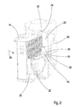
- the outer circumference of the fan 20 surrounds a fan ring 22.
- the fan ring 22 forms a closed ring around the fan 20 and is provided at its end adjacent to the engine 12 with struts 26 which extend radially to the drive shaft 16 back. Between the struts 26 free spaces can be formed or arranged a grid.
- the struts 26 of the fan ring 22 are supported by a bearing 28 in the form of a rolling bearing (eg needle or ball bearings) on the drive shaft 16.
- the bearing 28 secures the fan ring 22 against a radial and against axial movement relative to the drive shaft 16. Since the fan ring 22 is mounted on the drive shaft 16, which also carries the fan 22, so that there are no relative movements between the fan 20 and the fan ring 22 result, and since the fan ring in one piece, in particular made of plastic, and rotationally symmetric and thus can be produced with low tolerances, the radial gap between the fan 20 and the fan ring 22 can be relatively narrow, which is a good efficiency of the fan 20 and a low Noise development possible.
- a fan housing 30 is attached, which covers the outside of the enveloping circle of the fan 20 surfaces of the radiator 14 in a funnel shape and ends at its the fan ring 22 adjacent end annularly with a diameter corresponding to the diameter of the fan ring 22 corresponds at least approximately.
- a decoupling element 32 of inherently elastic material esp. Rubber
- is attached which is pushed onto the fan housing 30 and it encloses U-shaped (see Figure 2).
- a similar decoupling element 34 is attached.
- the decoupling elements 32, 34 are biased against each other. Since the fan ring 22 transmits a force to the fan housing 30, the decoupling elements 32, 34 are compressed to a certain extent. As a result, the fan ring 22nd fixed in the direction of rotation of the fan 20. The sealing effect of the decoupling elements 32, 34 is retained due to their elasticity even when the radiator 14 and with him the fan housing 30 relative to the internal combustion engine 12 and the associated fan ring 22 moves.
Landscapes
- Engineering & Computer Science (AREA)
- Mechanical Engineering (AREA)
- General Engineering & Computer Science (AREA)
- Chemical & Material Sciences (AREA)
- Combustion & Propulsion (AREA)
- Structures Of Non-Positive Displacement Pumps (AREA)
- Cooling, Air Intake And Gas Exhaust, And Fuel Tank Arrangements In Propulsion Units (AREA)
Abstract
Description
Die Erfindung betrifft einen Lüfterzusammenbau mit einem durch eine Antriebswelle mechanisch mit einem Verbrennungsmotor verbindbaren und in Drehung versetzbaren Lüfter und einem den Lüfter in Umfangsrichtung umschließenden, mit dem Verbrennungsmotor mechanisch verbundenen Lüfterring sowie ein Verfahren zu seiner Montage an einem Fahrzeug.The invention relates to a fan assembly comprising a fan which can be mechanically connected to an internal combustion engine by a drive shaft and set in rotation, and a fan ring which surrounds the fan in the circumferential direction and which is mechanically connected to the internal combustion engine, and a method for mounting it on a vehicle.
Die WO 98/037319 A zeigt einen Lüfterzusammenbau für einen Fahrzeugmotor. Der Umfang eines durch den Fahrzeugmotor angetriebenen Lüfters wird von einem Lüfterring umschlossen, der durch mehrere Halterungen am Fahrzeugmotor befestigt ist. Zwischen einem Kühler und dem Lüfterring ist ein Lüftergehäuse angeordnet, das fest mit dem Kühler verbunden ist. Zwischen dem Lüftergehäuse und dem Kühler befindet sich ein Spalt, der durch eine Dichtung aus einem elastischen Material wie Gummi geschlossen wird, um die abdichtende Funktion aufrecht zu erhalten, wenn sich der Motor und der Kühler beim Fahrzeugbetrieb gegenseitig verschieben. Hier wird der Lüfterring durch die Halterungen am Motor fixiert, so dass ein gewisser Aufwand für die Herstellung und Anbringung der Halterungen erforderlich ist.WO 98/037319 A shows a fan assembly for a vehicle engine. The circumference of a fan driven by the vehicle engine is enclosed by a fan ring secured to the vehicle engine by a plurality of brackets. Between a radiator and the fan ring a fan housing is arranged, which is firmly connected to the radiator. Between the fan housing and the radiator is a gap which is closed by a seal of a resilient material such as rubber to maintain the sealing function when the engine and the radiator mutually shift during vehicle operation. Here, the fan ring is fixed by the brackets on the engine, so that a certain effort for the manufacture and attachment of the brackets is required.
In der US 3 794 001 A wird ein anderer Lüfterzusammenbau mit einem vom Verbrennungsmotor angetriebenen Lüfter beschrieben. Der Kühler trägt ein Lüftergehäuse mit einem ringförmigen Fortsatz, in den ein dem Umfang des Lüfters benachbarter Lüfterring eingeschoben ist. Hier sind Relativbewegungen zwischen dem Lüfterring und dem Lüfter möglich, die einen relativ großen Spalt zwischen diesen Elementen erfordern, was den Wirkungsgrad des Lüfters nachteilig beeinflusst.Another fan assembly with a fan driven by the internal combustion engine is described in US Pat. No. 3,794,001 A. The radiator carries a fan housing with an annular extension into which a fan ring adjacent to the circumference of the fan is inserted. Here relative movements between the fan ring and the fan are possible, which require a relatively large gap between these elements, which adversely affects the efficiency of the fan.
Weiterhin sind Lüfterzusammenbauten bekannt, bei denen der Lüfterring fest am Kühler befestigt ist und den elektrisch betriebenen Lüftermotor und den Lüfter trägt (DE 42 44 039 A). Diese Anordnungen eignen sich insbesondere für kleinere Kühlleistungen, da der elektrische Antrieb des Lüfters hohen Aufwand erfordert und mit Verlust behaftet ist.Furthermore, fan assemblies are known in which the fan ring is fixedly secured to the radiator and the electric operated fan motor and the fan carries (DE 42 44 039 A). These arrangements are particularly suitable for smaller cooling capacities, since the electric drive of the fan requires great effort and is associated with loss.
Die der Erfindung zu Grunde liegende Aufgabe wird darin gesehen, einen einfach und preisgünstig herstellbaren Lüfterzusammenbau bereitzustellen.The object underlying the invention is seen to provide a simple and inexpensive to produce fan assembly.
Diese Aufgabe wird erfindungsgemäß durch die Lehren der Patentansprüche 1 und 8 gelöst, wobei in den weiteren Patentansprüchen Merkmale aufgeführt sind, die die Lösung in vorteilhafter Weise weiterentwickeln.This object is achieved by the teachings of claims 1 and 8, which are listed in the other claims features that further develop the solution in an advantageous manner.
Es wird vorgeschlagen, den Lüfterring mit einer drehbaren Lagerung an der Antriebswelle des vom Verbrennungsmotor mechanisch antreibbaren Lüfters zu befestigen. Dadurch erübrigen sich separate Halterungen zur Befestigung des Lüfterrings am Verbrennungsmotor. Weiterhin kann durch die Befestigung des Lüfterrings am Verbrennungsmotor ein sehr enges Spaltmaß zwischen dem Lüfter und dem Lüfterring eingehalten werden, da auch bei einer Vibration des Verbrennungsmotors keine Relativbewegung zwischen dem Lüfter und dem Lüfterring stattfindet.It is proposed to fasten the fan ring with a rotatable mounting on the drive shaft of the mechanically drivable fan of the internal combustion engine. This eliminates the need separate brackets for mounting the fan ring on the engine. Furthermore, a very narrow gap between the fan and the fan ring can be maintained by attaching the fan ring on the engine, since even with a vibration of the engine, no relative movement between the fan and the fan ring takes place.
Während die Lagerung den Lüfterring bezüglich der Längsachse der Antriebswelle in axialer und radialer Richtung abstützt, kann eine Fixierung des Lüfterrings in Umfangsrichtung durch ein indirekt mit dem Verbrennungsmotor verbundenes Lüftergehäuse erfolgen, an dem der Lüfterring mit einer Vorspannung anliegt. Die sich ergebende kraftschlüssige Verbindung hält den Lüfterring in der Drehrichtung des Lüfters fest. Auf diese Weise erübrigen sich weitere Halterungen zum Fixieren des Lüfterrings in seiner Umfangsrichtung. In einer bevorzugten Ausführungsform ist das Lüftergehäuse an einem Kühler angebracht, der im Betrieb mit von Lüfter transportierter Luft durchströmt wird. Es wäre andererseits aber auch denkbar, den Lüfterring durch einfache Verbindungsmittel mit dem Verbrennungsmotor oder einem damit verbundenen Element zu verbinden, um den Lüfterring in seiner Umfangsrichtung festzusetzen. So könnte er eine überstehende Nase aufweisen, die in eine Öffnung am Rahmen des Fahrzeugs eingreift.While the bearing supports the fan ring with respect to the longitudinal axis of the drive shaft in the axial and radial directions, a fixing of the fan ring in the circumferential direction can be effected by a fan housing connected indirectly to the internal combustion engine, against which the fan ring bears with a bias voltage. The resulting frictional connection holds the fan ring in the direction of rotation of the fan. In this way, unnecessary additional brackets for fixing the fan ring in its circumferential direction. In a preferred embodiment, the fan housing is attached to a radiator that is in operation flows through with air transported by fan. On the other hand, it would also be conceivable to connect the fan ring by simple connection means to the internal combustion engine or an element connected to it in order to fix the fan ring in its circumferential direction. So he could have a protruding nose, which engages in an opening on the frame of the vehicle.
Sich zwischen dem (durch die Lagerung und die Antriebswelle mit dem Verbrennungsmotor verbundenen) Lüfterring und dem (mit dem Kühler verbundenen) Lüftergehäuse möglicherweise ergebende Relativbewegungen werden vorzugsweise durch geeignete, flexible Entkopplungselemente aufgenommen, die zwischen dem Lüfterring und dem Lüftergehäuse angeordnet sind.Relative movements possibly arising between the fan ring (connected by the bearing and the drive shaft to the engine) and the fan housing (connected to the radiator) are preferably accommodated by suitable, flexible decoupling elements arranged between the fan ring and the fan housing.
Durch die beschriebene Befestigung kann die Lüfterhaube als rotationssymmetrisches sowie einteiliges und somit preiswertes, da keine zusätzlichen Arbeitsschritte zur Montage erforderndes Element hergestellt werden.As a result of the fastening described, the fan cowl can be produced as rotationally symmetrical as well as one-piece and thus inexpensive, since no additional work steps are required for mounting the element.
Die erfindungsgemäße Gestaltung des Lüfterzusammenbaus ermöglicht es, zunächst eine Baugruppe zu fertigen, die sich aus der Antriebswelle, dem Lüfter und dem durch die Lagerung mit der Antriebswelle verbundenen Lüfterring zusammensetzt. Diese Baugruppe wird dann in einen Zwischenraum zwischen einem Kühler mit einem Lüftergehäuse und einem Verbrennungsmotor eingefügt, so dass der Lüfterring durch den Kontakt mit dem Lüftergehäuse in seiner Umfangsrichtung fixiert wird. Die Antriebswelle wird mit dem Verbrennungsmotor verbunden.The inventive design of the fan assembly makes it possible to first manufacture an assembly that is composed of the drive shaft, the fan and the connected by the bearing with the drive shaft fan ring. This assembly is then inserted into a gap between a radiator with a fan housing and an internal combustion engine, so that the fan ring is fixed in its circumferential direction by the contact with the fan housing. The drive shaft is connected to the engine.
In den Zeichnungen ist ein nachfolgend näher beschriebenes Ausführungsbeispiel der Erfindung dargestellt. Es zeigt:
- Fig. 1
- einen schematischen seitlichen Schnitt durch einen erfindungsgemäßen Lüfterzusammenbau, und
- Fig. 2
- eine perspektivische Ansicht des Lüfterzusammenbaus.
- Fig. 1
- a schematic lateral section through a fan assembly according to the invention, and
- Fig. 2
- a perspective view of the fan assembly.
Auf einem Rahmen 10 eines insbesondere landwirtschaftlichen Fahrzeugs, beispielsweise eines Traktors, Teleskopladers oder einer selbstfahrenden Erntemaschine, ist ein Verbrennungsmotor 12 befestigt, vorzugsweise über Gummilager (nicht eingezeichnet). Der Rahmen trägt auch einen Kühler 14, der zur Kühlung des Verbrennungsmotors 12 und/oder anderer Aggregate des Fahrzeugs dient. Der Kühler 14 kann Öl oder Wasser als Kühlflüssigkeit verwenden. Anstelle des Kühlers 14 oder stromab oder stromauf davon oder in seitlicher oder vertikaler Richtung neben dem bzw. oberhalb des Kühler(s) 14 könnte auch ein Ladeluftkühler für einen Turbolader des Verbrennungsmotors 12 oder eine Kühleinrichtung für eine Klimaanlage oder ein Kühler für einen Hydraulikkreis des Fahrzeugs o. ä. vorgesehen sein.On a
Der Verbrennungsmotor 12 weist eine Abtriebswelle 38 auf, die sich in Richtung auf den Kühler 14 zu erstreckt. Zur Verbindung einer Antriebswelle 16 mit der Abtriebswelle 38 des Verbrennungsmotors 12 ist eine Klemmmutter 36 vorgesehen. Die Abtriebswelle 38 (oder eine weitere, nicht eingezeichnete Abtriebswelle des Verbrennungsmotors 12) dient zum Antrieb der angetriebenen Elemente des Fahrzeugs, z. B. für den Fahrantrieb, eine Zapfwelle oder Erntegutbearbeitungseinrichtungen. Auf der Antriebswelle 16 ist eine schaltbare Kupplung 18 angeordnet, um deren Umfang ein Lüfter 20 mit Schaufeln zur Luftförderung angeordnet ist. Die Kupplung 18 wird elektrisch oder hydraulisch oder thermisch betätigt und dient zum Ein- und Ausschalten oder zur stufigen oder stufenlosen Vorgabe der Drehzahl des Lüfters 20. Der Lüfter 20 stellt bei laufendem Verbrennungsmotor 12 und eingeschalteter Kupplung 18 einen Luftstrom in Richtung des Pfeils 24 durch den Kühler 14 und zum Verbrennungsmotor 12 hin bereit.The
Den äußeren Umfang des Lüfters 20 umrundet ein Lüfterring 22.The outer circumference of the
Der Lüfterring 22 bildet einen geschlossenen Ring um den Lüfter 20 und ist an seinem dem Verbrennungsmotor 12 benachbarten Ende mit Streben 26 ausgestattet, die sich radial zur Antriebswelle 16 hin erstrecken. Zwischen den Streben 26 können Freiräume gebildet oder ein Gitter angeordnet sein.The
Die Streben 26 des Lüfterrings 22 sind durch eine Lagerung 28 in Form eines Wälzlagers (z. B. Nadel- oder Kugellager) an der Antriebswelle 16 abgestützt. Die Lagerung 28 sichert den Lüfterring 22 gegen eine radiale und gegen eine axiale Bewegung gegenüber der Antriebswelle 16. Da der Lüfterring 22 an der Antriebswelle 16 gelagert ist, die auch den Lüfter 22 trägt, so dass sich keine Relativbewegungen zwischen dem Lüfter 20 und dem Lüfterring 22 ergeben, und da der Lüfterring einteilig, insbesondere aus Kunststoff, und rotationssymmetrisch und demnach mit geringen Toleranzen herstellbar ist, kann der radiale Spalt zwischen dem Lüfter 20 und dem Lüfterring 22 relativ eng gewählt werden, was einen guten Wirkungsgrad des Lüfters 20 und eine geringe Geräuschentwicklung ermöglicht.The
An der dem Lüfter 20 zugewandten Seite des Kühlers 14 ist ein Lüftergehäuse 30 befestigt, das die außerhalb des Hüllkreises des Lüfters 20 liegenden Flächen des Kühlers 14 trichterförmig abdeckt und an seiner dem Lüfterring 22 benachbarten Stirnseite ringförmig mit einem Durchmesser endet, der dem Durchmesser des Lüfterrings 22 zumindest näherungsweise entspricht. An dieser Stirnseite des Lüftergehäuses 30 ist ein Entkopplungselement 32 aus in sich elastischem Material (insb. Gummi) angebracht, das auf das Lüftergehäuse 30 aufgeschoben ist und es U-förmig umschließt (s. Figur 2). An der benachbarten Stirnseite des Lüfterrings 22 ist ein gleichartiges Entkopplungselement 34 befestigt.At the
Die Entkopplungselemente 32, 34 liegen aneinander vorgespannt an. Da der Lüfterring 22 eine Kraft auf das Lüftergehäuse 30 überträgt, sind die Entkopplungselemente 32, 34 in einem bestimmten Maße zusammengepresst. Dadurch wird der Lüfterring 22 in der Drehrichtung des Lüfters 20 fixiert. Die Dichtwirkung der Entkopplungselemente 32, 34 bleibt auf Grund ihrer Elastizität auch dann erhalten, wenn sich der Kühler 14 und mit ihm das Lüftergehäuse 30 gegenüber dem Verbrennungsmotor 12 und dem damit verbundenen Lüfterring 22 bewegt.The
Anhand der Figuren ist erkennbar, dass sich eine aus der Kupplung 18, dem Lüfter 20 und dem Lüfterring 22 bestehende Baugruppe vormontieren und dann als komplette Einheit in das Fahrzeug einbauen lässt. Es sind keine zusätzlichen Halter oder dgl. zur Befestigung des Lüfterrings am Verbrennungsmotor 12 oder am Lüftergehäuse 30 notwendig.It can be seen from the figures that a subassembly consisting of the
Claims (8)
Applications Claiming Priority (1)
| Application Number | Priority Date | Filing Date | Title |
|---|---|---|---|
| DE102004057153A DE102004057153A1 (en) | 2004-11-26 | 2004-11-26 | fan assembly |
Publications (2)
| Publication Number | Publication Date |
|---|---|
| EP1662111A1 true EP1662111A1 (en) | 2006-05-31 |
| EP1662111B1 EP1662111B1 (en) | 2007-12-12 |
Family
ID=35783418
Family Applications (1)
| Application Number | Title | Priority Date | Filing Date |
|---|---|---|---|
| EP05111024A Active EP1662111B1 (en) | 2004-11-26 | 2005-11-21 | Fan assembly |
Country Status (4)
| Country | Link |
|---|---|
| US (1) | US7322319B2 (en) |
| EP (1) | EP1662111B1 (en) |
| AT (1) | ATE380929T1 (en) |
| DE (2) | DE102004057153A1 (en) |
Cited By (2)
| Publication number | Priority date | Publication date | Assignee | Title |
|---|---|---|---|---|
| WO2008022739A1 (en) * | 2006-08-19 | 2008-02-28 | Daimler Ag | Air conduction system for cooling an internal combustion engine |
| EP2006542A1 (en) * | 2007-06-19 | 2008-12-24 | Schneider Druckluft GmbH | Compressor device with sealing assembly |
Families Citing this family (4)
| Publication number | Priority date | Publication date | Assignee | Title |
|---|---|---|---|---|
| US7165515B2 (en) * | 2004-08-30 | 2007-01-23 | International Truck Intellectual Property Company, Llc | Engine cooling fan shroud |
| US20060081353A1 (en) * | 2004-10-19 | 2006-04-20 | Inniger Steven W | Split access fan shroud |
| US20070277752A1 (en) * | 2006-06-05 | 2007-12-06 | Deere & Company, A Delaware Corporation | Shroud assembly |
| CN108513553B (en) * | 2016-12-28 | 2022-03-29 | 株式会社小松制作所 | Working vehicle |
Citations (5)
| Publication number | Priority date | Publication date | Assignee | Title |
|---|---|---|---|---|
| US3794001A (en) | 1973-03-02 | 1974-02-26 | Ford Motor Co | Variable tip clearance engine cooling fan shroud |
| EP0515785A1 (en) * | 1991-05-27 | 1992-12-02 | Behr GmbH & Co. | Fan drive for the radiator of an automotive vehicle |
| DE4244039A1 (en) | 1992-12-24 | 1994-07-07 | Behr Gmbh & Co | Cooling module for goods vehicle combustion engine |
| JPH0988604A (en) * | 1995-09-29 | 1997-03-31 | Sumitomo Constr Mach Co Ltd | Engine cooling device |
| WO1998037319A1 (en) | 1997-02-21 | 1998-08-27 | Scania Cv Aktiebolag (Publ) | Fan ring seal |
Family Cites Families (10)
| Publication number | Priority date | Publication date | Assignee | Title |
|---|---|---|---|---|
| JPS6047453B2 (en) * | 1978-01-13 | 1985-10-22 | トヨタ自動車株式会社 | Internal combustion engine cooling system |
| AT379435B (en) | 1980-08-05 | 1986-01-10 | List Hans | AXIAL FAN |
| US4522160A (en) * | 1984-01-23 | 1985-06-11 | J. I. Case Company | Fan-shroud structure |
| DE4015259A1 (en) | 1990-05-12 | 1991-11-14 | Behr Gmbh & Co | Ventilator casing for coolant blower in motor vehicle - has roller bearing between belt-driven pulley and tightly enclosed fan secured against rotation w.r.t. engine |
| JP2928659B2 (en) * | 1991-05-31 | 1999-08-03 | エヌティエヌ株式会社 | Outer ring for anti-vibration constant velocity joint and anti-vibration constant velocity joint |
| US5183382A (en) * | 1991-09-03 | 1993-02-02 | Caterpillar Inc. | Low noise rotating fan and shroud assembly |
| JPH084529A (en) * | 1994-06-23 | 1996-01-09 | Aisin Chem Co Ltd | Cooling fan shroud device |
| DE19526286A1 (en) * | 1995-07-19 | 1997-01-23 | Behr Gmbh & Co | Heat exchanger |
| JPH09264138A (en) | 1996-03-29 | 1997-10-07 | Nissan Diesel Motor Co Ltd | Fan shroud device |
| JP2002122023A (en) * | 2000-10-16 | 2002-04-26 | Nissan Diesel Motor Co Ltd | Cooling fan shroud device |
-
2004
- 2004-11-26 DE DE102004057153A patent/DE102004057153A1/en not_active Withdrawn
-
2005
- 2005-11-15 US US11/274,725 patent/US7322319B2/en active Active
- 2005-11-21 EP EP05111024A patent/EP1662111B1/en active Active
- 2005-11-21 DE DE502005002209T patent/DE502005002209D1/en active Active
- 2005-11-21 AT AT05111024T patent/ATE380929T1/en not_active IP Right Cessation
Patent Citations (5)
| Publication number | Priority date | Publication date | Assignee | Title |
|---|---|---|---|---|
| US3794001A (en) | 1973-03-02 | 1974-02-26 | Ford Motor Co | Variable tip clearance engine cooling fan shroud |
| EP0515785A1 (en) * | 1991-05-27 | 1992-12-02 | Behr GmbH & Co. | Fan drive for the radiator of an automotive vehicle |
| DE4244039A1 (en) | 1992-12-24 | 1994-07-07 | Behr Gmbh & Co | Cooling module for goods vehicle combustion engine |
| JPH0988604A (en) * | 1995-09-29 | 1997-03-31 | Sumitomo Constr Mach Co Ltd | Engine cooling device |
| WO1998037319A1 (en) | 1997-02-21 | 1998-08-27 | Scania Cv Aktiebolag (Publ) | Fan ring seal |
Non-Patent Citations (1)
| Title |
|---|
| PATENT ABSTRACTS OF JAPAN vol. 1997, no. 07 31 July 1997 (1997-07-31) * |
Cited By (2)
| Publication number | Priority date | Publication date | Assignee | Title |
|---|---|---|---|---|
| WO2008022739A1 (en) * | 2006-08-19 | 2008-02-28 | Daimler Ag | Air conduction system for cooling an internal combustion engine |
| EP2006542A1 (en) * | 2007-06-19 | 2008-12-24 | Schneider Druckluft GmbH | Compressor device with sealing assembly |
Also Published As
| Publication number | Publication date |
|---|---|
| DE502005002209D1 (en) | 2008-01-24 |
| ATE380929T1 (en) | 2007-12-15 |
| US7322319B2 (en) | 2008-01-29 |
| DE102004057153A1 (en) | 2006-06-08 |
| EP1662111B1 (en) | 2007-12-12 |
| US20060112909A1 (en) | 2006-06-01 |
Similar Documents
| Publication | Publication Date | Title |
|---|---|---|
| EP1662111B1 (en) | Fan assembly | |
| DE102011107088A1 (en) | Flap device, particularly exhaust flap device for selectively closing exhaust gas path in exhaust system of motor vehicle, has flap rotatably mounted around flap axis, actuator, particularly electrical actuator for rotation of flap | |
| DE102010036933A1 (en) | Method for producing a stator for an electric water pump | |
| DE102010036935A1 (en) | Electric water pump | |
| DE102006042340A1 (en) | Electric motor, in particular for a windshield wiper drive of a motor vehicle with an improved recording of the bearing of the armature shaft | |
| DE102018205471A1 (en) | Storage for a hybrid module | |
| DE102006047393A1 (en) | Cooling fan and method for producing a cooling fan | |
| EP2829762A2 (en) | Integrated switchable shaft bearing | |
| EP1876407A1 (en) | Cooling device for a motor vehicle | |
| DE102011083056A1 (en) | Radabschaltsystem | |
| DE3036771T1 (en) | CENTER BEARING BRACKET | |
| DE102009055614B4 (en) | Turbocharger with a plastic compressor housing | |
| DE102009014027A1 (en) | Device for transferring torque from a combustion engine to a secondary unit, especially the compressor of an air conditioning unit of a vehicle, comprises a hub and a plastic pulley rotatably arranged on the housing of the secondary unit | |
| DE102011102018A1 (en) | Valve device used in gas exhaust system for motor vehicle, has valve connected with actuator by connectors and resilient coupling that is formed of sleeve-shape and provided with bellows | |
| EP3401545B1 (en) | Side-channel blower and centrifugal pump driven by a common motor, wherein the pump is driven via a magnetic transmission | |
| DE102010020102A1 (en) | Device for controlling an exhaust valve of an internal combustion engine | |
| EP0515785A1 (en) | Fan drive for the radiator of an automotive vehicle | |
| DE102016201015A1 (en) | Adjustment device for a throttle valve | |
| DE102015211856A1 (en) | Viscose coupling | |
| DE10353431B4 (en) | Shaft passage on an air intake duct system | |
| EP1146308A2 (en) | Heat exchanger with housing comprising a cover | |
| DE102018217226A1 (en) | Exhaust gas turbocharger with improved cooling system | |
| DE102016201020A1 (en) | Adjustment device for a throttle valve | |
| WO2008122652A1 (en) | Constructional unit and fresh air system | |
| DE102014202696B4 (en) | Device for transmitting torque in a range extender |
Legal Events
| Date | Code | Title | Description |
|---|---|---|---|
| PUAI | Public reference made under article 153(3) epc to a published international application that has entered the european phase |
Free format text: ORIGINAL CODE: 0009012 |
|
| AK | Designated contracting states |
Kind code of ref document: A1 Designated state(s): AT BE BG CH CY CZ DE DK EE ES FI FR GB GR HU IE IS IT LI LT LU LV MC NL PL PT RO SE SI SK TR |
|
| AX | Request for extension of the european patent |
Extension state: AL BA HR MK YU |
|
| 17P | Request for examination filed |
Effective date: 20061130 |
|
| AKX | Designation fees paid |
Designated state(s): AT BE BG CH CY CZ DE DK EE ES FI FR GB GR HU IE IS IT LI LT LU LV MC NL PL PT RO SE SI SK TR |
|
| 17Q | First examination report despatched |
Effective date: 20070124 |
|
| GRAP | Despatch of communication of intention to grant a patent |
Free format text: ORIGINAL CODE: EPIDOSNIGR1 |
|
| GRAS | Grant fee paid |
Free format text: ORIGINAL CODE: EPIDOSNIGR3 |
|
| GRAA | (expected) grant |
Free format text: ORIGINAL CODE: 0009210 |
|
| AK | Designated contracting states |
Kind code of ref document: B1 Designated state(s): AT BE BG CH CY CZ DE DK EE ES FI FR GB GR HU IE IS IT LI LT LU LV MC NL PL PT RO SE SI SK TR |
|
| REG | Reference to a national code |
Ref country code: GB Ref legal event code: FG4D Free format text: NOT ENGLISH |
|
| REG | Reference to a national code |
Ref country code: CH Ref legal event code: EP |
|
| REG | Reference to a national code |
Ref country code: IE Ref legal event code: FG4D Free format text: LANGUAGE OF EP DOCUMENT: GERMAN |
|
| REF | Corresponds to: |
Ref document number: 502005002209 Country of ref document: DE Date of ref document: 20080124 Kind code of ref document: P |
|
| GBT | Gb: translation of ep patent filed (gb section 77(6)(a)/1977) |
Effective date: 20080206 |
|
| PG25 | Lapsed in a contracting state [announced via postgrant information from national office to epo] |
Ref country code: SE Free format text: LAPSE BECAUSE OF FAILURE TO SUBMIT A TRANSLATION OF THE DESCRIPTION OR TO PAY THE FEE WITHIN THE PRESCRIBED TIME-LIMIT Effective date: 20080312 |
|
| PG25 | Lapsed in a contracting state [announced via postgrant information from national office to epo] |
Ref country code: FI Free format text: LAPSE BECAUSE OF FAILURE TO SUBMIT A TRANSLATION OF THE DESCRIPTION OR TO PAY THE FEE WITHIN THE PRESCRIBED TIME-LIMIT Effective date: 20071212 Ref country code: LV Free format text: LAPSE BECAUSE OF FAILURE TO SUBMIT A TRANSLATION OF THE DESCRIPTION OR TO PAY THE FEE WITHIN THE PRESCRIBED TIME-LIMIT Effective date: 20071212 Ref country code: LT Free format text: LAPSE BECAUSE OF FAILURE TO SUBMIT A TRANSLATION OF THE DESCRIPTION OR TO PAY THE FEE WITHIN THE PRESCRIBED TIME-LIMIT Effective date: 20071212 Ref country code: SI Free format text: LAPSE BECAUSE OF FAILURE TO SUBMIT A TRANSLATION OF THE DESCRIPTION OR TO PAY THE FEE WITHIN THE PRESCRIBED TIME-LIMIT Effective date: 20071212 Ref country code: NL Free format text: LAPSE BECAUSE OF FAILURE TO SUBMIT A TRANSLATION OF THE DESCRIPTION OR TO PAY THE FEE WITHIN THE PRESCRIBED TIME-LIMIT Effective date: 20071212 Ref country code: PL Free format text: LAPSE BECAUSE OF FAILURE TO SUBMIT A TRANSLATION OF THE DESCRIPTION OR TO PAY THE FEE WITHIN THE PRESCRIBED TIME-LIMIT Effective date: 20071212 |
|
| NLV1 | Nl: lapsed or annulled due to failure to fulfill the requirements of art. 29p and 29m of the patents act | ||
| PG25 | Lapsed in a contracting state [announced via postgrant information from national office to epo] |
Ref country code: CZ Free format text: LAPSE BECAUSE OF FAILURE TO SUBMIT A TRANSLATION OF THE DESCRIPTION OR TO PAY THE FEE WITHIN THE PRESCRIBED TIME-LIMIT Effective date: 20071212 Ref country code: IS Free format text: LAPSE BECAUSE OF FAILURE TO SUBMIT A TRANSLATION OF THE DESCRIPTION OR TO PAY THE FEE WITHIN THE PRESCRIBED TIME-LIMIT Effective date: 20080412 Ref country code: ES Free format text: LAPSE BECAUSE OF FAILURE TO SUBMIT A TRANSLATION OF THE DESCRIPTION OR TO PAY THE FEE WITHIN THE PRESCRIBED TIME-LIMIT Effective date: 20080323 |
|
| ET | Fr: translation filed | ||
| PG25 | Lapsed in a contracting state [announced via postgrant information from national office to epo] |
Ref country code: SK Free format text: LAPSE BECAUSE OF FAILURE TO SUBMIT A TRANSLATION OF THE DESCRIPTION OR TO PAY THE FEE WITHIN THE PRESCRIBED TIME-LIMIT Effective date: 20071212 Ref country code: RO Free format text: LAPSE BECAUSE OF FAILURE TO SUBMIT A TRANSLATION OF THE DESCRIPTION OR TO PAY THE FEE WITHIN THE PRESCRIBED TIME-LIMIT Effective date: 20071212 |
|
| PG25 | Lapsed in a contracting state [announced via postgrant information from national office to epo] |
Ref country code: PT Free format text: LAPSE BECAUSE OF FAILURE TO SUBMIT A TRANSLATION OF THE DESCRIPTION OR TO PAY THE FEE WITHIN THE PRESCRIBED TIME-LIMIT Effective date: 20080512 |
|
| REG | Reference to a national code |
Ref country code: IE Ref legal event code: FD4D |
|
| PLBE | No opposition filed within time limit |
Free format text: ORIGINAL CODE: 0009261 |
|
| STAA | Information on the status of an ep patent application or granted ep patent |
Free format text: STATUS: NO OPPOSITION FILED WITHIN TIME LIMIT |
|
| PG25 | Lapsed in a contracting state [announced via postgrant information from national office to epo] |
Ref country code: DK Free format text: LAPSE BECAUSE OF FAILURE TO SUBMIT A TRANSLATION OF THE DESCRIPTION OR TO PAY THE FEE WITHIN THE PRESCRIBED TIME-LIMIT Effective date: 20071212 Ref country code: IE Free format text: LAPSE BECAUSE OF FAILURE TO SUBMIT A TRANSLATION OF THE DESCRIPTION OR TO PAY THE FEE WITHIN THE PRESCRIBED TIME-LIMIT Effective date: 20071212 |
|
| 26N | No opposition filed |
Effective date: 20080915 |
|
| PG25 | Lapsed in a contracting state [announced via postgrant information from national office to epo] |
Ref country code: GR Free format text: LAPSE BECAUSE OF FAILURE TO SUBMIT A TRANSLATION OF THE DESCRIPTION OR TO PAY THE FEE WITHIN THE PRESCRIBED TIME-LIMIT Effective date: 20080313 |
|
| PG25 | Lapsed in a contracting state [announced via postgrant information from national office to epo] |
Ref country code: EE Free format text: LAPSE BECAUSE OF FAILURE TO SUBMIT A TRANSLATION OF THE DESCRIPTION OR TO PAY THE FEE WITHIN THE PRESCRIBED TIME-LIMIT Effective date: 20071212 Ref country code: BG Free format text: LAPSE BECAUSE OF FAILURE TO SUBMIT A TRANSLATION OF THE DESCRIPTION OR TO PAY THE FEE WITHIN THE PRESCRIBED TIME-LIMIT Effective date: 20080312 |
|
| BERE | Be: lapsed |
Owner name: DEERE & CY Effective date: 20081130 |
|
| PG25 | Lapsed in a contracting state [announced via postgrant information from national office to epo] |
Ref country code: MC Free format text: LAPSE BECAUSE OF NON-PAYMENT OF DUE FEES Effective date: 20081130 |
|
| PG25 | Lapsed in a contracting state [announced via postgrant information from national office to epo] |
Ref country code: CY Free format text: LAPSE BECAUSE OF FAILURE TO SUBMIT A TRANSLATION OF THE DESCRIPTION OR TO PAY THE FEE WITHIN THE PRESCRIBED TIME-LIMIT Effective date: 20071212 |
|
| PG25 | Lapsed in a contracting state [announced via postgrant information from national office to epo] |
Ref country code: BE Free format text: LAPSE BECAUSE OF NON-PAYMENT OF DUE FEES Effective date: 20081130 |
|
| PG25 | Lapsed in a contracting state [announced via postgrant information from national office to epo] |
Ref country code: AT Free format text: LAPSE BECAUSE OF NON-PAYMENT OF DUE FEES Effective date: 20081121 |
|
| REG | Reference to a national code |
Ref country code: CH Ref legal event code: PL |
|
| PG25 | Lapsed in a contracting state [announced via postgrant information from national office to epo] |
Ref country code: HU Free format text: LAPSE BECAUSE OF FAILURE TO SUBMIT A TRANSLATION OF THE DESCRIPTION OR TO PAY THE FEE WITHIN THE PRESCRIBED TIME-LIMIT Effective date: 20080613 Ref country code: LU Free format text: LAPSE BECAUSE OF NON-PAYMENT OF DUE FEES Effective date: 20081121 |
|
| PG25 | Lapsed in a contracting state [announced via postgrant information from national office to epo] |
Ref country code: TR Free format text: LAPSE BECAUSE OF FAILURE TO SUBMIT A TRANSLATION OF THE DESCRIPTION OR TO PAY THE FEE WITHIN THE PRESCRIBED TIME-LIMIT Effective date: 20071212 |
|
| PG25 | Lapsed in a contracting state [announced via postgrant information from national office to epo] |
Ref country code: LI Free format text: LAPSE BECAUSE OF NON-PAYMENT OF DUE FEES Effective date: 20091130 Ref country code: CH Free format text: LAPSE BECAUSE OF NON-PAYMENT OF DUE FEES Effective date: 20091130 |
|
| REG | Reference to a national code |
Ref country code: FR Ref legal event code: PLFP Year of fee payment: 11 |
|
| REG | Reference to a national code |
Ref country code: FR Ref legal event code: PLFP Year of fee payment: 12 |
|
| REG | Reference to a national code |
Ref country code: FR Ref legal event code: PLFP Year of fee payment: 13 |
|
| PGFP | Annual fee paid to national office [announced via postgrant information from national office to epo] |
Ref country code: GB Payment date: 20231127 Year of fee payment: 19 |
|
| PGFP | Annual fee paid to national office [announced via postgrant information from national office to epo] |
Ref country code: IT Payment date: 20231122 Year of fee payment: 19 Ref country code: FR Payment date: 20231127 Year of fee payment: 19 Ref country code: DE Payment date: 20231019 Year of fee payment: 19 |