EP1662019A1 - Method of producing defect free deposited titanium alloys - Google Patents
Method of producing defect free deposited titanium alloys Download PDFInfo
- Publication number
- EP1662019A1 EP1662019A1 EP05255509A EP05255509A EP1662019A1 EP 1662019 A1 EP1662019 A1 EP 1662019A1 EP 05255509 A EP05255509 A EP 05255509A EP 05255509 A EP05255509 A EP 05255509A EP 1662019 A1 EP1662019 A1 EP 1662019A1
- Authority
- EP
- European Patent Office
- Prior art keywords
- heating
- transus
- temperature
- equilibrium
- essentially
- Prior art date
- Legal status (The legal status is an assumption and is not a legal conclusion. Google has not performed a legal analysis and makes no representation as to the accuracy of the status listed.)
- Granted
Links
Images

Classifications
-
- C—CHEMISTRY; METALLURGY
- C22—METALLURGY; FERROUS OR NON-FERROUS ALLOYS; TREATMENT OF ALLOYS OR NON-FERROUS METALS
- C22F—CHANGING THE PHYSICAL STRUCTURE OF NON-FERROUS METALS AND NON-FERROUS ALLOYS
- C22F1/00—Changing the physical structure of non-ferrous metals or alloys by heat treatment or by hot or cold working
- C22F1/16—Changing the physical structure of non-ferrous metals or alloys by heat treatment or by hot or cold working of other metals or alloys based thereon
- C22F1/18—High-melting or refractory metals or alloys based thereon
- C22F1/183—High-melting or refractory metals or alloys based thereon of titanium or alloys based thereon
-
- C—CHEMISTRY; METALLURGY
- C23—COATING METALLIC MATERIAL; COATING MATERIAL WITH METALLIC MATERIAL; CHEMICAL SURFACE TREATMENT; DIFFUSION TREATMENT OF METALLIC MATERIAL; COATING BY VACUUM EVAPORATION, BY SPUTTERING, BY ION IMPLANTATION OR BY CHEMICAL VAPOUR DEPOSITION, IN GENERAL; INHIBITING CORROSION OF METALLIC MATERIAL OR INCRUSTATION IN GENERAL
- C23C—COATING METALLIC MATERIAL; COATING MATERIAL WITH METALLIC MATERIAL; SURFACE TREATMENT OF METALLIC MATERIAL BY DIFFUSION INTO THE SURFACE, BY CHEMICAL CONVERSION OR SUBSTITUTION; COATING BY VACUUM EVAPORATION, BY SPUTTERING, BY ION IMPLANTATION OR BY CHEMICAL VAPOUR DEPOSITION, IN GENERAL
- C23C14/00—Coating by vacuum evaporation, by sputtering or by ion implantation of the coating forming material
- C23C14/06—Coating by vacuum evaporation, by sputtering or by ion implantation of the coating forming material characterised by the coating material
- C23C14/14—Metallic material, boron or silicon
- C23C14/16—Metallic material, boron or silicon on metallic substrates or on substrates of boron or silicon
-
- C—CHEMISTRY; METALLURGY
- C23—COATING METALLIC MATERIAL; COATING MATERIAL WITH METALLIC MATERIAL; CHEMICAL SURFACE TREATMENT; DIFFUSION TREATMENT OF METALLIC MATERIAL; COATING BY VACUUM EVAPORATION, BY SPUTTERING, BY ION IMPLANTATION OR BY CHEMICAL VAPOUR DEPOSITION, IN GENERAL; INHIBITING CORROSION OF METALLIC MATERIAL OR INCRUSTATION IN GENERAL
- C23C—COATING METALLIC MATERIAL; COATING MATERIAL WITH METALLIC MATERIAL; SURFACE TREATMENT OF METALLIC MATERIAL BY DIFFUSION INTO THE SURFACE, BY CHEMICAL CONVERSION OR SUBSTITUTION; COATING BY VACUUM EVAPORATION, BY SPUTTERING, BY ION IMPLANTATION OR BY CHEMICAL VAPOUR DEPOSITION, IN GENERAL
- C23C14/00—Coating by vacuum evaporation, by sputtering or by ion implantation of the coating forming material
- C23C14/58—After-treatment
- C23C14/5806—Thermal treatment
-
- Y—GENERAL TAGGING OF NEW TECHNOLOGICAL DEVELOPMENTS; GENERAL TAGGING OF CROSS-SECTIONAL TECHNOLOGIES SPANNING OVER SEVERAL SECTIONS OF THE IPC; TECHNICAL SUBJECTS COVERED BY FORMER USPC CROSS-REFERENCE ART COLLECTIONS [XRACs] AND DIGESTS
- Y10—TECHNICAL SUBJECTS COVERED BY FORMER USPC
- Y10T—TECHNICAL SUBJECTS COVERED BY FORMER US CLASSIFICATION
- Y10T428/00—Stock material or miscellaneous articles
- Y10T428/12—All metal or with adjacent metals
- Y10T428/12493—Composite; i.e., plural, adjacent, spatially distinct metal components [e.g., layers, joint, etc.]
- Y10T428/12771—Transition metal-base component
- Y10T428/12806—Refractory [Group IVB, VB, or VIB] metal-base component
Definitions
- the invention relates to deposition of Ti-based materials. More particularly, the invention relates to addressing deposition defects.
- EBPVD electron beam physical vapor deposition
- Such techniques may be used in the aerospace industry for the repair or remanufacture of damaged or worn parts such as gas turbine engine components (e.g., blades, vanes, seals, and the like).
- Deposition defects potentially compromise the condensate integrity.
- One group of such defects arises when a droplet of material is spattered onto the substrate or the accumulating condensate.
- the melt pool may contain additives not intended to vaporize and accumulate in the condensate.
- U.S. Patent No. 5,474,809 discloses use of refractory elements in the melt pool.
- One aspect of the invention involves a method for treating a deposited titanium-base material from an initial condition to a treated condition.
- the material is heated from a first temperature to a second temperature.
- the first temperature is below an equilibrium ⁇ transus.
- the second temperature is above the equilibrium ⁇ transus.
- the heating includes a portion at a rate in excess of 5°C/s.
- the material is cooled from the second temperature to a third temperature below the equilibrium ⁇ transus.
- the heating may be to a peak at least 10°C above a non-equilibrium ⁇ transus.
- the material may be above the equilibrium ⁇ transus for a brief period (e.g., no more than 2.0 seconds).
- the heating and cooling may have sufficient rates to maintain a characteristic grain size of at least a matrix of the material below 100 ⁇ m.
- the material may include a number of defects having trunks with microstructures distinct from a microstructure of a matrix of the material.
- the trunks' microstructures may be essentially integrated with the matrix microstructure.
- the heating may be to a peak 10-50°C above a non-equilibrium ⁇ transus.
- the material may be above the equilibrium ⁇ transus for a very brief period (e.g., no more than 1.0 seconds).
- the heating may be to 1-30°C above the equilibrium ⁇ transus for a somewhat longer period (e.g., 1.0-5.0 seconds).
- the cooling may be sufficiently rapid to limit ⁇ growth to a characteristic size smaller than 100 ⁇ m.
- One group of materials consist in largest weight parts of titanium, aluminum, and vanadium.
- An exemplary material thickness may be at least 2.0mm (e.g., for relatively thick structural and repair material, contrasted with thinner coatings).
- FIG. 1 shows a condensate 20 accumulated atop a surface 22 of a substrate 24.
- Exemplary condensate thickness may be from less than 0.2mm (e.g., for thin coatings) to in excess of 2mm (at least locally - e.g., for structural condensates such as certain repairs).
- the condensate has a first defect 26 triggered by a spattered molybdenum droplet 28 that landed atop the surface 22.
- Exemplary droplet sizes are 30-500 ⁇ m (measured as a characteristic (mean/median/mode) transverse dimension).
- the defect comprises a trunk 30 extending from the droplet 28 toward the condensate surface (not shown).
- a second defect 32 is shown and may have been triggered by a droplet below the cut surface of the view.
- the exemplary deposition is of nominal Ti-6Al-4V condensate atop a like substrate.
- Alternate depositions may include Ti-6Al-2Sn-4Zr-2Mo and Ti-8Al-1Mo-1V.
- the deposition may be from a melted ingot at least partially through a pool containing one or more refractory or other elements which may be essentially non-consumed during deposition (e.g., a pool formed from a 30%Mo-70%Zr mixture). Accordingly, the droplets may tend to have composition similar to the surface layers of the pool. In the absence of the non-consumed pool additive, the droplet 28 might have a similar composition to the ingot yet still produce similar defects. Many droplets in systems using an Mo-containing pool would have Mo concentrations of at least 10% by weight; others at least 20%. This may be somewhat less than the Mo percentage of the non-expending pool material to reflect possible dilution by deposition material elements in the pool.
- the substrate 28 has an ⁇ - ⁇ microstructure of medium to coarse grains (e.g., 10-40 ⁇ m characteristic grain size (e.g., mean) or about ASTM 10.5-6.5).
- An exemplary 10-20% by weight of the substrate is ⁇ phase with the remainder essentially ⁇ phase.
- the condensate matrix (away from the defects) also has an ⁇ - ⁇ microstructure but of very fine grains (e.g., acicular ⁇ grains of 5-10 ⁇ m in length and 2-5 ⁇ m in thickness, lengthwise oriented along the condensate growth/deposition direction).
- the trunk size will depend, in substantial part, upon the droplet size. Exemplary trunk diameters are from about 20 ⁇ m to about 50 ⁇ m. However, much larger trunks are possible.
- the trunks have a columnar ⁇ - ⁇ microstructure.
- This microstructure may have a characteristic grain size several times greater than that in the matrix and the grains may be elongated in the direction of accumulation (i.e., away from the substrate).
- the grain discontinuity at the trunk-matrix interface and the particular alignment of trunk grains may cause structural weaknesses affecting, inter alia, ductility, fracture toughness, fatigue resistance, fretting fatigue resistance, corrosion resistance, wear resistance, crack nucleation resistance, and the like.
- FIG. 2 shows a condensate 50 after healing.
- the substrate is not shown.
- the condensate surface 52 is, however, shown.
- a defect within the condensate had been caused by a droplet 54.
- the resultant trunk had propagated all the way to the surface forming a bulge 56.
- the healed condensate shows essentially no remaining artifacts of the defect other than the original droplet 54 and bulge 56.
- the trunk has been microstructurally integrated with the condensate matrix as a fine ⁇ equiaxed microstructure (e.g., grain size of 10-100 ⁇ m ( ⁇ ASTM 10.5-3.5)).
- laminar variations in chemistry or microstructure may be diminished or eliminated, thereby increasing the isotropy of the condensate mechanical properties.
- the bulge 56 may be removed (e.g., during a subsequent surface machining).
- the healing permits the workpiece (e.g., a blade, vane, seal, or the like) to be operated at ambient temperature (e.g., 0-40°C) and/or at elevated temperatures (e.g., above 250°C, such as in the range of 300-500°C) essentially without increased chances of failure.
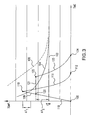
- the workpiece is initially at room temperature (condition/location 100) on the temperature against time plot of FIG. 3.
- FIG. 3 further shows a line 102 representing the equilibrium ⁇ transus (T e ⁇ ) as well as curves 104 and 106 of non-equilibrium ⁇ transus temperatures for the condensate and substrate, respectively (specific to the microstructural and thermal history of this Example 1).
- the equilibrium ⁇ transus temperature is a function of chemistry only. Because the exemplary condensate and substrate have the same chemistry, they share the same equilibrium ⁇ transus temperature (e.g., 960-1010°C for Ti-6Al-4V).
- the non-equilibrium ⁇ transus temperature is a function of composition, grain size/morphology, and heating rate. The smaller the grains, the lower the transus temperature. The more rapid the heating rate, the higher the transus temperature. At very slow heating rates, the equilibrium transus temperature equals the non-equilibrium transus temperature. Given very fine condensate grains, medium to coarse substrate grains, and a heating rate of approximately 100°C/sec, it is estimated that the difference between the non-equilibrium ⁇ transus of the two structures is about 100°C.
- the workpiece is heated 109 moderately above the condensate non-equilibrium ⁇ transus (condition/location 110).
- This heating may be under vacuum or in an inert atmosphere.
- This heating is advantageously rapid (e.g., occurring at a rate of 5-100°C/s or greater) so as to prevent excessive grain growth.
- Excessive grain growth e.g., above 150 ⁇ m ( ⁇ ASTM 2.5) or even 100 ⁇ m ( ⁇ ASTM 3.5), depending upon the application) is disadvantageous because it excessively reduces structural properties including one or more of ductility, fracture toughness, fatigue resistance, fretting fatigue resistance, corrosion resistance, wear resistance, crack nucleation resistance, and the like.
- the heating reaches a peak of ⁇ T 1 above the condensate non-equilibrium ⁇ transus of approximately 10-50°C.
- the heating substantially converts the condensate microstructure to ⁇ .
- the upper limit on ⁇ T 1 will reflect the microstructural/thermal history and is advantageously sufficiently low to avoid excessive ⁇ grain growth (in view of time considerations discussed below).
- the lower limit is advantageously high enough to provide essentially complete transition to the ⁇ phase ( ⁇ + ⁇ to ⁇ ).
- the substrate may be essentially unaffected.
- the workpiece is rapidly cooled 111 back to room temperature (condition/location 112).
- This heating may be under the same vacuum or atmosphere as the first stage.
- metastable martensite may accumulate in the condensate and the substrate.
- the cooling is advantageously sufficiently rapid to further limit ⁇ grain growth.
- the rapid heating and cooling maintain the condensate above its equilibrium ⁇ transus for a time interval sufficiently brief to avoid the excessive ⁇ grain growth noted above while providing the ⁇ phase transition.
- An exemplary time interval above the equilibrium ⁇ transus is 1.0 seconds or less.
- This microstructure is characterized by preservation of the boundaries of the prior ⁇ grains with ⁇ (e.g., in needle- or platelet-like form) in a ⁇ matrix within such boundaries.
- the rapid heating and cooling may provide a sufficiently short time at elevated temperature (in view of the magnitude of such temperature) to greatly limit oxidation even if the procedure is performed in an ambient atmosphere rather than under vacuum or an inert atmosphere.
- elevated temperature in view of the magnitude of such temperature
- An optional third stage involves annealing/aging by heating the workpiece to an annealing temperature (e.g., in the vicinity of 500-600°C for the exemplary Ti alloy).
- the exemplary annealing/aging is for a period of 1-24 hours and is effective to eliminate the martensite but without producing ⁇ grain growth. This may leave the condensate as essentially fine grain ⁇ (e.g., broadly smaller than 150 ⁇ m, more narrowly smaller than 100 ⁇ m, and preferably smaller than 50 ⁇ m ( ⁇ ASTM 2.5, 3.5, and 5.5, respectively)) plus the droplets and leaves the substrate as essentially medium to coarse grain ⁇ - ⁇ .
- the cooling of the second stage may be sufficiently slow to avoid martensite formation, in which case it is particularly appropriate to omit the aging/annealing.
- the initial heating stage 119 is similarly rapid but to a temperature above the equilibrium ⁇ transus but below the condensate non-equilibrium ⁇ transus.
- the resulting condition/location 120 may be at a temperature of ⁇ T 2 above the equilibrium ⁇ transus (e.g., by 10-30°C).
- the upper limit on this range is advantageously effective to avoid excessive ⁇ grain growth.
- the lower limit on this range is advantageously high enough to provide essentially complete transition to the ⁇ phase ( ⁇ + ⁇ to ⁇ ).
- the substrate may be essentially unaffected.
- the workpiece is maintained 121 at such a temperature for a moderate time interval (e.g., of about two seconds, more broadly 1.5-4.0 seconds or 1.0-5.0 seconds) to achieve a condition/location 122. It is during this time interval that the condensate microstructure changes to fine ⁇ as in condition/location 110. Thereafter, a rapid cooling 123 may transition the workpiece to a condition/location 124 similar to 112 and may, in turn, be followed by a similar annealing/aging if appropriate or desired.
- a moderate time interval e.g., of about two seconds, more broadly 1.5-4.0 seconds or 1.0-5.0 seconds
- the heating and cooling may be performed by a variety of techniques.
- One family of rapid heating techniques provides highly local heating (exemplary such techniques include induction heating, laser heating, electron beam heating, and the like). Such heating facilitates heating of the condensate with less substantial heating of the substrate, thereby minimizing any structural effects on the substrate.
- the desired heating depth may be controlled in view of the coating thickness by means including frequency control of induction heating, beam intensity of laser or electron beam heating, and the like. With some implementations of such heating, the heating may progress across the condensate (e.g., by moving or reorienting the workpiece relative to the heating source). Direct electrical resistance heating may be used to more generally heat the workpiece.
- the exemplary rapid cooling may be performed by forced cooling with an inert gas (especially when the heating is performed under vacuum), forced air cooling, liquid quench (e.g., in oil or water), and the like.
Abstract
Description
- The invention relates to deposition of Ti-based materials. More particularly, the invention relates to addressing deposition defects.
- A growing art exists regarding the deposition of Ti-based materials. For example, electron beam physical vapor deposition (EBPVD) may be used to build a coating or structural condensate of a Ti alloy atop a substrate of like or dissimilar nominal composition. Such techniques may be used in the aerospace industry for the repair or remanufacture of damaged or worn parts such as gas turbine engine components (e.g., blades, vanes, seals, and the like).
- Deposition defects, however, potentially compromise the condensate integrity. One group of such defects arises when a droplet of material is spattered onto the substrate or the accumulating condensate. The melt pool may contain additives not intended to vaporize and accumulate in the condensate. For example, U.S. Patent No. 5,474,809 discloses use of refractory elements in the melt pool. Once the droplet lands on the surface (of the substrate or the accumulating condensate) further deposition builds atop the droplet and the adjacent surface. Along the sides of the droplet, there may be microstructural discontinuities in the accumulating material due to the relative orientation of the sides of the droplet. As further material accumulates, these discontinuities may continue to build all the way to the final condensate surface.
- One aspect of the invention involves a method for treating a deposited titanium-base material from an initial condition to a treated condition. The material is heated from a first temperature to a second temperature. The first temperature is below an equilibrium β transus. The second temperature is above the equilibrium β transus. The heating includes a portion at a rate in excess of 5°C/s. The material is cooled from the second temperature to a third temperature below the equilibrium β transus.
- In various implementations, the heating may be to a peak at least 10°C above a non-equilibrium β transus. The material may be above the equilibrium β transus for a brief period (e.g., no more than 2.0 seconds). The heating and cooling may have sufficient rates to maintain a characteristic grain size of at least a matrix of the material below 100µm. In the initial condition, the material may include a number of defects having trunks with microstructures distinct from a microstructure of a matrix of the material. In the treated condition, the trunks' microstructures may be essentially integrated with the matrix microstructure.
- In one group of implementations, the heating may be to a peak 10-50°C above a non-equilibrium β transus. The material may be above the equilibrium β transus for a very brief period (e.g., no more than 1.0 seconds). In another group of potentially overlapping implementations, the heating may be to 1-30°C above the equilibrium β transus for a somewhat longer period (e.g., 1.0-5.0 seconds). The cooling may be sufficiently rapid to limit β growth to a characteristic size smaller than 100µm. One group of materials consist in largest weight parts of titanium, aluminum, and vanadium. An exemplary material thickness may be at least 2.0mm (e.g., for relatively thick structural and repair material, contrasted with thinner coatings).
- Other features, objects, and advantages of the invention will be apparent from the description and drawings, and from the claims.
- One or more preferred embodiments of the present invention will now be described by way of example only and with reference to the accompanying drawings in which:
- FIG. 1 is an optical micrograph of a Ti-6Al-4V condensate atop a like substrate and showing defects.
- FIG. 2 is a view of a healed condensate.
- FIG. 3 is a temperature-time diagram showing healing processes.
- Like reference numbers and designations in the various drawings indicate like elements.
- FIG. 1 shows a
condensate 20 accumulated atop a surface 22 of asubstrate 24. Exemplary condensate thickness may be from less than 0.2mm (e.g., for thin coatings) to in excess of 2mm (at least locally - e.g., for structural condensates such as certain repairs). The condensate has afirst defect 26 triggered by aspattered molybdenum droplet 28 that landed atop the surface 22. Exemplary droplet sizes are 30-500µm (measured as a characteristic (mean/median/mode) transverse dimension). The defect comprises atrunk 30 extending from thedroplet 28 toward the condensate surface (not shown). Asecond defect 32 is shown and may have been triggered by a droplet below the cut surface of the view. - The exemplary deposition is of nominal Ti-6Al-4V condensate atop a like substrate. Alternate depositions may include Ti-6Al-2Sn-4Zr-2Mo and Ti-8Al-1Mo-1V. The deposition may be from a melted ingot at least partially through a pool containing one or more refractory or other elements which may be essentially non-consumed during deposition (e.g., a pool formed from a 30%Mo-70%Zr mixture). Accordingly, the droplets may tend to have composition similar to the surface layers of the pool. In the absence of the non-consumed pool additive, the
droplet 28 might have a similar composition to the ingot yet still produce similar defects. Many droplets in systems using an Mo-containing pool would have Mo concentrations of at least 10% by weight; others at least 20%. This may be somewhat less than the Mo percentage of the non-expending pool material to reflect possible dilution by deposition material elements in the pool. - In the exemplary implementation, the
substrate 28 has an α-β microstructure of medium to coarse grains (e.g., 10-40µm characteristic grain size (e.g., mean) or about ASTM 10.5-6.5). An exemplary 10-20% by weight of the substrate is β phase with the remainder essentially α phase. The condensate matrix (away from the defects) also has an α-β microstructure but of very fine grains (e.g., acicular α grains of 5-10µm in length and 2-5µm in thickness, lengthwise oriented along the condensate growth/deposition direction). The trunk size will depend, in substantial part, upon the droplet size. Exemplary trunk diameters are from about 20µm to about 50µm. However, much larger trunks are possible. The trunks have a columnar α-β microstructure. This microstructure may have a characteristic grain size several times greater than that in the matrix and the grains may be elongated in the direction of accumulation (i.e., away from the substrate). Particularly in the case of very large diameter trunks (e.g., in excess of 100µm in diameter), there may be porosity around the trunk. The grain discontinuity at the trunk-matrix interface and the particular alignment of trunk grains may cause structural weaknesses affecting, inter alia, ductility, fracture toughness, fatigue resistance, fretting fatigue resistance, corrosion resistance, wear resistance, crack nucleation resistance, and the like. - We have, accordingly, developed heat treatment regimes for healing workpieces having such defects. FIG. 2 shows a
condensate 50 after healing. In this view, the substrate is not shown. Thecondensate surface 52 is, however, shown. A defect within the condensate had been caused by adroplet 54. The resultant trunk had propagated all the way to the surface forming abulge 56. The healed condensate, however, shows essentially no remaining artifacts of the defect other than theoriginal droplet 54 and bulge 56. The trunk has been microstructurally integrated with the condensate matrix as a fine β equiaxed microstructure (e.g., grain size of 10-100µm (~ASTM 10.5-3.5)). Additionally, laminar variations in chemistry or microstructure may be diminished or eliminated, thereby increasing the isotropy of the condensate mechanical properties. Thebulge 56 may be removed (e.g., during a subsequent surface machining). The healing permits the workpiece (e.g., a blade, vane, seal, or the like) to be operated at ambient temperature (e.g., 0-40°C) and/or at elevated temperatures (e.g., above 250°C, such as in the range of 300-500°C) essentially without increased chances of failure. - In a first exemplary healing method, the workpiece is initially at room temperature (condition/location 100) on the temperature against time plot of FIG. 3. FIG. 3 further shows a
line 102 representing the equilibrium β transus (Te β) as well ascurves - In a first stage, the workpiece is heated 109 moderately above the condensate non-equilibrium β transus (condition/location 110). This heating may be under vacuum or in an inert atmosphere. This heating is advantageously rapid (e.g., occurring at a rate of 5-100°C/s or greater) so as to prevent excessive grain growth. Excessive grain growth (e.g., above 150µm (~ASTM 2.5) or even 100µm (~ASTM 3.5), depending upon the application) is disadvantageous because it excessively reduces structural properties including one or more of ductility, fracture toughness, fatigue resistance, fretting fatigue resistance, corrosion resistance, wear resistance, crack nucleation resistance, and the like. The heating reaches a peak of ΔT1 above the condensate non-equilibrium β transus of approximately 10-50°C. The heating substantially converts the condensate microstructure to β. The upper limit on ΔT1 will reflect the microstructural/thermal history and is advantageously sufficiently low to avoid excessive β grain growth (in view of time considerations discussed below). The lower limit is advantageously high enough to provide essentially complete transition to the β phase (α+β to β). The substrate may be essentially unaffected.
- In a second stage, the workpiece is rapidly cooled 111 back to room temperature (condition/location 112). This heating may be under the same vacuum or atmosphere as the first stage. During this cooling, metastable martensite may accumulate in the condensate and the substrate. The cooling is advantageously sufficiently rapid to further limit β grain growth. The rapid heating and cooling maintain the condensate above its equilibrium β transus for a time interval sufficiently brief to avoid the excessive β grain growth noted above while providing the β phase transition. An exemplary time interval above the equilibrium β transus is 1.0 seconds or less. Once below the β transus, the β will transform to α+β in a β-transformed (also known as transformed β) microstructure. This microstructure is characterized by preservation of the boundaries of the prior β grains with α (e.g., in needle- or platelet-like form) in a β matrix within such boundaries. The rapid heating and cooling may provide a sufficiently short time at elevated temperature (in view of the magnitude of such temperature) to greatly limit oxidation even if the procedure is performed in an ambient atmosphere rather than under vacuum or an inert atmosphere. Thus, especially for workpieces to be exposed to relatively low thermal and mechanical stresses (e.g., some non-rotating turbine engine parts), there may be greater environmental flexibility during the heating and/or cooling.
- An optional third stage (not shown in FIG. 3) involves annealing/aging by heating the workpiece to an annealing temperature (e.g., in the vicinity of 500-600°C for the exemplary Ti alloy). The exemplary annealing/aging is for a period of 1-24 hours and is effective to eliminate the martensite but without producing β grain growth. This may leave the condensate as essentially fine grain β (e.g., broadly smaller than 150µm, more narrowly smaller than 100µm, and preferably smaller than 50µm (~ASTM 2.5, 3.5, and 5.5, respectively)) plus the droplets and leaves the substrate as essentially medium to coarse grain α-β. However, the cooling of the second stage may be sufficiently slow to avoid martensite formation, in which case it is particularly appropriate to omit the aging/annealing.
- In a second exemplary healing method, the
initial heating stage 119 is similarly rapid but to a temperature above the equilibrium β transus but below the condensate non-equilibrium β transus. The resulting condition/location 120 may be at a temperature of ΔT2 above the equilibrium β transus (e.g., by 10-30°C). The upper limit on this range is advantageously effective to avoid excessive β grain growth. The lower limit on this range is advantageously high enough to provide essentially complete transition to the β phase (α+β to β). The substrate may be essentially unaffected. - Rather than being immediately followed by rapid cooling, the workpiece is maintained 121 at such a temperature for a moderate time interval (e.g., of about two seconds, more broadly 1.5-4.0 seconds or 1.0-5.0 seconds) to achieve a condition/
location 122. It is during this time interval that the condensate microstructure changes to fine β as in condition/location 110. Thereafter, arapid cooling 123 may transition the workpiece to a condition/location 124 similar to 112 and may, in turn, be followed by a similar annealing/aging if appropriate or desired. - The heating and cooling may be performed by a variety of techniques. One family of rapid heating techniques provides highly local heating (exemplary such techniques include induction heating, laser heating, electron beam heating, and the like). Such heating facilitates heating of the condensate with less substantial heating of the substrate, thereby minimizing any structural effects on the substrate. The desired heating depth may be controlled in view of the coating thickness by means including frequency control of induction heating, beam intensity of laser or electron beam heating, and the like. With some implementations of such heating, the heating may progress across the condensate (e.g., by moving or reorienting the workpiece relative to the heating source). Direct electrical resistance heating may be used to more generally heat the workpiece. The exemplary rapid cooling may be performed by forced cooling with an inert gas (especially when the heating is performed under vacuum), forced air cooling, liquid quench (e.g., in oil or water), and the like.
- One or more embodiments of the present invention have been described. Nevertheless, it will be understood that various modifications may be made without departing from the scope of the invention. For example, details of the chemical composition of the particular substrate and condensate and of the physical configuration of the substrate and thickness of the condensate may influence details of any particular implementation. Accordingly, other embodiments are within the scope of the following claims.
Claims (29)
- A method for treating a deposited titanium-base material from an initial condition to a treated condition comprising:heating from a first temperature to a second temperature, the first temperature being below an equilibrium β transus, the second temperature being above the equilibrium β transus, and the heating including a portion at a rate in excess of 5°C/s; andcooling from the second temperature to a third temperature below the equilibrium β transus.
- The method of claim 1 wherein:the heating is to a peak at least 10°C above a non-equilibrium β transus; andthe material is above the equilibrium β transus for a period of no more than 2.0 seconds.
- The method of claim 1 or 2 wherein:the heating and cooling have sufficient rates to maintain a characteristic grain size of at least a matrix of the material smaller than 100µm.
- The method of claim 1, 2 or 3 wherein:in the initial condition, the material includes a plurality of defects having trunks with a microstructure distinct from a microstructure of a matrix of the material; andin the treated condition, the trunks' microstructure have been essentially integrated with the matrix microstructure.
- The method of any preceding claim wherein:the heating is to a peak 10-50°C above a non-equilibrium β transus; andthe material is above the equilibrium β transus for a period of no more than 1.0 seconds.
- The method of any preceding claim wherein:the heating is 1-30°C above the equilibrium β transus for a period of 1.0-5.0 seconds; andthe cooling is sufficiently rapid to limit β growth to a characteristic size smaller than 100µm.
- The method of any preceding claim wherein:the material consists in largest weight parts of titanium, aluminum, and vanadium; andthe material has a maximum thickness of at least 2.0mm.
- The method of any preceding claim wherein:the material is on a titanium-base substrate; andthe heating leaves essentially unaffected a microstructure of a major portion of the substrate.
- The method of any preceding claim wherein:the heating is selected from the group consisting of direct resistance heating, induction heating, electron beam heating, and combinations thereof.
- The method of any preceding claim further comprising:depositing the material on a titanium-base substrate.
- The method of claim 10 wherein:the depositing comprises electron beam physical vapor deposition.
- The method of claim 10 or 11 wherein:the material and the substrate consist essentially of an alloy of 5-7 weight percent aluminum, 3-5 weight percent vanadium, balance titanium, with less than 3 weight percent other components.
- The method of any preceding claim further comprising:maintaining the material at a temperature of 500-660°C.
- The method of any preceding claim further comprising:an annealing and aging step.
- The method of any preceding claim used to repair a gas turbine engine component having a titanium-base substrate.
- The method of claim 15 further comprising:operating the repaired component at a temperature in excess of 250°C.
- The method of any preceding claim wherein in the treated condition a laminar variation in at least a first alloy component is less than in the initial condition.
- A method for treating a deposited titanium-base material, the material initially having:a matrix having first nominal chemistry and a first characteristic grain size and first characteristic grain structure;a plurality of spits within the matrix and having:the method comprising:a droplet having a higher level of refractory impurities than the matrix; anda trunk extending from the droplet and having essentially the same chemistry as the matrix, but a larger second characteristic grain size and less equiaxed second grain structure,heating the material; andcooling the material, the heating and cooling being sufficiently rapid to convert an α-β microstructure of the material to an essentially β-transformed microstructure, optionally including metastable martensite, and having a characteristic grain size smaller than 100µm.
- The method of claim 18 wherein:the first nominal chemistry is essentially Ti-6Al-4V;the second nominal chemistry is essentially Ti-6Al-4V; andthe material is atop an essentially Ti-6Al-4V substrate.
- The method of claim 18 or 19 wherein:at least some of the spits are further characterized by porosity adjacent their trunks; andat least some of the porosity is healed.
- The method of claim 18, 19 or 20 wherein:the droplets comprise at least 10% of one or a combination of refractory metals, by weight.
- The method of any or claims 18 to 21 further comprising:an annealing/aging step effective to essentially eliminate the martensite.
- The method of any of claims 18 to 22 wherein:the material is a repair material on a turbine engine component.
- A component having:a Ti-based metallic substrate; anda Ti-based condensate atop the substrate and having:a surface;a plurality of embedded droplets below the surface;regions directly between the droplets and the surface characterized byan essentially β-transformed microstructure of a characteristic grain size below 100µm.
- The component of claim 24 wherein:at least some of said droplets are at least 200µm below the surface.
- The component of claim 24 or 25 wherein:at least some of said droplets are at least 20µm in characteristic transverse dimension.
- The component of claim 24, 25 or 26 wherein:at least some of said droplets comprise at least 20% Mo, by weight.
- The component of any of claims 24 to 27 wherein:the substrate and the condensate each consist essentially of Ti-6Al-4V.
- The component of any of claims 24 to 28 being one of a gas turbine engine compressor blade, fan blade, disk, drum rotor, bearing housing, vane, and seal element.
Applications Claiming Priority (1)
| Application Number | Priority Date | Filing Date | Title |
|---|---|---|---|
| US10/991,604 US20060105194A1 (en) | 2004-11-17 | 2004-11-17 | Defect healing of deposited titanium alloys |
Publications (2)
| Publication Number | Publication Date |
|---|---|
| EP1662019A1 true EP1662019A1 (en) | 2006-05-31 |
| EP1662019B1 EP1662019B1 (en) | 2008-07-16 |
Family
ID=35953858
Family Applications (1)
| Application Number | Title | Priority Date | Filing Date |
|---|---|---|---|
| EP05255509A Not-in-force EP1662019B1 (en) | 2004-11-17 | 2005-09-08 | Method of producing defect free deposited titanium alloys |
Country Status (8)
| Country | Link |
|---|---|
| US (1) | US20060105194A1 (en) |
| EP (1) | EP1662019B1 (en) |
| CN (1) | CN1776000A (en) |
| AT (1) | ATE401429T1 (en) |
| DE (1) | DE602005008169D1 (en) |
| MX (1) | MXPA05012417A (en) |
| SG (1) | SG122960A1 (en) |
| UA (1) | UA79864C2 (en) |
Families Citing this family (2)
| Publication number | Priority date | Publication date | Assignee | Title |
|---|---|---|---|---|
| JP5522106B2 (en) * | 2011-03-31 | 2014-06-18 | アイシン・エィ・ダブリュ株式会社 | Steel gear and manufacturing method thereof |
| JP5522105B2 (en) * | 2011-03-31 | 2014-06-18 | アイシン・エィ・ダブリュ株式会社 | Steel gear and manufacturing method thereof |
Citations (1)
| Publication number | Priority date | Publication date | Assignee | Title |
|---|---|---|---|---|
| US5474809A (en) * | 1994-12-27 | 1995-12-12 | General Electric Company | Evaporation method |
Family Cites Families (3)
| Publication number | Priority date | Publication date | Assignee | Title |
|---|---|---|---|---|
| US5879760A (en) * | 1992-11-05 | 1999-03-09 | The United States Of America As Represented By The Secretary Of The Air Force | Titanium aluminide articles having improved high temperature resistance |
| US6626228B1 (en) * | 1998-08-24 | 2003-09-30 | General Electric Company | Turbine component repair system and method of using thereof |
| US6190473B1 (en) * | 1999-08-12 | 2001-02-20 | The Boenig Company | Titanium alloy having enhanced notch toughness and method of producing same |
-
2004
- 2004-11-17 US US10/991,604 patent/US20060105194A1/en not_active Abandoned
-
2005
- 2005-09-08 EP EP05255509A patent/EP1662019B1/en not_active Not-in-force
- 2005-09-08 AT AT05255509T patent/ATE401429T1/en not_active IP Right Cessation
- 2005-09-08 DE DE602005008169T patent/DE602005008169D1/en active Active
- 2005-09-23 UA UAA200509015A patent/UA79864C2/en unknown
- 2005-11-14 SG SG200508453A patent/SG122960A1/en unknown
- 2005-11-17 CN CN200510125479.2A patent/CN1776000A/en active Pending
- 2005-11-17 MX MXPA05012417A patent/MXPA05012417A/en not_active Application Discontinuation
Patent Citations (1)
| Publication number | Priority date | Publication date | Assignee | Title |
|---|---|---|---|---|
| US5474809A (en) * | 1994-12-27 | 1995-12-12 | General Electric Company | Evaporation method |
Non-Patent Citations (1)
| Title |
|---|
| IVASISHIN O M ET AL: "ENHANCING THE MECHANICAL PROPERTIES OF TITANIUM ALLOYS WITH RAPID HEAT TREATMENT", JOM, MINERALS METALS & MATERIALS SOCIETY, WARRENDALE, PA, US, vol. 48, no. 7, 1 July 1996 (1996-07-01), pages 48 - 52, XP000597347, ISSN: 1047-4838 * |
Also Published As
| Publication number | Publication date |
|---|---|
| UA79864C2 (en) | 2007-07-25 |
| MXPA05012417A (en) | 2006-05-19 |
| SG122960A1 (en) | 2006-06-29 |
| CN1776000A (en) | 2006-05-24 |
| EP1662019B1 (en) | 2008-07-16 |
| ATE401429T1 (en) | 2008-08-15 |
| DE602005008169D1 (en) | 2008-08-28 |
| US20060105194A1 (en) | 2006-05-18 |
Similar Documents
| Publication | Publication Date | Title |
|---|---|---|
| US5498484A (en) | Thermal barrier coating system with hardenable bond coat | |
| US6659332B2 (en) | Directionally solidified article with weld repair | |
| Majumdar et al. | Laser surface engineering of titanium and its alloys for improved wear, corrosion and high-temperature oxidation resistance | |
| JP5188702B2 (en) | Construction methods associated with bond coats having low deposited aluminum levels | |
| US9382605B2 (en) | Economic oxidation and fatigue resistant metallic coating | |
| US6689487B2 (en) | Thermal barrier coating | |
| JP2005298973A (en) | Nickel based superalloy, composition, article and gas turbine engine blade | |
| EP1905953A2 (en) | Low plasticity burnishing of coated titanium parts | |
| US20190299288A1 (en) | METHOD FOR PRODUCING A COMPONENT FROM A GRADED TiAl ALLOY AND COMPONENT PRODUCED THEREFROM | |
| US6277500B1 (en) | Gas turbine component | |
| US20060257688A1 (en) | MCrAlx alloy, protective layer made from MCrAlx alloy, and production processes | |
| GB2440334A (en) | A method of controlling the microstructure of a metal | |
| US8221841B2 (en) | Pre-coating burnishing of erosion coated parts | |
| JP2008063657A (en) | Method for applying resistant coating to fretting wear at high temperature | |
| EP1273674A1 (en) | Heat treatment of titanium-alloy article having martensitic structure | |
| GB2536981A (en) | Method for joining high temperature materials and articles made therewith | |
| US6284691B1 (en) | Yttria-stabilized zirconia feed material | |
| US20200080183A1 (en) | Treatment processes for superalloy articles and related articles | |
| US8252376B2 (en) | Method for restoring the microstructure of a textured article and for refurbishing a gas turbine blade or vane | |
| EP1662019B1 (en) | Method of producing defect free deposited titanium alloys | |
| JP2001288554A (en) | Repairing material, method for repairing heat resisting alloy member, and hot zone parts repaired by the method | |
| EP2236642A1 (en) | Controlled oxidation of bond coat | |
| EP3708694A1 (en) | Laser induced, fine grained, gamma phase surface for nicocraiy coatings prior to ceramic coat | |
| US6719853B2 (en) | Method for restoring the microstructure of a textured article and for refurbishing a gas turbine blade or vane | |
| US20030118873A1 (en) | Stabilized zirconia thermal barrier coating with hafnia |
Legal Events
| Date | Code | Title | Description |
|---|---|---|---|
| PUAI | Public reference made under article 153(3) epc to a published international application that has entered the european phase |
Free format text: ORIGINAL CODE: 0009012 |
|
| AK | Designated contracting states |
Kind code of ref document: A1 Designated state(s): AT BE BG CH CY CZ DE DK EE ES FI FR GB GR HU IE IS IT LI LT LU LV MC NL PL PT RO SE SI SK TR |
|
| AX | Request for extension of the european patent |
Extension state: AL BA HR MK YU |
|
| 17P | Request for examination filed |
Effective date: 20061128 |
|
| 17Q | First examination report despatched |
Effective date: 20070103 |
|
| AKX | Designation fees paid |
Designated state(s): AT BE BG CH CY CZ DE DK EE ES FI FR GB GR HU IE IS IT LI LT LU LV MC NL PL PT RO SE SI SK TR |
|
| GRAP | Despatch of communication of intention to grant a patent |
Free format text: ORIGINAL CODE: EPIDOSNIGR1 |
|
| GRAS | Grant fee paid |
Free format text: ORIGINAL CODE: EPIDOSNIGR3 |
|
| GRAA | (expected) grant |
Free format text: ORIGINAL CODE: 0009210 |
|
| AK | Designated contracting states |
Kind code of ref document: B1 Designated state(s): AT BE BG CH CY CZ DE DK EE ES FI FR GB GR HU IE IS IT LI LT LU LV MC NL PL PT RO SE SI SK TR |
|
| REG | Reference to a national code |
Ref country code: GB Ref legal event code: FG4D |
|
| REG | Reference to a national code |
Ref country code: CH Ref legal event code: EP |
|
| REF | Corresponds to: |
Ref document number: 602005008169 Country of ref document: DE Date of ref document: 20080828 Kind code of ref document: P |
|
| REG | Reference to a national code |
Ref country code: IE Ref legal event code: FG4D |
|
| NLV1 | Nl: lapsed or annulled due to failure to fulfill the requirements of art. 29p and 29m of the patents act | ||
| PG25 | Lapsed in a contracting state [announced via postgrant information from national office to epo] |
Ref country code: IS Free format text: LAPSE BECAUSE OF FAILURE TO SUBMIT A TRANSLATION OF THE DESCRIPTION OR TO PAY THE FEE WITHIN THE PRESCRIBED TIME-LIMIT Effective date: 20081116 Ref country code: LT Free format text: LAPSE BECAUSE OF FAILURE TO SUBMIT A TRANSLATION OF THE DESCRIPTION OR TO PAY THE FEE WITHIN THE PRESCRIBED TIME-LIMIT Effective date: 20080716 Ref country code: NL Free format text: LAPSE BECAUSE OF FAILURE TO SUBMIT A TRANSLATION OF THE DESCRIPTION OR TO PAY THE FEE WITHIN THE PRESCRIBED TIME-LIMIT Effective date: 20080716 |
|
| PG25 | Lapsed in a contracting state [announced via postgrant information from national office to epo] |
Ref country code: PT Free format text: LAPSE BECAUSE OF FAILURE TO SUBMIT A TRANSLATION OF THE DESCRIPTION OR TO PAY THE FEE WITHIN THE PRESCRIBED TIME-LIMIT Effective date: 20081216 Ref country code: BG Free format text: LAPSE BECAUSE OF FAILURE TO SUBMIT A TRANSLATION OF THE DESCRIPTION OR TO PAY THE FEE WITHIN THE PRESCRIBED TIME-LIMIT Effective date: 20081016 Ref country code: SI Free format text: LAPSE BECAUSE OF FAILURE TO SUBMIT A TRANSLATION OF THE DESCRIPTION OR TO PAY THE FEE WITHIN THE PRESCRIBED TIME-LIMIT Effective date: 20080716 Ref country code: ES Free format text: LAPSE BECAUSE OF FAILURE TO SUBMIT A TRANSLATION OF THE DESCRIPTION OR TO PAY THE FEE WITHIN THE PRESCRIBED TIME-LIMIT Effective date: 20081027 Ref country code: AT Free format text: LAPSE BECAUSE OF FAILURE TO SUBMIT A TRANSLATION OF THE DESCRIPTION OR TO PAY THE FEE WITHIN THE PRESCRIBED TIME-LIMIT Effective date: 20080716 Ref country code: FI Free format text: LAPSE BECAUSE OF FAILURE TO SUBMIT A TRANSLATION OF THE DESCRIPTION OR TO PAY THE FEE WITHIN THE PRESCRIBED TIME-LIMIT Effective date: 20080716 Ref country code: LV Free format text: LAPSE BECAUSE OF FAILURE TO SUBMIT A TRANSLATION OF THE DESCRIPTION OR TO PAY THE FEE WITHIN THE PRESCRIBED TIME-LIMIT Effective date: 20080716 |
|
| PG25 | Lapsed in a contracting state [announced via postgrant information from national office to epo] |
Ref country code: BE Free format text: LAPSE BECAUSE OF FAILURE TO SUBMIT A TRANSLATION OF THE DESCRIPTION OR TO PAY THE FEE WITHIN THE PRESCRIBED TIME-LIMIT Effective date: 20080716 |
|
| PG25 | Lapsed in a contracting state [announced via postgrant information from national office to epo] |
Ref country code: MC Free format text: LAPSE BECAUSE OF NON-PAYMENT OF DUE FEES Effective date: 20080930 Ref country code: EE Free format text: LAPSE BECAUSE OF FAILURE TO SUBMIT A TRANSLATION OF THE DESCRIPTION OR TO PAY THE FEE WITHIN THE PRESCRIBED TIME-LIMIT Effective date: 20080716 Ref country code: DK Free format text: LAPSE BECAUSE OF FAILURE TO SUBMIT A TRANSLATION OF THE DESCRIPTION OR TO PAY THE FEE WITHIN THE PRESCRIBED TIME-LIMIT Effective date: 20080716 |
|
| PLBE | No opposition filed within time limit |
Free format text: ORIGINAL CODE: 0009261 |
|
| STAA | Information on the status of an ep patent application or granted ep patent |
Free format text: STATUS: NO OPPOSITION FILED WITHIN TIME LIMIT |
|
| PG25 | Lapsed in a contracting state [announced via postgrant information from national office to epo] |
Ref country code: SK Free format text: LAPSE BECAUSE OF FAILURE TO SUBMIT A TRANSLATION OF THE DESCRIPTION OR TO PAY THE FEE WITHIN THE PRESCRIBED TIME-LIMIT Effective date: 20080716 Ref country code: RO Free format text: LAPSE BECAUSE OF FAILURE TO SUBMIT A TRANSLATION OF THE DESCRIPTION OR TO PAY THE FEE WITHIN THE PRESCRIBED TIME-LIMIT Effective date: 20080716 Ref country code: CZ Free format text: LAPSE BECAUSE OF FAILURE TO SUBMIT A TRANSLATION OF THE DESCRIPTION OR TO PAY THE FEE WITHIN THE PRESCRIBED TIME-LIMIT Effective date: 20080716 |
|
| 26N | No opposition filed |
Effective date: 20090417 |
|
| REG | Reference to a national code |
Ref country code: FR Ref legal event code: ST Effective date: 20090529 |
|
| PG25 | Lapsed in a contracting state [announced via postgrant information from national office to epo] |
Ref country code: IE Free format text: LAPSE BECAUSE OF NON-PAYMENT OF DUE FEES Effective date: 20080908 |
|
| PG25 | Lapsed in a contracting state [announced via postgrant information from national office to epo] |
Ref country code: IT Free format text: LAPSE BECAUSE OF FAILURE TO SUBMIT A TRANSLATION OF THE DESCRIPTION OR TO PAY THE FEE WITHIN THE PRESCRIBED TIME-LIMIT Effective date: 20080716 |
|
| PG25 | Lapsed in a contracting state [announced via postgrant information from national office to epo] |
Ref country code: FR Free format text: LAPSE BECAUSE OF NON-PAYMENT OF DUE FEES Effective date: 20080930 |
|
| PG25 | Lapsed in a contracting state [announced via postgrant information from national office to epo] |
Ref country code: SE Free format text: LAPSE BECAUSE OF FAILURE TO SUBMIT A TRANSLATION OF THE DESCRIPTION OR TO PAY THE FEE WITHIN THE PRESCRIBED TIME-LIMIT Effective date: 20081016 |
|
| REG | Reference to a national code |
Ref country code: CH Ref legal event code: PL |
|
| PG25 | Lapsed in a contracting state [announced via postgrant information from national office to epo] |
Ref country code: PL Free format text: LAPSE BECAUSE OF FAILURE TO SUBMIT A TRANSLATION OF THE DESCRIPTION OR TO PAY THE FEE WITHIN THE PRESCRIBED TIME-LIMIT Effective date: 20080716 |
|
| PG25 | Lapsed in a contracting state [announced via postgrant information from national office to epo] |
Ref country code: LU Free format text: LAPSE BECAUSE OF NON-PAYMENT OF DUE FEES Effective date: 20080908 Ref country code: HU Free format text: LAPSE BECAUSE OF FAILURE TO SUBMIT A TRANSLATION OF THE DESCRIPTION OR TO PAY THE FEE WITHIN THE PRESCRIBED TIME-LIMIT Effective date: 20090117 Ref country code: CY Free format text: LAPSE BECAUSE OF FAILURE TO SUBMIT A TRANSLATION OF THE DESCRIPTION OR TO PAY THE FEE WITHIN THE PRESCRIBED TIME-LIMIT Effective date: 20080716 |
|
| PG25 | Lapsed in a contracting state [announced via postgrant information from national office to epo] |
Ref country code: TR Free format text: LAPSE BECAUSE OF FAILURE TO SUBMIT A TRANSLATION OF THE DESCRIPTION OR TO PAY THE FEE WITHIN THE PRESCRIBED TIME-LIMIT Effective date: 20080716 |
|
| PG25 | Lapsed in a contracting state [announced via postgrant information from national office to epo] |
Ref country code: GR Free format text: LAPSE BECAUSE OF FAILURE TO SUBMIT A TRANSLATION OF THE DESCRIPTION OR TO PAY THE FEE WITHIN THE PRESCRIBED TIME-LIMIT Effective date: 20081017 Ref country code: CH Free format text: LAPSE BECAUSE OF NON-PAYMENT OF DUE FEES Effective date: 20090930 Ref country code: LI Free format text: LAPSE BECAUSE OF NON-PAYMENT OF DUE FEES Effective date: 20090930 |
|
| PGFP | Annual fee paid to national office [announced via postgrant information from national office to epo] |
Ref country code: GB Payment date: 20160825 Year of fee payment: 12 Ref country code: DE Payment date: 20160823 Year of fee payment: 12 |
|
| REG | Reference to a national code |
Ref country code: DE Ref legal event code: R082 Ref document number: 602005008169 Country of ref document: DE Representative=s name: SCHMITT-NILSON SCHRAUD WAIBEL WOHLFROM PATENTA, DE |
|
| REG | Reference to a national code |
Ref country code: DE Ref legal event code: R082 Ref document number: 602005008169 Country of ref document: DE Representative=s name: SCHMITT-NILSON SCHRAUD WAIBEL WOHLFROM PATENTA, DE Ref country code: DE Ref legal event code: R081 Ref document number: 602005008169 Country of ref document: DE Owner name: UNITED TECHNOLOGIES CORP. (N.D.GES.D. STAATES , US Free format text: FORMER OWNER: UNITED TECHNOLOGIES CORPORATION, HARTFORD, CONN., US |
|
| REG | Reference to a national code |
Ref country code: DE Ref legal event code: R119 Ref document number: 602005008169 Country of ref document: DE |
|
| GBPC | Gb: european patent ceased through non-payment of renewal fee |
Effective date: 20170908 |
|
| PG25 | Lapsed in a contracting state [announced via postgrant information from national office to epo] |
Ref country code: DE Free format text: LAPSE BECAUSE OF NON-PAYMENT OF DUE FEES Effective date: 20180404 Ref country code: GB Free format text: LAPSE BECAUSE OF NON-PAYMENT OF DUE FEES Effective date: 20170908 |