BACKGROUND OF THE INVENTION
1. Field of the Invention
-
The present invention relates to a method for operating a crane for handling cargo containers, a controlling device for a crane, and a crane provided with the control device.
-
This application is based on Japanese Patent Application No. 2001-352233, the content of which is incorporated herein by reference.
2. Description of Related Art
-
Conventionally, it is necessary to take various steps in order to move a cargo container (hereinafter may be simply referred to as "cargo") using a crane from an initial position where the cargo is hoisted to a target position where the cargo is unloaded. This is because the operation of a crane is affected by composite movements thereof, such as hoisting and turning of a jib (also called a boom), and is restricted to be within the movable range of the crane based on its mechanical structure.
-
A conventional method for operating a crane will be explained with reference to FIGS. 5A and 5B and 6A and 6B.
-
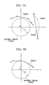
FIG. 5A is a diagram showing tracks.of a jib point (an end portion of the jib) when a cargo is moved in a straight line at one time or a plurality of times. Also, FIG 5B is a diagram showing a track of a jib point when a cargo is moved using a tangent of a circle having a minimum turning radius (hereinafter also referred to as a minimum turning circle).
-
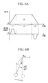
FIG. 6A is a diagram showing graphs which indicate the relationship between the moving rate of the jib end portion and time, and between a swinging angle of a hoisted cargo relative to the vertical direction and time. FIG. 6B is a schematic diagram showing a model of a moving pendulum.
-
In FIGS. 5A and 5B, the symbol O indicates the center of turning a crane, i.e., the center of the jib operating radius in a cargo handling operation using the crane. Also, the symbols A, and A indicate initial positions of a cargo, and the symbols B, and B1 indicate target positions of a cargo. The circles having a radius r0 shown in the figure indicate a minimum turning circle of a crane, and this means that a handling operation for a cargo cannot be performed within the circle due to the mechanical restriction of the crane.
-
The track 3 of the jib point shown in FIG. 5A is described in Japanese Laid-Open Patent Application No. 2000-38286. According to this document, a crane moves a cargo while making a polygonal linear motion, which means a combination of linear motions, by means of turning and jib hoisting operations. More specifically, the jib point of a crane hoists a cargo at the initial position A, and turns to the right hand side direction around the rotation center O in the figure. The shortest track between the initial position A and the target position B is, of course, a straight line connecting the position A with the position B. However, since the track of a cargo cannot pass through the minimum turning circle due to the restriction in the mechanical structure of the crane, the crane moves the cargo so as to avoid the minimum turning circle while increasing the operation radius in the direction separating away from the rotation center O. In this case, the transfer track of the jib point is linear, and the cargo is moved by a combination of the jib hoisting and turning operations.
-
After the cargo is linearly moved for a certain distance, the moving direction of the jib point is changed so as to move along the minimum turning circle. In this case, the transfer track of the jib point is also made linear, and the cargo is moved by a combination of jib bending and turning operations.
-
The moving direction of the jib point is further changed half way so that the cargo may be linearly moved towards the target position B. According to these operations, the track 3 forms a part of a polygonal shape, which is formed by a combination of a plurality of linear lines, and the cargo is eventually delivered to the target position B.
-
On the other hand, there are cases where the transfer track of a cargo is a linear line connecting the initial position A 1 and the target position B 1. In many of these cases, the initial position A1 and the target position B1 are located relatively far from the minimum turning circle, or the moving distance of a cargo is relatively short.
-
In general, when a cargo is moved from the initial positionAl to the target position B1, as indicated by a dotted track 1 in FIG 5A, the hoisting operation of the jib is not used many times, and the operation of the crane is mainly carried out by turning operations of the jib. In such a case, since the track of a cargo is shifted in the radius direction as the cargo approaches to the target position B 1, the jib hoisting operation is performed at the end of the track 1 in order to correct the shift in the radius direction.
-
In this case, it is expected that the cargo will swing in the moving direction as well as in the radius direction. The reason for this is that inertia due to acceleration and deceleration is applied to the cargo in the moving direction thereof, and a centrifugal force due to the rotation of the jib is applied to the cargo in the radius direction.
-
Accordingly, as shown in a track 2, by connecting the initial position A1 and the target position B 1 with one straight line, the shortest path for moving the cargo is realized, and the centrifugal force, which would affect the movement of the cargo, can be eliminated.
-
However, it is also necessary to stop swinging of a cargo for the above-mentioned linear transfer track. Methods for stopping swinging of a cargo being linearly moved is disclosed in Japanese Laid-Open Patent Application No. 2000-313586 and Japanese Laid-Open Patent Application No. 2000-153989. These documents relate to methods for controlling the speed of a trolley of a portal crane which hoists a cargo. According to the methods disclosed in the documents, the length of a rope for hoisting a cargo is measured to obtain a motion pattern of a virtual pendulum, and the speed of the trolley is controlled so that the swinging period of the cargo matches the motion pattern of the virtual pendulum.
-
Next, a method for stopping swinging of a cargo being linearly moved will be explained with reference to the attached drawings.
-
In the following, a trolley is used to move a cargo in a certain direction, and can be understood by swinging of a simple pendulum.
-
As shown in FIG. 6A, the trolley accelerates during an acceleration time period t1, and then moves at a constant speed, which is the speed at the end of the acceleration, during a constant speed time period t2. Then, after the end of the constant speed time period t2, the trolley decelerates during a deceleration time period t3. Finally, the speed of the trolley reaches zero at the target position B1, and the trolley stops. Note that the area of the trapezoid S in FIG. 6A indicates a distance between the initial position A 1 and the target position B 1.
-
Also, the swinging angle θ of a cargo will be explained with reference to FIG. 6B. During the acceleration time period t1, the swinging angle of the cargo reaches a maximum while swinging in the direction opposite the moving direction, and then the swinging angle gradually decreases. At the same time that the trolley enters the constant speed time period t2, the swinging angle of the cargo becomes zero. Then, during the deceleration time period t3, the swinging angle of the cargo reaches a maximum while swinging in the direction same as the moving direction, and then the swinging angle gradually decreases. At the same time the trolley stops, the swinging angle of the cargo becomes zero.
-
That is, in order to stop the swing of a cargo, each of the acceleration time t1 and the deceleration time t2 is adjusted to be a multiple (an integer) of the period of a virtual pendulum shown in FIG. 6B. In this way, it becomes possible to stop the swing of a cargo since the swing period of the cargo matches the above-mentioned virtual pendulum.
-
Also, it is possible to stop swinging of a cargo by adjusting each of a total time of the acceleration time period t1 and the constant speed time period t2 and a total time of the constant speed time period t2 and the deceleration time period t3 so as to match a multiple (an integer) of the period of a virtual pendulum for the cargo. This method is suitable when a cargo is moved a relatively short distance.
-
These methods for stopping the swing of a hoisted cargo mean a patterned swing stop in which the swing of a cargo is stopped based on the motion of a virtual pendulum, taking into account the actual length of a rope. In the above documents, it is also possible to improve the accuracy in stopping the swing of a cargo by providing a sensor, such as an accelerometer, and applying an actual feedback control based on figures obtained from the sensor.
-
Next, a track 4 of the jib point will be explained with reference to FIG. 5B.
-
The track 4 of the jib point shown in FIG. 5B is disclosed in Japanese Laid-Open Patent Application No. 8-245164. According to this document, the jib point of the crane linearly moves from the initial position A so as to approach to the minimum turning circle. Then, when the jib point reaches the minimum turning circle, it follows on a part of the circle. After this, the jib point separates away from the minimum turning circle half way, and linearly moves towards the target position B.
-
That is, the track 4 is formed by tangents of the minimum turning circle with respect to the initial position A and the target position B, and a part of the minimum turning circle. Accordingly, the track 4 is the shortest path connecting the initial position A and the target position B for the case where the cargo cannot pass through the minimum turning circle.
-
However, the above-mentioned conventional operation methods for a crane have the following problems.
-
First, stopping of the swing of a hoisted cargo cannot follow the change in the length of a rope. That is, in the above conventional methods, although a swing stop control is carried out by detecting the length of the rope, the methods are only applied for the case where the length of the rope is always constant from the initial position of hoisting the cargo. When a portal crane including a trolley is used, in which the length of a rope is constant, the rope is brought up and down in a non-swinging state when a cargo has reached a target position. Accordingly, no significant problems tend to be caused regarding the control for stopping swing of a cargo.
-
For the case where the trolley moves at the same time the rope is brought up and down, it is necessary to take into account the change in the length of the rope. However, in arithmetic expressions for acceleration of a trolley which are disclosed in Japanese Laid-Open Patent Application No. 2000-313586 or Japanese Laid-Open Patent Application No. 2000-153989, acceleration at an actual rope length is not take into consideration, and hence, the swing pattern of a hoisted cargo and that of a virtual pendulum are shifted if there is a change in the actual length of the rope.
-
However, in a jib crane provided with a rotatable jib, such as a mobile harbor crane, a crawler crane, a wheel crane, and a tower crane, the length of a rope varies in accordance with the degree of jib hoisting. In such jib cranes, it is possible to estimate the length of a rope based on the jib hoisting operation. However, in an actual cargo handling operation using a crane, it is necessary to avoid obstacles while moving a cargo, or to carry out a subtle positioning operation, and it is rare that the actual rope length, which is controlled by the operator of a crane, matches the estimated rope length.
-
Accordingly, the rope length, which is computed for stopping the swing of a cargo, changes from time to time, and the period of the hoisted cargo computed based on the virtual pendulum shifts from the period of the already computed virtual pendulum. Accordingly, it is often difficult to stop the swing of the hoisted cargo.
-
Also, as a second point of the problems, for the case where a straight line connecting an initial position and a target position crosses over the minimum turning circle, a large centrifugal force is often applied to a cargo in the above-mentioned track 3 using a polygonal linear motion, and to the track 4 using tangents of the minimum turning circle.
-
The reason for this is because the moving direction of a hoisted cargo is rapidly changed in the track 3 using the polygonal linear motion shown in FIG. 5A at the bending portions thereof, and inertia is generated due to the motion of the hoisted cargo. Also, as for the case of the track 4 using the tangents of the minimum turning circle shown in FIG. 5B, the radius of the path of the hoisted cargo decreases when it passes along the part of the minimum turning circle, and hence, a large centrifugal force is applied to the cargo.
-
Moreover, since both the tracks 3 and 4 shown in FIGS. 5A and 5B, respectively, are discontinuous moving paths, swing of a cargo may be generated in the direction different from the moving direction, or the cargo may be temporarily stopped when the direction of the cargo is changed in the middle of the track.
-
Due to this second problem, it is necessary to slow the moving rate of the hoisted cargo using a crane, and this problem should be solved in order to improve working efficiency of operations using a crane.
-
Also, in the first problem described above in which the cargo is linearly moved, if the swing of the cargo is not stopped, time for stopping the cargo must be included in the operation time. Accordingly, the working efficiency of the crane is reduced.
SUMMARY OF THE INVENTION
-
The present invention takes into consideration the above-mentioned circumstances, and has as an object to provide a method for operating a crane, a controlling device for a crane, and a crane provided with the control device, by which the degree of swinging of a cargo in a handling operation using the crane is suppressed to a minimum level, and the working efficiency of the crane can be improved.
-
In order to achieve the above object, the first aspect of the present invention provides a method for operating a crane provided with a jib having a jib point from which a cargo is hung via a rope member, the cargo being moved from an initial position to a target position to carry out a cargo handling operation, including: a hypothetical rope length setting step in which a hypothetical length of the rope member is set; a hypothetical acceleration pattern operation step in which a hypothetical acceleration pattern for swing angle of the rope member is operated for a case where the cargo is to be stopped at the target position provided that the hypothetical length of the rope member does not change and that the cargo is linearly moved from the initial position to the target position; a rope length change obtaining step in which a change in an actual length of the rope member is obtained; a jib point acceleration pattern operation step in which an acceleration pattern for the jib point is operated taking into account the change in the actual length of the rope member obtained in the rope length change obtaining step so that an acceleration pattern for swing angle of the rope member matches the hypothetical acceleration pattern obtained in the hypothetical acceleration pattern operation step; and a jib moving step in which the jib point is linearly moved based on results obtained in the jib point acceleration pattern operation step.
-
According to the above method for operating a crane, a hypothetical acceleration pattern is obtained from the hypothetical acceleration pattern operation step so that the cargo is transferred from the initial position to the target position during a period in which a hypothetical pendulum having a hypothetical rope length returns to a zero point from the zero point. Then, the jib point acceleration pattern for the jib point is operated so that an acceleration pattern for a swing angle at the actual rope length obtained in the rope length change obtaining step matches the above-mentioned hypothetical acceleration pattern.
-
In this manner, the jib point acceleration pattern by which the swing of the cargo is stopped at the target position is always operated, and a command value to the jib moving step is output based on the result of the operation so as to stop the actual swing of the cargo due to the operation of the jib and crane.
-
Note that this method is particularly useful when it is possible to linearly move the jib point.
-
Also, according to the above method, the swing of the cargo in the moving direction when the cargo is linearly transferred is stopped regardless of the change in the length of the rope member. Accordingly, an operator of the crane can perform manual operation, and hence the degree of flexibility in the operation is increased. Also, according to the above method, it becomes possible to transfer the cargo to the target position accurately and safely. Moreover, since the swing of the cargo is stopped, it becomes unnecessary for an operator to carry out a swing stop operation, and hence, labor for the operator is reduced. Furthermore, the efficiency in a cargo handling process may be improved since the cycle time required for repeatedly moving a cargo is shortened.
-
In accordance with the second aspect of the present invention, the hypothetical rope length is set based on a maximum acceleration for linearly moving the jib point, the maximum acceleration being determined based on performance of the crane.
-
The hypothetical rope length is a value that is operated in the hypothetical acceleration pattern operation step. The value can be arbitrary set, and determines the hypothetical acceleration pattern. Accordingly, a hypothetical acceleration in the hypothetical acceleration pattern is also obtained based on the hypothetical rope length, and can be arbitrary set.
-
It is preferable that the hypothetical acceleration pattern be obtained so as to have as large an acceleration as possible in order to improve the workability of the crane.
-
When the jib is actually moved, however, there is a limitation in the acceleration. That is, the limitation due to the mechanical structure of the crane.
-
Accordingly, a most effective hypothetical acceleration pattern can be obtained by determining the hypothetical rope length based on the maximum acceleration of the jib movement, and in practice, the jib point is moved in the vicinity of the maximum acceleration for the crane.
-
Also, since the hypothetical rope length is set based on the maximum acceleration for linearly moving the jib, which is determined based on the performance of the crane, it becomes possible to rapidly transfer a cargo using a maximum performance of the crane while avoiding a high load operation exceeding the performance of the crane. Accordingly, the efficiency in the cargo handling operation can be improved.
-
In accordance with the third aspect of the present invention, a jib point acceleration a
k in the jib point acceleration pattern operation step is expressed by the following formula:
where λ
0 is the hypothetical rope length, λ is the length of the rope member, v is a velocity of the rope member, κ is an acceleration of the rope member, a
k0 is a jib point hypothetical acceleration in the hypothetical acceleration pattern operation step, θ is a swing angle of the cargo, ω is a swing angular velocity of the cargo, and g is gravitational acceleration.
-
In this aspect, the jib point acceleration ak is obtained using the above formula (1). By using the formula (1), it becomes possible to correspond to the change in the rope length which may vary at every moment. That is, the jib point acceleration ak is changed at every moment so as to correspond to the change in the actual rope length while recognizing the swing angle θ of the cargo. In this manner, the period of the cargo is matched a swing-stop period obtained using the hypothetical acceleration pattern.
-
Here, an operation process for obtaining the above formula (1) will be explained.
-
An equation of the motion for a simple pendulum may be expressed as the following formula (2):
where a
k is an acceleration of the pendulum, χ is a swing amount of the pendulum, λ, is the rope length, and g is the gravitational acceleration.
-
Note that since each symbol contained in the above equation (for instance, the acceleration of the pendulum, ak, the rope length, λ, and the swing angle of the pendulum, θ) is obtained in the same state as the symbols explained above (for instance, the jib point acceleration, ak, the length of the rope member for carrying the cargo, λ, and the swing angle of the hoisted cargo, θ), they are indicated using the same symbols.
-
In the above formula (2), when the swing angle of the pendulum θ is small, χ, which is a parallel swing amount, may be expressed using the following formula (3):
-
By differentiating the formula (3) once and twice, it may be expressed as the following formulas (4) and (5):
-
If the obtained formula (5) is substituted with the formula (2), then a swing angle acceleration which is a twice-differentiation of the swing angle is obtained as the following formula (6):
-
Then, in the equation (6), the rope length À is substituted with a hypothetical rope length having a constant length, and the acceleration of the pendulum ak is substituted with a constant acceleration ako, and a case is considered where the acceleration time is equal to a period of the hypothetical rope length.
-
In the above case, since the hypothetical rope length λ is constant, values obtained by differentiating the hypothetical rope length λ
0 once and twice become zero for the two cases, and the formula (6) may be expressed as the following formula (7):
-
Here, in order to obtain an acceleration a
k of the pendulum at which the swing angular acceleration of the pendulum becomes equal, it is assumed that the right hand section of the formula (6) is equal to that of the formula (7). Then, the following formula (8) may be obtained by the substitution:
-
Therefore, the formula (1) in this aspect of the present invention can be obtained by assuming that the velocity of the rope having the length λ is v, the acceleration of the rope having the length λ is κ, and the swing angular velocity is ω. Note that since the constant acceleration ako can be arbitrary set, it is preferable to use a large constant acceleration ako, taking into account, for instance, the limit in the power performance of the crane.
-
According to this aspect of the present invention, since the jib point acceleration ak in the jib point acceleration pattern operation step is expressed as an equation, it becomes possible to accurately obtain the jib point acceleration ak from each value obtained. Accordingly, it becomes possible to securely stop the swing of the cargo by linearly moving the jib point based on the results obtained.
-
The fourth aspect of the present invention also provides a method for operating a crane in which a cargo is connected to a rope member hung from a jib point of a jib provided with the crane, the cargo being moved from an initial position to a target position to carry out a cargo handling operation, comprising the step of: transferring the cargo along an arc-shaped curve connecting the initial position and the target position, the arc-shaped curve not passing through a minimum turning circle which defines a range that a handling operation for the cargo is not possible due to a mechanical restriction of the crane.
-
According to the above method for operating a crane, the jib point follows a track which is a part of an arc passing through the initial position and the target position, and hence the cargo is transferred along the arc. The jib point is moved along the arc by carrying out at least a hoisting operation of the jib and a revolution operation of the crane independently from each other at the same time. Also, it is preferable that the arc be obtained so as to have as large a curvature radius as possible in order to reduce centrifugal force acting on the hoisted cargo.
-
Since the hoisted cargo is moved along the arc connecting the initial position to the target position, it becomes possible to avoid the minimum turning circle and move the cargo from the initial position to the target position. Accordingly, the centrifugal force acting on the cargo is reduced, and hence, the cargo can be moved relatively quickly. Also, the degree of swing of the cargo can be decreased due to the reduced centrifugal force, and hence the time required to stop the swinging of the cargo can be shortened. Also, since there is no discontinuous point on the transfer track, the cargo can be stably moved without causing rapid and complicated swing thereof.
-
The fifth aspect of the present invention provides the method for operating a crane according to the fourth aspect, wherein the arc-shaped curve contacts the minimum turning circle at one point.
-
According to the above method for operating a crane, the jib points follows the arc track which passes both the initial position and the target position, and contacts the minimum turning circle at one point. Thus, the hoisted cargo moves along the arc track.
-
The above-mentioned arc has the largest curvature radius among arcs connecting the initial position to the target position within the operation range of the crane. When the hoisted cargo moves along the arc, only a minimum centrifugal force according to the moving speed thereof acts.
-
Also, since the arc contacts the minimum turning circle of the crane at one point, it becomes possible to obtain an arc track having the largest radius. Accordingly, the centrifugal force acting on the cargo can be minimized and the transfer distance can be shortened. Therefore, for the case where the minimum turning circle interferes with the transfer track, it becomes possible to realize a crane loading operation of high efficiency.
-
The sixth aspect of the present invention provides the method for operating a crane according to the fifth aspect, wherein a transfer track of the cargo is projected onto an X-Y plane, and assuming that a coordinate of a revolution center of the crane is O (0, 0), a coordinate of the initial position A is (x
A, y
A)
, a coordinate of the target position B is (x
B, y
B)
, a coordinate of a middle point C between the point A and the point B is (x
C, y
C)
, a distance between the point A and the point C is L
A, an angle between a perpendicular with respect to a straight line connecting the point A and the point B, which passes through the point C, and an x axis is φ , a radius of the minimum turning circle of the crane is r
0, a coordinate of a point D which is the center of the arc-shaped curve is D (x
D, y
D), and the distance between the point C and the point D is L, then, α, β, γ, δ, and ε are defined based on the following formulas:
and, the distance L is expressed by the following formula:
to obtain the coordinate D (x
D, y
D) of the point D using the following equation:
-
According to the above method for operating a crane, the central coordinate of the point D is obtained using known coordinates or the position, i.e., the initial position A, the target position B, the middle point C between the point A and the point B, the distance LA between the point A and the point C, the angle ø between the perpendicular with respect to the straight line connecting the point A and the point B passing through the point C, and the x axis, and the radius r0 of the minimum turning circle of the crane.
-
In this manner, the central coordinate D of the arc for transferring the cargo is determined, and also the radius of the arc is readily obtained. These values are obtained with respect to the revolution center O as a reference.
-
In this manner, the jib point passes through the initial position A and the target position B, and follows the arc track which contact the minimum turning circle of the crane at one point. Accordingly the cargo is moved along the arc.
-
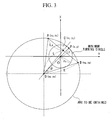
A process for obtaining the central coordinate D of the arc will be explained with reference to FIG. 3. In FIG. 3, an arc indicating a track of the jib point is shown which connects the initial position A and the target position B, and contacts the minimum turning circle of the crane.
-
A case is considered using an arbitrary point P (x, y) on the unknown arc, and a distance Lp between the point P and the point O.
-
Assuming that the radius of the arc to be obtained is R, the following formula (9) is obtained from the triangle ADC:
-
Also, the following formula (10) is obtained based on the equation of an arc:
-
Moreover, Lp can be expressed as the following formula (11) from FIG. 3:
-
Here, as shown in FIG. 3, the position of the point P at which Lp becomes minimum is a point a which the straight line connecting the point D and O meets the arc. Accordingly, assuming that the minimum value of L
P is Lp
min. then,
-
Since L
pmin must be equal to r
0 to contact the minimum turning circle when the straight line connecting the points D and O meets the arc, L
pmin can be expressed as the following formula (13):
-
By arranging the formula (13), and taking a square and rearranging the result obtained, the following formula (14) is obtained:
where α and β express the same formula as the above mentioned α and β, and can be obtained as a numerical value by a substitution with a known value.
-
Then, squaring the right hand side item and the left side item and rearranging the equation (13), the following equation (15) can be obtained.
where γ, δ, and ε express the same formula as the above-mentioned γ, δ, and ε, and can be obtained as a numerical value by a substitution with a known value.
-
Accordingly, the distance L between the point OD can be derived as a solution for a secondary equation. Thus, L can be expressed as the following formula (16) taking into account the fact that L is a positive value:
-
Using the distance L between the points O and D obtained by the above formula (16), the coordinate of the point D is determined. Since the coordinate of the point D is as the following formula (17) from FIG. 3:
the coordinate of the point D, which is the central coordinate of the arc can be obtained by substituting L with the formula (17).
-
As explained above, each of the formula explained above is obtained by determining the point C, which is a midpoint between the initial position A and the target position B, and the presence of the point D, which is the center of the arc to be obtained, on a perpendicular with respect to the straight line connecting A and B passing through the point C.
-
According to the above method, since it become possible to readily obtain the coordinate of the pint D and the radius R of the arc, etc., by determining the distance between the midpoint C with respect to the initial position A and the target position B, and the point D which is the center of the arc. Accordingly, it becomes possible to clearly define the arc-shaped track, and to move the jib point along the track.
-
The seventh aspect of the present invention also provides a method for operating a crane provided with a jib having a jib point from which a cargo is hung via a rope member, the cargo being moved from an initial position to a target position to carry out a cargo handling operation, comprising the steps of: operating a linear track connecting the initial position and the target position for the cargo, and carrying out a method for operating a crane according to one of the above-mentioned first to third aspects of the invention if it is determined that the operated linear track does not interfere with the minimum turning circle.
-
According to the above method for operating a crane, a linear track connecting the initial position and the target position is computed by the operation. Then, it is determined whether the linear track obtained by the operation interferes with the minimum turning circle.
-
If it is determined that the linear track does not interfere with the minimum turning circle, i.e., the linear track does not pass through the minimum turning circle, the linear track is recognized as a suitable track for transferring the cargo, and the jib point is moved along the linear track so that the hoisted cargo is transferred from the initial position to the target position.
-
Also, when the jib point is moved along the linear track, the crane is operated under the swing stop control for the hoisted cargo in order to eliminate the swing of the cargo in the moving direction while obtaining the actual change in the length of the rope member.
-
Since the linear track connecting the initial position and the target position for the cargo is operated, and a method for operating a crane according to one of the above-mentioned first to third aspects of the invention is carried out if it is determined that the operated linear track does not interfere with the minimum turning circle, an operation of the crane is selected which is the shortest among the various transfer tracks and from which the swing in the moving direction is removed. Accordingly, it becomes possible to quickly move the hoisted cargo, and the efficiency in the cargo handling operation is improved.
-
The eighth aspect of the present invention also provides a method for operating a crane provided with a jib having a jib point from which a cargo is hung via a rope member, the cargo being moved from an initial position to a target position to carry out a cargo handling operation, comprising the steps of: operating a linear track connecting the initial position and the target position for the cargo, and carrying out a method for operating a crane according to one of the fourth to sixth aspects of the invention if it is determined that the operated linear track interferes with the minimum turning circle.
-
According to the above method for operating a crane, a linear track connecting the initial position and the target position is computed by the operation. Then, it is determined whether the linear track obtained by the operation interferes with the minimum turning circle.
-
If it is determined that the linear track interferes with the minimum turning circle, i.e., the linear track passes through the minimum turning circle, the linear track is moved along the arc-shaped track explained in the above fourth to sixth aspects of the invention. Accordingly, the hoisted cargo is moved from the initial position to the target position along the arc-shaped track while being affected by a minimum centrifugal force.
-
Since the linear track connecting the initial position and the target position for the cargo is operated, and a method for operating a crane according to one of the above-mentioned fourth to sixth aspects of the invention is carried out if it is determined that the operated linear track interferes with the minimum turning circle, it becomes possible to move the hoisted cargo along the continuous arc-shaped track with a minimum centrifugal force applied to the cargo while clearing the restriction on the mechanical structure.
-
The ninth aspect of the present invention also provides a method for operating a crane provided with a jib having a jib point from which a cargo is hung via a rope member, the cargo being moved from an initial position to a target position to carry out a cargo handling operation, comprising the steps of: operating a linear track connecting the initial position and the target position for the cargo, carrying out a method for operating a crane according to one of the first to third aspects of the invention if it is determined that the operated linear track does not interfere with the minimum turning circle, and carrying out a method for operating a crane according to one of the fourth to sixth aspects of the invention if it is determined that the operated linear track interferes with the minimum turning circle.
-
According to the above method for operating a crane, a linear track connecting the initial position and the target position is computed by the operation. Then, it is determined whether the linear track obtained by the operation interferes with the minimum turning circle.
-
If it is determined that the linear track does not interfere with the minimum turning circle, i.e., the linear track does not pass through the minimum turning circle, the linear track is recognized as a suitable track for transferring the cargo, and the jib point is moved along the linear track so that the hoisted cargo is transferred from the initial position to the target position.
-
Also, when the jib point is moved along the linear track, the crane is operated under the swing stop control for the hoisted cargo in order to eliminate the swing of the cargo in the moving direction while obtaining the actual change in the length of the rope member.
-
On the other hand, if it is determined that the linear track interferes with the minimum turning circle, i.e., the linear track passes through the minimum turning circle, the linear track is moved along the arc-shaped track explained in the above fourth to sixth aspects of the invention. Accordingly, the hoisted cargo is moved from the initial position to the target position along the arc-shaped track.
-
Since the linear track connecting the initial position and the target position for the cargo is operated, and a method for operating a crane according to one of the above-mentioned first to third aspects of the invention is carried out if it is determined that the operated linear track does not interfere with the minimum turning circle, and a method for operating a crane according to one the above-mentioned fourth to sixth aspects of the invention is carried out if it is determined that the operated linear track interferes with the minimum turning circle, it becomes possible to transfer the hoisted cargo using a most suitable transfer track under the situation. When the hoisted cargo is linearly moved, the swing of the hoisted cargo is eliminated, and when the cargo is moved along the arc track, the centrifugal force applied to the cargo is prevented so that the moving rate of the jib point is increased to realize a high workability for the loading operation of the cargo.
-
The tenth aspect of present invention provides a control device for a crane which carries out a handling operation for a cargo connected to a rope member hung from a jib point of a jib provided with the crane, the cargo being moved from an initial position to a target position, the control device comprising: a rope length change obtaining unit which obtains a change in an actual length of the rope member; a jib point acceleration pattern operation unit which sets a hypothetical length of the rope member, operates a hypothetical acceleration pattern for swing angle of the rope member for a case where the cargo is to be stopped at the target position provided that the hypothetical length of the rope member does not change and that the cargo is linearly moved from the initial position to the target position, and operates an acceleration pattern for the jib point taking into account the change in the actual length of the rope member obtained by the rope length change obtaining unit so that an acceleration pattern for swing angle of the rope member matches the operated hypothetical acceleration pattern; and a linear operation command unit which linearly moves the jib point based on the jib point acceleration pattern operation unit.
-
According to the above control device for a crane which is provided with each of the above units, the hypothetical acceleration pattern is derived by the jib point acceleration pattern operation unit so that the cargo reaches from the initial position to the target position while a hypothetical pendulum having a hypothetical rope length returns to a lowest point from the lowest point. Then, the jib point acceleration pattern is operated so that the acceleration pattern of a swing angle of the rope member having an actual length obtained by the rope length change obtaining unit matches the above-mentioned hypothetical acceleration pattern.
-
In this manner, the jib point acceleration pattern by which the swing of the cargo is stopped at the target position is operated, and a command value for the linear operation command unit is output based on the operation result so that the actual movement of the jib point is controlled to stop the swing of the hoisted cargo.
-
Note that this is particularly useful when the jib point is linearly moved, and the swing of the hoisted cargo in the moving direction can be securely stopped.
-
According to the above control device, it becomes possible to eliminate the swing in the moving direction, which may be caused when the cargo is linearly transferred, regardless of the change in the length of the rope member. Therefore, it becomes possible for an operator to manually operated the crane, and the flexibility in the operation of the crane is increased. Also, in this way it becomes possible to transfer the cargo to the target position reliably and safely. Moreover, since the crane is controlled to stop the swing of the cargo, the labor for the operator is reduced. Furthermore, the efficiency in a cargo handling process may be improved since the cycle time required for repeatedly moving a cargo is shortened.
-
The eleventh aspect of the present invention also provides a control device for a crane which carries out a handling operation for a cargo connected to a rope member hung from a jib point of a jib provided with the crane, the cargo being moved from an initial position to a target position, the control device comprising: an arc operation command unit which controls a revolution operation of the crane and a hoisting operation of the jib along an arc shaped curve connecting the initial position and the target position.
-
According to the above control device for a crane, the jib point follows the arc-shaped track from the initial position to the target position by the arc operation command unit, and the hoisted cargo is transferred along the arc-shaped track. In order to move the jib point along the arc, it is necessary that at least a hoisting operation of the jib and a revolution operation of the crane be performed independently from each other at the same time, and the arc operation command unit orders these operations.
-
Note that it is preferable that the arc-shaped track ordered by the arc operation command unit to the crane have a large radius of curvature.
-
Since the control device for a crane includes the arc operation command unit which controls a revolution operation of the crane and a hoisting operation of the jib along an arc shaped curve connecting the initial position and the target position, it becomes possible to move the hoisted cargo from the initial position to the target position along a large arc avoiding the minimum turning circle. In this manner, the centrifugal force acting on the hoisted cargo is reduced, and the cargo can be quickly transferred to the target position. Also, since the centrifugal force is reduced, it becomes possible to decrease the swing of the hoisted cargo, and hence to reduce the labor of the operator. Moreover, since there is no discontinuous points on the transfer track, complicated control is not necessary to stop the swing of the cargo, and hence, the swing stop control can be simplified.
-
The twelfth present invention also provides a control device for a crane which carries out a handling operation for a cargo connected to a rope member hung from a jib point of a jib provided with the crane, the cargo being moved from an initial position to a target position, the control device comprising: a track determination unit which operates a linear line connecting the initial position and the target position, and outputs a positional relationship with respect to a minimum turning circle of the crane, a rope length change obtaining unit which obtains a change in an actual length of the rope member; a jib point acceleration pattern operation unit which sets a hypothetical length of the rope member, operates a hypothetical acceleration pattern for swing angle of the rope member for a case where the cargo is to be stopped at the target position provided that the hypothetical length of the rope member does not change and that the cargo is linearly moved from the initial position to the target position, and operates an acceleration pattern for the jib point taking into account the change in the actual length of the rope member obtained by the rope length change obtaining unit so that an acceleration pattern for swing angle of the rope member matches the operated hypothetical acceleration pattern; a linear operation command unit which linearly moves the jib point based on the jib point acceleration pattern operation unit; and an arc operation command unit which controls a revolution operation of the crane and a hoisting operation of the jib along an arc shaped curve connecting the initial position and the target position, wherein the track determination unit selects one of the linear operation command unit and the arc operation command unit for an operation of the crane.
-
According to the above control device for a crane, the track determination unit determines the track for transferring the cargo from the initial position to the target position, and if it is determined that a linear movement is possible, it selects the linear operation command unit to linearly move the jib point.
-
On the other hand, if the track determination unit determines that it is not possible to linearly move the cargo from the initial position to the target position, i.e., if it is determined that the linear track connecting the initial position to the target position passes through the minimum turning circle, the track determination unit selects the arc operation command unit for the operation of the crane. Then, the arc operation command unit moves the jib point along an arc-shaped track which avoids the minimum turning circle.
-
According to the above control device for a crane, a transfer track which is most suitable for moving the jib point from the initial position to the target position is selected. When the linear movement is selected, the swing of the hoisted cargo is eliminated, and when the arc-shaped track is selected, the centrifugal force applied to the cargo is reduced. In both cases, the moving range of the jib point is increased to realize high efficiency in the cargo handling operation.
-
The thirteenth aspect of the present invention provides a crane which carries out a handling operation for a cargo connected to a rope member hung from a jib point of a jib provided with the crane, the cargo being moved from an initial position to a target position, the crane comprising: a control device for a crane as set forth in one of the above-mentioned tenth to twelfth aspects of the present invention.
-
According to the above crane, a track for a cargo by which the swing of the cargo is eliminated or the centrifugal force applied to the cargo is minimized, is selected among various tracks for transferring the cargo from the initial position to the target position, and a cargo handling operation is carried out. Also, according to the above crane, the moving range of the jib point can be increased by stopping the swing of the cargo, and it becomes possible to provide a crane which is capable of contributing the improvement in workability as well as the reduction in the labor of the operator.
BRIEF DESCRIPTION OF THE DRAWINGS
-
Some of the features and advantages of the invention having been described, others will become apparent from the detailed description which follows, and from the accompanying drawings, in which:
- FIG. 1 is a schematic diagram showing a mobile harbor crane according to an embodiment of the present invention;
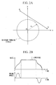
- FIG. 2A is a diagram showing a linear track of a jib point of the mobile harbor crane according to the embodiment of the present invention in relation to a minimum turning circle of the crane;
- FIG. 2B is a graph showing the relationship between the moving rate of the jib point during the linear movement thereof in relation to time;
- FIG. 3 is a diagram for explaining an arc-shaped track and a method for obtaining the track of the jib point of the mobile harbor crane according to the embodiment of the present invention;
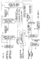
- FIG. 4 is a flowchart showing the flow of command signals in a control unit of the mobile harbor crane according to the embodiment of the present invention;
- FIG. 5A is a diagram showing a conventional polygonal movement or linear movement of a jib point of a crane;
- FIG 5B is a diagram showing a track of a jib point using a tangent of a minimum turning circle;
- FIG. 6A is a graph showing a relationship between the moving rate of a jib point and time, and between a swing angle of a hoisted cargo with respect to a vertical direction and time for explaining a swing stop pattern of a hoisted cargo in a conventional crane; and
- FIG. 6B is a schematic diagram showing a model of a swinging pendulum for explaining a swing stop pattern of a hoisted cargo in a conventional crane.
DETAILED DESCRIPTION OF THE INVENTION
-
The invention summarized above and defined by the enumerated claims may be better understood by referring to the following detailed description, which should be read with reference to the accompanying diagrams. This detailed description of particular preferred embodiments, set out below to enable one to build and use one particular implementation of the invention, is not intended to limit the enumerated claims, but to serve as specific examples thereof.
-
FIG. 1 is a diagram showing a schematic structure of a mobile harbor crane 1 according to an embodiment of the present invention.
-
Also, FIGS. 2A and 2B and FIG. 3 are diagrams showing tracks of a jib point H of the mobile crane. FIG. 2A is a plan view indicating a linear movement of the jib point H. FIG. 2B is a pattern diagram showing the speed of the crane during operation thereof. FIG. 3 is a plan view showing an arc track of the jib point H and a manner of obtaining the track. Also, FIG. 4 is a flowchart showing the flow of command signals from a control unit 10 when swing of a cargo is stopped.
-
The numeral 1 shown in FIG. 1 indicates a mobile harbor crane (hereinafter also simply referred to as a "body") which may be suitably used in a harbor facility as harbor equipment. The body 1 of the mobile harbor crane mainly includes a carrier frame 11 provided with a plurality of outriggers 12, a revolving frame 13 and a main frame 14, each of which is mounted on the carrier frame 11, and a jib 2 attached to the main frame 14.
-
The carrier frame 11 secures the stability of the body 1 by means of the plurality of the outriggers 12, each of which protrude from both side of the carrier frame 11 in a vertical direction with respect to the longitudinal direction thereof.
-
When the outriggers 12 are accommodated in the carrier frame 11, the crane can move around the yard of the harbor by means of wheels (not shown in the figure).
-
Swing bearings of circular shape (not shown in the figure) are.provided at substantially the center portion of the carrier frame 11, and the revolving frame 13 is mounted on the carrier frame 11 via the swing bearings. Gear racks are formed around the swing bearings and pinions (not shown in the figures), which are attached to a revolving driving unit (not shown in the figures), are engaged with the pinions. The revolving driving unit is attached to the revolving frame 13 side.
-
Accordingly, the revolving frame 13 is rotatable 360° around the center of the swinging bearings due to the rotation of the pinions. Note that the center of the swinging bearings means the rotation center O, and indicates the center of the operating radius of the crane carrying out the handling operation of a cargo.
-
Also, a revolution angle detection device 5a, which detects the revolution direction of the revolving frame 13 with respect to the carrier frame 11 is disposed in the vicinity of the revolving center O of the revolving frame 13. The revolution angle detection device 5a is connected to the control unit 10, which will be described later, by a cable indicated by dotted lines.
-
On the revolving frame 13, the main frame 14, a winch 4, a cylinder 6, and an operation room (not shown in the figure) are mainly provided. The main frame 14 rotatably supports a base end portion of the jib 2. The winch 4 winds up a rope 3 (also referred to as a "wire") connected to a hoisted cargo G. The cylinder 6 hoists the jib 2, and an operator occupies the operation room to perform crane operations.
-
The winch 4 is provided with an encoder 4a (means for obtaining a change in rope length) which detects a state of the length of the rope 3. The encoder 4a is connected to the control unit 10, which will be described later, by a cable indicated by the dotted lines.
-
The main frame 14 has a truss structure in which a plurality of rod type members are combined. The base end portion of the jib 2 (the left hand side in the figure) is attached to substantially the middle position of the main frame 14 via jib foot pins (not shown in the figures). A hoisting angle detection device 2a, which detects the hoisting angle of the jib 2, is disposed at a side of the jib foot pin or of the jib 2. The hoisting angle detection device 2a is connected to the control unit 10, which will be described later, by the cable indicated by the dotted lines.
-
The jib 2 has a long shape with a truss structure, and the base end portion of the jib 2 is rotatably supported by the main frame 14 as explained above. Also, an end portion of the cylinder 6 at the rod side is rotatably attached to an underside position of the base end portion of the jib 2 slightly shifted towards the jib point side via pins (not shown in the figure). In this manner, the jib 2 is supported. Another end portion of the cylinder 6 at the bottom side is rotatably attached to a front portion of the revolving frame 13 via pins (not shown in the figures).
-
The jib 2 is hoisted with respect to the jib foot pin, which functions as the center, by extension and retraction operations of the cylinder 6, and the jib operating radius based on the jib point H is determined.
-
An end of the rope 3 is connected to a hook (not shown in the figures) for hoisting a cargo G, and the rope is hung from the jib point H towards the cargo G. Also, the other end of the rope 3 is wound up by the winch 4 provided on the revolving frame 13. The cargo G may be moved up by the winding operation of the rope 3 utilizing a rotary operation of the winch 4. Also, the hoisted cargo G may be moved downwardly by rotating the winch 4 in the reverse direction.
-
Also, a control device for controlling the operation of the body 1 includes, in addition to the control unit 10, at least the above-mentioned revolution angle detection device 5a, the hoisting angle detection device 2a, and the encoder 4a.
-
Next, loading and unloading operations for the cargo G will be explained using FIG. 2 and 3 with reference to FIG. 1.
-
The operator for operating the crane inputs positional information of the initial position A at which the cargo G is placed, and the target position B to which the cargo G is moved prior to starting to operate the crane. The operation for inputting each position may be carried out using an X-Y plane including the revolving center O of the body 1 as a reference point, and the operator inputs each position using an operation panel which is equivalent to the X-Y plane. In this operation, the positional information of the initial position A and the target position B is output to the control unit 10 of the crane.
-
When the initial position A and the target position B are input, each coordinate data is output to the control unit 10 to obtain a linear line connecting the positions A and B.
-
Then, it is determined whether the linear line passes over the minimum turning circle based on the arithmetic expressions. In order to determine whether the linear line passes over the minimum turning circle, for instance, a perpendicular is drawn from the revolving center O with respect to the straight line connecting the initial position A and the target position B, and it is determined that the distance between the intersection of the linear line and the straight line and the revolving center O is longer than the radius r0 of the minimum turning circle. Note that this determination is carried out by a coordinate transformation unit 50 (track determination means) provided in the control unit 10 shown in FIG. 4, which will be described later.
-
Also, the minimum turning circle means a circle having a radius r0 which indicates that the handling operation of a cargo is not possible within the circle due to the mechanical restriction of the crane, and which also indicates a movable range of the jib point H when the jib 2 is hoisted to the maximum degree.
-
Then, when it is determined that the linear line connecting the initial position A and the target position B does not pass through the minimum turning circle, the jib point H is linearly moved in order to transfer the cargo G along the linear line obtained as mentioned above and as shown in FIG. 2A.
-
Also, if it is determined that the linear line connecting the initial position A and the target position B passes through the minimum turning circle, an arc shaped transfer track as shown in FIG. 3 is selected as a track for the jib point H. This operation method will be described later in detail.
-
The linear movement of the jib point H may be carried out by coupling the hoisting motion of the jib 2 with the rotation of the revolving frame 13. In such a case, since the operator does not want an extreme change in the height of the cargo G by the hoisting operation of the jib 2, the operator also operates the winch 4 so as to maintain a constant height of the cargo G.
-
Moreover, the operator may additionally carry out a raising and lowering operations of the cargo G in order to avoid obstacles in the transfer path or to maintain a certain distance of the cargo G from the ground.
-
However, according to the method for linearly moving the cargo G of the present invention explained below, no centrifugal force or swing in the moving direction is applied to the cargo G even if a rotation operation of the crane is carried out, and it also becomes possible to move the cargo G using the shortest track. With regard to the swing of the cargo G in the moving direction, the moving rate of the jib point H is controlled so that the cargo G does not swing in accordance with the length of the rope 3.
-
Next, a control for stopping the swing of the hoisted cargo G in the moving direction of the jib point H will be explained with reference to the flowchart shown in FIG. 4.
-
First, the coordinates of the initial position A and the target position B are transformed into coordinates for practice by means of the coordinate transformation unit 50.
-
Then, a standard rope length λ0 (a virtual rope length) which becomes a base for a virtual pendulum, is obtained at a standard rope length setting unit 51 by taking into account the acceleration limit, and the speed limit derived from the mechanical structure of the body 1, and the actual rope length λ. The result obtained is output to a standard rope length swing stop pattern formation unit 52. Note that the actual rope length λ is also directly output to an actual rope length acceleration command computation unit 54 (a jib point acceleration pattern computation means) which will be explained later. Also, the obtained standard rope length λ0 is directly output to the actual rope length acceleration command computation unit 54.
-
In the standard rope length swing stop pattern formation unit 52 to which the coordinates for computation and the standard rope length λ0 are input, a swing stop pattern (virtual acceleration pattern) by which the cargo G is moved from the initial position A to the target position B during the period in which the virtual pendulum at the standard rope length λ0 returns to the zero point from the zero point.
-
Here, the acceleration ako of the virtual pendulum at the standard rope length λ0 is obtained, and this result is directly output to the actual rope length acceleration command computation unit 54, and is output to the standard rope length swing angle computation unit 53. Methods for obtaining the acceleration ako and the standard rope length λ0 will be explained later in the section of computation processes.
-
The acceleration ako of the virtual pendulum at the standard rope length λ0 input into the standard rope length swinging angle computation unit 52 is used to obtain the swinging angle θ of the virtual pendulum at the standard rope length λ0, and this is output to the actual rope length acceleration command computation unit 54.
-
Further, the velocity v and the acceleration κ of the actual length of the rope are obtained by means of the time measurement of the encoder 4a, which measures the actual rope length, and the result is output to the actual rope length acceleration command computation unit 54.
-
Also, the swinging angular velocity ω of the cargo G may be obtained from the period T of the cargo G. That is, since the period T can be obtained from the following equation (18):
the swinging angular velocity ω may be obtained from the following equation (19):
-
As explained above, since the standard rope length λ
0, the acceleration κ, the swinging angle θ, and the actual rope length λ, as well as the velocity ν and the acceleration κ at the actual rope length, and the swinging angular velocity ω of the cargo are input into the actual rope length acceleration
command computation unit 54, the jib point acceleration a
k can be obtained using the following equation (20) which is the same as the equation (1):
-
Note that the acceleration a
ko of the virtual pendulum may be obtained from the acceleration limit due to the mechanical structure of the crane and the actual rope length λ, and the above equation (20) can be expressed as the following equation (21) using a
max as the acceleration limit due to the mechanical structure, and
sf as a safety coefficient:
-
Accordingly, the acceleration ako of the virtual pendulum in the above equation (21) is defined, and by this definition of the acceleration ako, and the standard rope length λ0 of the virtual pendulum may be obtained based on the acceleration limit due to the mechanical structure amax. Although the rope length is not limited as above, it has an advantage of utilizing the performance of the crane to its maximum.
-
As explained above, according to the present invention, the acceleration command for the jib point H is obtained from time to time taking into account the actual length of the rope λ, which varies in accordance with the above equation (20). Accordingly, the velocity command for the jib point H can be obtained by integrating the acceleration command. Also, the positional command for the movement of the jib point H can be obtained by further carrying out the integration process.
-
Based on the obtained positional command, coordinate transformation is performed again on the X-Y plane showing the situation of the body 1 using a coordinate transformation unit 55 in order to output a revolution angle command and a hoisting angle command. The revolution angle command and the hoisting angle command are, of course, control commands that are obtained in relation to each other.
-
The revolution angle command is output to a revolution driving device with reference to the output value of the revolution angle detection device 5a so as to prompt the revolution operation of the revolving frame 13 which includes the jib 2 attached to the main frame 14. Also, the hoisting angle command is input to a coordinate transformation unit 56 for the length of the cylinder 6, and is converted into a length command for the cylinder 6 to prompt the expansion operation of the cylinder 6.
-
Next, the velocity pattern of the jib point H will be explained using an example. As shown in FIG. 2B, the swing period of the cargo is regarded as one unit during the acceleration, and the crane is operated in accordance with the acceleration pattern by which the swing of the cargo is stopped when the velocity becomes constant. If a hypothetical case is considered in which an unexpected lowering operation is carried out during the constant speed period, since the actual length of the rope 3 is varied as compared with an expected length thereof, the velocity pattern of the jib point H, i.e., the acceleration pattern, is changed accordingly.
-
The dotted line shown in the figure indicates a case where the change in the length of the rope 3 is known in advance in accordance with the hoisting of the jib 2. That is, the velocity pattern is almost the same as that at the start of acceleration. However, if there is ari unexpected operation during the constant speed period, the acceleration pattern and the velocity pattern of the jib point H are changed as shown in the solid line shown in FIG. 2B. Accordingly, the swing of the cargo is suppressed and the cargo is transferred to the target point B.
-
Also, since the length of the rope 3 is increased due to the unexpected lowering operation, the degree of swing of the hoisted cargo within one period is also increased. According to the present invention, however, the crane is controlled in accordance with the swinging angle of the cargo, and the swinging angle of the cargo is not changed as shown in the figure.
-
Next, a transfer track of the jib point H will be explained for the case where it is determined based on the operation that the straight line connecting the initial position A and the target position B passes through the minimum turning circle having the radius r0 using FIG. 3.
-
In FIG. 3, the point O (0, 0) indicates the revolution center, the circle including the point O indicates a minimum turning circle having the radius of r0, the coordinate of the initial position A is (XA, yA), the coordinate of the target position B is (XB, yB), and the coordinate of the middle point C between the point A and the point B is (xc, yc), the distance between the point A and the point C is LA, the radius of the arc is R, the coordinate of an arbitrary point P on the arc is (x, y), and ø indicates an angle between a perpendicular to the straight line connecting the point A and the point B, which passes through the point C, and the x axis.
-
Also, the distance between the point C and the point D is assumed to be L, and the distance between the point O and the point P is assumed to be Lp.
-
When it is determined by the above-mentioned operation that the straight line AB connecting the initial position A and the target position B passes through the minimum turning circle, the control unit 10 (refer to FIG. 1) starts operation to obtain an arc shaped track which connects the point A and the point B without passing through the minimum turning circle. Processes for moving the jib point H along the arc shaped tack will be explained.
-
As described in
claim 6 and the relevant sections thereof in this specification, if the coordinates, which are known, and the equation expressed by ø are substituted by the following equations (22)-(27):
then, the distance L between the point C and the above-mentioned point D can be obtained using the following equation (28):
-
On the other hand, the coordinate of the point D to be obtained can be expressed by the following formula (29):
-
Accordingly, the coordinate of D can be obtained by substituting L, which is obtained by the above formula (28) with the equation (29).
-
Also, the radius R of the arc to be obtained can be expressed using the following formula (30) based on FIG. 3:
-
Accordingly, in the above-explained manner, the radius R of the arc, and the center coordinate D of the arc with respect to the revolution center O can be obtained.
-
The operation (i.e., computing) explained above is carried out by an arc operation command unit 60 (an arc operation command means), and the results of the operation are input into the coordinate transformation unit 55 to control the rotation operation of the revolving frame 13, and the hoisting operation of the jib 2 at the same time. Of course, the command relating to the hoisting operation of the jib 2 is output by being converted into a length command for the cylinder 6 via the coordinate transformation unit 56 for the cylinder 6.
-
The jib point H is moved along the arc shown in FIG. 3 as the transfer track so that a handling operation of the cargo is carried out from the initial position A to the target position B.
-
In this embodiment, the arc shaped track for the cargo G touches the minimum turning circle only at a point and does not follow the minimum turning circle. That is, the arc shaped track has a radius R which is much larger than the radium r0. It is needless to say that the centrifugal force applied to the cargo G becomes smaller as the moving radius for the cargo G becomes larger.
-
Also, although the arc shaped movement of the jib point H is explained by obtaining an arc which contacts the minimum turning circle, the method for obtaining the arc shaped track is not limited to this, and can be obtained as described below.
-
It has been explained that the minimum turning circle having the radius r0 can be defined by the hoisting of the jib 2 at the maximum degree. That is, since the minimum turning circle indicates a near-limit of the moving range of the jib 2 due to the mechanical structure thereof, there is a possibility that an accurate operation of the jib 2 becomes difficult depending on the situation due to, for instance, stuck of the cylinder 6.
-
Also, when the cargo G is moved near to the ground, there is a possibility that the outriggers 12 (refer to FIG. 1) will interfere with the transfer track of the cargo G.
-
In order to avoid these problems, it is possible to assume a hypothetical circle having a radius larger than r0 outside the minimum turning circle, and to obtain an arc shaped track which contacts the hypothetical circle. In this manner, practically suitable and accurate loading and unloading operations for the cargo G can be carried out by substituting the radius r0 of the minimum turning circle with the radius of the above-mentioned hypothetical circle.
-
According to the method for operating the crane to move the jib point H of this embodiment of the present invention, a most suitable transfer track of the cargo G can be obtained from the initial position A and the target position B, and the workability in the loading and unloading operations can be improved.
-
Also, in the linear movement of the jib point H, the generation of swing of the hoisted cargo G can be suppressed to substantially zero regardless of the change in the length of the rope 3 due to the change in the acceleration. Accordingly, time required for stopping the swing of the cargo may be shortened, and the workability of the crane can be improved. Moreover, since the crane may be always operated in the vicinity of the acceleration limit due to the mechanical structure thereof, the cargo G may be transferred in a short amount of time while freely adjusting the height of the cargo G.
-
Furthermore, according to the present invention, the operator of the crane need not carry out an operation for stopping the swing of the cargo, or the labor necessary for such operation is significantly reduced. In addition, since the operator of the crane is free to carry out raising and lowering operations for the cargo G during the operation, a more appropriate handling operation for the cargo may be realized.
-
Also, as for the arc track of the jib point H, since the hoisted cargo G may be moved along a continuous arc shaped track having a large radius R, it becomes possible to minimize the centrifugal force applied to the cargo G, and also the revolving speed can be increased without applying complicated and rapid inertia to the cargo G. Accordingly, the workability in the handling operation of the cargo G can be improved.
-
Note that although an embodiment to which the present invention is applied to a mobile harbor crane 1 is explained above, it is possible to apply the present invention to all cranes which are provided with a jib having a revolving function.
-
Also, although a transfer track is explained for the case where the cargo G is hung from the jib point H, it is of course possible to apply the present invention to a guiding operation for a jib not carrying a cargo. This is because if a hanging member of the jib for carrying a cargo swings, this interferes with the handling operation, and it is necessary to stop swing of the hanging member.
-
According to the above-mentioned case, time is reduced in a repeated operation of unloading the cargo G at the target point B and moving the jib back to the initial position A to load another cargo.
-
Having thus described several exemplary embodiments of the invention, it will be apparent that various alterations, modifications, and improvements will readily occur to those skilled in the art. Such alterations, modifications, and improvements, though not expressly described above, are nonetheless intended and implied to be within the spirit and scope of the invention. Accordingly, the invention is limited and defined only by the following claims and equivalents thereto.
-
Further embodiments are named in the following:
- 1. A method for operating a crane provided with a jib having a jib point from which a cargo is hung via a rope member, said cargo being moved from an initial position to a target position to carry out a cargo handling operation, said method comprising:
- a hypothetical rope length setting step in which a hypothetical length of said rope member is set;
- a hypothetical acceleration pattern operation step in which a hypothetical acceleration pattern for a swing angle of said rope member is operated for a case where the swing of said cargo is to be stopped at the target position provided that the hypothetical length of said rope member does not change and that said cargo is linearly moved from the initial position to the target position;
- a rope length change obtaining step in which a change in an actual length of said rope member is obtained;
- a jib point acceleration pattern operation step in which an acceleration pattern for said jib point is operated taking into account the change in the actual length of said rope member obtained in the rope length change obtaining step so that an acceleration pattern for swing angle of said rope member matches the hypothetical acceleration pattern obtained in the hypothetical acceleration pattern operation step; and
- a jib moving step in which said jib point is linearly moved based on results obtained in the jib point acceleration pattern operation step.
- 2. A method for operating a crane according to 1, wherein said hypothetical rope length is set based on a maximum acceleration for linearly moving said jib point, said maximum acceleration being determined based on performance of said crane.
- 3. A method for operating a crane according to 1, wherein a jib point acceleration ak in the jib point acceleration pattern operation step is expressed by the following formula:
where λ0 is the hypothetical rope length, λ is the length of said rope member, ν is a velocity of said rope member, κ is an acceleration of said rope member, ako is a jib point hypothetical acceleration in the hypothetical acceleration pattern operation step, θ is a swing angle of said cargo, ω is a swing angular velocity of said cargo, and g is gravitational acceleration. - 4. A method for operating a crane provided with a jib having a jib point from which a cargo is hung via a rope member, said cargo being moved from an initial position to a target position to carry out a cargo handling operation, said method comprising the step of:
- transferring said cargo along an arc-shaped curve connecting the initial position and the target position, the arc-shaped curve not passing through a minimum turning circle which defines a range that a handling operation for said cargo is not possible due to a mechanical restriction of said crane.
- 5. A method for operating a crane according to 4, wherein the arc-shaped curve contacts the minimum turning circle at one point.
- 6. A method for operating a crane according to , 5, wherein a transfer track of said cargo is projected onto an X-Y plane, and assuming that a coordinate of a revolution center of said crane is O (0, 0), a coordinate of the initial position A is (XA, yA), a coordinate of the target position B is (xB, yB), a coordinate of a middle point C between the point A and the point B is (xC, yC), a distance between the point A and the point C is LA, an angle between a perpendicular with respect to a straight line connecting the point A and the point B, which passes through the point C, and an x axis is φ , a radius of the minimum turning circle of said crane is r0, a coordinate of a point D which is the center of said arc-shaped curve is D (xD, yD), and the distance between the point C and the point D is L,
then, α, β, γ, δ, and ε are defined based on the following formulas:
and, the distance L is expressed by the following formula:
to obtain the coordinate D (xD, yD) of the point D using the following equation: - 7. A method for operating a crane provided with a jib having a jib point from which a cargo is hung via a rope member, said cargo being moved from an initial position to a target position to carry out a cargo handling operation, said method comprising the steps of:
- operating a linear track connecting the initial position and the target position for said cargo, and
- carrying out a method for operating a crane according to any one of 1-3 if it is determined that the operated linear track does not interfere with the minimum turning circle.
- 8. A method for operating a crane provided with a jib having a jib point from which a cargo is hung via a rope member, said cargo being moved from an initial position to a target position to carry out a cargo handling operation, said method comprising the steps of:
- operating a linear track connecting the initial position and the target position for said cargo, and
- carrying out a method for operating a crane according to any one of 4-6 if it is determiner that the operated linear track interferes with the minimum turning circle.
- 9. A method for operating a crane provided with a jib having a jib point from which a cargo is hung via a rope member, said cargo being moved from an initial position to a target position to carry out a cargo handling operation, said method comprising the steps of:
- operating a linear track connecting the initial position and the target position for said cargo,
- carrying out a method for operating a crane according to any one of 1-3 if it is determined that the operated linear track does not interfere with the minimum turning circle, and
- carrying out a method for operating a crane according to any one of 4-6 if it is determined that the operated linear track interferes with the minimum turning circle.
- 10. A control device for a crane which carries out a handling operation for a cargo connected to a rope member hung from a jib point of a jib provided with said crane, said cargo being moved from an initial position to a target position, said control device comprising:
- a rope length change obtaining unit which obtains a change in an actual length of said rope member;
- a jib point acceleration pattern operation unit which sets a hypothetical length of said rope member, operates a hypothetical acceleration pattern for swing angle of said rope member for a case where said cargo is to be stopped at the target position provided that the hypothetical length of said rope member does not change and that said cargo is linearly moved from the initial position to the target position, and operates an acceleration pattern for said jib point taking into account the change in the actual length of said rope member obtained by the rope length change obtaining unit so that an acceleration pattern for swing angle of said rope member matches the operated hypothetical acceleration pattern; and
- a linear operation command unit which linearly moves said jib point based on the jib point acceleration pattern operation unit.
- 11. A control device for a crane which carries out a handling operation for a cargo connected to a rope member hung from a jib point of a jib provided with said crane, said cargo being moved from an initial position to a target position, said, control device comprising:
- an arc operation command unit which controls a revolution operation of said crane and a hoisting operation of said jib along an arc shaped curve connecting the initial position and the target position.
- 12. A control device for a crane which carries out a handling operation for a cargo connected to a rope member hung from a jib point of a jib provided with said crane, said cargo being moved from an initial position to a target position, said control device comprising:
- a track determination unit which operates a linear line connecting the initial position and the target position, and outputs a positional relationship with respect to a minimum turning circle of said crane,
- a rope length change obtaining unit which obtains a change in an actual length of said rope member;
- a jib point acceleration pattern operation unit which sets a hypothetical length of said rope member, operates a hypothetical acceleration pattern for swing angle of said rope member for a case where said cargo is to be stopped at the target position provided that the hypothetical length of said rope member does not change and that said cargo is linearly moved from the initial position to the target position, and operates an acceleration pattern for said jib point taking into account the change in the actual length of said rope member obtained by the rope length change obtaining unit so that an acceleration pattern for swing angle of said rope member matches the operated hypothetical acceleration pattern;
- a linear operation command unit which linearly moves said jib point based on the jib point acceleration pattern operation unit; and
- an arc operation command unit which controls a revolution operation of said crane and a hoisting operation of said jib along an arc shaped curve connecting the initial position and the target position, wherein
- said track determination unit selects one of said linear operation command unit and said an arc operation command unit for an operation of said crane.
- 13. A crane which carries out a handling operation for a cargo connected to a rope member hung from a jib point of a jib provided with said crane, said cargo being moved from an initial position to a target position, said crane comprising:
- a control device for a crane as set forth in any one of 10-12.