EP1661777A1 - Seat belt retractor with a load limiter - Google Patents
Seat belt retractor with a load limiter Download PDFInfo
- Publication number
- EP1661777A1 EP1661777A1 EP06001477A EP06001477A EP1661777A1 EP 1661777 A1 EP1661777 A1 EP 1661777A1 EP 06001477 A EP06001477 A EP 06001477A EP 06001477 A EP06001477 A EP 06001477A EP 1661777 A1 EP1661777 A1 EP 1661777A1
- Authority
- EP
- European Patent Office
- Prior art keywords
- seat belt
- torque rod
- gear
- rotation
- belt reel
- Prior art date
- Legal status (The legal status is an assumption and is not a legal conclusion. Google has not performed a legal analysis and makes no representation as to the accuracy of the status listed.)
- Granted
Links
Images


Classifications
-
- B—PERFORMING OPERATIONS; TRANSPORTING
- B60—VEHICLES IN GENERAL
- B60R—VEHICLES, VEHICLE FITTINGS, OR VEHICLE PARTS, NOT OTHERWISE PROVIDED FOR
- B60R22/00—Safety belts or body harnesses in vehicles
- B60R22/34—Belt retractors, e.g. reels
- B60R22/341—Belt retractors, e.g. reels comprising energy-absorbing means
- B60R22/3413—Belt retractors, e.g. reels comprising energy-absorbing means operating between belt reel and retractor frame
-
- B—PERFORMING OPERATIONS; TRANSPORTING
- B60—VEHICLES IN GENERAL
- B60R—VEHICLES, VEHICLE FITTINGS, OR VEHICLE PARTS, NOT OTHERWISE PROVIDED FOR
- B60R22/00—Safety belts or body harnesses in vehicles
- B60R22/28—Safety belts or body harnesses in vehicles incorporating energy-absorbing devices
- B60R2022/286—Safety belts or body harnesses in vehicles incorporating energy-absorbing devices using deformation of material
- B60R2022/287—Safety belts or body harnesses in vehicles incorporating energy-absorbing devices using deformation of material of torsion rods or tubes
-
- B—PERFORMING OPERATIONS; TRANSPORTING
- B60—VEHICLES IN GENERAL
- B60R—VEHICLES, VEHICLE FITTINGS, OR VEHICLE PARTS, NOT OTHERWISE PROVIDED FOR
- B60R22/00—Safety belts or body harnesses in vehicles
- B60R22/28—Safety belts or body harnesses in vehicles incorporating energy-absorbing devices
- B60R2022/288—Safety belts or body harnesses in vehicles incorporating energy-absorbing devices with means to adjust or regulate the amount of energy to be absorbed
Landscapes
- Engineering & Computer Science (AREA)
- Mechanical Engineering (AREA)
- Automotive Seat Belt Assembly (AREA)
Abstract
Description
- The present invention relates to a seat belt retractor with a load limiter.
- A seat belt system prevents a vehicle occupant from sustaining injuries in a crash as a result of colliding with the interior structure of the vehicle. In a crash, a locking device locks the seat belt webbing such that further extraction of the seat belt webbing due to the forces acting upon the vehicle occupant is prevented and the vehicle occupant is held in the seat through the belt force achieved by the locking.
- In known seat belt retractors, it has been shown to be a disadvantage that the belt force is independent of the characteristics of a particular crash and/or the vehicle occupant. In these cases the belt force is determined on the basis of mean values, for instance the average weight of vehicle occupants or mean crash values. If the vehicle occupant, however, weighs less than the average weight, even though the belt force indeed is able to prevent the person from sustaining an injury due to colliding with a component inside the vehicle, the belt force can be too great for this person and cause him/her harm.
- A seat belt retractor according to the present invention has a locking device with at least one gear that is reversibly lockable by at least one lock operating device, and has at least one energy absorbing device. Therefore, the belt force resulting from the locking of the seat belt retractor in a crash can follow the crash pulse, or that parameters dependent on people, such as for instance the weight of the vehicle occupant, can be taken into account. In particular it is possible, after an initially high level of belt force, to decrease the latter to a reduced level. The seat belt retractor can be an automatic retractor.
-
- Fig. 1 is a diagrammatic longitudinal cross-sectional view of a first embodiment not part of the present invention.
- Fig. 2 is a diagrammatic longitudinal cross-sectional view of a second embodiment not according to the present invention.
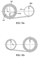
- Figs. 3a and 3b are diagrammatic radial cross sectional views of an embodiment of the present invention.
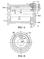
- Fig. 4 is a diagrammatic longitudinal cross-sectional view of a fourth embodiment not according to the present invention.
- Fig. 5 is a top view of a section along line 5-5 in Fig. 4.
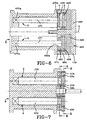
- Fig. 6 is a diagrammatic longitudinal cross-sectional view of a fifth embodiment not according the present invention.
- Fig. 7 is a diagrammatic longitudinal cross-sectional view of a sixth embodiment not according the present invention.
- Fig. 8 is an enlarged radial cross sectional view of the sixth embodiment taken along line 8-8 in Fig. 7.
- Fig. 9 is an enlarged radial cross sectional view of the sixth embodiment taken along line 9-9' in Fig. 7.
- The invention will be described in more detail with reference to the figures. In this context it must be noted that used terms such as "left", "right", "below" and "above" refer to the figures with normally legible figure designations.
- Fig. 1 is a diagrammatic longitudinal cross-sectional view of a first embodiment of a seat belt retractor not according to the invention. A seat belt retractor according to the invention has a belt reel W for the winding and unwinding of a seat belt webbing, which is not shown in detail. The belt reel has an axis of rotation that is indicated by the letter "A ".
A locking device for the locking of the belt reel W against further rotation is formed by at least one gear G, that can be locked by at least one lock operating device, and an energy absorbing device E. The gear can be any suitable gear, such as a single-stage spur wheel gear. A seat belt retractor according to the invention can be provided with a pre-locking device to pre-lock the belt reel against further rotation and to adjust the belt reel locking effected by the locking device. - The belt reel W comprises a hollow cylinder-
like member 10 that is preferably made of metal. At the left andright ends like member 10 is in each case provided with aflange left end 12a of thebelt reel 10 is closed, while theright end 12b comprises an opening 16, in which at least part of the gear G is arranged. Theright flange 14b of thebelt reel 10 displays in the represented cross sectional view of Fig. 1 the shape of an upside down "L", whereby on the inside of the horizontal leg of the letter "L" aninternal gear toothing 18 is provided. This internal gear toothing 18 or theright flange 14b of the hollow cylinder-like member 10 of the belt reel W forms a ring gear for the gear G. - Coaxially to the axis of rotation A of the belt reel W, inside of the belt reel W, an energy absorbing device E that is a
torque rod 20 is arranged. At itsleft end 20a, thetorque rod 20 is non-rotatably connected to the belt reel W at the latter'sleft end 12a. The non-rotatable connection between thetorque rod 20 and theleft end 12a of the belt reel W can for instance be achieved in that theleft end 20a of thetorque rod 20 is a square that is pressed into a correspondingly designed, not further represented, opening. Theright end 20b of thetorque rod 20 forms part of the gear G. Alternatively, the end of the energy absorbing device that is a component of the gear is non-rotatably connected with a sun wheel of a planetary gear. Preferably, in all embodiments of the invention being disclosed herein, each torque rod along most of its length has a circular cross section. In the case of two energy-absorbing devices that are both two-torque rods, there is the possibility, for the adjustment of the force gradient by designing the torque rods with the same diameter or with different diameters. There is also the possibility of manufacturing the torque rods out of different materials, so that various force gradients can be elicited. - The gear G can be a control gear that allows the control process to be triggered by various events and/or means. The control gear may be an infinitely variable control gear wherein a continuous, automatic adjustment of the belt force is enabled. Alternatively, the control gear may be a graduated control gear with at least two control grades that can be progressively enabled. An example of a graduated control gear would be a planetary gear. If the gear is a planetary gear, the ring gear and/or the sun wheel and/or the planet wheel carrier of the planetary gear can be locked in each case by a lock-operating device. In principle this results in the possibility of being able to obtain various force gradients. There is also the possibility of using one and the same planetary gear in the sense of a construction set with various embodiments.
- The gear G shown in the figures is a planetary gear. The ring gear of this planetary gear is formed by internal gear toothing 18 of the
right flange 14b of the belt reel W. Furthermore the planetary gear comprises twoplanet wheels journals journals planet wheel carrier 32, which in turn is non-rotatably connected to theright end 20b of thetorque rod 20. Theplanet wheel carrier 32 can for instance comprise a flange. - A first
lock operating device 36, which can be locked by a not further represented lock operating member, is positioned in a non-rotatable manner on thejournals wheel 36 provided with an external gear having gear teeth with a saw tooth shape and which cooperates with a pawl for locking theplanet wheel carrier 32. Alternatively, the lock operating device may comprise at least one electric motor for locking, and if necessary for releasing, the gear G. It is a further alternative that the lock-operating device may comprise at least one pyrotechnical device. - The gear G also comprises a
sun wheel 38 arranged concentrically to the axis of rotation A of the belt reel W and which engages bothplanet wheels lock operating device 40. The second lock operating device can comprise awheel 40 which, as can be seen from Fig. 1, is provided at the right front side of the seat belt retractor and at its outer side can be foreseen with a corresponding saw tooth profile, which cooperates with a lock operating member that is a pawl. - The control process can be carried out in dependence of the length of the unrolled seat belt webbing. Alternatively, the control process can be carried out in dependence of a signal supplied by a means for electronically evaluating a crash, many of which are well known in the art. The evaluation electronics can comprise, for example, a weight sensor that is arranged under a seat to detect the weight of a vehicle occupant. In order to carry out a control process, it is possible that least one sensor is provided for the gear to trigger the control process in dependence on a preset parameter. This preset parameter can, for example, comprise the value of the negative acceleration in a crash, whereby the crash pulse can be taken into account. The sensor can comprise very different elements, for example, the sensor may be a "mechanical sensor", as for instance a shearing pin, which shears off when a mechanical load is exceeded and interrupts the active connection of the first planetary gear to the lock operating device, thereby triggering the control process for the graduated gear.
- In a crash, first the first
lock operating device 36 can be locked, so that the pulling force exerted by the forward moving vehicle occupant or the hereby resulting belt force is transferred to the belt reel W at a transmission ratio of 1:1. On the basis of the energy absorbing device E that is atorque rod 20, the force, which is applied on the seat belt webbing and thus the belt reel W due to the forwards moving vehicle occupant, can be taken up through twisting of thetorque rod 20. During the crash, alternatively the second lock-operatingdevice 40 can be locked, whereby the first lock-operatingdevice 36 is released. This way a reduction in belt pulling force can be achieved. First the secondlock operating device 40 and subsequently the first lock-operatingdevice 36 can be locked, whereby in this case the secondlock operating device 40 is released. The control of the actuation of thelock operating devices lock operating devices - The energy-absorbing device E may alternatively comprise an element that stores the absorbed energy at least partly and preferably does not release it back. In principle there is the possibility, however, that the energy absorbing device comprises a spring, which is then preferably prevented from releasing energy by locking of the spring.
- In Figs. 2 to 9, further embodiments of the invention are shown. In this context it must be noted that components, which are identical to components of the first embodiment according to Fig. 1, are provided with the same reference numerals, and those components which fulfil the same function as those of the first embodiment are provided with the same reference numerals, albeit increased by 100.
- The second embodiment shown in Fig. 2 differs from the first embodiment shown in Fig. 1 in that the
torque rod 120 carries thesun wheel 138 of the planetary gear and at itsright end 120b it carries a first lock operating device that is ablocking wheel 136 in a non-rotatable manner. Theplanet wheel carrier 132 is in this embodiment arranged in a rotatable manner with regard to thetorque rod 120 and carries theplanet wheels journals 128, 130. Theplanet wheels internal gear toothing 18 of theflange 14b forming the ring gear of the planetary gear as well as on the other hand thesun wheel 138. Theplanetary gear 132 in this embodiment forms the second lock-operating device 140 and can be locked by suitable means, as described above in the context of the first embodiment. - In a crash, firstly the second lock-
operating device 140 can be locked, resulting in a transmission ratio of 1:1. In the further course of the crash, the second lock-operating device 140 can be released and the firstlock operating device 136, i.e. in particular theplanet wheel carrier 132 can be locked. In this way a reduction in belt force is achieved. The release of the locking and its control can be carried out once again by means described in the context of the first embodiment. - A force gradient that varies during a crash can alternatively be influenced by the
planet wheel carrier sun wheel - Figs. 3a and 3b are diagrammatic radial cross sectional views a third embodiment of the present invention. In this embodiment, the gear comprises an infinitely variable gear that allows a continuous changing of the force exerted on seat belt webbing during a crash. The energy absorbing device E is in this embodiment is a
torque rod 220, which is arranged at least substantially parallel to, but is eccentric to the axis of rotation A of the belt reel W of the not further represented belt reel. Thetorque rod 220 can rotate around the entire axis of rotation A of the belt reel W. Astrip 250, made of any suitable material but preferably steel, has anend 250a that is securely fastened to thetorque rod 220 and has anotherend 250b which is securely connected to astationary receiver 252, which is non-rotatably connected to the lock-operating device and is arranged concentrically to the axis of rotation A of the belt reel W. In the starting position shown in Fig. 3a thestrip 250 is rolled around thetorque rod 220 in several layers. - During the rotation of the
torque rod 220 around thestationary receiver 252, thestrip 250 unwinds from thetorque rod 220 and onto thestationary receiver 252 as shown in Fig. 3b. As a result, thetorque rod 220 is twisted and thus achieves a belt force limitation, which is continuously changed. Due on the one hand to the decreasing value of the torque rod force transmission diameter and simultaneously the increasing receiver force transmission diameter, the transmission ratio is continuously changing and thus the transmitted torque, or the force. The transmission ratio is in this case dependent on the diameter of the belt winding, the diameter of thetorque rod 220, the diameter of thereceiver 252 and the strength of thestrip 250. - In Figs. 4 and 5, a fourth embodiment is represented. This embodiment has two energy absorbing devices E in the form of two
torque rods first torque rod 320 is arranged inside the belt reel W. Aright end 320b of thetorque rod 320 is connected to a first lock-operating device 336 in a non-rotatable manner. At least substantially parallel to the axis but eccentrically to thefirst torque rod 320, asecond torque rod 360 is provided inside the belt reel W has aleft end 360a that is connected to the belt reel in a non-rotatable manner. At theright end 360b of thesecond torque rod 360 atoothed gear 362 is positioned, which engages theinternal gear toothing 364 of awobble plate 366. Thetoothed gear 362 and thewobble plate 366 together form a single-stage gear G. This once again means there is a possibility of applying a the belt force that is not constant through the crash, but is modified to the extent, for instance, that the belt force is lowered to a reduced force level at the end of the crash. - It has been shown to be advantageous if the toothed gear of the gear that engages the toothed gear of the second energy absorbing device is a
wobble plate 366 rotating around the axis of rotation A of the belt reel W and comprises an internal gear that engages thetoothed gear 362 of the secondenergy absorbing device 360 and an external gear which engages the second lock-operating device. The second lock-operating device preferably comprises a rotatable ring gear which is arranged concentrically to the axis of rotation of the belt reel. This way the first and the second lock operating devices can at least initially be activated together and, after the occurrence of a predetermined event, the second lock-operating device can be put out of operation. - The
wobble plate 366 is arranged around thetorque rod 320 in a non-rotatable manner. Thewobble plate 366 furthermore comprises anexternal gear tooth 368, which engages a secondlock operating device 340. - In the case of a relative movement of the belt reel W with regard to the second
lock operating device 340, thesecond torque rod 360 with thetoothed gear 362 rolls off the secondlock operating device 340 via thewobble plate 366. The thus transmitted/reduced torque of thetorque rod 360 exerts a corresponding force flow onto the seat belt webbing. - The belt force limitation can be influenced by the interruption of the force flow from a
second torque rod 360. This force flow interruption can for instance take place depending on the belt reel rotational axis or else for instance pyrotechnically by supplied ignition signals. - Fig. 6 is a diagrammatic longitudinal cross-sectional view of a fifth embodiment. This differs from the first embodiment shown in Fig. 1 in that two energy absorbing devices that are two
torque rods torque rods left end 470a, 473a that is connected to the belt reel W in a non-rotatable manner. A particularly simple and space-saving structure can be achieved if the first gear, with relation to the axis of rotation of the belt reel, is arranged axially behind the second gear. In this case the first and the second gear can comprise a planetary gear. - The gear G of this embodiment is formed by two planetary gears, each of which interacts with one of the two
torque rods first torque rod 470 comprises a ring gear 474, aplanet wheel 476, which is connected to thetorque rod 470 at the latter'sright end 470b in a non-rotatable manner, as well as a sun wheel 478, which is arranged on a sunwheel carrier shaft 480, which has a right end that comprises a first lock operating device in the form of ablocking wheel 436. To support the first planetary gear, ablind wheel 482 is arranged at an angle of at least substantially 180° to theplanet wheel 476 and positioned on thesecond torque rod 472 in a non-rotatable manner. Theblind wheel 482 comprises a connectingopening 482a which is used for the insertion of thesecond torque rod 472. - The second planetary gear also comprises a
ring gear 484, which displays the same outer diameter as well as an internal gear toothing with the same diameter as the ring gear 474, and which is arranged to the right of the ring gear 474. In addition, thetorque rod 472 is connected in a non-rotatable manner to theplanet wheel 486, which in addition engages thesun wheel 488, which is rotatably arranged around thesun wheel shaft 480. This planetary gear also comprises ablind wheel 490 that is used as a support and is arranged in the same manner as theblind wheel 482 of the first planetary gear. Thesun wheel 488 of the second planetary gear is connected by ashearing pin 492 to theblocking wheel 436. - In a crash in which a high level of force is required, both
torque rods sun wheel plate 488, is transferred via theshearing pin 492 to theouter blocking wheel 436. If a reduced force level is required, an interruption of the force flow through the shearing off of theshearing pin 492 can take place in such a manner that thesun wheel plate 488 idles along with it. The shearing off of the shearing pin can take place in various ways. For example the shearing off may take place via pyrotechnic means or that the shearing pin shears off if a predetermined mechanical load overloading of thesun wheel 488, preferably larger than 3kN, is exceeded. - In this fifth embodiment the first and the second energy absorbing devices can be actively connected with the lock operating device by the first and second gear either isochronously or alternatively, respectively alternately. In the case of an alternative active connection with the lock operating device, there is the possibility of providing control as desired, to the effect that initially the first and subsequently the second energy absorbing device or initially the second and subsequently the first energy absorbing device is actively connected to the lock operating device.
- In Figs. 7 to 9, a sixth embodiment is shown, which corresponds essentially to the embodiment according to Fig. 6 with the difference that both
sun wheels
gears 574, 584, whereby thering gear 484 removed from the belt reel W is connected to the blocking wheel or comprises the blocking wheel itself. In the case of a high-required level of force, bothtorque shafts ring gear 574, which is positioned on an end of the belt reel W, are connected to one another via ashearing pin 592. In the case of a low required level of force, the force flow is counterbalanced by the shearing pin in the same manner as mentioned in the context of Fig. 6.
Claims (8)
- A seat belt retractor comprising a belt reel (W) for the winding and unwinding of a seat belt webbing, at least one energy absorbing device (E) and a locking element (G) for the locking of the belt reel against further rotation, characterized in that said locking element (G) comprises an infinitely variable gear (220,250,252) which allows a continuous changing of the force exerted on seat belt webbing during a crash.
- The seat belt retractor according to claim 1 wherein the energy absorbing (E) device is a torque rod (220) arranged parallel to the axis of rotation (A) of the belt reel (W) and being rotatable around the same axis of rotation (A), and said infinitely variable gear is a strip (250) having a first end (250a) fastened to the torque rod (220) and a second end (250b) connected to a stationary receiver (252) of the retractor.
- The seat belt retractor according to claim 2 wherein said locking element (G) further comprises a lock-operating device for the locking of the belt reel against further rotation and said stationary receiver (252) is non-rotatably connected to said lock-operating device.
- The seat belt retractor according to claim 2 or claim 3 wherein said stationary receiver (252) is arranged concentrically to said axis of rotation (A) of the belt reel (W).
- The seat belt retractor according to any previous claim 2 to 4 wherein the length of said strip (250) is larger than the radial distance from said stationary receiver (252) to said torque rod (220).
- The seat belt retractor according to any previous claim 2 to 5 wherein said torque rod (220) is rotatable around said stationary receiver (252) and in a starting position said strip (250) is rolled around said torque rod (220) and wherein, during rotation of the torque rod (220) around said stationary receiver (252), said strip (250) unwinds from the torque rod (220) and winds onto said stationary receiver (252).
- The seat belt retractor according to any previous claim 2 to 6 wherein said torque rod (220) is eccentric to said axis of rotation (A) of the belt reel (W) and said stationary receiver (252) is arranged concentrically to the same axis of rotation (A).
- The seat belt retractor according to any previous claim 2 to 7 wherein said strip (250) is made of steel.
Applications Claiming Priority (2)
| Application Number | Priority Date | Filing Date | Title |
|---|---|---|---|
| DE10117682A DE10117682A1 (en) | 2001-04-09 | 2001-04-09 | Force limitation in a retractor for a seat belt system |
| EP01989828A EP1377487B1 (en) | 2001-04-09 | 2001-11-01 | Seat belt retractor with a load limiter |
Related Parent Applications (1)
| Application Number | Title | Priority Date | Filing Date |
|---|---|---|---|
| EP01989828A Division EP1377487B1 (en) | 2001-04-09 | 2001-11-01 | Seat belt retractor with a load limiter |
Publications (2)
| Publication Number | Publication Date |
|---|---|
| EP1661777A1 true EP1661777A1 (en) | 2006-05-31 |
| EP1661777B1 EP1661777B1 (en) | 2008-07-23 |
Family
ID=7680966
Family Applications (2)
| Application Number | Title | Priority Date | Filing Date |
|---|---|---|---|
| EP01989828A Expired - Lifetime EP1377487B1 (en) | 2001-04-09 | 2001-11-01 | Seat belt retractor with a load limiter |
| EP06001477A Expired - Lifetime EP1661777B1 (en) | 2001-04-09 | 2001-11-01 | Seat belt retractor with a load limiter |
Family Applications Before (1)
| Application Number | Title | Priority Date | Filing Date |
|---|---|---|---|
| EP01989828A Expired - Lifetime EP1377487B1 (en) | 2001-04-09 | 2001-11-01 | Seat belt retractor with a load limiter |
Country Status (5)
| Country | Link |
|---|---|
| US (1) | US6705558B2 (en) |
| EP (2) | EP1377487B1 (en) |
| DE (3) | DE10117682A1 (en) |
| ES (2) | ES2310377T3 (en) |
| WO (1) | WO2002081269A1 (en) |
Families Citing this family (8)
| Publication number | Priority date | Publication date | Assignee | Title |
|---|---|---|---|---|
| DE10308167A1 (en) * | 2003-02-20 | 2004-09-02 | Takata-Petri (Ulm) Gmbh | Fastening device for a seat belt |
| JP4908927B2 (en) * | 2005-08-22 | 2012-04-04 | 株式会社東海理化電機製作所 | Webbing take-up device |
| DE102007020001A1 (en) * | 2007-04-27 | 2008-10-30 | Trw Automotive Gmbh | Safety belt reel has locking disk which can rotate with respect to it and spindles which pass through it and rotate when disk rotates, spindle nuts limiting force on them |
| DE202007011066U1 (en) * | 2007-08-08 | 2007-10-18 | Key Safety Systems, Inc., Sterling Heights | belt buckle |
| ES2385367T3 (en) * | 2007-10-03 | 2012-07-23 | Key Safety Systems, Inc. | Seat belt system for adults and children |
| US10053050B2 (en) | 2014-02-19 | 2018-08-21 | Ford Global Technologies, Llc | Energy absorbing seat belt retractor |
| DE102019107663A1 (en) * | 2018-07-26 | 2020-01-30 | Autoliv Development Ab | Belt retractor with force limiting device with decoupling device |
| DE102018219040B4 (en) * | 2018-11-08 | 2024-02-15 | Autoliv Development Ab | Belt retractor |
Citations (1)
| Publication number | Priority date | Publication date | Assignee | Title |
|---|---|---|---|---|
| US5618006A (en) * | 1996-02-23 | 1997-04-08 | Trw Vehicle Safety Systems Inc. | Seat belt retractor with energy management |
Family Cites Families (16)
| Publication number | Priority date | Publication date | Assignee | Title |
|---|---|---|---|---|
| JPS5431627U (en) * | 1977-08-05 | 1979-03-01 | ||
| JPS6111085Y2 (en) * | 1979-10-16 | 1986-04-08 | ||
| JP2563100Y2 (en) * | 1992-08-05 | 1998-02-18 | 日本精工株式会社 | Seat belt retractor |
| US5611498A (en) * | 1995-08-11 | 1997-03-18 | Alliedsignal Inc. | Seat belt retractor with auxiliary shaft load limiting |
| DE19609524C2 (en) * | 1996-03-11 | 2000-06-08 | Autoliv Dev | Belt retractor-belt tensioner combination with force limiter |
| JP3879071B2 (en) * | 1996-06-26 | 2007-02-07 | オートリブ デベロプメント アクツイエボラーグ | Belt winding roller with adjustable force limiting device |
| US5788177A (en) * | 1997-02-21 | 1998-08-04 | Alliedsignal Inc. | Multi-level load limiting retractor |
| US6499554B1 (en) * | 1999-08-06 | 2002-12-31 | Hideaki Yano | Seat belt retractor |
| JP3775046B2 (en) * | 1998-04-01 | 2006-05-17 | タカタ株式会社 | Seat belt device and vehicle |
| PL333492A1 (en) * | 1998-06-04 | 1999-12-06 | Trw Repa Gmbh | Force-limiting sub-assembly for a safety-belt winding mechanism and safety-belt winding mechanism incorporating same |
| US5984223A (en) * | 1998-06-05 | 1999-11-16 | Takata Corporation | Seat belt retractor and its spool |
| JP4138136B2 (en) * | 1998-12-28 | 2008-08-20 | オートリブ ディベロップメント エービー | Seat belt device |
| JP4662214B2 (en) * | 1999-08-18 | 2011-03-30 | タカタ株式会社 | Seat belt retractor |
| DE19940034C2 (en) * | 1999-08-24 | 2001-08-30 | Hs Tech & Design | Belt retractor |
| GB2354205B (en) * | 1999-09-17 | 2001-11-28 | Breed Automotive Tech | Retractor |
| US6302346B1 (en) * | 2000-01-14 | 2001-10-16 | Trw Vehicle Safety Systems Inc. | Seat belt webbing energy management device |
-
2001
- 2001-04-09 DE DE10117682A patent/DE10117682A1/en not_active Withdrawn
- 2001-11-01 ES ES06001477T patent/ES2310377T3/en not_active Expired - Lifetime
- 2001-11-01 EP EP01989828A patent/EP1377487B1/en not_active Expired - Lifetime
- 2001-11-01 WO PCT/US2001/045413 patent/WO2002081269A1/en active IP Right Grant
- 2001-11-01 ES ES01989828T patent/ES2255582T3/en not_active Expired - Lifetime
- 2001-11-01 EP EP06001477A patent/EP1661777B1/en not_active Expired - Lifetime
- 2001-11-01 DE DE60135037T patent/DE60135037D1/en not_active Expired - Lifetime
- 2001-11-01 DE DE60116896T patent/DE60116896T2/en not_active Expired - Lifetime
-
2002
- 2002-01-30 US US10/058,752 patent/US6705558B2/en not_active Expired - Fee Related
Patent Citations (1)
| Publication number | Priority date | Publication date | Assignee | Title |
|---|---|---|---|---|
| US5618006A (en) * | 1996-02-23 | 1997-04-08 | Trw Vehicle Safety Systems Inc. | Seat belt retractor with energy management |
Non-Patent Citations (1)
| Title |
|---|
| ANONYMOUS: "Limiting device for a torsion shaft in a seat belt retractor", RESEARCH DISCLOSURE, MASON PUBLICATIONS, HAMPSHIRE, GB, vol. 396, no. 18, April 1997 (1997-04-01), XP007121657, ISSN: 0374-4353 * |
Also Published As
| Publication number | Publication date |
|---|---|
| US20020145068A1 (en) | 2002-10-10 |
| EP1377487A1 (en) | 2004-01-07 |
| DE60135037D1 (en) | 2008-09-04 |
| EP1661777B1 (en) | 2008-07-23 |
| EP1377487A4 (en) | 2004-06-30 |
| WO2002081269A1 (en) | 2002-10-17 |
| EP1377487B1 (en) | 2006-01-25 |
| ES2310377T3 (en) | 2009-01-01 |
| US6705558B2 (en) | 2004-03-16 |
| DE60116896T2 (en) | 2006-10-19 |
| DE60116896D1 (en) | 2006-04-13 |
| ES2255582T3 (en) | 2006-07-01 |
| DE10117682A1 (en) | 2002-10-10 |
Similar Documents
| Publication | Publication Date | Title |
|---|---|---|
| EP0893313B1 (en) | Safety belt reeling device | |
| DE19636448C2 (en) | Vehicle occupant restraint system | |
| EP1773631B1 (en) | Load limiting seat belt retractor | |
| US7475840B2 (en) | Method for controlling a seat belt retractor | |
| US6908112B2 (en) | Motorized seat belt retractor | |
| US5607118A (en) | Retractor with adjustable load limiting levels | |
| JP2003500273A (en) | Seat belt retractor | |
| US5626306A (en) | Multiple level load limiter for primary and secondary collisions | |
| JPH06156187A (en) | Belt retractor for vehicle safety belt | |
| DE10213906A1 (en) | power tensioner | |
| EP1488968B1 (en) | Seat belt retractor | |
| EP1661777B1 (en) | Seat belt retractor with a load limiter | |
| DE10158871C1 (en) | Seatbelt tensioning device for road vehicle has counter-spring with adjustable counter-bearing connected in parallel with seatbelt resetting spring | |
| WO2002062631A1 (en) | A safety-belt arrangement | |
| WO2018129694A1 (en) | Intelligent safety belt, load limiter and retractor for vehicle | |
| US9079565B2 (en) | Progressive load limiting restraint system | |
| CN115989163A (en) | Safety belt retractor | |
| EP1222097B1 (en) | Seat belt retractor | |
| JPH11510767A (en) | Retractor with load limiting spool with separate pretensioner | |
| EP1551676B1 (en) | Seatbelt retractor comprising a pretensioning device | |
| GB2371780A (en) | A safety-belt arrangement | |
| JP2001287621A (en) | Device for winding webbing | |
| US20060006725A1 (en) | Belt retractor with force-limiting arrangement | |
| DE102021101083A1 (en) | SAFETY BELT ROLLER WITH LOAD LIMITATION | |
| EP1495925B1 (en) | A safety belt relinker arrangement |
Legal Events
| Date | Code | Title | Description |
|---|---|---|---|
| PUAI | Public reference made under article 153(3) epc to a published international application that has entered the european phase |
Free format text: ORIGINAL CODE: 0009012 |
|
| AC | Divisional application: reference to earlier application |
Ref document number: 1377487 Country of ref document: EP Kind code of ref document: P |
|
| AK | Designated contracting states |
Kind code of ref document: A1 Designated state(s): DE ES FR GB IT |
|
| 17P | Request for examination filed |
Effective date: 20061018 |
|
| AKX | Designation fees paid |
Designated state(s): DE ES FR GB IT |
|
| 17Q | First examination report despatched |
Effective date: 20070312 |
|
| GRAP | Despatch of communication of intention to grant a patent |
Free format text: ORIGINAL CODE: EPIDOSNIGR1 |
|
| GRAS | Grant fee paid |
Free format text: ORIGINAL CODE: EPIDOSNIGR3 |
|
| GRAA | (expected) grant |
Free format text: ORIGINAL CODE: 0009210 |
|
| AC | Divisional application: reference to earlier application |
Ref document number: 1377487 Country of ref document: EP Kind code of ref document: P |
|
| AK | Designated contracting states |
Kind code of ref document: B1 Designated state(s): DE ES FR GB IT |
|
| REG | Reference to a national code |
Ref country code: GB Ref legal event code: FG4D |
|
| REF | Corresponds to: |
Ref document number: 60135037 Country of ref document: DE Date of ref document: 20080904 Kind code of ref document: P |
|
| REG | Reference to a national code |
Ref country code: ES Ref legal event code: FG2A Ref document number: 2310377 Country of ref document: ES Kind code of ref document: T3 |
|
| PGFP | Annual fee paid to national office [announced via postgrant information from national office to epo] |
Ref country code: ES Payment date: 20081125 Year of fee payment: 8 |
|
| PGFP | Annual fee paid to national office [announced via postgrant information from national office to epo] |
Ref country code: IT Payment date: 20081125 Year of fee payment: 8 |
|
| PGFP | Annual fee paid to national office [announced via postgrant information from national office to epo] |
Ref country code: FR Payment date: 20081106 Year of fee payment: 8 |
|
| PLBE | No opposition filed within time limit |
Free format text: ORIGINAL CODE: 0009261 |
|
| STAA | Information on the status of an ep patent application or granted ep patent |
Free format text: STATUS: NO OPPOSITION FILED WITHIN TIME LIMIT |
|
| PGFP | Annual fee paid to national office [announced via postgrant information from national office to epo] |
Ref country code: GB Payment date: 20081008 Year of fee payment: 8 |
|
| 26N | No opposition filed |
Effective date: 20090424 |
|
| GBPC | Gb: european patent ceased through non-payment of renewal fee |
Effective date: 20091101 |
|
| REG | Reference to a national code |
Ref country code: FR Ref legal event code: ST Effective date: 20100730 |
|
| PG25 | Lapsed in a contracting state [announced via postgrant information from national office to epo] |
Ref country code: FR Free format text: LAPSE BECAUSE OF NON-PAYMENT OF DUE FEES Effective date: 20091130 |
|
| PG25 | Lapsed in a contracting state [announced via postgrant information from national office to epo] |
Ref country code: GB Free format text: LAPSE BECAUSE OF NON-PAYMENT OF DUE FEES Effective date: 20091101 |
|
| PG25 | Lapsed in a contracting state [announced via postgrant information from national office to epo] |
Ref country code: IT Free format text: LAPSE BECAUSE OF NON-PAYMENT OF DUE FEES Effective date: 20091101 |
|
| REG | Reference to a national code |
Ref country code: ES Ref legal event code: FD2A Effective date: 20110331 |
|
| PG25 | Lapsed in a contracting state [announced via postgrant information from national office to epo] |
Ref country code: ES Free format text: LAPSE BECAUSE OF NON-PAYMENT OF DUE FEES Effective date: 20110321 |
|
| PG25 | Lapsed in a contracting state [announced via postgrant information from national office to epo] |
Ref country code: ES Free format text: LAPSE BECAUSE OF NON-PAYMENT OF DUE FEES Effective date: 20091102 |
|
| PGFP | Annual fee paid to national office [announced via postgrant information from national office to epo] |
Ref country code: DE Payment date: 20111130 Year of fee payment: 11 |
|
| REG | Reference to a national code |
Ref country code: DE Ref legal event code: R119 Ref document number: 60135037 Country of ref document: DE Effective date: 20130601 |
|
| PG25 | Lapsed in a contracting state [announced via postgrant information from national office to epo] |
Ref country code: DE Free format text: LAPSE BECAUSE OF NON-PAYMENT OF DUE FEES Effective date: 20130601 |