EP1661711B1 - Image forming apparatus - Google Patents
Image forming apparatus Download PDFInfo
- Publication number
- EP1661711B1 EP1661711B1 EP05110200A EP05110200A EP1661711B1 EP 1661711 B1 EP1661711 B1 EP 1661711B1 EP 05110200 A EP05110200 A EP 05110200A EP 05110200 A EP05110200 A EP 05110200A EP 1661711 B1 EP1661711 B1 EP 1661711B1
- Authority
- EP
- European Patent Office
- Prior art keywords
- print head
- thermal print
- thermal
- signal
- driving
- Prior art date
- Legal status (The legal status is an assumption and is not a legal conclusion. Google has not performed a legal analysis and makes no representation as to the accuracy of the status listed.)
- Expired - Lifetime
Links
Images


Classifications
-
- B—PERFORMING OPERATIONS; TRANSPORTING
- B41—PRINTING; LINING MACHINES; TYPEWRITERS; STAMPS
- B41J—TYPEWRITERS; SELECTIVE PRINTING MECHANISMS, i.e. MECHANISMS PRINTING OTHERWISE THAN FROM A FORME; CORRECTION OF TYPOGRAPHICAL ERRORS
- B41J2/00—Typewriters or selective printing mechanisms characterised by the printing or marking process for which they are designed
- B41J2/005—Typewriters or selective printing mechanisms characterised by the printing or marking process for which they are designed characterised by bringing liquid or particles selectively into contact with a printing material
- B41J2/01—Ink jet
- B41J2/17—Ink jet characterised by ink handling
- B41J2/175—Ink supply systems ; Circuit parts therefor
- B41J2/17503—Ink cartridges
- B41J2/17543—Cartridge presence detection or type identification
-
- B—PERFORMING OPERATIONS; TRANSPORTING
- B41—PRINTING; LINING MACHINES; TYPEWRITERS; STAMPS
- B41J—TYPEWRITERS; SELECTIVE PRINTING MECHANISMS, i.e. MECHANISMS PRINTING OTHERWISE THAN FROM A FORME; CORRECTION OF TYPOGRAPHICAL ERRORS
- B41J2/00—Typewriters or selective printing mechanisms characterised by the printing or marking process for which they are designed
- B41J2/315—Typewriters or selective printing mechanisms characterised by the printing or marking process for which they are designed characterised by selective application of heat to a heat sensitive printing or impression-transfer material
- B41J2/32—Typewriters or selective printing mechanisms characterised by the printing or marking process for which they are designed characterised by selective application of heat to a heat sensitive printing or impression-transfer material using thermal heads
-
- B—PERFORMING OPERATIONS; TRANSPORTING
- B41—PRINTING; LINING MACHINES; TYPEWRITERS; STAMPS
- B41J—TYPEWRITERS; SELECTIVE PRINTING MECHANISMS, i.e. MECHANISMS PRINTING OTHERWISE THAN FROM A FORME; CORRECTION OF TYPOGRAPHICAL ERRORS
- B41J25/00—Actions or mechanisms not otherwise provided for
- B41J25/34—Bodily-changeable print heads or carriages
-
- B—PERFORMING OPERATIONS; TRANSPORTING
- B41—PRINTING; LINING MACHINES; TYPEWRITERS; STAMPS
- B41J—TYPEWRITERS; SELECTIVE PRINTING MECHANISMS, i.e. MECHANISMS PRINTING OTHERWISE THAN FROM A FORME; CORRECTION OF TYPOGRAPHICAL ERRORS
- B41J29/00—Details of, or accessories for, typewriters or selective printing mechanisms not otherwise provided for
- B41J29/38—Drives, motors, controls or automatic cut-off devices for the entire printing mechanism
- B41J29/393—Devices for controlling or analysing the entire machine ; Controlling or analysing mechanical parameters involving printing of test patterns
Definitions
- a thermal transfer printing apparatus forms an image by transferring ink onto a medium by heating an ink ribbon that contacts a medium or by heating an ink layer of a medium to reveal a predetermined colour, using the thermal print head.
- thermal print head When driving signals, such as a clock signal, a data signal, a latch signal and a strobe signal, are supplied to the thermal print head the thermal print head heats a medium using a plurality of heating units having a predetermined resistance R.
- the type of thermal print head may differ depending on the manufacturer. For instance, thermal print heads may differ in the number of data lines to which the clock signal and the data signal supplied, the bits of data received via a data line, or the characteristics of the heating units.
- US-A-2004036724 describe an inkjet printer in which a DC/DC voltage converter converts a voltage, used for supplying power to a printhead, and supplies a converted voltage to the printhead.
- the converted value is varied according to an information signal from the printhead, such as information indicative of a variation of heater resistances and head temperature.
- US-A-2002012541 describes an image forming apparatus.
- a detachable process cartridge is provided with identification information in the form of character information, image information such as a bar code, concavo-convex information, magnetic information or electronic information memorized in memory devices.
- US-A 5033887 describes a printer having a circuit for distinguishing between various types of printing head, e.g. between inkjet print head and pin print head.
- EP-A-0780236 describes an inkjet printer having a rank heater representative of the characteristics of the recording head. The recording head is driven according to the resistance value of the rank heater.
- US-A-2003002899 describes an inkjet printer in which information for identifying a printhead is stored in non-volatile memory.
- the present invention seeks to provide an improved thermal printer.
- a thermal printer comprising a driving unit configured to identify a thermal print head, to receive image data and to generate signals for driving the thermal print head in dependence upon an identity of the thermal print head and an output buffer configured to receive said driving signals, to adjust levels of said driving signals and to output adjusted signals to the thermal print head via a plurality of data line, wherein the driving unit is configured to select a predetermined one of the plurality of data lines and to determine a signal in the predetermined one of data lines so as to identify the thermal print head and is further configured to control the output buffer such that the adjusted driving signals are not output to the thermal print head while determining the signal.
- the thermal print head may be rotatable so as to turn towards fist and second surfaces of a print medium.
- the thermal printer may further comprise a memory which stores information regarding various types of thermal print heads and the driving unit may be configured to read information regarding the thermal print head type from the memory and to generate the driving signals based on the read information.
- the information regarding the thermal print head type may specify at least one of the number of data lines of the thermal print head, the number of bits of data received via the data lines, a clock signal, a strobe signal, and an image compensation table.
- the driving unit may comprise a thermal print head determination unit configured to detect the signal of the predetermined one of a plurality of data lines connected to the thermal print head and to determine the thermal print head type, a signal generator configured to read the information regarding the thermal print head type from the memory and to generate the driving signals and a buffer controller which controls operation of the output buffer, such that the driving signals are not output to the thermal print head when the thermal print head determination unit is determining the thermal print head type, and are output to the thermal print head after the signal generator generates the driving signals.
- a thermal print head determination unit configured to detect the signal of the predetermined one of a plurality of data lines connected to the thermal print head and to determine the thermal print head type
- a signal generator configured to read the information regarding the thermal print head type from the memory and to generate the driving signals
- a buffer controller which controls operation of the output buffer, such that the driving signals are not output to the thermal print head when the thermal print head determination unit is determining the thermal print head type, and are output to the thermal print head after the signal generator generates the
- the predetermined data line may not be available to at least one of the various types of thermal print heads.
- the thermal print head determination unit may be configured to determine a signal of a predetermined one of the plurality of data lines connected to the thermal print head by pulling up the predetermined data line and, using the detected signal, determining the thermal print head type by checking whether the thermal print head uses the predetermined data line.
- a method of operating a thermal printer comprising identifying a thermal print head, receiving image data, generating signals for driving the thermal print head in dependence upon an identity of the thermal print head, adjusting levels of said driving signals and outputting adjusted signals to the thermal print head via a plurality of data lines, wherein identifying the thermal print head comprises selecting a predetermined one of the plurality of data lines and determining a signal in the predetermined one of data lines so as to identify the thermal print head and the method comprises controlling output of the adjusted driving signals such they are not output to the thermal print head while determining the signal.
- the method may further comprise rotating the thermal print head between positions turned towards a first surface and a second surface of the medium.
- the predetermined data line may not be available to at least one of a plurality of thermal print heads whose types are to be determined.
- Generating the driving signals may comprise reading information regarding the thermal print head type from a memory which stores information regarding various types of thermal print heads and generating the driving signals for driving the thermal print head based on the information regarding the thermal print head type.
- the information regarding the thermal print head type may specify at least one of the number of data lines of the thermal print head, the number of bits of data received via a data line, a clock signal, a strobe signal, and an image compensation table.
- thermo printer According to the present invention there is still further provided a computer program which, when executed by a thermal printer, causes the thermal printer to perform the method.
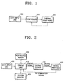
- FIG. 1 is a block diagram of an apparatus for forming an image which does not form part of the invention but is merely an example which is useful for understanding the invention.
- the apparatus comprises a data input unit 300, a controller 310, and a thermal print head 320.
- FIG. 6 is a flowchart illustrating a method of forming an image according to an embodiment of the present invention.
- the controller 310 determines the type of the thermal print head 320 (operation 800).
- the data input unit 300 receives data regarding an image to be printed, from an external device such as a personal computer (PC) or a digital camera (operation 810).
- the controller 310 generates driving signals, such as a clock signal, a latch signal, a data signal, and a strobe signal, to drive the thermal print head 320, based on the type of the thermal print head 320, and inputs the driving signals to the thermal print head 320 (operation 820).
- driving signals such as a clock signal, a latch signal, a data signal, and a strobe signal
- the controller 310 preferably selects an image compensation table that compensates for errors in an image to be printed using the thermal print head 320 according to the type of the thermal print head 320, and outputs values of the compensation table that are preferably included in a driving signal to the thermal print head 320.
- the thermal print head 320 prints the image by heating a medium (not shown) in response to the driving signals (operation 830).
- the thermal print head 320 is preferably rotated to turn toward first and second surfaces of the medium in order to heat both the first and second surfaces.
- FIG. 2 is a block diagram of an image forming apparatus that forms an image by determining the type of a thermal print head 450 and generating driving signals based on the type of the thermal print head 450.
- the print head 450 is removeably received in or mounted to the image forming apparatus, so as to allow the print head 450 to be removed and replaced by a new print head.
- the image forming apparatus comprises a data input unit 400, a driving unit 410, a non-volatile memory 420, a system memory 430, an output buffer 440, and the thermal print head 450.
- the inclusion of the output buffer 440 is optional.
- the non-volatile memory 420 is a memory which retains data even without a supply of power.
- the non-volatile memory 420 may alternatively be a Static Random Access Memory (SRAM) attached with a backup battery, an Erasable and Programmable ROM (EPROM), an Electrically EPROM (EEPROM), a mask ROM, or a flash memory.
- SRAM Static Random Access Memory
- EPROM Erasable and Programmable ROM
- EEPROM Electrically EPROM
- the non-volatile memory 420 preferably stores information regarding the various types of thermal print head that can be installed in the image forming apparatus. The information may specify: (1) the number of data lines; (2) driving signals such as a clock signal, a latch signal, and a strobe signal; (3) bits of data received via a data line; and (4) a thermal print head mapping table that includes an image compensation table.
- the data input unit 400 receives data regarding an image to be printed, from an external device (not shown) such as a PC or a digital camera.
- the driving unit 410 receives a determination signal that has information about the type of thermal print head 450 from the thermal print head 450 via a signal line, and determines the type of the thermal print head 450.
- the determination signal is not sent via a data line through which the driving signals are transmitted to the thermal print head 450 via the output buffer 440.
- the driving unit 410 reads the appropriate information regarding the thermal print head type and the image compensation table from the non-volatile memory 420, generates the driving signals for driving the thermal print head 450 based on the information regarding the thermal print head type, and outputs the driving signals together with the information regarding the image compensation table.
- the output buffer 440 controls the flow of data transmitted from the driving unit 410 to the thermal print head 450, and adjusts the levels of the driving signals generated by the driving unit 410 according to the thermal print head 450.
- the thermal print head 450 prints the image by heating a medium (not shown) in response to the driving signals received from the output buffer 440.
- Figure 3 is a block diagram of an image forming apparatus that forms an image by determining the type of thermal print head 520 and generating driving signals according to the type of the thermal print head 520 according to an embodiment of the present invention.
- the print head 520 is removeably received in or mounted to the image forming apparatus so as to allow the print head 520 to be removed and replaced by another print head.
- the image forming apparatus comprises a data input unit 400, a driving unit 500, a non-volatile memory 420, a system memory 430, an output buffer 510, and the thermal print head 520.
- the data input unit 400 receives data regarding an image to be printed from an external device (not shown). According to a control program stored in the non-volatile memory 420, the driving unit 500 detects a signal output from one of the data lines that connect the output buffer 510 to the thermal print head 520, and determines the type of the thermal print head 520 using the detected signal.
- the driving unit 500 may detect a signal of a data line available to only the A type. Alternatively, the driving unit 500 can determine that the thermal print head 520 is an A type when the data line on which the signal is detected is connected to the thermal print head 520, otherwise, the thermal print head 520 is a B type.
- the driving unit 500 determines whether the type of thermal print head 520 is one of three or more other possible types. For instance, to determine whether the thermal print head 520 is an A, B, or C type, the driving unit 500 detects signals of two data lines, using a combination of the signals of the data lines. If a 10 th data line is available to only the A type and an 11 th data line is available to the C type, the driving unit 500 detects signals of the 10 th and 11 th data lines, but determines that the thermal print head 520 is a C type when the thermal print head 520 is connected only to the 11 th data line.
- the driving unit 500 reads the appropriate information regarding the thermal print head type and an image compensation table from the non-volatile memory 420, generates the driving signals for driving the thermal print head 520 using the information regarding the thermal print head type, and outputs the driving signals together with the information regarding the image compensation table.
- the output buffer 510 adjusts the levels of the driving signals generated by the driving unit 500 and outputs the adjusted driving signals to the thermal print head 520.
- the driving unit 500 preferably controls the operation of the output buffer 510, such that the driving signals are not output to the thermal print head 520 while detecting a signal output from a selected data line and determining the type of the thermal print head 520.
- the driving signals are preferably output to the thermal print head 520 after determining the type of thermal print head 520.
- the thermal print head 520 prints the image by heating a medium (not shown) in response to the driving signals received from the output buffer 510.
- FIG. 4 is a block diagram illustrating a method for detecting a signal output from a data line according to an embodiment of the present invention.
- a signal output from one data line 600 of a plurality data lines which connect an output buffer 510 to a thermal print head 520, is detected by accessing the data line 600.
- the data line 600 is connected to a thermal print head logic power supply voltage V S , for example +5V, through a pull-up resistor R, and the amplitude of the signal output from the data line 600 is measured.
- V S thermal print head logic power supply voltage
- the resistance of the thermal print head 520 is far greater than the resistance of the pull-up resistor R, and thus, when the thermal print head 520 uses the data line 600, the signal output from the data line 600 is at a logic high level.
- the data line 600 is connected to a ground voltage GND, and thus, the signal output from the data line 600 is at a logic low level.
- the driving unit 500 can determine whether the thermal print head 520 uses the data line 600 by checking the logic level of the signal output from the data line 600.
- FIG 5 is a detailed block diagram of the driving unit 500 shown in Figure 4 .
- the driving unit 500 comprises a thermal print head determination unit 700, a signal generator 710, and a buffer controller 720.
- the thermal print head determination unit 700 determines the type of the thermal print head 520 using the signal output from the data line 600.
- the signal generator 710 reads the appropriate information regarding the type of the thermal print head 520 and an image compensation table from the non-volatile memory 420 (as shown in Figure 3 ), and generates and outputs the driving signals, such as a clock signal, a data signal, a latch signal, and a strobe signal, which drive the thermal print head 520 (as shown in Figure 3 ), based on the information regarding the type of thermal print head 520.
- the buffer controller 720 controls the operation of the output buffer 510 (as shown in Figure 3 ), such that the driving signals are not output to the thermal print head 520 when the thermal print head determination unit 700 is determining the type of thermal print head 520, and are output to the thermal print head 520 after the thermal print head determination unit 700 has determined the type of thermal print head 520 and the signal generator 710 generates and outputs the driving signals.
- an image can be printed by determining the type of thermal print head, and generating driving signals for driving the thermal print head according to the type of thermal print head.
- the present invention can be embodied as computer readable code in a computer readable medium.
- the computer readable medium may be any recording apparatus capable of storing data to be read by a computer system, e.g., a read-only memory (ROM), a random access memory (RAM), a compact disc (CD)-ROM, a magnetic tape, a floppy disk, an optical data storage device, and so on.
- the computer readable medium may be a carrier wave that transmits data via the Internet, for example.
- the computer readable recording medium can be distributed among computer systems that are interconnected through a network, and embodiments of the present invention may be stored and implemented as computer readable code in the distributed system.
- a functional program, code, and code segments required to embody the present invention can be derived by programmers in the art.
Landscapes
- Electronic Switches (AREA)
Description
- In recent years, various types of thermal transfer printing apparatus have been developed to print high-resolution images. A thermal transfer printing apparatus forms an image by transferring ink onto a medium by heating an ink ribbon that contacts a medium or by heating an ink layer of a medium to reveal a predetermined colour, using the thermal print head.
- When driving signals, such as a clock signal, a data signal, a latch signal and a strobe signal, are supplied to the thermal print head the thermal print head heats a medium using a plurality of heating units having a predetermined resistance R. The type of thermal print head may differ depending on the manufacturer. For instance, thermal print heads may differ in the number of data lines to which the clock signal and the data signal supplied, the bits of data received via a data line, or the characteristics of the heating units.
-
US-A-2004036724 describe an inkjet printer in which a DC/DC voltage converter converts a voltage, used for supplying power to a printhead, and supplies a converted voltage to the printhead. The converted value is varied according to an information signal from the printhead, such as information indicative of a variation of heater resistances and head temperature. -
US-A-2002012541 describes an image forming apparatus. A detachable process cartridge is provided with identification information in the form of character information, image information such as a bar code, concavo-convex information, magnetic information or electronic information memorized in memory devices. -
US-A 5033887 describes a printer having a circuit for distinguishing between various types of printing head, e.g. between inkjet print head and pin print head. -
EP-A-0780236 describes an inkjet printer having a rank heater representative of the characteristics of the recording head. The recording head is driven according to the resistance value of the rank heater. -
US-A-2003002899 describes an inkjet printer in which information for identifying a printhead is stored in non-volatile memory. - The present invention seeks to provide an improved thermal printer.
- According to the present invention there is provided a thermal printer comprising a driving unit configured to identify a thermal print head, to receive image data and to generate signals for driving the thermal print head in dependence upon an identity of the thermal print head and an output buffer configured to receive said driving signals, to adjust levels of said driving signals and to output adjusted signals to the thermal print head via a plurality of data line, wherein the driving unit is configured to select a predetermined one of the plurality of data lines and to determine a signal in the predetermined one of data lines so as to identify the thermal print head and is further configured to control the output buffer such that the adjusted driving signals are not output to the thermal print head while determining the signal.
- The thermal print head may be rotatable so as to turn towards fist and second surfaces of a print medium.
- The thermal printer may further comprise a memory which stores information regarding various types of thermal print heads and the driving unit may be configured to read information regarding the thermal print head type from the memory and to generate the driving signals based on the read information.
- The information regarding the thermal print head type may specify at least one of the number of data lines of the thermal print head, the number of bits of data received via the data lines, a clock signal, a strobe signal, and an image compensation table.
- The driving unit may comprise a thermal print head determination unit configured to detect the signal of the predetermined one of a plurality of data lines connected to the thermal print head and to determine the thermal print head type, a signal generator configured to read the information regarding the thermal print head type from the memory and to generate the driving signals and a buffer controller which controls operation of the output buffer, such that the driving signals are not output to the thermal print head when the thermal print head determination unit is determining the thermal print head type, and are output to the thermal print head after the signal generator generates the driving signals.
- The predetermined data line may not be available to at least one of the various types of thermal print heads.
- The thermal print head determination unit may be configured to determine a signal of a predetermined one of the plurality of data lines connected to the thermal print head by pulling up the predetermined data line and, using the detected signal, determining the thermal print head type by checking whether the thermal print head uses the predetermined data line.
- According to the present invention there is also provided a method of operating a thermal printer, the method comprising identifying a thermal print head, receiving image data, generating signals for driving the thermal print head in dependence upon an identity of the thermal print head, adjusting levels of said driving signals and outputting adjusted signals to the thermal print head via a plurality of data lines, wherein identifying the thermal print head comprises selecting a predetermined one of the plurality of data lines and determining a signal in the predetermined one of data lines so as to identify the thermal print head and the method comprises controlling output of the adjusted driving signals such they are not output to the thermal print head while determining the signal.
- The method may further comprise rotating the thermal print head between positions turned towards a first surface and a second surface of the medium.
- The predetermined data line may not be available to at least one of a plurality of thermal print heads whose types are to be determined.
- Generating the driving signals may comprise reading information regarding the thermal print head type from a memory which stores information regarding various types of thermal print heads and generating the driving signals for driving the thermal print head based on the information regarding the thermal print head type.
- The information regarding the thermal print head type may specify at least one of the number of data lines of the thermal print head, the number of bits of data received via a data line, a clock signal, a strobe signal, and an image compensation table.
- According to the present invention there is still further provided a computer program which, when executed by a thermal printer, causes the thermal printer to perform the method.
- According to the present invention there is yet still further provided a computer readable medium storing the computer program.
- Embodiments of the present invention will now be described, by way of example, with reference to the accompanying drawings in which:
-
Figure 1 is a block diagram of an image forming apparatus; -
Figure 2 is a block diagram of an image forming apparatus that determines a thermal print head type and prints an image by generating driving signals based on the type of thermal print head; -
Figure 3 is a block diagram of an image forming apparatus that determines a thermal print head type and prints an image by generating driving signals based on the type of thermal print head according to an embodiment of the present invention; -
Figure 4 is a block diagram illustrating a method of detecting a signal output from a data line according to an embodiment of the present invention; -
Figure 5 is a block diagram of a driving unit shown inFigure 4 ; and -
Figure 6 is a flowchart illustrating a method of forming an image by determining a thermal print head type and generating driving signals for driving the thermal print head according to the thermal print head type, according to an embodiment of the present invention. -
Figure 1 is a block diagram of an apparatus for forming an image which does not form part of the invention but is merely an example which is useful for understanding the invention. Referring toFigure 1 , the apparatus comprises adata input unit 300, acontroller 310, and athermal print head 320. - Operation of the apparatus will now be described with reference to
Figures 1 and6. Figure 6 is a flowchart illustrating a method of forming an image according to an embodiment of the present invention. Referring toFigure 6 , thecontroller 310 determines the type of the thermal print head 320 (operation 800). Next, thedata input unit 300 receives data regarding an image to be printed, from an external device such as a personal computer (PC) or a digital camera (operation 810). Next, thecontroller 310 generates driving signals, such as a clock signal, a latch signal, a data signal, and a strobe signal, to drive thethermal print head 320, based on the type of thethermal print head 320, and inputs the driving signals to the thermal print head 320 (operation 820). Inoperation 820, thecontroller 310 preferably selects an image compensation table that compensates for errors in an image to be printed using thethermal print head 320 according to the type of thethermal print head 320, and outputs values of the compensation table that are preferably included in a driving signal to thethermal print head 320. - Next, the
thermal print head 320 prints the image by heating a medium (not shown) in response to the driving signals (operation 830). Thethermal print head 320 is preferably rotated to turn toward first and second surfaces of the medium in order to heat both the first and second surfaces. -
Figure 2 is a block diagram of an image forming apparatus that forms an image by determining the type of athermal print head 450 and generating driving signals based on the type of thethermal print head 450. Theprint head 450 is removeably received in or mounted to the image forming apparatus, so as to allow theprint head 450 to be removed and replaced by a new print head. The image forming apparatus comprises adata input unit 400, adriving unit 410, anon-volatile memory 420, asystem memory 430, anoutput buffer 440, and thethermal print head 450. In this embodiment, the inclusion of theoutput buffer 440 is optional. - The
non-volatile memory 420 is a memory which retains data even without a supply of power. Thenon-volatile memory 420 may alternatively be a Static Random Access Memory (SRAM) attached with a backup battery, an Erasable and Programmable ROM (EPROM), an Electrically EPROM (EEPROM), a mask ROM, or a flash memory. Thenon-volatile memory 420 preferably stores information regarding the various types of thermal print head that can be installed in the image forming apparatus. The information may specify: (1) the number of data lines; (2) driving signals such as a clock signal, a latch signal, and a strobe signal; (3) bits of data received via a data line; and (4) a thermal print head mapping table that includes an image compensation table. - The
data input unit 400 receives data regarding an image to be printed, from an external device (not shown) such as a PC or a digital camera. According to a control program stored in thenon-volatile memory 420, thedriving unit 410 receives a determination signal that has information about the type ofthermal print head 450 from thethermal print head 450 via a signal line, and determines the type of thethermal print head 450. The determination signal is not sent via a data line through which the driving signals are transmitted to thethermal print head 450 via theoutput buffer 440. - The
driving unit 410 reads the appropriate information regarding the thermal print head type and the image compensation table from thenon-volatile memory 420, generates the driving signals for driving thethermal print head 450 based on the information regarding the thermal print head type, and outputs the driving signals together with the information regarding the image compensation table. - The
output buffer 440 controls the flow of data transmitted from thedriving unit 410 to thethermal print head 450, and adjusts the levels of the driving signals generated by thedriving unit 410 according to thethermal print head 450. Thethermal print head 450 prints the image by heating a medium (not shown) in response to the driving signals received from theoutput buffer 440. -
Figure 3 is a block diagram of an image forming apparatus that forms an image by determining the type ofthermal print head 520 and generating driving signals according to the type of thethermal print head 520 according to an embodiment of the present invention. Theprint head 520 is removeably received in or mounted to the image forming apparatus so as to allow theprint head 520 to be removed and replaced by another print head. The image forming apparatus comprises adata input unit 400, adriving unit 500, anon-volatile memory 420, asystem memory 430, anoutput buffer 510, and thethermal print head 520. - The
data input unit 400 receives data regarding an image to be printed from an external device (not shown). According to a control program stored in thenon-volatile memory 420, thedriving unit 500 detects a signal output from one of the data lines that connect theoutput buffer 510 to thethermal print head 520, and determines the type of thethermal print head 520 using the detected signal. - To determine whether the
thermal print head 520 is an A type or a B type, thedriving unit 500 may detect a signal of a data line available to only the A type. Alternatively, the drivingunit 500 can determine that thethermal print head 520 is an A type when the data line on which the signal is detected is connected to thethermal print head 520, otherwise, thethermal print head 520 is a B type. - Also, it is possible to determine whether the type of
thermal print head 520 is one of three or more other possible types. For instance, to determine whether thethermal print head 520 is an A, B, or C type, the drivingunit 500 detects signals of two data lines, using a combination of the signals of the data lines. If a 10th data line is available to only the A type and an 11th data line is available to the C type, the drivingunit 500 detects signals of the 10th and 11th data lines, but determines that thethermal print head 520 is a C type when thethermal print head 520 is connected only to the 11th data line. - The driving
unit 500 reads the appropriate information regarding the thermal print head type and an image compensation table from thenon-volatile memory 420, generates the driving signals for driving thethermal print head 520 using the information regarding the thermal print head type, and outputs the driving signals together with the information regarding the image compensation table. - Under the control of the
driving unit 500, theoutput buffer 510 adjusts the levels of the driving signals generated by the drivingunit 500 and outputs the adjusted driving signals to thethermal print head 520. The drivingunit 500 preferably controls the operation of theoutput buffer 510, such that the driving signals are not output to thethermal print head 520 while detecting a signal output from a selected data line and determining the type of thethermal print head 520. The driving signals are preferably output to thethermal print head 520 after determining the type ofthermal print head 520. - The
thermal print head 520 prints the image by heating a medium (not shown) in response to the driving signals received from theoutput buffer 510. -
Figure 4 is a block diagram illustrating a method for detecting a signal output from a data line according to an embodiment of the present invention. Referring toFigure 4 , a signal output from onedata line 600 of a plurality data lines, which connect anoutput buffer 510 to athermal print head 520, is detected by accessing thedata line 600. Specifically, thedata line 600 is connected to a thermal print head logic power supply voltage VS, for example +5V, through a pull-up resistor R, and the amplitude of the signal output from thedata line 600 is measured. The resistance of thethermal print head 520 is far greater than the resistance of the pull-up resistor R, and thus, when thethermal print head 520 uses thedata line 600, the signal output from thedata line 600 is at a logic high level. When thethermal print head 520 does not use thedata line 600, thedata line 600 is connected to a ground voltage GND, and thus, the signal output from thedata line 600 is at a logic low level. - Thus, the driving
unit 500 can determine whether thethermal print head 520 uses thedata line 600 by checking the logic level of the signal output from thedata line 600. -
Figure 5 is a detailed block diagram of thedriving unit 500 shown inFigure 4 . The drivingunit 500 comprises a thermal printhead determination unit 700, asignal generator 710, and abuffer controller 720. - The thermal print
head determination unit 700 determines the type of thethermal print head 520 using the signal output from thedata line 600. Thesignal generator 710 reads the appropriate information regarding the type of thethermal print head 520 and an image compensation table from the non-volatile memory 420 (as shown inFigure 3 ), and generates and outputs the driving signals, such as a clock signal, a data signal, a latch signal, and a strobe signal, which drive the thermal print head 520 (as shown inFigure 3 ), based on the information regarding the type ofthermal print head 520. - The
buffer controller 720 controls the operation of the output buffer 510 (as shown inFigure 3 ), such that the driving signals are not output to thethermal print head 520 when the thermal printhead determination unit 700 is determining the type ofthermal print head 520, and are output to thethermal print head 520 after the thermal printhead determination unit 700 has determined the type ofthermal print head 520 and thesignal generator 710 generates and outputs the driving signals. - As described above, according to embodiments of the present invention, an image can be printed by determining the type of thermal print head, and generating driving signals for driving the thermal print head according to the type of thermal print head. Thus, it is possible to reduce or eliminate the inconvenience caused by requiring a user to check the type of a new thermal print head and to set the thermal print head type whenever a thermal print head is exchanged. Furthermore, errors due to the user incorrectly setting the type of thermal print head can be prevented.
- The present invention can be embodied as computer readable code in a computer readable medium. Here, the computer readable medium may be any recording apparatus capable of storing data to be read by a computer system, e.g., a read-only memory (ROM), a random access memory (RAM), a compact disc (CD)-ROM, a magnetic tape, a floppy disk, an optical data storage device, and so on. Also, the computer readable medium may be a carrier wave that transmits data via the Internet, for example. The computer readable recording medium can be distributed among computer systems that are interconnected through a network, and embodiments of the present invention may be stored and implemented as computer readable code in the distributed system. A functional program, code, and code segments required to embody the present invention can be derived by programmers in the art.
- While this invention has been particularly shown and described with reference to exemplary embodiment thereof, it will be understood by those skilled in the art that various changes in form and details may be made therein without departing from the scope of the invention as defined by the appended claims.
Claims (14)
- A thermal printer comprising:a driving unit (500) configured to identify a thermal print head, to receive image data and to generate signals for driving the thermal print head in dependence upon an identity of the thermal print head; andan output buffer (510) configured to receive said driving signals, to adjust levels of said driving signals and to output adjusted signals to the thermal print head via a plurality of data lines (600);wherein the driving unit is configured to select a predetermined one of the plurality of data lines and to determine a signal in the predetermined one of data lines so as to identify the thermal print head and is further configured to control the output buffer such that the adjusted driving signals are not output to the thermal print head while determining the signal.
- A thermal printer according to claim 1, wherein the thermal print head is rotatable so as to turn towards fist and second surfaces of a print medium.
- A thermal printer according to claim 1 or 2, further comprising:a memory (420) which stores information regarding various types of thermal print heads;wherein the driving unit (500) is configured to read information regarding the thermal print head type from the memory and to generate the driving signals based on the read information.
- A thermal printer according to claim 3, wherein the information regarding the thermal print head type specifies at least one of the number of data lines of the thermal print head, the number of bits of data received via the data lines, a clock signal, a strobe signal, and an image compensation table.
- A thermal printer according to claim 4, wherein the driving unit (500) comprises:a thermal print head determination unit (700) configured to detect the signal of the predetermined one of a plurality of data lines connected to the thermal print head and to determine the thermal print head type;a signal generator (710) configured to read the information regarding the thermal print head type from the memory and to generate the driving signals; anda buffer controller (720) which controls operation of the output buffer (510), such that the driving signals are not output to the thermal print head when the thermal print head determination unit is determining the thermal print head type, and are output to the thermal print head after the signal generator generates the driving signals.
- A thermal printer according to claim 5, wherein the predetermined data line is not available to at least one of the various types of thermal print heads.
- A thermal printer according to claim 5 or 6, wherein the thermal print head determination unit is configured to determine a signal of a predetermined one of the plurality of data lines connected to the thermal print head by pulling up the predetermined data line and, using the detected signal, determining the thermal print head type by checking whether the thermal print head uses the predetermined data line.
- A method of operating a thermal printer, the method comprising:identifying a thermal print head;receiving image data;generating signals for driving the thermal print head in dependence upon an identity of the thermal print head; andadjusting levels of said driving signals; andoutputting adjusted signals to the thermal print head via a plurality of data lines (600);wherein identifying the thermal print head comprises:selecting a predetermined one of the plurality of data lines; anddetermining a signal in the predetermined one of data lines so as to identify the thermal print head; and the method further comprises:controlling output of the adjusted driving signals such they are not output to the thermal print head while determining the signal.
- A method according to claim 8, further comprising:rotating the thermal print head between positions turned towards a first surface and a second surface of the medium.
- A method according to claim 8 to 9, wherein the predetermined data line is not available to at least one of a plurality of thermal print heads whose types are to be determined.
- A method according to any one of claims 8 to 10, wherein generating the driving signals comprises:reading information regarding the thermal print head type from a memory which stores information regarding various types of thermal print heads; andgenerating the driving signals for driving the thermal print head based on the information regarding the thermal print head type.
- A method according to claim 11, wherein the information regarding the thermal print head type specifies at least one of the number of data lines of the thermal print head, the number of bits of data received via a data line, a clock signal, a strobe signal, and an image compensation table.
- A computer program comprising code means adapted to perform the method according to any one of claims 8 to 12, when executed by a computer of a thermal printer.
- A computer readable medium storing a computer program according to claim 13.
Applications Claiming Priority (1)
| Application Number | Priority Date | Filing Date | Title |
|---|---|---|---|
| KR1020040090352A KR100636190B1 (en) | 2004-11-08 | 2004-11-08 | An image forming apparatus and method for automatically recognizing the type of thermal transfer head and printing an image |
Publications (2)
| Publication Number | Publication Date |
|---|---|
| EP1661711A1 EP1661711A1 (en) | 2006-05-31 |
| EP1661711B1 true EP1661711B1 (en) | 2008-12-03 |
Family
ID=36087348
Family Applications (1)
| Application Number | Title | Priority Date | Filing Date |
|---|---|---|---|
| EP05110200A Expired - Lifetime EP1661711B1 (en) | 2004-11-08 | 2005-10-31 | Image forming apparatus |
Country Status (5)
| Country | Link |
|---|---|
| US (1) | US7649542B2 (en) |
| EP (1) | EP1661711B1 (en) |
| KR (1) | KR100636190B1 (en) |
| CN (1) | CN100471679C (en) |
| DE (1) | DE602005011387D1 (en) |
Families Citing this family (8)
| Publication number | Priority date | Publication date | Assignee | Title |
|---|---|---|---|---|
| US8721203B2 (en) * | 2005-10-06 | 2014-05-13 | Zih Corp. | Memory system and method for consumables of a printer |
| EP2133209A3 (en) * | 2008-06-12 | 2010-02-24 | Toshiba TEC Kabushiki Kaisha | Printing apparatus |
| EP3121013B1 (en) | 2012-01-05 | 2019-09-04 | Zebra Technologies Corporation | Method and apparatus for printhead control |
| EP2817723B1 (en) | 2012-02-21 | 2017-06-07 | ZIH Corp. | Electrically configurable option board interface |
| US9561646B2 (en) | 2015-03-27 | 2017-02-07 | Zih Corp. | High speed adaptive thermal printhead interface |
| CN109278420A (en) * | 2017-07-20 | 2019-01-29 | 精工爱普生株式会社 | Printing unit and thermal head |
| KR102102631B1 (en) * | 2019-06-17 | 2020-04-22 | 주식회사 빅솔론 | Thermal print head, thermal printer, method of controlling thermal printer and computer readable medium |
| CN121716432B (en) * | 2026-02-25 | 2026-05-12 | 珠海芯烨电子科技有限公司 | Printing quality compensation method of dual-mode printer and dual-mode printer |
Family Cites Families (17)
| Publication number | Priority date | Publication date | Assignee | Title |
|---|---|---|---|---|
| JPS56167484A (en) | 1980-05-30 | 1981-12-23 | Canon Inc | Printer |
| JPS5857977A (en) * | 1981-10-02 | 1983-04-06 | Canon Inc | Thermal transcription printer |
| JPH01249366A (en) * | 1988-03-31 | 1989-10-04 | Canon Inc | thermal recording device |
| US5033887A (en) * | 1988-07-25 | 1991-07-23 | Nixdorf Computer Ag | Process for the production of information relative to the type of a printing head |
| JPH0462073A (en) | 1990-06-25 | 1992-02-27 | Seikosha Co Ltd | Printer |
| JPH05278300A (en) | 1991-11-06 | 1993-10-26 | Nec Eng Ltd | Printer exchanging head of different kind |
| JPH07237306A (en) * | 1994-02-28 | 1995-09-12 | Fujitsu Ltd | Identification device of print head in printer |
| US5940095A (en) | 1995-09-27 | 1999-08-17 | Lexmark International, Inc. | Ink jet print head identification circuit with serial out, dynamic shift registers |
| JPH09169114A (en) | 1995-12-20 | 1997-06-30 | Canon Inc | Ink jet recording device |
| JP3531380B2 (en) * | 1996-09-19 | 2004-05-31 | ブラザー工業株式会社 | Inspection method of print head unit and its inspection device |
| JPH10100395A (en) | 1996-09-26 | 1998-04-21 | Canon Inc | Inkjet printer |
| JPH11192703A (en) | 1997-12-29 | 1999-07-21 | Canon Inc | Printers and printer heads |
| US7101099B1 (en) | 1998-08-19 | 2006-09-05 | Canon Kabushiki Kaisha | Printing head, head cartridge having printing head, printing apparatus using printing head, and printing head substrate |
| JP2001310503A (en) * | 2000-04-28 | 2001-11-06 | Canon Inc | Recording device |
| JP2002006702A (en) * | 2000-06-26 | 2002-01-11 | Konica Corp | Image forming apparatus, method of controlling image forming apparatus, method of managing image forming apparatus |
| JP3793017B2 (en) * | 2000-11-07 | 2006-07-05 | セイコーインスツル株式会社 | Thermal head discrimination device and discrimination method |
| JP3880411B2 (en) | 2001-01-31 | 2007-02-14 | キヤノン株式会社 | Recording device |
-
2004
- 2004-11-08 KR KR1020040090352A patent/KR100636190B1/en not_active Expired - Fee Related
-
2005
- 2005-07-26 US US11/188,982 patent/US7649542B2/en not_active Expired - Fee Related
- 2005-10-31 CN CNB2005101187478A patent/CN100471679C/en not_active Expired - Fee Related
- 2005-10-31 EP EP05110200A patent/EP1661711B1/en not_active Expired - Lifetime
- 2005-10-31 DE DE602005011387T patent/DE602005011387D1/en not_active Expired - Lifetime
Also Published As
| Publication number | Publication date |
|---|---|
| US7649542B2 (en) | 2010-01-19 |
| KR100636190B1 (en) | 2006-10-19 |
| CN1772491A (en) | 2006-05-17 |
| DE602005011387D1 (en) | 2009-01-15 |
| US20060098078A1 (en) | 2006-05-11 |
| KR20060041005A (en) | 2006-05-11 |
| EP1661711A1 (en) | 2006-05-31 |
| CN100471679C (en) | 2009-03-25 |
Similar Documents
| Publication | Publication Date | Title |
|---|---|---|
| KR100475847B1 (en) | Access to printing material container | |
| US5835817A (en) | Replaceable part with integral memory for usage, calibration and other data | |
| US8721203B2 (en) | Memory system and method for consumables of a printer | |
| EP1594702B1 (en) | Printer consumable having data storage for static and dynamic calibration data | |
| US5691750A (en) | Ink level sensing for disposable ink jet print head cartridges | |
| KR950026684A (en) | Printing head, printing method and apparatus using the same, and apparatus and method for calibrating the printing head | |
| US7649542B2 (en) | Apparatus and method for forming image by detecting thermal print head type | |
| US20110221819A1 (en) | Printing apparatus, method of correcting in printing apparatus, and storage medium storing program thereof | |
| US7245389B2 (en) | Burst mode for printing devices | |
| JP4596757B2 (en) | Recording head test equipment | |
| JP2008529863A (en) | Systems and methods for using donor materials | |
| JP3793017B2 (en) | Thermal head discrimination device and discrimination method | |
| US6325481B1 (en) | Method and apparatus for pen temperature control in a thermal printer | |
| KR20070095505A (en) | Image Forming System, Host Device, Image Forming Device and Image Forming Method Using The Same | |
| KR100492115B1 (en) | Head Temperature Control Apparatus And Method thereof | |
| JP4075943B2 (en) | Printer, printer system, and error detection method in printer | |
| KR20070054172A (en) | Image Forming System, Host Device, Image Forming Device and Image Forming Method Using The Same | |
| JP4193002B2 (en) | Printer and error check method in printer | |
| KR100412768B1 (en) | Thermal Printer | |
| JPS6325081A (en) | Recording device | |
| JPH01165458A (en) | Print density correction device of thermal printer | |
| JPH10324013A (en) | Thermal transfer printer | |
| JPH0946486A (en) | Image processing apparatus and control method thereof | |
| JPH07148954A (en) | Thermal transfer recorder | |
| JP2001225529A (en) | Printing system and printer |
Legal Events
| Date | Code | Title | Description |
|---|---|---|---|
| PUAI | Public reference made under article 153(3) epc to a published international application that has entered the european phase |
Free format text: ORIGINAL CODE: 0009012 |
|
| AK | Designated contracting states |
Kind code of ref document: A1 Designated state(s): AT BE BG CH CY CZ DE DK EE ES FI FR GB GR HU IE IS IT LI LT LU LV MC NL PL PT RO SE SI SK TR |
|
| AX | Request for extension of the european patent |
Extension state: AL BA HR MK YU |
|
| 17P | Request for examination filed |
Effective date: 20061130 |
|
| AKX | Designation fees paid |
Designated state(s): DE FR GB NL |
|
| 17Q | First examination report despatched |
Effective date: 20070112 |
|
| GRAP | Despatch of communication of intention to grant a patent |
Free format text: ORIGINAL CODE: EPIDOSNIGR1 |
|
| GRAS | Grant fee paid |
Free format text: ORIGINAL CODE: EPIDOSNIGR3 |
|
| GRAA | (expected) grant |
Free format text: ORIGINAL CODE: 0009210 |
|
| AK | Designated contracting states |
Kind code of ref document: B1 Designated state(s): DE FR GB NL |
|
| REG | Reference to a national code |
Ref country code: GB Ref legal event code: FG4D |
|
| REF | Corresponds to: |
Ref document number: 602005011387 Country of ref document: DE Date of ref document: 20090115 Kind code of ref document: P |
|
| PLBE | No opposition filed within time limit |
Free format text: ORIGINAL CODE: 0009261 |
|
| STAA | Information on the status of an ep patent application or granted ep patent |
Free format text: STATUS: NO OPPOSITION FILED WITHIN TIME LIMIT |
|
| 26N | No opposition filed |
Effective date: 20090904 |
|
| PGFP | Annual fee paid to national office [announced via postgrant information from national office to epo] |
Ref country code: GB Payment date: 20131011 Year of fee payment: 9 Ref country code: FR Payment date: 20131015 Year of fee payment: 9 Ref country code: DE Payment date: 20131015 Year of fee payment: 9 |
|
| PGFP | Annual fee paid to national office [announced via postgrant information from national office to epo] |
Ref country code: NL Payment date: 20131014 Year of fee payment: 9 |
|
| REG | Reference to a national code |
Ref country code: DE Ref legal event code: R119 Ref document number: 602005011387 Country of ref document: DE |
|
| REG | Reference to a national code |
Ref country code: NL Ref legal event code: V1 Effective date: 20150501 |
|
| GBPC | Gb: european patent ceased through non-payment of renewal fee |
Effective date: 20141031 |
|
| PG25 | Lapsed in a contracting state [announced via postgrant information from national office to epo] |
Ref country code: GB Free format text: LAPSE BECAUSE OF NON-PAYMENT OF DUE FEES Effective date: 20141031 Ref country code: DE Free format text: LAPSE BECAUSE OF NON-PAYMENT OF DUE FEES Effective date: 20150501 |
|
| REG | Reference to a national code |
Ref country code: FR Ref legal event code: ST Effective date: 20150630 |
|
| PG25 | Lapsed in a contracting state [announced via postgrant information from national office to epo] |
Ref country code: NL Free format text: LAPSE BECAUSE OF NON-PAYMENT OF DUE FEES Effective date: 20150501 Ref country code: FR Free format text: LAPSE BECAUSE OF NON-PAYMENT OF DUE FEES Effective date: 20141031 |
|
| REG | Reference to a national code |
Ref country code: GB Ref legal event code: 732E Free format text: REGISTERED BETWEEN 20170406 AND 20170412 |
|
| REG | Reference to a national code |
Ref country code: FR Ref legal event code: TP Owner name: S-PRINTING SOLUTION CO., LTD., KR Effective date: 20170912 |